

Page 1
AP-303H-MNTW Wall Mount Kit
Installation Guide
Package Contents
AP-303H-MNTW plastic mount bracket
(2) Blank Keystone jack cover
(2) #6-32 x 1.5” slotted screws
M2.5 x 0.45P x 6.5 security screw
AP-303H-MNTW Wall Mount Kit Installation Guide
Introduction
The AP-303H-MNTW wall mount kit provides the materials required to mount a 303H access point to
a flat surface or single gang wall box.
Refer to the following section for complete installation instructions.
Installing the AP-303H-MNTW
This section contains instructions for installing the AP-303H-MNTW wall mount kit.
To install the mount bracket onto a flat surface, see Installing the AP-303H-MNTW to a flat surface. To
install the mount bracket onto a singlel gang wall box, see Installing the AP-303H-MNTW to a wall box.
Installing the AP-303H-MNTW to a flat surface
Before installing the AP-303H-MNTW Wall Mount Kit to any surface, ensure that the mounting surface can support
the combined weight of the mount kit and access point.
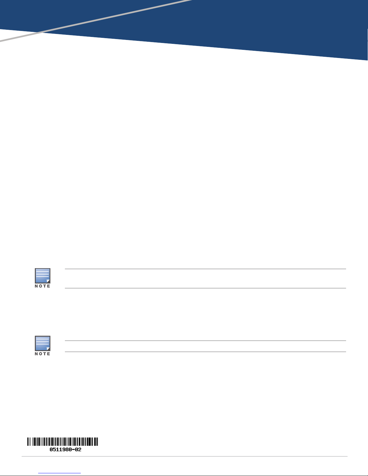
1. Choose the desired location to mount the AP-303H-MNTW, then mark and drill pilot holes into the
mounting surface.
2. Position the mounting bracket flat against the surface so that the pilot holes align with
corresponding screw holes , then screw the bracket into place, as shown in Figure 1.
Screws for Step 2 are not provided in this kit. The screw used for this step will vary depending on the surface.
3. Use the RJ45 jumper cable provided to link the E0 and PT ports located on the back of the access
point.
0511980-02 | April 2017 1
Page 2
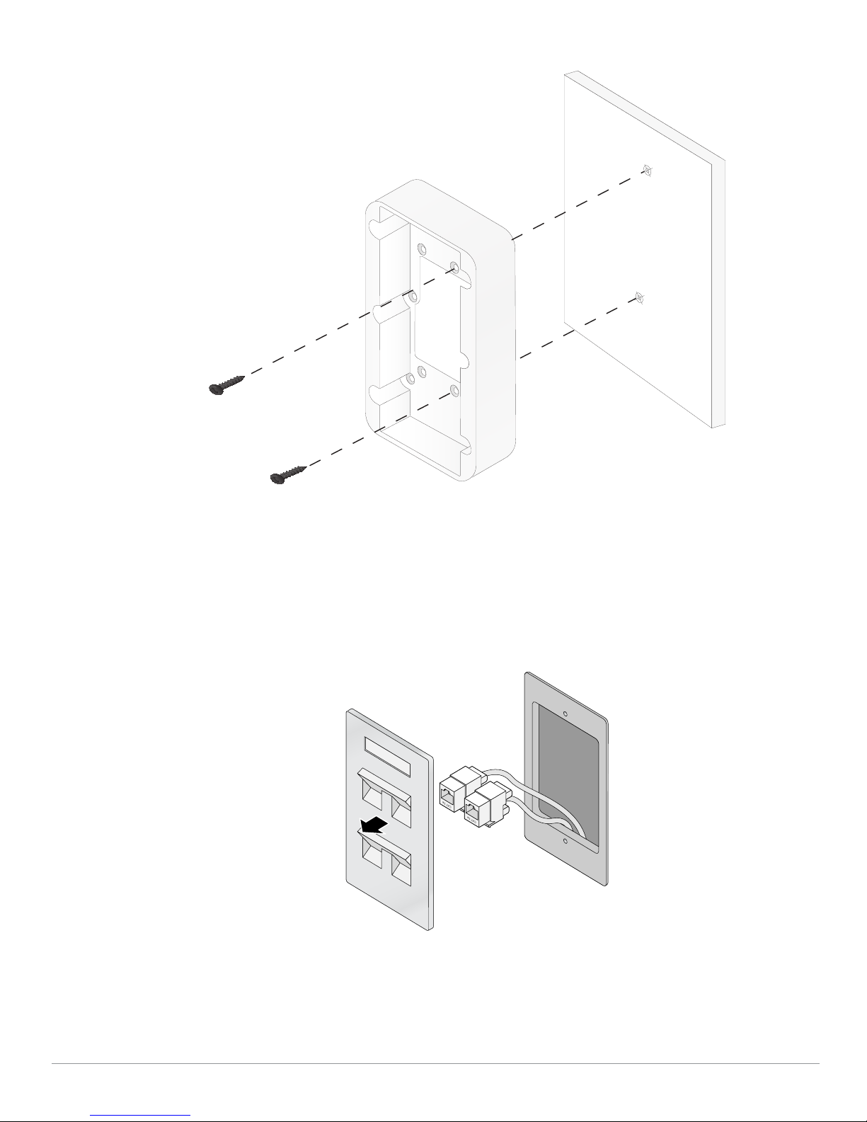
Figure 1 Attaching the AP-303H-MNTW to a flat surface
Installing the AP-303H-MNTW to a wall box
1. If the wall box is not already exposed, unscrew and remove the existing wall plate, as shown in
e 2. Detach any RJ45 cables by unclipping the connectors from the wall plate, or cutting/
Figur
removing the UTP cable(s).
Figure 2 Removing an existing wall plate
2. Use an Ethernet cable, to link the E0 port to an active RJ45 connector, or crimp an RJ45 plug to the
cable, and insert
Align the wall mount with the holes on your single gang wall box, then use the #6-32 x 1.5” screws
3.
to secure the plastic bracket to the wall box.
it into the E0 port.
2 AP-303H-MNTW Wall Mount Kit | Installation Guide
Page 3

The wall mount contains two sets of holes to accommodate standard worldwide (Figure 3) and US
(Figure 4) single gang wall boxes.
The applicable standards for the wall boxes are:
Worldwide: IEC 60670-1, GB17466, BS4662, and DIN49073
US: ANSI/NEMA OS 1 and OS 2
ure 3 Attaching the wall mount to the wall box (worldwide single gang outlet box)
Fig
Figure 4 Attaching the wall mount to the wall box (US single gang outlet box)
AP-303H-MNTW Wall Mount Kit | Installation Guide 3
Page 4

4. If available, route an Ethernet cable from the wall and connect to the PT port located on the back
UP
access point
of the
Mounting the access point
5. (Optional) If there are any additional wires that are left unused for this installation, remove the
blank Keystone jack cover(s) from the AP-303H-MNTW by squeezing the tabs on
disengage the clips
nsert a Keystone module that corresponds with the unused cable, Once the Keystone module
I
ped into the AP-303H-MNTW, connect the cable to the wall-facing side of the jack.
clip
If the unused cable(s) does/do not have a corresponding Keystone module, the installer ca
remove
outward. Once removed, additional cables may be routed through the top of the AP-303H-MNTW
for contin
Figure 5 Removing Keystone jack covers and
the panel located at the top of the plastic bracket by squeezing the clips and pullin
ued use.
and pull outward to remove the tab(s), as shown in Figure 5
either side to
.
is
n
g
6. Align the mounting slots on the back of the 303H access point access poin
sts on the AP-303H-MNTW wall mount, as shown in Figure 6. Press the access
po
mounting bracket
and pull downward to engage the pins with slots.
t with the corresponding
point into the
4 AP-303H-MNTW Wall Mount Kit | Installation Guide
Page 5

Figure 6 Mounting the 303H access point Access Point
UP
57V 600mA
E0
7. Once the access point is attached to the wall mount, insert the security screw into the hole locate
on
the right side of the mount and tighten.
8. Connect Ethernet cable(s) to the bottom of the access point as needed.
d
© Copyright 2017 Hewlett Packard Enterprise Development LP
AP-303H-MNTW Wall Mount Kit | Installation Guide 5
 Loading...