

Page 1

Quick Start Guide
AP2750 Managed Access Point
3CRWX275075A
The 3Com AP2750 Managed Access Point provides IEEE 802.11a or 802.11b/g wireless access to the
network. The access point is designed for use with a 3Com Wireless LAN Switch, and requires
hardware installation only. All configuration for the access point takes place on the 3Com Wireless
LAN Switch.
You must have a wireless switch device to operate the access point. Two WLAN switch devices can be
connected to the access point:
• 3Com WX4400
• 3Com WX1200
Power can be supplied via Power Over Ethernet (PoE) or by an external power supply. Four 3Com PoE
devices supply power to the access point:
• 3Com PoE Injector
• 3Com 4400PWR PoE Switch
• 3Com Multi-port PoE power supply
• 3Com WX1200
About This Guide
This Quick Start Guide describes the basic installation of the access point. It covers the following topics:
• 3Com AP2750 Managed Access Point Features
• Observing Safety Precautions
•Step 1: Unpacking the Access Point
•Step 2: Preparing for Installation
•Step 3: Attaching the Antennas
•Step 4: Mounting the Access Point
•Step 5: Connecting the Access Point to a Switch
•Step 6: Checking the LED Indicators
• Troubleshooting
Page 2
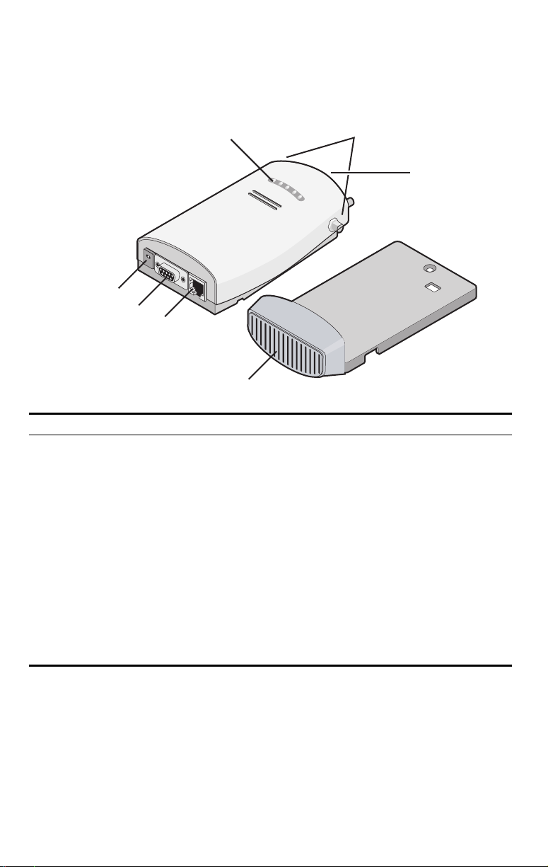
3Com AP2750 Managed Access Point Features
LEDs
Antenna
Connectors
Reset
Button
Power Port
Serial Port
Ethernet Port
Mounting
Bracket
Feature Description
Power Port The access point can be powered either via Power Over Ethernet (PoE), or by an
Serial Port The serial port is not supported.
Ethernet Port The Ethernet port provides a 10/100BASE-TX Ethernet connection to a 3Com Wireless
LEDs The LEDs indicate power and activity. See “Checking the LED Indicators” on page 7
Antenna Connectors Two SMA-female antenna connectors allow you to connect antennas that operate in
Reset Button The reset button is accessible from the back of the access point as well as through the
Mounting Bracket The mounting bracket comes attached to the access point. This mounting bracket
external power supply (not included) that is plugged into the Power
LAN switch. The connection can be direct to a 3Com switch or indirect through an
intermediate Layer 2 or Layer 3 network.
Use a standard Category 5 cable with straight-through signaling and standard RJ-45
connectors to connect the access point to the switch on the network.
for details.
2.4 GHz and 5.3 GHz bands.
mounting bracket. Push the reset button to restore the access point to its factory
default settings.
allows the access point to be mounted to a wall or ceiling.
Port.
Page 3
Observing Safety Precautions
This equipment must be installed in compliance with local and national building codes, regulatory
restrictions, and FCC rules. For the safety of people and equipment, only professional network personnel
should install the access point.
WARNING: To comply with FCC radio frequency (RF) exposure limits, a minimum body-to-
antenna distance of 20 cm (8 in.) must be maintained when the access point is operational.
WARNING: To avoid possible injury or damage to equipment, you must use power supply equipment
that is safety certified according to UL, CSA, IEC, or other applicable national or international safety
requirements for the country of use. All references to power supply in this document refer to equipment
meeting these requirements.
1 Unpacking the Access Point
Make sure that you have the following items, which are included with the access point:
• Two external 2.4 GHz and 5.3 GHz dual-band antennas
• Mounting bracket (attached to the access point)
• Wall-mounting hardware:
• Locking bar (used for securing a wall- or ceiling-mounted installation)
• Two sheet metal screws
• Two thread screws
• Two wall anchors
• Four adhesive rubber feet (used for a flat-surface installation).
2 Preparing for Installation
It is advisable to connect the power (if using an external power supply) and check the Ethernet cables
and LEDs before installing the access
point in a hard-to-reach location. Additionally, observe the
following items before mounting or connecting the access point:
Installation Item Description
Switch port 3Com recommends that you install and configure the 3Com Wireless LAN switch
Cabling Make sure that standard Category 5 cable with straight-through signaling is
Power Requirements Power can be supplied via an 802.3af Power Over Ethernet (PoE)-compliant device
MAC Address Record the access point MAC address in a safe place before the access point is
before installing the access point. Set the port type on the switch to an AP2750
access point.
installed at the site before you install the access point.
Make sure that the cable is highly flexible and that there is no extra covering on the
RJ-45 connector that could prevent the cable from being routed through the
mounting bracket.
or by an external power supply with a minimum 5v @ 2.0 amp.
If using an external power supply, make sure the power outlet is accessible. The
power supply plug is the only means of disconnecting the access point from power.
installed in a hard-to-reach location.
The MAC address is printed on the back of the access point. Additional MAC
address labels are shipped with the access point.
Page 4

3 Attaching the Antennas
Carefully unpack the standard detachable antennas. Screw the antennas on to the antenna connectors
on the access point and hand-tighten them. After network startup, you may need to adjust the antennas
to fine-tune coverage in your area.
For best results, adjust the antennas so that they are perpendicular with the floor and ceiling.
CAUTION: Do not handle the antenna tips, especially after they are connected to the access
point. This could lead to electrostatic discharge (ESD), which could damage the equipment.
4 Mounting the Access Point
The access point can be mounted on the following types of surfaces:
• Wall, ceiling, or electrical box (NEMA enclosure)
•Tabletop
.
CAUTION: The access point is intended for indoor use only. Do not install the access point
outdoors unless you install it in a properly installed outdoor access point enclosure.
Wall, Ceiling, or Electrical Box Mounting
To mount the access point to a wall, ceiling, or electrical box:
1 Remove the access point from the mounting bracket.
2 Screw the mounting bracket to a wall, ceiling, or electrical box (NEMA enclosure):
• If mounting to a solid surface wall or ceiling, use the two sheet metal screws.
• If mounting to drywall, use the two sheet metal screws and two wall anchors.
• If mounting to an electrical box (NEMA enclosure), use the two threaded screws.
3 Route the power cable (if using an external power supply) and Ethernet cable
through the large opening on the back of the mounting bracket.
.
CAUTION: For easy installation and removal of the access point from the mounting
bracket, make sure that there is sufficient flexibility with the cable and that there is
adequate service loop (that is, enough cable routed through the mounting bracket
to easily connect the cable to the access point.) If not enough cable is routed
through the back of the mounting bracket, or if the cable is inflexible, it can be
difficult to install or remove the access point from the mounting bracket.
Page 5
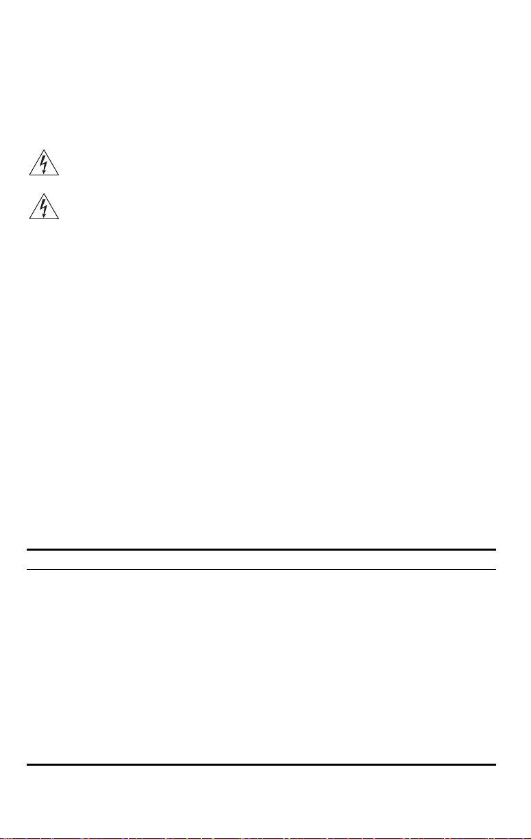
The figures below show the mounting bracket being mounted to a wall, and then a cable
being routed through the large opening on the back of the mounting bracket.
C
radl
e
Installing the mounting bracket
Routing a cable
4 Connect the Ethernet cable (and power cable, if applicable) to the port(s) on the
front of the access point.
5 Snap the access point onto the mounting bracket.
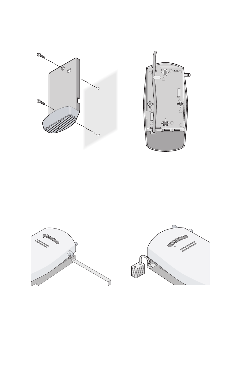
To install the locking bar, push the locking bar through the opening in the side of the
mounting bracket until the hole on the locking bar is exposed. Insert a lock (not provided)
through the hole on the locking bar, and then close the lock to secure it in place.
.11a
.11g
.100
.10
Inserting the locking bar
Securing the bar with a lock
.10
.100
.11g
.11a
Page 6

Tabletop Mounting
To install the access point on a flat surface such as a table or desktop:
CAUTION: Do not place the access point on any type of metal surface. Select a location that
is clear of obstructions and provides good reception.
1 Remove the backing from the four rubber feet and attach them on the bottom of
the mounting bracket that is attached to the access point.
2 Place the access point on the table.
3 Connect the Ethernet cable (and power cable, if applicable) to the port(s) on the
front of the access point.
5 Connecting the Access Point to a Switch
3Com recommends that you install and configure the 3Com Wireless LAN switch before installing the
access point. If the switch is already installed and configured for the access point, you can immediately
verify the cable connection when you plug the cable into the access point.
WARNING: Do not connect or disconnect cables or otherwise work with the access point
during periods of lightning activity.
You can connect the access point directly to a 3Com Wireless LAN Switch port or indirectly to
3Com
Wireless LAN switches through an intermediate Layer 2 or Layer 3 network. In either case, use
Category 5 cable with straight-through signaling for each access point connection.
• To connect the access point directly to a 3Com Wireless LAN Switch, configure the switch port
as an AP2750 access point and then insert the cable into the switch and verify the link.
• To connect the access point indirectly to a 3Com Wireless LAN Switch through the network,
configure a Distributed Access Point connection on the switch.
Note: For instructions on configuring the access point, see the Mobility System
Configuration Guide or the 3Com Wireless LAN Switch Reference Manual.
Page 7

6 Checking the LED Indicators
When the access point is connected to power, LEDs indicate activity as follows (solid LED indicates
connection; blinking LED indicates activity):
LED Color Indicates
POWER
11a
11b/g
100
Power Green
10
11a Green
11b/g Green
100 Green
10 Green
Off
Off
Off
Off
Off
The access point is powered up
and operating normally.
The access point is not receiving
power or there is a fault with the
power supply.
The access point has WLAN
frame transmission over the
802.11a 5.3 GHz radio band.
No link is present.
The access point has WLAN
frame transmission over the
802.11g 2.4 GHz radio band.
No link is present.
The access point has a 100 Mbps
Fast Ethernet connection.
No link is present.
The access point has a 10 Mbps
Ethernet connection.
No link is present.
Troubleshooting
Refer to the Mobility System Configuration Guide or to the 3Com Wireless LAN Switch Reference
Manual to obtain the access point status.
Page 8

Copyright © 2004 3Com Corporation. All rights reserved. 3Com and the 3Com logo are registered
trademarks of 3Com Corporation. All other company and product names may be trademarks of the
respective companies with which they are associated.
DIA27507-5AAA01
Published October 2004
Page 9

R
EGULATORY INF
C
AUTION
: E
XPOSURE
USA - R
ADIO FREQUENC
USA-F
ED
ERAL COMMUNICATIONS COMMISSION
ORMATION
TO RADIO FREQUENC
Y RE
The 3Com AP2750 Managed Access Point (3CRWX275075A)
with th
device complies
This
prod
Li
cense.
This
prod
modification
This product must be installed by a professional technician/installer.
This device generates a
exposure gu
maintain
This device must not
The in
emit RF field in excess of He
fr
om Health Canada’s w
This product must maintain a minimum body to antenna distance of 20 cm. Under these conditions this
product will meet the Basic Restriction limits of 1999/519/EC [Council Recommendation of 12 July 1999
on the limitation of exposure of the general public to electromagnetic fields (0 Hz to 300 GHz)].
QUIREMENT
This
device is for
range.
Hi
gh power radars are allo
radar stations
This
device compl
This device may not cause
in
cludi
This
equipment has been tested and fo
Part 15 of FC
in a re
in
stalled and used in ac
co
mmunicati
is equipment do
th
tu
ning th
the followin
■
Reor
■
Increase
■
Co
■
Consult the dealer or
The user may find th
The Interference Handb
This
booklet is available from th
004-000-0034504.
3C
om is not res
devi
ces included with this 3C
attachment of c
The correction of interference caused by s
th
e res
e manufacturer’s ins
with th
uct con
uct does no
s will invalidate 3C
Y RADIATION
idelines for an
ing a minimum body to antenn
stal
ler
of
this
S
.
can caus
tructions as described in the us
e following radio frequ
tains encrypti
on. It is
unlawful to export out of the U.S. without obtaining a U.S. Export
t contain any user serv
om’s warranty and all applicab
.
nd radiates radi
uncont
be co-located
radio equipment
ebsite w
indoor use only when usin
cated as
e interference with and/or
o-frequen
rolled envir
or op
must ensure
alth Canada limit
ww.
hc-sc.g
primary
ency an
d safety standards.
iceable c
omponents
cy energy.
onment, this
a distance of 20 cm (app
erated in c
onju
that the antenn
s for th
e general popu
c.ca
/rpb.
g channels 36, 40, 44 or 48 in th
us
ers
of the 5.
damage this devi
(FCC)
ies
with part 15 of
ng interference that
C Rules. These limit
sident
ial instal
lation. This
cordance wi
ons. However,
es cause harmfu
e equipment off an
g meas
ures:
ient or relocate the receiving antenna
the distance between the equi
nnect the equipment to outlet on a circuit different
an experie
e foll
ook
pon
sible fo
onnecting cables
pons
ibi
lity of the us
the F
CC Rules.
harmful interference,
ma
y caus
e un
desired operat
und to co
s are designed to provide reasonable protec
equipment generates, uses, and can radiate radi
th the instructions, it
there is
no guarantee t
l interference to ra
d on, th
e us
er is enco
nced radio/TV tec
owin
g booklet prepared
e U.S. Government Prin
r any radio or televis
om
AP2750 Managed Access Point (3CRWX275075A), or the s
and equ
er.
Operation is subject to th
and (2) this devi
mply with the limits for
hat in
dio or televisi
uraged to try and correct the interferenc
pment and the receiver
hnician for help
by the Federal C
ting Offi
ion in
terference caus
ipment other than specified
uch unaut
hor
must
er d
In or
equipment must be installed and operated wh
nctio
25 t
ion.
may caus
terference will
fro
ized modification,
be installed and used in strict
ocumentation
. Any unauthor
le regulatory cert
der to comply with F
rox
n with any other
o 5.35 GHz and
ce must
m that to which
ce, Wash
that co
mes with the pr
ized product changes or
ific
atio
CC radio-frequency
imately 8 in.).
antenna or transmit
a is located o
ce.
e harmful interference to radio
on receptio
ommuni
by 3C
r po
lation;
accept any interference received,
a Clas
no
ington, D.C. 2040
ed by un
substitut
inted s
cons
ult Safety Code 6,
e 5.
15 to 5.
5.
65 t
o 5.85
e foll
owi
s B digital device, pu
tion against harmful interference
o frequency
t o
ccu
r in a particular installation.
n, wh
ich can be determ
the
receiver is connected
cations Commission helpful:
aut
horized mo
om.
ion or attachment wi
ns and
appr
uch that it does not
25 GHz frequency
GHz bands.
ng two co
nditi
energy. If no
e by one or
2. Stock No.
dification of the
acco
rdance
oduc
t. This
ovals.
ter.
obtainable
Thes
ons
: (1)
rsuant to
ined by
more of
ubs
titut
ll be
ile
e
t
If
ion or
Page 10

M
AN
UFACTURER’S DECLA
RATION
OF CONFO
RMITY
3C
om Corp
oration
35
0 Campus Drive
Marlborough,
(
800)
527-8677
Date:
November 8, 2004
Declares
that the Product:
Brand Name: 3Com Cor
M
odel Number: AP2750
Equi
pmen
Complies with Part 15 of
may not cause harmful interferen
in
terference that may caus
MA 017
52-3064,
poration
t Ty
pe: AP2750 Managed Access Point
the F
e undesired operation.
USA
CC rules.
Operation is subject to th
ce, and (2
) this
device must accept any interference received,
3Com AP2750 Managed Access Point
Model AP2750
e foll
owi
ng two co
nditi
ons
: (
1) this devic
inclu
ding
e
Page 11

C
ANADA
– I
NDUSTRY CANADA
I
NDUSTRY CANADA
A
VIS
DE CON
S
AFETY COMPLIA
(IC) E
FORM
ITÉ À LA RÉGLEME
NCE NOT
(IC)
This
device compl
Operation is subject to th
device
must accept any interference, inc
devi
ce.”
L ‘ utilisation de ce disp
br
ouillage et (2) l’ utilisateur
ce br
ouillage est
The term "I
specifications were met.
To reduc
th
co
in
in
Pour
l'
interieur et devrait etre
(
ou s
Hi
radar stations
MISSIONS COMPLIANC
This Class
NTAT
Cet appareil numérique de
C" before the eq
e potential radi
e equivalent isot
mmunicati
doors
an
d away fr
stalled ou
tdoor
empech
on antenne d'emissi
gh power radars are allo
B digital apparatus
ION D’INDUSTRIE CANADA
ICE
This
device has been tested and certi
on
ly in Informat
■
UL
Standard 60950 (3rd Editi
■
CAN/CSA C22.
■
IEC 609
■
50 or 60950-1
EN 60950 or 60950-1
ies
with RSS 210 of Indus
e foll
owin
ositif est
auto
susceptible de compromettre le f
on. To prevent radio interference to the licensed serv
s is s
er que
can caus
E STATEMENT
ion Tec
du dispositif do
uipment cert
o inte
ropicall
2 No.
rferenc
y radiated power (EIRP) is not more than that required for s
om wind
ows
ubject to licens
cet appareil cause d
place lo
in des fenetres afin de
on) es
t installe a l'exterieur, il
cated as
e interference with and/or
comp
la classe B est confo
hnol
ogy Equipment which has
on)
60950 or 60950-1
try Canada.
g two co
luding
risé
e seulem
ification num
e to
other us
to prov
ide maxi
ing.
u brou
primary
us
lies with Canadian ICES-003.
fied ac
cording to the follo
or 60950-1
nditions: (
1) this device may not caus
interference that may caus
ent a
ux co
it étre pr
êt à accepter t
oncti
onnement du disposit
ber only sign
ers, the
mum shield
illage au se
Four
doit
ers
of the 5.
damage this devi
rm à la no
been
nditi
antenn
ing.
rvice faisant l'objet d'une licence, il doit et
nier un ecram de
faire l'objet d'une
25 t
o 5.35 GHz and
rme NMB-
wing
tested to thes
e interference, and (2)
e undesired operati
ons suivantes: (1) il ne do
out b
roui
llage
radioélectrique
if.
ifies
that the
Indus
a t
ype an
d its
gain s
ice, this device is intended to be operated
Equ
ipment (o
r its
transmit
blin
dage maximal. Si le matriel
licen
ce.
5.
ce.
003 du Canada.
safety stan
65 t
dards and
e or other equivalent stan
on of this
it pas
pro
duire de
reçu
try Canada technical
houl
d be so c
uccessful
o 5.85 GHz bands.
hos
antenna)
is intended
re util
dards:
, même si
en that
that is
Thes
fo
th
is
ize
r use
a
e
Page 12

E
UROPE
– EU D
ECLARATION
OF CONFO
RMITY
E
UROPE
- D
ECLA
RATION
OF CONFO
Markin
g by the ab
pr
ovisions of the R&TTE Directive of the European Union (1
co
nfor
mance standards:
EN30
0 328, EN
NOTE: To ensure pr
pr
oduc
t is
Configuration Guide.
RMITY
IN LAN
English Hereby, 3Com Corporation, declares that this RLAN device is in
Finnish 3Com Corporation vakuuttaa täten että RLAN device tyyppinen laite
Dutch Hierbij verklaart 3Com Corporation dat het toestel RLAN device in
French Par la présente 3Com Corporation déclare que l'appareil RLAN
ove symb
301 893
oduc
installed. Refer to the Wireless LAN Mobility System, Wireless LAN Switch and Controller
GUAGES OF THE EUROPEA
ol indicates
, EN301 489-17
t operation is
compliance with the essential requirements and other relevant
provisions of Directive 1999/5/EC.
on direktiivin 1999/5/EY oleellisten vaatimusten ja sitä koskevien
direktiivin muiden ehtojen mukainen.
overeenstemming is met de essentiële eisen en de andere
overeenstemming is met de essentiële eisen en de andere
relevante bepalingen van richtlijn 1999/5/EG
relevante bepalingen van richtlijn 1999/5/EG
Bij deze verklaart 3Com Corporation dat deze RLAN device voldoet
Bij deze verklaart 3Com Corporation dat deze RLAN device voldoet
aan de essentiële eisen en aan de overige relevante bepalingen
aan de essentiële eisen en aan de overige relevante bepalingen
van Richtlijn 1999/5/EC.
van Richtlijn 1999/5/EC.
device est conforme aux exigences essentielles et aux autres
dispositions pertinentes de la directive 1999/5/CE
Par la présente, 3Com Corporation déclare que ce RLAN device est
conforme aux exigences essentielles et aux autres dispositions de
la directive 1999/5/CE qui lui sont applicables
compl
iance with the Essential Requirements and other relevant
, EN60950
in compliance with
N COMM
verklaart 3Com Corporation dat het toestel RLAN device in
999/5/EC). This
local regulations, select the c
UNITY
equipment meets the following
ount
ry in whi
ch the
Swedish Härmed intygar 3Com Corporation att denna RLAN device står I
Danish Undertegnede 3Com Corporation erklærer herved, at følgende
German Hiermit erklärt 3Com Corporation, dass sich dieser/diese/dieses
Greek
Italian Con la presente 3Com Corporation dichiara che questo RLAN
Spanish Por medio de la presente 3Com Corporation declara que el RLAN
överensstämmelse med de väsentliga egenskapskrav och övriga
relevanta bestämmelser som framgår av direktiv 1999/5/EG.
udstyr RLAN device overholder de væsentlige krav og øvrige
relevante krav i direktiv 1999/5/EF
Managed Accces Point in Übereinstimmung mit den grundlegenden
Anforderungen und den anderen relevanten Vorschriften der
Richtlinie 1999/5/EG befindet". (BMWi)
Hiermit erklärt 3Com Corporation die Übereinstimmung des
Gerätes RLAN device mit den grundlegenden Anforderungen und
den anderen relevanten Festlegungen der Richtlinie 1999/5/EG.
(Wien)
ΜΕ ΤΗΝ ΠΑΡΟΥΣΑ 3Com Corporation ∆ΗΛΩΝΕΙ ΟΤΙ RLAN
device ΣΥΜΜΟΡΦΩΝΕΤΑΙ ΠΡΟΣ ΤΙΣ ΟΥΣΙΩ∆ΕΙΣ ΑΠΑΙΤΗΣΕΙΣ
ΚΑΙ ΤΙΣ ΛΟΙΠΕΣ ΣΧΕΤΙΚΕΣ ∆ΙΑΤΑΞΕΙΣ ΤΗΣ Ο∆ΗΓΙΑΣ 1999/5/ΕΚ
device è conforme ai requisiti essenziali ed alle altre disposizioni
pertinenti stabilite dalla direttiva 1999/5/CE.
device cumple con los requisitos esenciales y cualesquiera otras
disposiciones aplicables o exigibles de la Directiva 1999/5/CE
Page 13

E
UROPE
– R
ESTRI
CTIONS
FOR USE OF
Portuguese 3Com Corporation declara que este RLAN device está conforme
Malti Hawnhekk, 3Com Corporation, jiddikjara li dan RLAN device
Estonian Käesolevaga kinnitab 3Com Corporation seadme RLAN device
Hungarian
Slovak 3Com Corporation týmto vyhlasuje, že RLAN device spĺňa základné
Czech 3Com Corporation tímto prohlašuje, že tento RLAN device je ve
Slovene Šiuo 3Com Corporation deklaruoja, kad šis RLAN device atitinka
Lithuanian Šiuo 3Com Corporation deklaruoja, kad šis RLAN device atitinka
Latvian Ar šo 3Com Corporation deklarē, ka RLAN device atbilst Direktīvas
A copy of the signed Declaration of Conformity can be downloaded from the Product Support web page for the
AP2750 (
3CRWX275075A)
2.4GHZ F
• This device may be operated indoors or outdoors in all countries of the European Community
• In Italy the end-user must apply for a license from the national spectrum authority to operate this
• In Belgium outdoor operation is only permitted using the 2.46 – 2.4835 GHz band: Channel 13.
• In France outdoor operation is only permitted using the 2.4 – 2.454 GHz band: Channels 1 – 7.
REQU
using the 2.4GHz band: Channels 1 – 13, except where noted below.
device outdoors.
com os requisitos essenciais e outras disposições da Directiva
1999/5/CE.
jikkonforma mal-ħtiġijiet essenzjali u ma provvedimenti oħrajn
relevanti li hemm fid-Dirrettiva 1999/5/EC
vastavust direktiivi 1999/5/EÜ põhinõuetele ja nimetatud direktiivist
tulenevatele teistele asjakohastele sätetele.
Alulírott, 3Com Corporation nyilatkozom, hogy a RLAN device
megfelel a vonatkozó alapvetõ követelményeknek és az 1999/5/EC
irányelv egyéb elõírásainak.
požiadavky a všetky príslušné ustanovenia Smernice 1999/5/ES.
shodě se základními požadavky a dalšími příslušnými ustanoveními
směrnice 1999/5/ES.
esminius reikalavimus ir kitas 1999/5/EB Direktyvos nuostatas.
esminius reikalavimus ir kitas 1999/5/EB Direktyvos nuostatas.
1999/5/EK būtiskajām prasībām un citiem ar to saistītajiem
noteikumiem.
at http://www.3com.com.
ENCIES
IN EUROPEA
N COMMU
NITY COUNTRI
ES
Page 14

E
UROPE
– R
ESTRI
CTIONS
FOR USE OF
5GHZ F
REQUENCIES IN EUROPEA
N COMMU
NITY COUNTRIES
Allowed Frequency Bands Allowed Channel Numbers Countries
5.15-5.25GHz 36, 40, 44, 48 Austria
5.15-5.35GHz 36, 40, 44, 48, 52, 56, 60, 64 Belgium, Cyprus, Czech Republic, France,
5.15-5.35 & 5.470-5.725GHz 36, 40, 44, 48, 52, 56, 60, 64, 100, 104, 108,
112, 116, 120, 124, 128, 132, 136, 140
• This device may be not be operated outdoors when using the bands 5150-5350MHz (Channels
36, 40, 44, 48, 52, 56, 50, 64).
• In Italy the end-user must apply for a license from the national spectrum authority to operate this
device outdoors.
To rema
•
•
•
•
in in confo
2.
4GHz and 5GHz channel li
operation is occu
the Managed Access Point at
e
less netw
the wir
The 5GHz Turbo mode feature is not allo
This
device must be us
the 5GHz
presence of nearby radar operat
The
device. The Ac
radar.
You may c
sure the Access Point device(s)
en
rmance with European spectrum us
mitation
that location and co
ed with
the
device will avoid operating
oint’s radar detect
ult wit
h the l
bands.
rring outside of
ork.
This
cess P
ons
s apply. The us
th
e allowabl
radar detecti
ion may result
ion feature will automa
ocal technical s
ar
e properly configured fo
Hungary, Liechtenstein, Slovakia, Switzerland
Bulgaria, Denmark, Estonia, Finland, Germany,
Greece, Iceland, Ireland, Italy, Latvia, Lithuania,
Luxembourg, Malta, Netherlands, Norway, Poland,
Portugal, Slovenia, Spain, Sweden, U.K.
age laws fo
er sh
e frequencies as lis
nsult the l
wed for operation in an
on feat
ure required
on a ch
in temp
upp
ort staff responsible for the wireless netw
r Wireless LAN operat
ould check th
annel occ
orary in
r European Community operatio
e cur
ted ab
ove, the user
ocal techni
cal support staff
y Eu
ropean Community cou
fo
r Eur
upied by
terruption in co
tic
ally restart op
rent channel of operati
opean Co
any radar system in the area
mmun
eration on a channel free of
must cease operating
mmunity op
ion, th
resp
icati
e above
on. If
onsible for
ntry.
eration in
ons
of this
ork to
n.
.
 Loading...