

Page 1

HPE 5920 & 5900 Switch Series
TRILL Configuration Guide
P
Software
Document version: 6W100-20171115
art number: 5200-4558
version: Release 243x
Page 2

© Copyright 2017 Hewlett Packard Enterprise Development LP
The information contained herein is subject to change without notice. The only warranties for Hewlett Packard
Enterprise products and services are set forth in the express warranty stat ement s ac c om pa ny i ng such
products and services. Nothing herein should be construed as constit ut i ng an add it i onal warranty. Hewlett
Packard Enterprise shall not be liable for technical or editorial err o rs or omis s ions contained herein.
Confidential computer software. Valid license from Hewlett Packard Enterprise required for possession, use, or
copying. Consistent with FAR 12.211 and 12.212, Commercial Computer Software, Computer Software
Documentation, and T echnical Data for Commercial Items are licensed to the U.S. Government under vendor’s
standard commercial license.
Links to third-party websites take you outside the Hewlett Packard Ent erpr is e we bsite. Hewlett Packard
Enterprise has no control over and is not responsible for information outside the Hewlett Packard Enterprise
website.
Acknowledgments
Intel®, Itanium®, Pentium®, Intel Inside®, and the Intel Inside lo go ar e trademarks of Intel Corporation in the
United States and other countries.
Microsoft® and Windows® are either registered trademarks or t rade marks of Microsoft Corporation in the
United States and/or other countries.
Adobe® and Acrobat® are trademarks of Adobe Systems Incorporated.
Java and Oracle are registered trademarks of Oracle and/or its affiliates.
UNIX® is a registered trademark of The Open Group.
Page 3

Contents
Configuring TRILL ··························································································· 1
Overview ···························································································································································· 1
Basic concepts ··········································································································································· 1
TRILL frame formats ·································································································································· 1
How TRILL works ······································································································································· 2
TRILL forwarding mechanisms ·················································································································· 3
Ping TRILL and tracert TRILL ···················································································································· 5
Protocols and standards ···························································································································· 7
Configuration restrictions and guidelines ··········································································································· 7
TRILL configuration task list ······························································································································· 8
Enabling TRILL ·················································································································································· 9
Configuration restrictions and guidelines ··································································································· 9
Configuration procedure ··························································································································· 10
Configuring the system ID and nickname for an RB ························································································ 10
Configuring the link type of a TRILL port ········································································································· 11
Configuration procedure ··························································································································· 11
Configuring the DRB priority of a TRILL port ··································································································· 11
Setting the link cost for a TRILL port ················································································································ 11
Configuring announcing VLANs and the designated VLAN ············································································· 12
Configuring TRILL timers ································································································································· 13
Configuring TRILL LSP parameters and features ···························································································· 14
Setting TRILL LSP parameters ················································································································ 14
Enabling TRILL LSP fast advertisement ·································································································· 15
Enabling TRILL pseudonode bypass ······································································································· 15
Setting the SPF algorithm parameters ············································································································· 16
Configuring TRILL distribution trees ················································································································ 16
Setting basic distribution tree parameters ································································································ 16
Enabling TRILL distribution tree multithread calculation ·········································································· 17
Enabling load balancing over TRILL distribution trees ············································································· 17
Configuring TRILL ECMP routes ····················································································································· 18
Enabling incremental flush for TRILL multicast routing entries ········································································ 18
Enabling logging of TRILL neighbor changes ·································································································· 19
Configuring SNMP for TRILL ··························································································································· 19
Enabling TRILL to forward traffic from EVB S-channels ·················································································· 20
Configuring TRILL GR ····································································································································· 20
Associating a TRILL port with a track entry ····································································································· 21
Using ping TRILL and tracert TRILL to test network connectivity ···································································· 21
Displaying and maintaining TRILL ··················································································································· 22
TRILL configuration example ··························································································································· 22
Network requirements ······························································································································ 22
Configuration procedure ··························································································································· 23
Verifying the configuration ························································································································ 25
Document conventions and icons ································································· 27
Conventions ····················································································································································· 27
Network topology icons ···································································································································· 28
Support and other resources ········································································ 29
Accessing Hewlett Packard Enterprise Support ······························································································ 29
Accessing updates ··········································································································································· 29
Websites ·················································································································································· 30
Customer self repair ································································································································· 30
Remote support ········································································································································ 30
Documentation feedback ························································································································· 30
Index ············································································································· 32
i
Page 4

Configuring TRILL
•
•
•
•
•
•
•
•
TRansparent Interconnection of Lots of Links (TRILL) uses IS-IS to provide transparent Layer 2
forwarding.
Overview
TRILL combines the simplicity and flexibility of Layer 2 switching with the stability, scalability, and
rapid convergence capability of Layer 3 routing. All these advantages make TRI LL very suitable for
large flat Layer 2 networks in data centers.
Basic concepts
RBridge—Routing bridge (RB) that runs TRILL. RBs are classified into ingress RBs, transit
RBs, and egress RBs, depending on their positions in the TRILL network. A frame enters the
TRILL network through an ingress RB, travels along transit RBs, and leaves the TRILL network
through an egress RB, as shown in
TRILL network—A Layer 2 network comprised of RBs, as shown in Figure 3.
System ID—Unique identifier of an RB in the TRILL network. The system ID is 6-byte.
Nickname—Address of an RB in the TRILL network. The nickname is 2-byte.
Link State Database—The LSDB contains all link state information in the TRILL network.
Link State Protocol Data Unit—An LSP describes local link state information and is
advertised between neighbor devices.
Designated Routing Bridge (DRB)—Similar to the designated IS (DIS) in IS-IS, a DRB exists
in a broadcast network. It helps simplify network topology, and assigns AVFs and appointed
ports for the VLANs on each RB in the broadcast network.
Appointed VLAN-x Forwarder (AVF) and appointed port—T o avoid loops, TRILL requires all
traffic of a VLAN on a broadcast network to enter and leave the TRILL network through the
same port of an RB. The RB is the VLAN's AVF, and the port is the VLAN's appointed port.
Figure 2.
For more information about LSDB, LSPDU, and DIS, see Layer 3—IP Routing Configuration Guide.
TRILL frame formats
TRILL frames include protocol frames and data frames.
TRILL protocol frames include TRI LL Hello, LSP, CSNP, PSNP, MTU-probe, and MTU-ack. These
protocol frames use 802.1Q encapsulation and have a fixed destination multicast address
0180-C200-0041.
TRILL data frames have a specific format, as shown in Figure 1. A TRILL header and an outer
Ethernet header are added to the original Ethernet frame.
1
Page 5
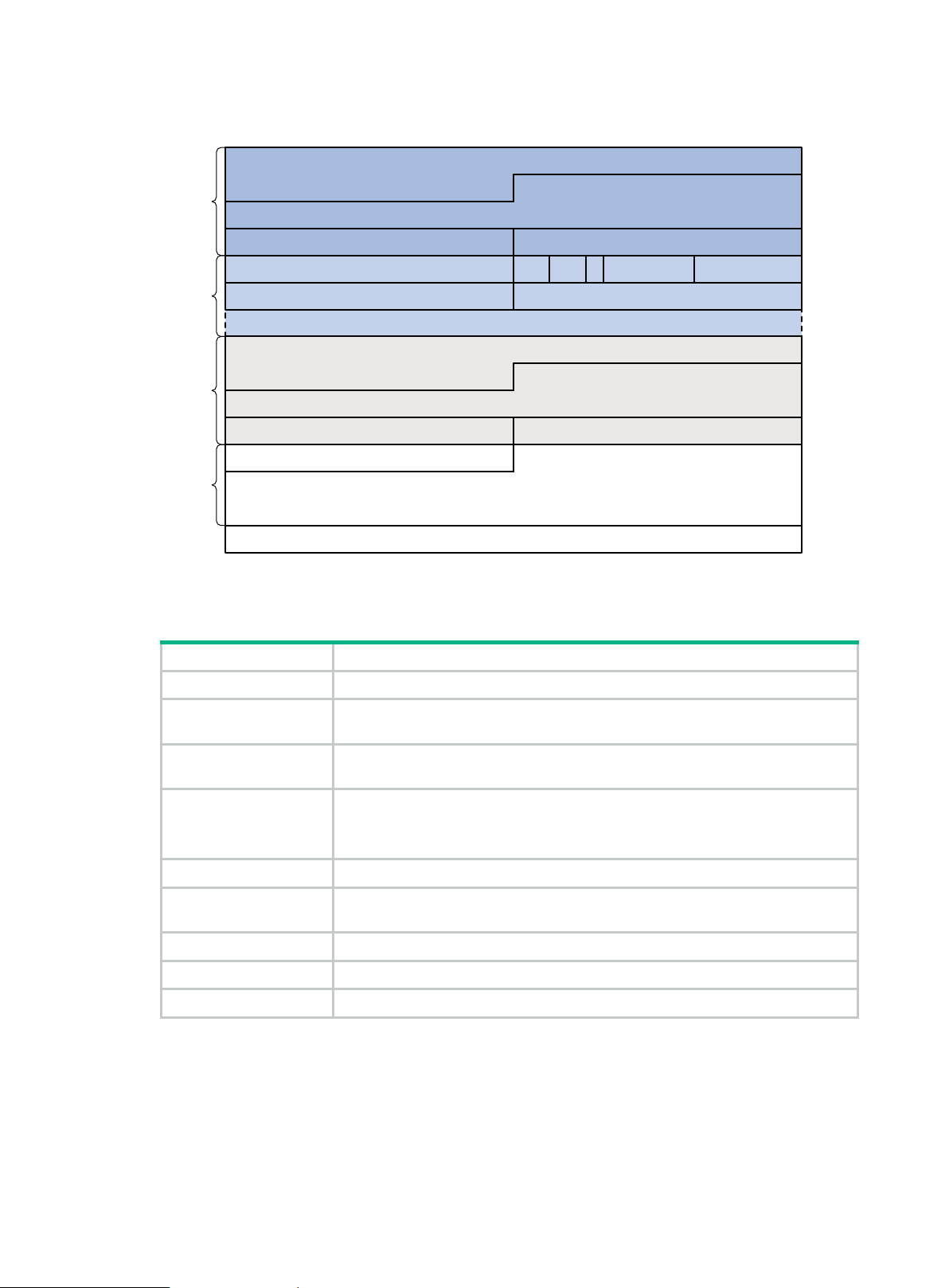
Figure 1 TRILL data frame format
Field
Description
Options
Outer Destination MAC Address
0 32
Outer Source MAC Address
Ethertype = 802.1Q
Outer VLAN Tag Information
Ethertype = TRILL
New FCS
16
V
Inner Destination MAC Address
Inner Source MAC Address
Ethertype = 802.1Q Inner VLAN Tag Information
Outer
Ethernet
header
Egress RB Nickname Ingress RB Nickname
R M Op-Length
Hop Count
TRILL
header
Inner
Ethernet
header
Original Ethernet Payload
Ethertype of Original Ethernet Payload
Payload
Table 1 describes the fields in the TRILL header.
Table 1 TRILL header fields
Ethertype The Ethertype is fixed to 0x22F3.
V
R
Version number, which is 0. When an RB receives a TRILL frame, it checks the V
field and drops the frame if the V field is not 0.
Reserved for future extension. An ingress RB sets the R field to 0 when adding a
TRILL header. Transit RBs and egress RBs ignore the field.
Multidestination attribute:
M
• 0—Known unicast frame.
• 1—Multidestination frame (multicast, broadcast, or unknown unicast frame).
Op-Length Length of the Options field. 0 indicates that the Options field does not exist.
Hop Count
Hop count, which is used to avoid loops. An RB drops a TRILL frame whose hop
count is decremented to 0.
Egress RB Nickname Nickname of the egress RB.
Ingress RB Nickname Nickname of the ingress RB.
Options Options field. This field exists when the Op-Length field is non-zero.
How TRILL works
TRILL establishes and maintains adjacencies between RBs by periodically advertising Hello frames,
distributes LSPs among RB neighbors, and generates an LSDB for all RBs in the network. Based on
the LSDB, each RB uses the SPF algorithm to calculate forwarding ent ri es destined to other RBs.
2
Page 6
TRILL forwarding mechanisms
•
•
VLAN 10 VLAN 200
VLAN 300
VLAN
10
Ingress RB
RB 1
S1 S2
Ethernet frame TRILL frame TRILL frame
Ethernet frame
Egress RB
RB 3
Transit
RB
RB 2
Ingress RB =
RB 1
Outer VLAN
= 200
Egress RB = RB 3
Outer S-MAC
= RB 1
Outer D-MAC = RB 2
Payload
Inner VLAN = 10
Inner S-MAC = S1
Inner D
-MAC =
S2
Ingress RB = RB 1
Outer VLAN =
300
Egress RB = RB
3
Outer S-MAC = RB 2
Outer D-
MAC = RB 3
Payload
Inner VLAN = 10
Inner S-
MAC = S
1
Inner D-MAC = S
2
Payload
Inner VLAN = 10
Inner S-MAC = S1
Inner D-MAC = S2
Payload
Inner VLAN
= 10
Inner S-MAC = S1
Inner D-MAC
= S2
Unicast frame
Different types of frames are forwarded by using different forwarding mechanisms. The following
sections describe these mechanisms.
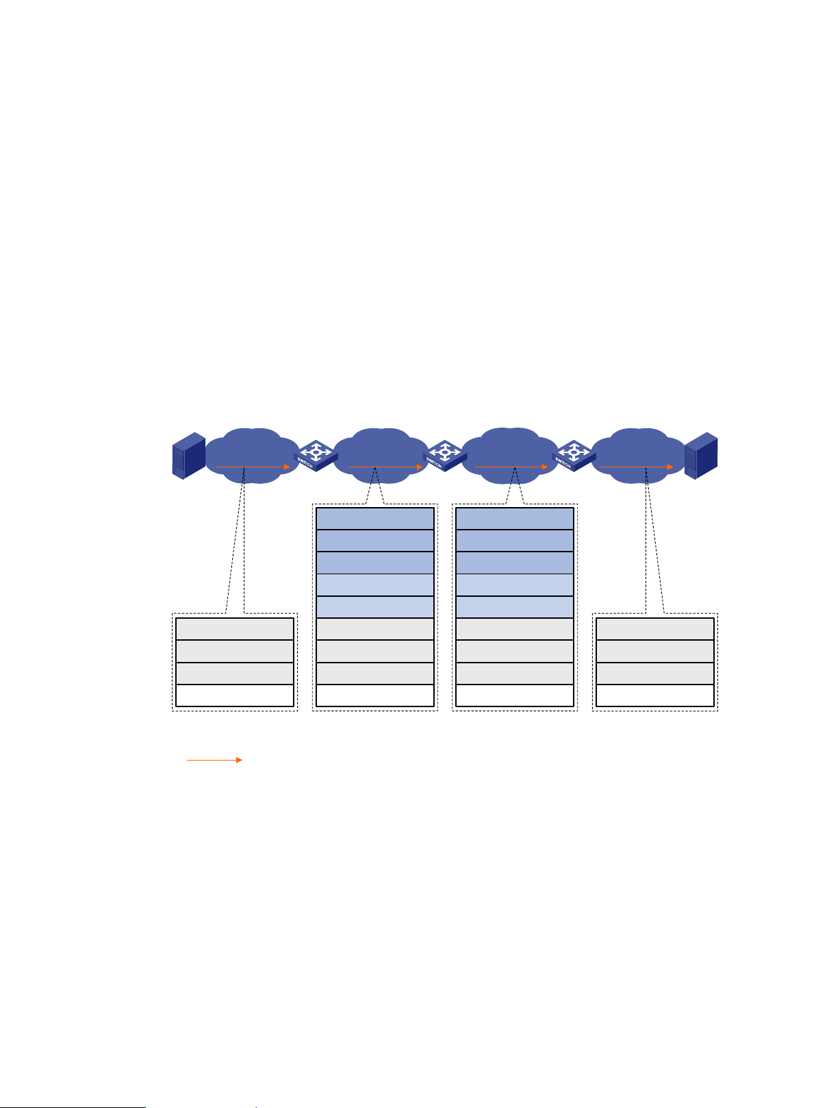
Unicast frame forwarding mechanism
As shown in Figure 2, a unicast frame is forwarded as follows:
1. When a unicast frame enters the TRILL network, the ingress RB encapsulat e s the orig in al
Ethernet frame with the following headers:
2. A TRILL header (similar to an IP header).
3. An outer Ethernet header (similar to the Ethernet header of a regular Ethernet fra me).
4. RBs forward the frame hop by hop according to the egress RB nickname in the TRILL header in
the same way routers forward IP packets. Each hop replaces the outer Ethernet header with an
appropriate outer Ethernet header, and decrements the hop count in the TRILL header.
5. Upon receiving the TRILL frame, the egress RB de-encapsulates it to obt a in the orig inal
Ethernet frame, and sends the frame to the target device.
Figure 2 Unicast frame forwarding flow
The outer Ethernet header enables traditional Ethernet switches to forward T R I L L f rames and
connect RBs.
Multidestination frame forwarding mechanism
In a TRILL network, RBs perform the following tasks:
Compute a TRILL distribution tree for each VLAN based on the LSDB.
Guide the forwarding of multidestination frames in each VLAN b y using its TRILL distribution
tree.
As shown in Figure 3, when a multicast frame from VLAN 10 enters the TRILL network, RB 1, which
is an ingress RB, encapsulates the multicast frame into a TRILL frame. In the frame, the egress RB is
RB 2, the root bridge of the TRILL distribution tree for VLAN 10, and the destination MAC address is
multicast address 0180-C200-0040. When the frame arrives at the root bridge, it is distributed
throughout the TRILL distribution tree. Then, the TRILL frame is de-encapsulated by RB 3 and sent
3
Page 7
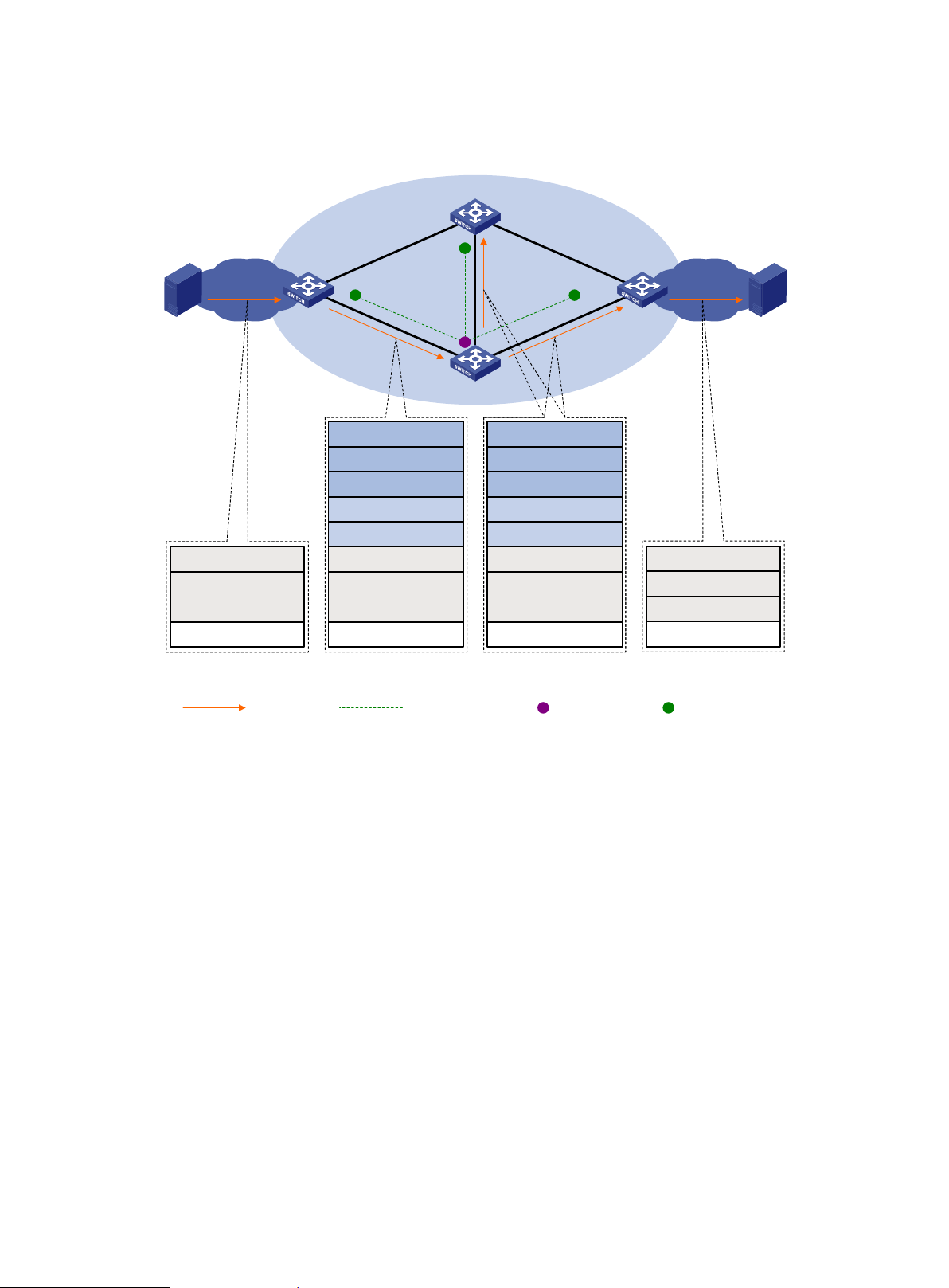
to the destination station S2. Because the network segment where RB 4 resides does not have a
VLAN 10
VLAN 10
S1 S2
VLAN 200
TRILL network
RB 1
Ethernet frame
Payload
Inner VLAN = 10
Inner S-MAC = S1
Inner D-MAC = Multi
TRILL frame
Ingress RB = RB 1
Outer VLAN = 200
Egress RB = RB 2
Outer S-MAC = RB 1
Outer D-MAC = All RBs
Payload
Inner VLAN = 10
Inner S-MAC = S1
Inner D-MAC = Multi
TRILL frame
Ingress RB = RB 1
Outer VLAN = 200
Egress RB = RB 2
Outer S-MAC = RB 2
Outer D-MAC = All RBs
Payload
Inner VLAN = 10
Inner S-MAC = S1
Inner D-MAC = Multi
RB 4
RB 3
Ethernet frame
Payload
Inner VLAN = 10
Inner S-MAC = S1
Inner D-MAC = Multi
RB 2
Multicast frame
Distribution tree
of VLAN 10
Root bridge of
distribution tree
Leaf of
distribution tree
receiver of this frame, RB 4 drops the frame.
Figure 3 Multicast frame forwarding flow
TRILL selects distribution trees for forwarding multidestination frames based on the VLANs to which
the frames belong. Because the topologies of TRILL distribution trees are different, traffic can be
load shared. However, equal-cost links are not used for load sharing.
When N equal-cost links exist in the network, each TRILL distribution tree selects the link with the
largest pseudonode ID for forwarding packets. As shown in Figure 4, two equal-cost links exist
between RB 1 and RB 3. Assume the link directly connecting RB 1 to RB 3 has the largest
pseudonode ID. Both the TRILL distribution tree rooted at RB 3 and the TRILL distribution tree rooted
at RB 4 select the link. For more information about pseudonode IDs, see Layer 3—IP Routing
Configuration Guide.
4
Page 8

Figure 4 Multicast ECMP
•
•
Cost = 3
Cost = 2
Cost = 1
RB 1
RB 2 RB 3 RB 4
TRILL distribution trees support Equal Cost Multiple Path (ECMP), also known as multicast ECMP.
When multicast ECMP is enabled, TRILL assigns equal-cost links to multiple TRILL distributions
trees. This improves the load sharing performance.
When N equal-cost links exist in the network, each TRILL distribution tree selects an equal-cost link
for forwarding packets through J mod N in root bridge priority order. J is the priority sequence number
of a TRILL distribution tree and starts from 0.
As shown in Figure 4:
The link directly connecting RB 1 to RB 3 is assigned to the TRILL distribution tree rooted at RB
3.
The link RB 1-RB 2-RB 3 is assigned to the TRILL distribution tree rooted at RB 4.
TRILL distribution trees support fast root switching. When an RB detects that the root of a distribution
tree is unreachable, the RB deletes the LSP of the root from its LSDB. This triggers recalculation of
all distribution trees in the TRILL network. Multidestination traffic is switched to new distribution trees.
Ping TRILL and tracert TRILL
You can use ping TRILL and tracert TRILL to test TRILL network connectivity when network failure
occurs or new RBs are added to the network.
Ping TRILL and tracert TRILL are implemented through the TRILL Operation, Administration, and
Maintenance (OAM) protocol.
Ping TRILL
Use ping TRILL to determine if an RB is reachable.
As shown in Figure 5, the source RB sends OA M echo requests to ping the destination RB. Upo n
receiving the requests, the destination RB responds to the source RB with OAM echo replies. The
source RB outputs statistics about the ping TRILL operation, including the number of sent echo
requests, the number of received echo replies, and the round-trip time. Y ou can measure the network
performance by analyzing the statistics.
5
Page 9
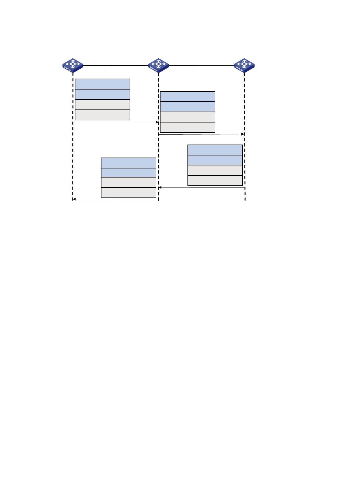
Figure 5 Ping TRILL packet forwarding
RB 1 RB 2 RB 3
ECHO-REQUEST
ECHO-REQUEST
ECHO-REPLY
ECHO-REPLY
Ingress RB = RB 1
Egress RB = RB 3
Hop Count = 63
Sequence number = 1
Ingress RB = RB 1
Egress RB = RB 3
Hop Count = 62
Sequence number = 1
Ingress RB = RB 3
Egress RB = RB 1
Hop Count = 63
Sequence number = 1
Ingress RB = RB 3
Egress RB = RB 1
Hop Count = 62
Sequence number = 1
Tracert TRILL
Tracert TRILL enables retrieval of the nicknames of RBs in the path to a destination RB. In the event
of network failure, use tracert TRILL to test network connectivity and identify failed nodes.
Tracert TRILL operates as shown in Figure 6.
1. RB 1 sends RB 3 an OAM echo request with a hop count value of 0.
2. The first hop RB 2 responds by sending a hop count error notification to the source RB because
the hop count of the request is 0. The notification uses the nickname of RB 2 as the ingress RB.
In this way, RB 1 can get the nickname of the first hop RB.
3. RB 1 sends RB 3 an OAM echo request with a hop count value of 1.
4. RB 2 forwards the request to RB 3 according to the TRILL unicast routing table and decrements
the hop count value by 1.
5. The second hop RB 3 responds to the source RB with a hop count error notificat i on . The
notification uses the nickname of RB 3 as the ingress RB.
6. RB 2 forwards the hop count error notification to RB 1. RB 1 gets the nickname of the second
hop RB 3.
6
Page 10
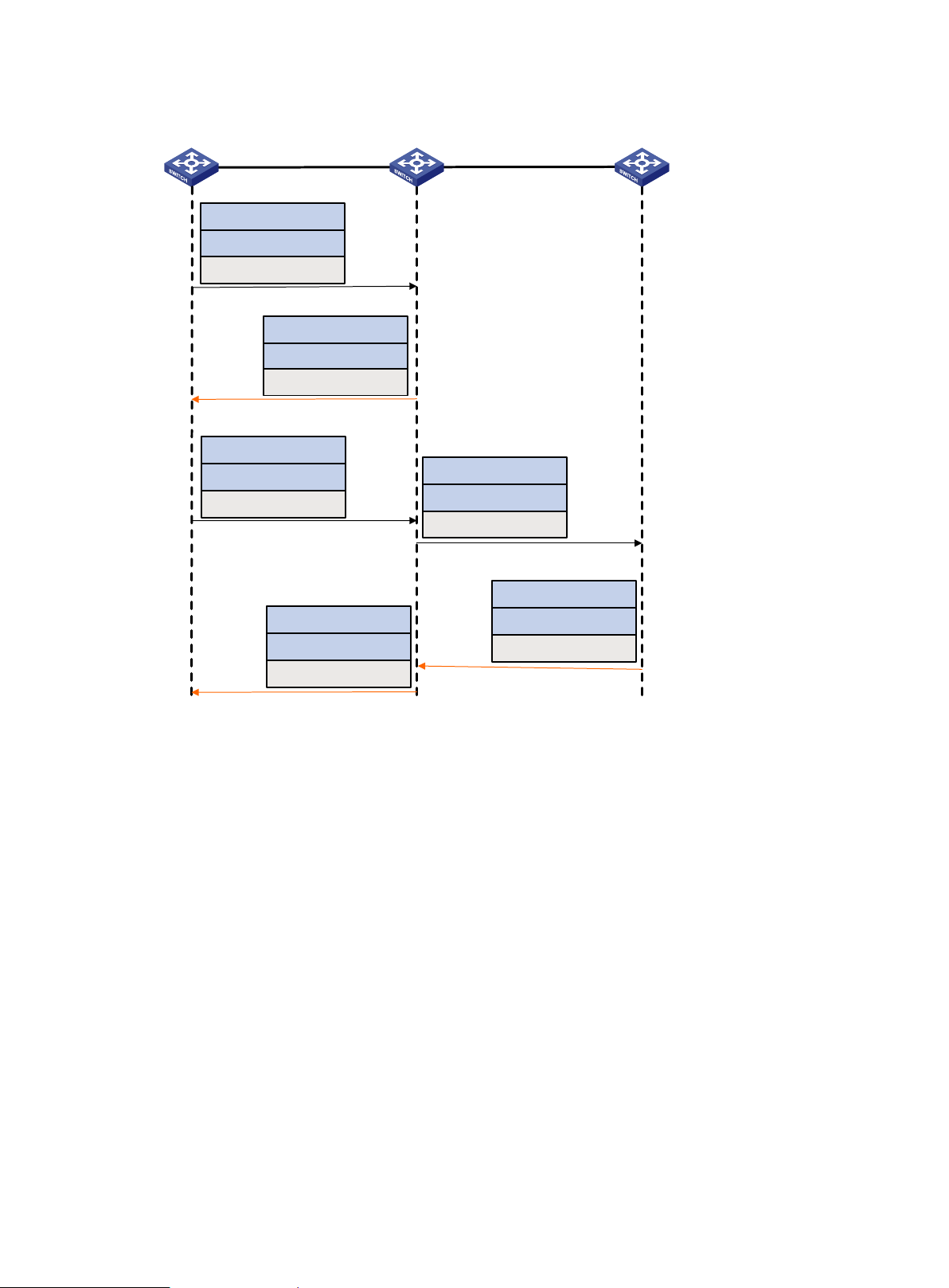
Figure 6 Tracert TRILL packet forwarding
•
•
•
•
•
•
•
RB 1 RB 2 RB 3
ECHO-REQUEST
Ingress RB = RB 1
Egress RB = RB 3
Hop Count = 0
Hop Count = 0 error notification
Ingress RB = RB 2
Egress RB = RB 1
Hop Count = Default
ECHO-REQUEST
Ingress RB = RB 1
Egress RB = RB 3
Hop Count = 1
Hop Count = 0 error notification
Ingress RB = RB 3
Egress RB = RB 1
Hop Count = Default-1
ECHO-REQUEST
Ingress RB = RB 1
Egress RB = RB 3
Hop Count = 0
Hop Count = 0 error notification
Ingress RB = RB 3
Egress RB = RB 1
Hop Count = Default
Protocols and standards
Configuration restrictions and guidelines
RFC 6325, Routing Bridges (RBridges): Base Protocol Specific a t ion
RFC 6326, Transparent Interconnection of Lots of Links (TRILL) Use of IS-IS
RFC 6327, Routing Bridges (RBridges): Adjacency
RFC 1195, Use of OSI IS-IS for Routing in TCP/IP and Dual Environments
RFC 7978, Transparent Interconnection of Lots of Links (TRILL): RBridge Channel Header
Extension
RFC 6905, Requirements for Operations, Administration, and Maintenance (OAM) in
Transparent Interconnection of Lots of Links (TRI LL)
When you configure TRILL, follow these restrictions and guidelines:
Configuration in Layer 2 Ethernet interface view takes effect only on the current port.
Configuration in Layer 2 aggregate interface view takes effect on the current interf ac e and its
member ports. Configuration on the member port of an aggregate interf ac e t ak es effect after
the member port leaves the aggregation group.
7
Page 11

•
•
•
•
•
•
•
Tasks at a glance
To connect a spanning tree network to a TRILL network, make sure the following requirements
are met:
The spanning tree protocol is disabled on TRILL ports.
An edge port is used to connect the spanning tree network to the TRILL network. The edge
port can transit to the forwarding state before DRB election is fini shed. This prevents
multiple DRBs from being elected.
For more information about spanning tree protocols, see Layer 2—L AN Switching
Configuration Guide.
As a best practice, do not enable loop detection on TRILL ports, because TRILL avoids loops.
For more information about loopback detection, see Layer 2—LAN Switching Configuration
Guide.
If IRF is used, retain the IRF bridge MAC address permanently. Otherwise, traffic interruption
might occur after an IRF split. For more information about IRF confi gur ation, see IRF
Configuration Guide.
Do not configure the TPID for VLAN tags on RBs. For more information about TPIDs, see Layer
2—LAN Switching Configuration Guide.
To avoid loops, do not connect multiple TRILL ports of an RB to a broadcast network, because
TRILL ports cannot detect each other when they are on a broadcast network. If there are
multiple TRILL ports, they might be elected as the appointed ports of a VLAN at the same time
and result in loops.
For the TRILL network to forward Layer 3 multidestination traffic correctly, make sure the
following requirements are met:
The IGMP/MLD snooping version must be the same on all RBs.
IGMP or MLD must be enabled on the access-facing VLAN interfaces on gateway RBs to
prevent topology changes from interrupting traffic.
Enabling PIM-DM or IPv6 PIM-DM on core layer and distribution layer devices might cause
multicast traffic duplication. As a best practice, use other Layer 3 multicast protocols.
TRILL configuration task list
(Required.) Enabling TRILL
(Required.) Configuring the system ID and nickname for an RB
(Optional.) Configuring the link type of a TRILL port
(Optional.) Configuring the DRB priority of a TRILL port
(Optional.) Setting the link cost for a TRILL port
(Optional.) Configuring announcing VLANs and the designated VLAN
(Optional.) Configuring TRILL timers
(Optional.) Configuring TRILL LSP parameters and features
(Optional.) Setting the SPF algorithm parameters
(Optional.) Configuring TRILL distribution trees
(Optional.) Configuring TRILL ECMP routes
(Optional.) Enabling incremental flush for TRILL multicast routing entries
(Optional.) Enabling logging of TRILL neighbor changes
(Optional.) Configuring SNMP for TRILL
8
Page 12
Tasks at a glance
(Optional.) Enabling TRILL to forward traffic from EVB S-channels
•
•
•
•
Traditional Ethernet
switch
RB 1
RB 2 RB 3
TRILL enabled port
(Optional.) Configuring TRILL GR
(Optional.) Associating a TRILL port with a track entry
(Optional.) Using ping TRILL and tracert TRILL to test network connectivity
Enabling TRILL
After you enable TRILL on a port, TRILL can operate correctly by using default settings. A port with
TRILL enabled is called a TRILL port.
Configuration restrictions and guidelines
When you enable TRILL, follow these guidelines:
To enable TRILL on a port, first enable TRILL globally.
Enable or disable TRILL on all ports in a VLAN, so that the ports in a VLAN have the same
TRILL status (enabled or disabled).
Do not enable both TRILL and EVB on a port. If the trill evb-support command is not executed
on an EVB-enabled port, make sure the allowed VLANs of the port do not overlap with those of
a TRILL-enabled port. For more information about EVB, see EVB Conf iguration Guide.
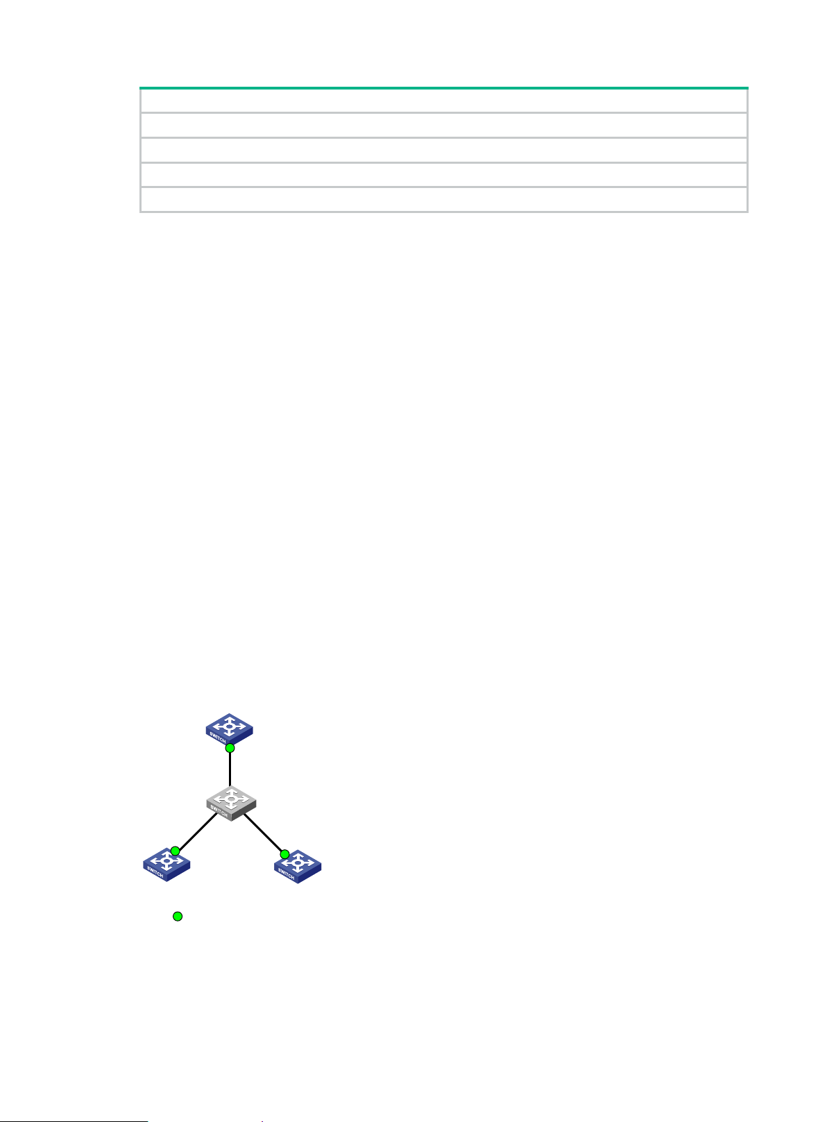
When you set up a TRILL network, avoid the case that multiple TRILL neighbors are
established for one RB port. When you plan a network, avoid the networ k s sh own in
and Figure 8.
Figure 7 shows a typical network where two TRILL neighbors are established for the same
port of an RB.
In Figure 8, because TRILL is not enabled on the port connecting RB 2 to RB 3, the port will
transparently transmit the TRILL Hello frames from RB 3. As a result, two TRILL neighbors
are established for the port connecting RB 1 to RB 2.
Figure 7
Figure 7 Two TRILL neighbors are established for a port (1)
9
Page 13

Figure 8 Two TRILL neighbors are established for a port (2)
Step
Command
Remarks
•
•
Step
Command
Remarks
RB 1 RB 2 RB 3
TRILL enabled port TRILL disabled port
Configuration procedure
To enable TRILL:
1. Enter system view.
2. Enable TRILL globally and
enter TRILL view .
3. Return to system view.
4. Enter Layer 2 Ethernet or
aggregate interface view.
5. Enable TRILL on the port.
system-view N/A
trill
quit N/A
interface interface-type
interface-number
trill enable
By default, TRILL is disabled
globally.
N/A
By default, TRILL is disabled on a
port.
Configuring the system ID and nickname for an RB
The system ID and nickname of an RB are identifiers of the RB in the TRILL network.
System ID—Unique identifier of an RB in the TRILL network. The system ID can be
automatically assigned or manually configured.
Nickname—Address of an RB in the TRILL network. The address can be automatically
assigned or manually configured. When multiple RBs in the TRILL network have the same
nickname, the RB with the highest priority uses the nickname. Whe n t he RBs also have the
same priority, the RB with the highest system ID uses the nickname. The system automatically
assigns new nicknames to the other RBs.
The system resets the TRILL process when the RB's system ID changes.
To configure the system ID and nickname for the RB:
1. Enter system view.
2. Enter TRILL view.
3. Configure the system ID
for the RB.
4. Configure the nickname
for the RB.
system-view N/A
trill N/A
By default, the RB automatically generates
system-id system-id
nickname nickname
[ priority priority ]
10
a system ID based on its MAC address
upon startup.
By default, TRILL automatically assigns
nicknames to RBs, and the priority for a
RB to hold a nickname is 64.
Page 14

Configuring the link type of a TRILL port
•
•
•
Step
Command
Remarks
Step
Command
Remarks
•
•
•
The following link types are available for a TRILL port:
Access—Access ports include access ports without the alone attrib ut e an d ac c e s s por t s with
the alone attribute. Access ports with the alone attribute do not send or receive Hello frames
and do not participate in DRB election or AVF negotiation. Access ports without the alone
attribute can process only local data frames and Hello frames.
Hybrid—A hybrid port combines the attributes of an access port and a trunk port, and can
process local data frames and passing data frames.
Trunk—A trunk port can process passing data frames and some of Layer 2 protocol frames (for
example, LLDP frames), but it cannot process local data frames.
Configuration procedure
To configure the link type of a TRILL port:
1. Enter system view.
2. Enter Layer 2 Ethernet or
aggregate interface view.
3. Configure the link type of the
TRILL port.
system-view N/A
interface interface-type
interface-number
trill link-type { access [ alone ] |
hybrid | trunk }
N/A
By default, the link type of a
TRILL port is access without the
alone attribute.
Configuring the DRB priority of a TRILL port
On a broadcast network, TRILL must elect a DRB. An RB with a higher DRB priority is preferred in
DRB election. When two RBs have the same DRB priority, the RB with a higher MAC address takes
precedence.
To configure the DRB priority of a TRILL port:
1. Enter system view.
2. Enter Layer 2 Ethernet or
aggregate interface view.
3. Configure the DRB priority of
the TRILL port.
system-view N/A
interface interface-type
interface-number
trill drb-priority priority
N/A
By default, the DRB priority of a
TRILL port is 64.
Setting the link cost for a TRILL port
The link cost of a TRILL port can be automatically calculated by the system or manually configured.
A manually configured link cost takes precedence over a calculated link cost.
If no configured link cost exists and automatic link cost calculation is enabled, the calculated link
cost takes effect.
If no configured link cost exists and automatic link cost calculat ion is disabled, the default link
cost of 2000 is used.
11
Page 15

The system automatically calculates the link cost of a TRILL port by using the following formula: link
Step
Command
Remarks
system-view
trill
•
•
•
•
•
Step
Command
Remarks
automatically selects an enabled
cost = 20000000000000/interface baud rate.
To set the link cos t for a TRILL port:
1. Enter system view.
2. Enter TRILL view.
3. Enable automatic link cost
calculation for TRILL ports.
4. Return to system view.
5. Enter Layer 2 Ethernet
interface view or Layer 2
aggregate interface view.
6. Set the link cost for the TRILL
port.
auto-cost enable
quit N/A
interface interface-type
interface-number
trill cost value The default setting is 2000.
N/A
N/A
By default, automatic link cost
calculation is enabled for TRILL
ports.
N/A
Configuring announcing VLANs and the designated VLAN
The concepts and symbols used to describe a VLAN on a port are as follows:
Enabled VLAN—A VLAN enabled on the port.
Forwarding VLAN—A VLAN for which the port is the appointed port.
∩ and ∪—Set operation symbols. ∩ indicates set-theoretic intersection, and ∪ indicates
set-theoretic union.
RBs send Hello frames in a set of VLANs. The VLAN set is calculated as follows:
DRB—Enabled VLANs ∩ (announcing VLANs ∪ designated VLAN).
Non-DRB—Enabled VLANs ∩ (designated VLAN ∪ (announcing VLANs ∩ forwarding
VLANs)).
To prevent Hello frames from consuming an excessive amount of CPU resources, reduce the
number of announcing VLANs.
RBs use the designated VLAN to forward TRILL protocol frames (except Hello frames) and local data
frames. For RBs to establish adjacencies and forward TRILL data frames, make sure the designated
VLAN is an enabled VLAN.
To configure announcing VLANs and the designated VLAN:
1. Enter system view.
2. Enter Layer 2 Ethernet
interface view or Layer 2
aggregate interface view.
3. Configure announcing
VLANs.
4. Configure the designated
VLAN.
system-view N/A
interface interface-type
interface-number
trill announcing-vlan { vlan-list |
null }
trill designated-vlan vlan-id
N/A
By default, no announcing VLAN
is configured, and announcing
VLANs are enabled VLANs.
By default, no designated VLAN
is configured. The system
12
Page 16

Step
Command
Remarks
VLAN as the designated VLAN.
•
•
•
Step
Command
Remarks
Configuring TRILL timers
You can configure the following TRILL timers:
Hello interval and Hello multiplier—The RB advertises Hello frames at the Hello interval to
maintain a TRILL adjacency. The shorter the Hello interval, the faster the network convergence.
However, a shorter Hello interval consumes more system resources. The adjacency holding
time is obtained by multiplying the Hello interval by the Hello multiplier. The RB advertises the
adjacency holding time to neighbors through Hello frames. If a neighbor does not receive any
Hello frame from the RB within the adjacency holding time, it removes the TRILL adjacency with
the RB.
AVF inhibition time—As the AVF of a VLAN, the RB guarantees that frames of the VLAN enter
and leave a broadcast network through the same port. Other RBs on the broadcast network do
not process frames from the VLAN.
To avoid loops, the RB suppresses its AVF role during the inhibition time when one of the
following conditions exists:
The RB detects a root bridge change on the broadcast network.
Other RBs advertise a different AVF for the VLAN.
When the inhibition time expires, the RB restores its AVF role if it is still the AVF of the VLA N.
CSNP interval—On a broadcast network, the RB advertises CSNPs at the CSNP interval to
perform network-wide LSDB synchronization if it is elected as the DRB. A CSNP records all LSP
digests of the RB's local LSDB. A remote RB compares a received CSNP against its local LSDB
to verify whether some LSPs are aged out or missing. If the CSNP has an LSP digest that the
local LSDB does not have, the remote RB sends a PSNP packet to request the LSP.
To configure TRILL timers:
1. Enter system view.
2. Enter Layer 2 Ethernet
or aggregate interface
view.
3. Configure the Hello
interval.
4. Configure the Hello
multiplier.
5. Configure the AVF
inhibition time.
6. Configure the CSNP
interval.
system-view N/A
interface interface-type
interface-number
trill timer hello interval
trill timer holding-multiplier
count
trill timer avf-inhibited time The default s etting is 30 seconds.
trill timer csnp interval The default setting is 10 seconds.
N/A
The default setting is 10 seconds.
This command sets the Hello interval for an
RB. The Hello interval of a DRB is 1/3 of the
Hello interval of an RB. This allows for DRB
failures to be quickly detected.
The default setting is 3.
13
Page 17

Configuring TRILL LSP parameters and features
•
•
•
•
•
•
•
Step
Command
Remarks
system-view
generation timer
maximum-interval
interval is 2 seconds, the minimum interval
Setting TRILL LSP parameters
You can set the following LSP parameters:
LSP maximum age—The RB uses the LSP maximum age a s the rema in ing lifetime of the
LSPs that it originates. When the RB detects that the remaining lifetime of an LSP reaches 0
seconds in the LSDB, the RB performs the following tasks:
Removes the LSP's content.
Keeps the LSP's digest.
Sets the LSP's remaining lifetime to 0 and purges the LSP from the network by advertising
the LSP to other RBs.
LSP refresh interval—A locally originated LSP is forcibly refreshed when its remaining lifetime
is no greater than n: n = LSP maximum age – LSP refresh interval. This mechanism avoids
frequent LSP aging and ensures network stability.
LSP generation timer parameters—By adjusting the TRILL LSP generation timer parameters,
you can prevent frequent network changes from consuming an excessive amount of bandwidth
and device resources.
When the network is stable, the LSP generation timer is set to the minimum interval for each
LSP generation. When the network is unstable, the LSP generation timer is added by the
incremental interval for each LSP generation until the maximum interval is reached.
Maximum length of originated LSPs—The RB selects the smallest v alu e f rom t he following
values as the actual maximum length of LSPs to be sent to a neighbor :
The configured maximum length of originated LSPs.
The interface MTU.
The maximum originated LSP length carried in the LSPs sent by the neighbor.
Maximum length of received LSPs—When the RB receives an LSP that exceeds the length,
the RB drops the LSP.
Overload bit of LSPs—The RB sets the Overload bit in LSPs if the RB fails and cannot
correctly perform route selection and packet forwarding. When t h e RB c annot record the
complete LSDB because of insufficient memory, routing calculation errors occur. To make
troubleshooting easier, temporarily exclude the RB from the TRILL network by setting the
Overload bit for the LSPs sent by the RB.
Minimum LSP interval and maximum number of LSPs transmitted per interval—To avoid
frequent LSP aging in the network, RBs periodically advertise LSPs. The actual refresh interval
of an LSP is determined by both the minimum LSP interval and the maximum number of LSPs
transmitted per interval. To prevent LSPs from being aged out accidentally, set the LSP
maximum age and the LSP refresh interval appropriately.
To set TRILL LSP parameters:
1. Enter system view.
2. Enter TRILL view.
3. Set the LSP maximum
age.
4. Set the LSP refresh
interval.
5. Set the TRILL LSP
N/A
trill N/A
timer lsp-max-age time The default setting is 1200 seconds.
timer lsp-refresh time The default setting is 900 seconds.
timer lsp-generation
14
By default, the maximum LSP generation
Page 18

Step
Command
Remarks
parameters.
[ minimum-interval
is 10 milliseconds, and the incremental
6. Configure the
Step
Command
Remarks
trill
maximum length of
originated LSPs.
7. Configure the
maximum length of
received LSPs.
[ incremental-interval ] ]
lsp-length originate size
lsp-length receive size
interval is 20 milliseconds.
The default setting is 1458 bytes.
To prevent the system from generating
error messages, do not set the maximum
length of originated LSPs to be greater
than the maximum length of received
LSPs.
The default setting is 1492 bytes.
To prevent the system from generating
error messages, do not set the maximum
length of originated LSPs to be greater
than the maximum length of received
LSPs.
8. Set the Overload bit of
LSPs and set the
lifetime for the set
Overload bit.
9. Return to system view.
10. Enter Layer 2 Ethernet
or aggregate interface
view.
11. Configure the
minimum LSP interval
and the maximum
number of LSPs
transmitted per
interval.
set overload [ timeout ]
quit N/A
interface interface-type
interface-number
trill timer lsp interval [ count
count ]
By default, the Overload bit is not set.
Do not perform this task on the root RB of
a TRILL distribution tree. The root RB
cannot forward traffic when the Overload
bit of LSPs is set on the RB.
N/A
By default, the minimum LSP interval is 10
milliseconds, and the maximum number of
LSPs transmitted per interval is 5.
Enabling TRILL LSP fast advertisement
LSP fast advertisement enables TRILL to immediately advertise the specified number of LS Ps that
invoke SPF calculation. This mechanism improves network convergence ti me.
To enable TRILL LSP fast advertisement:
1. Enter system view.
2. Enter TRILL view.
3. Enable TRILL LSP fast
advertisement.
Enabling TRILL pseudonode bypass
This feature disables a DRB from generating LSPs for the pseudonode when the DRB has only one
neighbor on a broadcast network. This reduces the number of LSPs in the network.
To enable the pseudonode bypass feature:
system-view N/A
N/A
flash-flood [ flood-count
flooding-count |
max-timer-interval
flooding-interval ] *
15
By default, TRILL LSP fast
advertisement is disabled.
Page 19

Step
Command
Remarks
1. Enter system view.
Step
Command
Remarks
system-view
•
•
•
•
•
•
2. Enter Layer 2 Ethernet
interface view or Layer 2
aggregate interface view.
3. Enable the pseudonode
bypass feature.
system-view N/A
interface interface-type
interface-number
trill bypass-pseudonode enable
N/A
By default, the pseudonode
bypass feature is disabled.
Setting the SPF algorithm parameters
The RB uses the SPF algorithm to calculate a shortest path tree with its elf as the root based on the
LSDB. The RB uses the shortest path tree to determine the next hop t o a destination network. By
adjusting the SPF calculation intervals, you can prevent resource overconsumption when the
network is unstable.
When the network is stable, the SPF calculation interval for con tinuous calculations is reduced to
minimum-interval. When the network is unstable, the SPF calculation interval is added by
incremental-interval × 2
calculation until the maximum interval is reached.
To set the SPF algorithm parameters:
n-2
(n is the number of continuous SPF calculation times) for each SPF
1. Enter system view.
2. Enter TRILL view.
3. Set the SPF
calculation interval for
TRILL.
trill N/A
timer spf maximum-interval
[ minimum-interval
[ incremental-interval ] ]
N/A
By default, the maximum SPF calculation
interval is 10 seconds, the minimum SPF
calculation interval is 10 milliseconds, and
the SPF calculation incremental interval is
20 milliseconds.
Configuring TRILL distribution trees
Setting basic distribution tree parameters
In a TRILL network, RBs perform the following tasks:
Compute TRILL distribution trees according to the LSDB.
Use the TRILL distribution trees to guide the forwarding of multidestination frames.
An RB with a higher priority is selected as the root bridge of a TRILL distribution tree.
An LSP sent by an RB carries the following TRILL distribution tree information:
The number of TRILL distribution trees that the RB wants all RBs to compute.
The maximum number of TRILL distribution trees that the RB can compute (this number is fixed
at 15).
The number of TRILL distribution trees that the RB has computed.
Each RB can compute a maximum of m TRILL distribution trees. An RB determines the number of
TRILL distribution trees to compute (n) by selecting the lower value from the following two values:
The number of TRILL distribution trees that the highest-priority RB wants all RBs to compute.
16
Page 20

•
Step
Command
Remarks
trill
tree-root priority
Step
Command
Remarks
•
•
Step
Command
Remarks
The smallest m value across the TRILL network.
The RB selects the first n nicknames from the nickname list advertised by the highest-priority RB.
The RB uses the selected nicknames as the root nicknames for computi ng dis t ri but i o n tr ees .
To set basic TRILL distribution tree parameters:
1. Enter system view.
2. Enter TRILL view.
3. Set a priority for the RB.
4. Configure the number of
TRILL distribution trees that
the RB wants all RBs to
compute.
system-view N/A
N/A
priority
trees calculate count The default setting is 1.
The default setting is 32768.
Enabling TRILL distribution tree multithread calculation
This feature enables a multicore CPU device to improve TRILL distribution tree calculation efficiency
by using each thread to calculate a distribution tree.
To enable TRILL distribution tree multithread calculation:
1. Enter system view.
2. Enter TRILL view.
3. Enable TRILL distribution
tree multithread calculation.
system-view N/A
trill N/A
multicast multi-thread enable By default, this feature is disabled.
Enabling load balancing over TRILL distribution trees
By default, ingress traffic is not load balanced over TRILL distribution trees after a forwarding VLAN
is deleted on the RB. To load balance ingress traffic of the remaining forwarding VLANs over the
existing distribution trees, you can enable load balancing over TRILL distribution trees.
Ingress traffic is load balanced in any of the following conditions, regardless of whether load
balancing is enabled or not:
A forwarding VLAN is added.
A distribution tree is added or deleted.
When a distribution tree is added, the RB switches ingress traffic to the new tree to implement load
balancing. However, the RB cannot use the new distribution tree to forward traffic before other RBs
are ready to use the new tree. In this case, you can set a delay timer for the RB to switch ingress
traffic to the new distribution tree.
If traf fic is not evenly distributed over distribution trees, you can also perform one-time load balancing
over TRILL distribution trees.
To enable load balancing over TRILL distribution trees:
1. Enter system view.
2. Enter TRILL view.
system-view N/A
trill N/A
17
Page 21

Step
Command
Remarks
3. Enable load balancing over
Step
Command
Remarks
•
•
•
TRILL distribution trees.
4. Set the delay timer for the
RB to switch ingress traffic to
a new TRILL distribution
tree.
5. Perform one-time load
balancing over TRILL
distribution trees.
ingress assign-rule
load-balancing
ingress assign-delay seconds
set ingress-load-balancing
Configuring TRILL ECMP routes
TRILL unicast ECMP routes share traffic to the same destination. You can configure the maximum
number of TRILL unicast ECMP routes.
The maximum number of TRILL unicast ECMP routes is restricted by the maximum number of
ECMP routes. The maximum number of ECMP routes can be configured by using the
max-ecmp-num command. It is in the range of 1 to 32. After y ou configure the maximum number of
ECMP routes as n, the value range for the number argument of the max-unicast-load-balancing
command is 1 to n. For more information about the max-ecmp-num command, see Layer 3—IP
Routing Command Reference.
When TRILL multicast ECMP is disabled, TRILL distribution trees do not use equal-cost routes to
share traffic. When TRILL multicast ECMP is enabled, TRILL assigns equal-cost routes to multiple
TRILL distribution trees to improve load sharing performance.
By default, load balancing over
TRILL distribution trees is
disabled.
The default delay timer is 300
seconds.
Perform this task when load
balancing over TRILL distribution
trees is disabled.
To configure TRILL ECMP routes:
1. Enter system view.
2. Enter TRILL view.
3. Configure the maximum
number of TRILL unicast
ECMP routes.
4. Enable TRILL multicast
ECMP.
system-view N/A
trill N/A
max-unicast-load-balancing
number
multicast-ecmp enable
[ p2p-ignore ]
The default maximum number is 8.
By default, TRILL multicast ECMP is
disabled.
Make sure the status of TRILL
multicast ECMP is the same across
the TRILL network.
Enabling incremental flush for TRILL multicast routing entries
TRILL multicast routing entries are classified into three levels according to the following key
combinations:
RB—Root bridge of a TRILL distribution tree.
RB+VLAN—Root bridge and VLAN of a TRILL distribution tree.
RB+VLAN+MAC—Root bridge and VLAN of a TRILL distribution tree and a MAC address.
18
Page 22

An entry that is identified by fewer keys is at a higher level.
Step
Command
Remarks
system-view
trill
Step
Command
Remarks
Step
Command
Remarks
system-view
notifications for
[ adjacency-state-change | area-mismatch |
notifications are enabled for
The incremental flush feature enables the device to compare the outgoing port list and local
receiving flag of an entry with its next higher level entry. If the two entries have the same outgoing
port list and local receiving flag, the higher level entry is issued to the TRILL FIB. For example, if
entry RB 2 and entry RB 2+VLAN 10 have the same outgoing port list and local receiving flag, entry
RB 2 is issued.
This feature reduces the number of flushed entries in the scenarios wher e an entry and its next
higher level entry have the same outgoing port list and l ocal receiving flag. Enab ling this feature in
other scenarios causes the system to issue a large number of entries at the same time and degrades
the device performance.
To enable incremental flush for TRILL multicast routing entries:
1. Enter system view.
2. Enter TRILL view.
3. Enable incremental flush
for TRILL multicast routing
entries.
N/A
flush-policy difference
N/A
By default, incremental flush is
disabled for TRILL multicast routing
entries.
Enabling logging of TRILL neighbor changes
Perform this task to output logs of TRILL neighbor changes to the configuration terminal.
To enable logging of TRILL neighbor changes:
1. Enter system view.
2. Enter TRILL view.
3. Enable logging of TRILL
neighbor changes.
system-view N/A
trill N/A
log-peer-change enable
By default, logging of TRILL neighbor
changes is enabled.
Configuring SNMP for TRILL
To report critical TRILL events to an NMS, enable SNMP notifications for TRILL. For TRILL event
notifications to be sent correctly, you must also configure SNMP as described in Network
Management and Monitoring Configuration Guide.
TRILL shares the standard IS-IS MIB with IS-IS. The standard IS-IS MIB provides only
single-instance MIB objects. For SNMP to correctly identify TRILL's management inform at ion i n the
standard IS-IS MIB, you must configure a unique context for TRILL.
Context is a method introduced to SNMPv3 for multiple-instanc e management. For SNMPv1/v2c,
you must specify a community name as a context name for protocol identification.
To configure SNMP for TRILL:
1. Enter system view.
2. Enable SNMP
snmp-agent trap enable trill
19
N/A
By default, SNMP
Page 23

Step
Command
Remarks
TRILL.
buffsize-mismatch | id-length-mismatch |
lsdboverload-state-change | lsp-parse-error
TRILL.
Step
Command
Remarks
evb enable
•
•
| lsp-size-exceeded | max-seq-exceeded |
maxarea-mismatch | new-drb |
own-lsp-purge | protocol-support |
rejected-adjacency | skip-sequence-number
| topology-change | version-skew ] *
3. Enter TRILL view.
4. Configure the
context name for
TRILL.
trill N/A
snmp context-name context-name
By default, no context name
is configured for TRILL.
Enabling TRILL to forward traffic from EVB S-channels
Perform this task on the interface that is directly connected to a server. TRILL will forward the
packets received from the EVB S-channels on the interface to the TRILL network.
Before you perform this task, you must enable EVB on the interface.
To enable TRILL to forward traffic from EVB S-channels:
1. Enter system view.
2. Enter Layer 2 Ethernet
or aggregate interface
view.
3. Configure the link type
of the port as trunk.
4. Enable EVB.
5. Enable TRILL to forward
traffic from EVB
S-channels.
system-view N/A
interface interface-type
interface-number
port link-type trunk The default link type of a port is access.
trill evb-support
Configuring TRILL GR
Graceful Restart (GR) ensures the continuity of packet forward ing when a protocol restarts or an
active/standby switchover occurs on the RB. The RB advertises the restart status to its neighbors,
and allows the neighbors to re-establish connections. GR involves the following roles:
GR restarter—Graceful restarting router. It must be GR capable.
GR helper—A neighbor of the GR restarter. It helps the GR restarter to complete the GR
process.
N/A
By default, EVB is disabled on a port.
By default, TRILL does not support
forwarding traffic from EVB S-channels.
The trill evb-support command and TRILL
commands (including trill enable) are
mutually exclusive. Do not configure both
EVB and TRILL on an interface.
By default, the device acts as the GR helper. Configure TRILL GR on the target GR restarter.
To configure TRILL GR:
20
Page 24

Step
Command
Remarks
1. Enter system view.
Step
Command
Remarks
Task
Command
Remarks
Task
Command
Remarks
2. Enter TRILL view.
3. Enable GR for TRILL.
4. (Optional.) Configure
the GR interval for
TRILL.
5. (Optional.) Suppress
the SA bit during
graceful restart.
system-view N/A
trill N/A
graceful-restart By default, GR is disabled for TRILL.
graceful-restart interval
interval
graceful-restart
suppress-sa
The default setting is 300 seconds.
By default, the SA bit is set during graceful
restart.
Associating a TRILL port with a track entry
Associate a track entry with a TRILL port to fast detect the loss of connectivity to the neighbor on the
port. Track can collaborate with Connectivity Fault Detection (CFD) to monitor the link state of the
neighbor. For more information about CFD and Track, see High Availability Configuration Guide.
To use CFD to detect link failures in a TRILL network, you must configure the outward-facing MEPs.
CFD supports only single-hop detection. CFD packets cannot be f or w a rded by RBs.
To associate a TRILL port with a track entry:
1. Enter system view.
2. Enter Layer 2 Ethernet
interface view or Layer 2
aggregate interface view.
3. Associate a track entry with
the interface.
system-view N/A
interface interface-type
interface-number
trill track track-entry-number
N/A
By default, an interface is not
associated with any track entries.
Using ping TRILL and tracert TRILL to test network connectivity
To use ping TRILL to test the network connectivity:
Determine if an RB with the
specified nickname is
reachable.
To use tracert TRILL to test the network connectivity:
ping trill [ -c count | -h ttl | -i
interface-type interface-number |
-m interval | -priority priority | -t
timeout ] * nickname
Execute this command in any view.
If multiple routes destined for the RB
exist, the RB is reachable if any of the
routes is reachable.
Display the route to an RB
with the specified nickname.
tracert trill [ -f first-ttl | -i
interface-type interface-number |
-m max-ttl | -priority priority | -q
packet-number | -t timeout | -v
[ -name ] ] * nickname
21
Execute this command in any view.
Page 25

Task
Command
mac
•
•
•
Displaying and maintaining TRILL
Execute the display commands in any view and the reset command in us er v ie w.
Display TRILL ardency table
information.
Display brief TRILL information. display trill brief
Display TRILL FIB information. display trill fib [ count | nickname nickname ]
Display TRILL GR status. display trill graceful-restart status
Display TRILL ingress forwarding
information.
Display TRILL port information. display trill interface [ interface-type interface-number | verbose ]
Display TRILL LSDB information. display trill lsdb [ local | lsp-id lsp-id | verbose ] *
Display all ingress entries in the
TRILL multicast FIB (MFIB).
Display all egress entries in the
TRILL MFIB.
Display information about the TRILL
multicast routing table.
Display the TRILL neighbor table. display trill neighbor-table
Display TRILL neighbor statistics. display trill peer [ interface interface-type interface-number ]
Display the TRILL RPF check table
information.
display trill adjacent-table [ count | nickname nickname interface
interface-type interface-number ]
display trill ingress-route [ vlan vlan-list ]
display trill mfib ingress [ vlan vlan-id [ local-entry |
remote-entry ] ]
display trill mfib transit [ nickname nickname [ prune-entry |
rpf-entry | vlan vlan-id [ mac-address mac-address ] ] ]
display trill multicast-route [ tree-root nickname [ vlan vlan-list
mac-address ] ] ]
[
display trill rpf-table tree-root nickname
Display TRILL topology information. display trill topology [ verbose ]
Display information about the TRILL
unicast routing table.
Clear dynamic running statistics of
the TRILL process.
display trill unicast-route [ nickname nickname ] [ verbose ]
reset trill
TRILL configuration example
Network requirements
As shown in Figure 9, a Layer 2 data center network has three layers: the core layer , the distribution
layer, and the access layer. A port connected to a higher layer device is an uplink port, and a port
connected to a lower layer device is a downlink port.
Enable TRILL on the downlink ports of access layer devices to connect terminal devices to the
TRILL network.
Enable TRILL on the uplink ports of access layer devices, and configure these uplink ports as
trunk ports to pass TRILL frames to the TRILL network.
Enable TRILL on the downlink ports of distribution layer devices, and configure these downlink
ports as trunk ports to forward TRILL data frames.
22
Page 26

•
•
Distribution layer
Access
layer
RB 6 RB 7
RB 8
RB 1 RB
2 RB 3 RB
4
RB
5
RB 9
Core layer
TRILL network
Enable TRILL on the uplink ports of the distribution layer devices. These ports send the
de-encapsulated TRILL data frames to the core layer.
In the TRILL network, configure four TRILL distribution trees with RB 6 through RB 9 as the root
bridges. RB 6 through RB 9 are in descending priority order.
A hierarchical network has three layers (from up to down): the core layer, distribution layer, and
access layer. Usually, a port connecting to a higher layer device is called an uplink port, and a port
connecting to a lower layer device is called a downlink port.
Figure 9 Network diagram
Configuration procedure
This section provides only TRILL-related configurations.
1. Configure the downlink ports of access layer devices:
# Enable TRILL globally on RB 1, and enable TRILL on downlink port Ten-GigabitEthernet 1/0/1
of RB 1.
<RB1> system-view
[RB1] trill
[RB1-trill] quit
[RB1] interface ten-gigabitethernet 1/0/1
[RB1-Ten-GigabitEthernet1/0/1] trill enable
[RB1-Ten-GigabitEthernet1/0/1] quit
# Configure RB 2 through RB 5 in the same way RB 1 is configured. (Details not shown.)
2. Configure the uplink port of access layer devices:
# Enable TRILL on uplink port Ten-GigabitEthernet 1/0/2 through Ten-GigabitEthernet 1/0/5 of
RB 1, and configure these ports as trunk ports.
[RB1] interface ten-gigabitethernet 1/0/2
[RB1-Ten-GigabitEthernet1/0/2] trill enable
[RB1-Ten-GigabitEthernet1/0/2] trill link-type trunk
[RB1-Ten-GigabitEthernet1/0/2] quit
[RB1] interface ten-gigabitethernet 1/0/3
[RB1-Ten-GigabitEthernet1/0/3] trill enable
[RB1-Ten-GigabitEthernet1/0/3] trill link-type trunk
23
Page 27

[RB1-Ten-GigabitEthernet1/0/3] quit
[RB1] interface ten-gigabitethernet 1/0/4
[RB1-Ten-GigabitEthernet1/0/4] trill enable
[RB1-Ten-GigabitEthernet1/0/4] trill link-type trunk
[RB1-Ten-GigabitEthernet1/0/4] quit
[RB1] interface ten-gigabitethernet 1/0/5
[RB1-Ten-GigabitEthernet1/0/5] trill enable
[RB1-Ten-GigabitEthernet1/0/5] trill link-type trunk
[RB1-Ten-GigabitEthernet1/0/5] quit
# Configure RB 2 through RB 5 in the same way RB 1 is configured. (Details not shown.)
3. Configure the downlink ports of distribution layer devices:
# Enable TRILL globally on RB 6, enable TRILL on downlink port Ten-GigabitEthernet 1/0/1
through Ten-GigabitEthernet 1/0/5 of RB 6, and configure these por t s as trun k ports .
<RB6> system-view
[RB6] trill
[RB6-trill] quit
[RB6] interface ten-gigabitethernet 1/0/1
[RB6-Ten-GigabitEthernet1/0/1] trill enable
[RB6-Ten-GigabitEthernet1/0/1] trill link-type trunk
[RB6-Ten-GigabitEthernet1/0/1] quit
[RB6] interface ten-gigabitethernet 1/0/2
[RB6-Ten-GigabitEthernet1/0/2] trill enable
[RB6-Ten-GigabitEthernet1/0/2] trill link-type trunk
[RB6-Ten-GigabitEthernet1/0/2] quit
[RB6] interface ten-gigabitethernet 1/0/3
[RB6-Ten-GigabitEthernet1/0/3] trill enable
[RB6-Ten-GigabitEthernet1/0/3] trill link-type trunk
[RB6-Ten-GigabitEthernet1/0/3] quit
[RB6] interface ten-gigabitethernet 1/0/4
[RB6-Ten-GigabitEthernet1/0/4] trill enable
[RB6-Ten-GigabitEthernet1/0/4] trill link-type trunk
[RB6-Ten-GigabitEthernet1/0/4] quit
[RB6] interface ten-gigabitethernet 1/0/5
[RB6-Ten-GigabitEthernet1/0/5] trill enable
[RB6-Ten-GigabitEthernet1/0/5] trill link-type trunk
[RB6-Ten-GigabitEthernet1/0/5] quit
# Configure RB 7 through RB 9 in the same way RB 6 is configured. (Details not shown.)
4. Configure the uplink ports of the distribution layer devices:
# Enable TRILL on uplink ports Ten-GigabitEthernet 1/0/6 and Ten-GigabitEthernet 1/0/7 of RB
6.
[RB6] interface ten-gigabitethernet 1/0/6
[RB6-Ten-GigabitEthernet1/0/6] trill enable
[RB6-Ten-GigabitEthernet1/0/6] quit
[RB6] interface ten-gigabitethernet 1/0/7
[RB6-Ten-GigabitEthernet1/0/7] trill enable
[RB6-Ten-GigabitEthernet1/0/7] quit
# Configure RB 7 through RB 9 in the same way RB 6 is configured. (Details not shown.)
5. Configure TRILL distribution trees:
24
Page 28

# Set the RB 6's priority to 65535, and set the number of TRILL distribution trees that the RB
wants all RBs to compute to 4.
[RB6] trill
[RB6-trill] tree-root priority 65535
[RB6-trill] trees calculate 4
[RB6-trill] quit
# Set the RB 7's priority to 65534, and set the number of TRILL distributi on trees that the RB
wants all RBs to compute to 4.
[RB7] trill
[RB7-trill] tree-root priority 65534
[RB7-trill] trees calculate 4
[RB7-trill] quit
# Set the RB 8's priority to 65533, and set the number of TRILL distribut ion trees that the RB
wants all RBs to compute to 4.
[RB8] trill
[RB8-trill] tree-root priority 65533
[RB8-trill] trees calculate 4
[RB8-trill] quit
# Set the RB 9's priority to 65532, and set the number of TRILL distribution trees that the RB
wants all RBs to compute to 4.
[RB9] trill
[RB9-trill] tree-root priority 65532
[RB9-trill] trees calculate 4
[RB9-trill] quit
Verifying the configuration
Suppose that the nicknames of RB 1 through RB 9 are 0x5801 through 0x5809, respectively.
Use display trill unicast-route to display the TRILL unicast routing table. For example:
# Display brief information about all entries in the TRILL unicast routing table on RB 1.
[RB1] display trill unicast-route
Destination Interface NextHop
-----------------------------------------------
0x5801 N/A N/A
0x5802 XGE1/0/2 0x5806
XGE1/0/3 0x5807
XGE1/0/4 0x5808
XGE1/0/5 0x5809
0x5803 XGE1/0/2 0x5806
XGE1/0/3 0x5807
XGE1/0/4 0x5808
XGE1/0/5 0x5809
0x5804 XGE1/0/2 0x5806
XGE1/0/3 0x5807
XGE1/0/4 0x5808
XGE1/0/5 0x5809
0x5805 XGE1/0/2 0x5806
XGE1/0/3 0x5807
25
Page 29

XGE1/0/4 0x5808
XGE1/0/5 0x5809
0x5806 XGE1/0/2 Direct
0x5807 XGE1/0/3 Direct
0x5808 XGE1/0/4 Direct
0x5809 XGE1/0/5 Direct
Use display trill multicast-route to display the TRILL multicast routing table. For example:
# Display the TRILL multicast routing table on RB 1.
[RB1] display trill multicast-route
Root Flag
-------------------------------------
0x5806 Valid
0x5807 Valid
0x5808 Valid
0x5809 Valid
# Display the TRILL multicast routing table information for the TRILL distribution tree with RB 6 as the
root bridge on RB 1.
[RB1] display trill multicast-route tree-root 5806
Root: 0x5806
LocalRcvFlag: True
List of VLANs:
1
List of outgoing ports:
XGE1/0/2
26
Page 30

Document conventions and icons
Convention
Description
Convention
Description
New User
Folder
Convention
Description
IMPORTANT:
NOTE:
TIP:
Conventions
This section describes the conventions used in the documentation.
Command conventions
Boldface Bold text represents commands and keywords that you enter literally as shown.
Italic Italic text represents arguments that you replace with actual values.
[ ] Square brackets enclose syntax choices (keywords or arguments) that are optional.
{ x | y | ... }
[ x | y | ... ]
{ x | y | ... } *
[ x | y | ... ] *
&<1-n>
# A line that starts with a pound (#) sign is comments.
GUI conventions
Boldface
>
Symbols
Braces enclose a set of required syntax choices separated by vertical bars, from which
you select one.
Square brackets enclose a set of optional syntax choices separated by vertical bars,
from which you select one or none.
Asterisk marked braces enclose a set of required syntax choices separated by vertical
bars, from which you select at least one.
Asterisk marked square brackets enclose optional syntax choices separated by vertical
bars, from which you select one choice, multiple choices, or none.
The argument or keyword and argument combination before the ampersand (&) sign
can be entered 1 to n times.
Window names, button names, field names, and menu items are in Boldface. For
example, the
Multi-level menus are separated by angle brackets. For example, File > Create >
.
window opens; click OK.
WARNING!
CAUTION:
An alert that calls attention to important information that if not understood or followed
can result in personal injury.
An alert that calls attention to important information that if not understood or followed
can result in data loss, data corruption, or damage to hardware or software.
An alert that calls attention to essential information.
An alert that contains additional or supplementary information.
An alert that provides helpful information.
27
Page 31

Network topology icons
Convention
Description
T
T
T
T
Represents a generic network device, such as a router, switch, or firewall.
Represents a routing-capable device, such as a router or Layer 3 switch.
Represents a generic switch, such as a Layer 2 or Layer 3 switch, or a router that
supports Layer 2 forwarding and other Layer 2 features.
Represents an access controller, a unified wired-WLAN module, or the access
controller engine on a unified wired-WLAN switch.
Represents an access point.
Represents a wireless terminator unit.
Represents a wireless terminator.
Represents a mesh access point.
Represents omnidirectional signals.
Represents directional signals.
Represents a security product, such as a firewall, UTM, multiservice security
gateway, or load balancing device.
Represents a security module, such as a firewall, load balancing, NetStream, SSL
VPN, IPS, or ACG module.
Examples provided in this document
Examples in this document might use devices that differ from your device in hardware model,
configuration, or software version. It is normal that the port numbers, sample outp ut, screenshots,
and other information in the examples differ from what you have on your device.
28
Page 32

Support and other resources
•
•
•
•
•
•
•
•
•
•
•
•
•
IMPORTANT:
Access to some updates might require product entitlement when accessed through the Hewlett
Packard Enterprise Support Center. You must have an HP Passport set up with
entitlements.
Accessing Hewlett Packard Enterprise Support
For live assistance, go to the Contact Hewlett Packard Enterprise Worldwide websit e:
www.hpe.com/assistance
To access documentation and support services, go to the Hewlett Packard Enterprise Su pport
Center website:
www.hpe.com/support/hpesc
Information to collect
Technical support registration number (if applicable)
Product name, model or version, and serial number
Operating system name and version
Firmware version
Error messages
Product-specific reports and logs
Add-on products or components
Third-party products or components
Accessing updates
Some software products provide a mechanism for accessing softwar e updates through the
product interface. Review your product documentation to identify the reco m mended software
update method.
To download product updates, go to either of the following:
Hewlett Packard Enterprise Support Center Get connected wit h up d at es page:
www.hpe.com/support/e-updates
Software Depot website:
www.hpe.com/support/softwaredepot
To view and update your entitlements, and to link your contracts, Care Packs, and warrant ies
with your profile, go to the Hewlett Packard Enterprise Support Cente r More Information on
Access to Support Materials page:
www.hpe.com/support/AccessToSupportMaterials
relevant
29
Page 33

Websites
Website
Link
General websites
Networking websites
Hewlett Packard Enterprise Information Library for
Networking
Hewlett Packard Enterprise Networking website www.hpe.com/info/networking
Hewlett Packard Enterprise My Networking website www.hpe.com/networking/support
Hewlett Packard Enterprise My Networking Portal www.hpe.com/networking/mynetworking
Hewlett Packard Enterprise Networking Warranty www.hpe.com/networking/warranty
Hewlett Packard Enterprise Information Library www.hpe.com/info/enterprise/docs
Hewlett Packard Enterprise Support Center www.hpe.com/support/hpesc
Hewlett Packard Enterprise Support Services Central ssc.hpe.com/portal/site/ssc/
Contact Hewlett Packard Enterprise Worldwide www.hpe.com/assistance
Subscription Service/Support Alerts www.hpe.com/support/e-updates
Software Depot www.hpe.com/support/softwaredepot
Customer Self Repair (not applicable to all devices) www.hpe.com/support/selfrepair
Insight Remote Support (not applicable to all devices) www.hpe.com/info/insightremotesupport/docs
Customer self repair
www.hpe.com/networking/resourcefinder
Hewlett Packard Enterprise customer self repair (CSR) programs allow you to repair your product. If
a CSR part needs to be replaced, it will be shipped directly to you so that you can ins tall it at your
convenience. Some parts do not qualify for CSR. Your Hewlett Packard Enterprise authorized
service provider will determine whether a repair can be accomplished by CS R.
For more information about CSR, contact your local service provider or go t o t he CSR w ebsite:
www.hpe.com/support/selfrepair
Remote support
Remote support is available with supported devices as part of y our warranty, Care Pack Service, or
contractual support agreement. It provides intelligent event diagnosis, and automatic, secure
submission of hardware event notifications to Hewlett Packard Ente rprise, which will initiate a fast
and accurate resolution based on your product’s service level. Hewlett Packard Enterprise strongly
recommends that you register your device for remote support.
For more information and device support details, go to the following w eb s it e :
www.hpe.com/info/insightremotesupport/docs
Documentation feedback
Hewlett Packard Enterprise is committed to providing documentation that meets your needs. T o help
us improve the documentation, send any errors, suggestions, or comments to Documentation
Feedback (docsfeedback@hpe.com
). When submitting your feedback, include the document title,
30
Page 34

part number, edition, and publication date located on the front cover of the document. For online help
content, include the product name, product version, help edition, and publication date located on the
legal notices page.
31
Page 35

Index
A
access
TRILL access port link, 11
advertising
TRILL LSP fast advertisement, 15
algorithm
TRILL SPF algorithm parameter, 16
announcing VLAN
TRILL configuration, 12
appointed VLAN-x forwarder. See AVF
associating
TRILL port+Track entry, 21
AVF
TRILL AVF inhibition time, 13
AVF (TRILL), 1
B
bridging
TRILL distribution tree basic parameters, 16
TRILL distribution tree configuration, 16
bypassing
TRILL pseudonode bypass, 15
C
calculating
TRILL distribution tree multi-thread calculation,
17
TRILL link cost configuration, 11
CFD
TRILL port+Track entry association, 21
changing
TRILL neighbor change logging, 19
configuring
TRILL, 1, 8, 22
TRILL announcing VLAN, 12
TRILL designated VLAN, 12
TRILL distribution tree, 16
TRILL ECMP routes, 18
TRILL forwarding for EVB S-channel traffic, 20
TRILL GR, 20
TRILL LSP parameter, 14
TRILL port DRB priority, 11
TRILL port link type, 11
TRILL RB nickname, 10
TRILL RB system ID, 10
TRILL SNMP, 19
TRILL timers, 13
cost
TRILL ECMP route configuration, 18
TRILL link cost configuration, 11
CSNP
TRILL CSNP interval, 13
D
designated
TRILL designated routing bridge, 1
designated VLAN
TRILL configuration, 12
detecting
tracert TRILL node failure detection, 6
displaying
TRILL, 22
distributing
TRILL distribution tree basics, 16
TRILL distribution tree configuration, 16
TRILL distribution tree load balancing, 17
TRILL distribution tree multi-thread calculation, 17
DRB
TRILL port priority, 11
E
enabling
TRILL, 9
TRILL distribution tree load balancing, 17
TRILL distribution tree multi-thread calculation, 17
TRILL LSP fast advertisement, 15
TRILL multicast routing entry incremental flush,
18
TRILL neighbor change logging, 19
TRILL pseudonode bypass, 15
EVB
TRILL forwarding for EVB S-channel traffic, 20
F
fast
TRILL LSP fast advertisement, 15
flushing
TRILL multicast routing entry incremental flush,
18
format
TRILL control frame format, 1
TRILL data frame format, 1
forwarding
TRILL configuration, 1, 8, 22
TRILL forwarding for EVB S-channel traffic, 20
32
Page 36

TRILL frame formats, 1
TRILL frame forwarding (multidestination), 3
TRILL frame forwarding (unicast), 3
TRILL GR configuration, 20
TRILL mechanisms, 3
TRILL SNMP configuration, 19
frame
TRILL control frame format, 1
TRILL data frame format, 1
TRILL multidestination forwarding, 3
TRILL unicast forwarding, 3
G
Graceful Restart (GR)
TRILL configuration, 20
TRILL GR helper, 20
TRILL GR restarter, 20
H
hello
TRILL hello interval, 13
TRILL hello multiplier, 13
hybrid
TRILL hybrid port link, 11
I
ID
TRILL RB system ID, 10
identifying
tracert TRILL node failure, 21
incrementing
TRILL multicast routing entry incremental
flush, 18
interval
TRILL CSNP interval, 13
TRILL hello interval, 13
IS-IS
TRILL configuration, 1, 8, 22
L
Layer 2
TRILL configuration, 1, 8, 22
link
TRILL configuration, 1, 8, 22
TRILL link cost configuration, 11
TRILL link state database, 1
TRILL link state protocol data unit, 1
TRILL port link type, 11
load balancing
TRILL distribution tree load balancing, 17
logging
TRILL neighbor change logging, 19
LSDB
TRILL LSP parameter, 14, 14
LSP
TRILL LSP fast advertisement, 15
TRILL LSP parameter configuration, 14
TRILL LSP parameter set, 14
M
maintaining
TRILL, 22
multicast
TRILL multicast routing entry incremental flush,
18
multi-thread
TRILL distribution tree multi-thread calculation, 17
N
naming
TRILL RB nickname, 10
neighbor
TRILL neighbor change logging, 19
network
ping TRILL, 5
ping TRILL connectivity test, 21
pseudonode bypass, 15
tracert TRILL, 5
tracert TRILL node failure identification, 21
TRILL announcing VLAN, 12
TRILL designated VLAN, 12
TRILL distribution tree basic parameters, 16
TRILL distribution tree configuration, 16
TRILL distribution tree load balancing, 17
TRILL distribution tree multi-thread calculation, 17
TRILL ECMP route configuration, 18
TRILL enable, 9
TRILL forwarding for EVB S-channel traffic, 20
TRILL forwarding mechanisms, 3
TRILL frame formats, 1
TRILL GR configuration, 20
TRILL LSP fast advertisement, 15
TRILL LSP parameter, 14, 14
TRILL multicast routing entry incremental flush,
18
TRILL neighbor change logging, 19
TRILL port DRB priority, 11
TRILL port link type, 11
TRILL RB nickname, 10
TRILL RB system ID, 10
TRILL routing bridge network, 1
TRILL SNMP configuration, 19
TRILL SPF algorithm parameter, 16
33
Page 37

TRILL timer configuration, 13
network management
TRILL basic concepts, 1
TRILL configuration, 1, 8, 22
nickname
tracert TRILL nickname retrieval, 6
tracert TRILL node failure identification, 21
TRILL RB nickname configuration, 10
nickname (TRILL), 1
NMS
TRILL SNMP configuration, 19
node
tracert TRILL node failure detection, 6
notifying
TRILL SNMP configuration, 19
O
OAM
ping TRILL, 5
tracert TRILL, 5
P
parameter
TRILL distribution tree, 16
TRILL LSP max age, 14, 14
TRILL LSP max number transmitted, 14, 14
TRILL LSP min interval, 14, 14
TRILL LSP refresh interval, 14, 14
TRILL SPF algorithm parameter, 16
ping
TRILL network connectivity test, 21
TRILL RB reachability determination, 5
port
TRILL link cost configuration, 11
TRILL port DRB priority, 11
TRILL port link type, 11
TRILL port+Track entry association, 21
priority
TRILL distribution tree configuration, 16
TRILL port DRB priority, 11
procedure
associating TRILL port+Track entry, 21
configuring TRILL, 8, 22
configuring TRILL announcing VLAN, 12
configuring TRILL designated VLAN, 12
configuring TRILL distribution tree, 16
configuring TRILL ECMP routes, 18
configuring TRILL GR, 20
configuring TRILL LSP parameter,
configuring TRILL port DRB priority, 11
configuring TRILL port link type, 11
14
configuring TRILL RB nickname, 10
configuring TRILL RB system ID, 10
configuring TRILL SNMP, 19
configuring TRILL timers, 13
displaying TRILL, 22
enabling TRILL, 9
enabling TRILL distribution tree load balancing,
17
enabling TRILL distribution tree multi-thread
calculation, 17
enabling TRILL forwarding for EVB S-channel
traffic, 20
enabling TRILL LSP fast advertisement, 15
enabling TRILL multicast routing entry
incremental flush, 18
enabling TRILL neighbor change logging, 19
enabling TRILL pseudonode bypass, 15
identifying tracert TRILL node failure, 21
maintaining TRILL, 22
setting TRILL distribution tree basic parameters,
16
setting TRILL LSP parameters, 14
setting TRILL port link cost, 11
setting TRILL SPF algorithm parameters, 16
testing network connectivity with ping TRILL, 21
protocols and standards
TRILL, 7
pseudonode
TRILL pseudonode bypass, 15
R
RB
ping TRILL RB reachability determination, 5
TRILL nickname, 10
TRILL system ID, 10
reachability
ping TRILL RB reachability determination, 5
restrictions
TRILL configuration, 7
route
TRILL ECMP route configuration, 18
routing
TRILL distribution tree basic parameters, 16
TRILL distribution tree configuration, 16
routing bridge
TRILL, 1
S
S-channel
TRILL forwarding for EVB S-channel traffic, 20
setting
TRILL distribution tree basic parameters, 16
34
Page 38

TRILL LSP parameters, 14
TRILL port link cost, 11
TRILL SPF algorithm parameters, 16
SNMP
TRILL SNMP configuration, 19
SPF
TRILL SPF algorithm parameter, 16
system
TRILL RB nickname, 10
TRILL RB system ID, 10
system administration
ping TRILL, 5
ping TRILL connectivity test, 21
tracert TRILL, 5
tracert TRILL node failure identification, 21
T
testing
ping TRILL network connectivity test, 21
timer
TRILL AVF inhibition time, 13
TRILL configuration, 13
TRILL CSNP interval, 13
TRILL hello interval, 13
TRILL hello multiplier, 13
tracert
TRILL nickname retrieval, 6
TRILL node failure detection, 6, 21
Track
TRILL port+Track entry association, 21
TRansparent Interconnection of Lots of Links. Use
TRILL
trapping
TRILL SNMP configuration, 19
TRILL
basic concepts, 1
basic distribution tree parameters, 16
configuration, 1, 8, 22
configuration restrictions, 7
display, 22
distribution tree configuration, 16
distribution tree load balancing, 17
distribution tree multi-thread calculation, 17
ECMP route configuration, 18
enable, 9
EVB S-channel traffic forwarding, 20
forwarding mechanisms, 3
frame formats, 1
frame forwarding (multidestination), 3
frame forwarding (unicast), 3
GR configuration, 20
how it works, 2
LSP fast advertisement, 15
LSP parameter configuration, 14
LSP parameter set, 14
maintain, 22
multicast routing entry incremental flush, 18
neighbor change logging, 19
ping TRILL, 5
ping TRILL RB reachability determination, 5
port DRB priority configuration, 11
port link cost configuration, 11
port link type configuration, 11
port+Track entry association, 21
protocols and standards, 7
pseudonode bypass enable, 15
RB nickname configuration, 10
RB system ID configuration, 10
SNMP configuration, 19
SPF algorithm parameter adjustment, 16
timer configuration, 13
tracert TRILL, 5
tracert TRILL nickname retrieval, 6
tracert TRILL node failure detection, 6
VLAN configuration, 12
trunk
TRILL trunk port link, 11
U
unicast
TRILL multidestination frame forwarding, 3
TRILL unicast frame forwarding, 3
V
VLAN
TRILL announcing VLAN, 12
TRILL appointed VLAN-x forwarder, 1
TRILL appointed VLAN-x port, 1
TRILL designated VLAN, 12
35
 Loading...