

Page 1

CN3200
Administrator’s Guide
DRAFT
Note: Any references to CN3000 in this draft also apply to the CN3200.
Page 2

: 2
First Edition (January 2004) 43-10-3200-06
Colubris is a registered trademark of Colubris Networks Inc.
Microsoft, Windows, Windows 2000, Windows NT, Windows 95, Windows 98,
Windows ME, Internet Explorer, and the Windows logo are either registered
trademarks or trademarks of Microsoft Corporation in the United States and/or
other countries.
IBM is a registered trademark of International Business Machines.
All other names mentioned herein are trademarks or registered trademarks of
their respective owners.
Changes are periodically made to the information herein; these changes will be
incorporated into new editions of the document.
Copyright © 2004 Colubris Networks Inc. All rights reserved, including those to
reproduce this document or parts thereof in any form without permission in
writing from Colubris Networks, Inc.
Colubris Networks Inc.
420 Armand-Frappier (suite 200)
Laval (Quebec) Canada H7V 4B4
Telephone: +1 (450) 680-1661
Fax: +1 (450) 680-1910
Page 3

: 3
DRAFT
Table of Contents
Chapter 1
Introduction.......................................... 7
Introducing the CN3200..........................................................8
Scalable solution...............................................................8
Secure infrastructure ........................................................8
Enhanced user experience ................................................9
Secure remote management ...........................................10
Wireless bridging............................................................10
Multiple SSID support.....................................................12
Feature summary ..................................................................13
Wireless radio.................................................................13
Hardware ........................................................................16
Networking .....................................................................16
Network management .....................................................17
Access controller functions.............................................17
Security...........................................................................17
RF Tools..........................................................................17
Compatibility...................................................................17
Authentication and accounting........................................18
Management ...................................................................18
Interfaces........................................................................18
Operating Environment ...................................................18
Regulatory Approvals......................................................18
Package contents..................................................................19
Technical support..................................................................19
Syntax conventions...............................................................20
Chapter 2
Important concepts ................................21
Networking areas ..................................................................22
Wireless cells..................................................................22
Attaching to a wired LAN ................................................24
Network operating center (NOC) ...........................................25
NOC components............................................................25
Sending traffic to the NOC ..............................................26
The public access interface ...................................................27
Connecting to and using the wireless network......................28
Broadcast IP address......................................................28
Allow any IP address ......................................................28
WPA/802.1x clients.........................................................28
Proxy server support ......................................................28
The RADIUS server ...............................................................29
Main tasks ......................................................................29
More information ............................................................29
Customer authentication .......................................................30
RADIUS server................................................................30
Local user list .................................................................30
MAC-based authentication ..............................................30
WPA/802.1x....................................................................30
Chapter 3
Planning your installation ........................31
Multi-site installation ............................................................32
About this installation .....................................................32
Installation strategy ........................................................33
Multi-area installation ...........................................................34
About this installation .....................................................34
Installation strategy ........................................................35
Chapter 4
Installation ......................................... 37
Anatomy............................................................................... 38
Antenna connectors ....................................................... 38
Ports .............................................................................. 38
Powering the CN3200 .................................................... 39
Status lights ................................................................... 39
Radio.............................................................................. 39
Reset button................................................................... 40
Installing the CN3200 ........................................................... 41
Mounting the CN3200 .................................................... 41
Configuring the CN3200 ................................................. 41
Chapter 5
The management tool ............................ 43
Overview .............................................................................. 44
Management station....................................................... 44
Management scenarios .................................................. 44
Default settings .............................................................. 44
Starting the management tool .............................................. 46
Menu summary .................................................................... 47
Home.............................................................................. 47
Wireless ......................................................................... 47
Network.......................................................................... 47
Security .......................................................................... 47
Management .................................................................. 48
Status............................................................................. 48
Tools............................................................................... 48
Maintenance ................................................................... 48
Management tool security .................................................... 49
Administrator password ................................................. 49
Connection security........................................................ 49
Security settings............................................................. 50
Firmware management......................................................... 51
Manual update................................................................ 51
Scheduled install ............................................................ 51
Using cURL .................................................................... 52
Configuration management .................................................. 53
Manual management ...................................................... 53
Using cURL .................................................................... 54
Chapter 6
WLAN configuration............................... 57
Setting up the wireless LAN ................................................. 58
Configuration procedure................................................. 58
Access point................................................................... 58
Radio.............................................................................. 59
Wireless port .................................................................. 60
Wireless protection ..................................................... 60
....................................................................................... 61
Dynamic keys ................................................................. 61
Addresses ............................................................................ 61
....................................................................................... 62
....................................................................................... 62
Wireless profiles................................................................... 63
Default profile................................................................. 63
Configuration considerations ......................................... 63
To create a wireless profile............................................. 63
Access point................................................................... 63
RADIUS accounting........................................................ 64
Wireless protection ...................................................... 64
....................................................................................... 65
Configuring overlapping wireless cells ................................. 66
Performance degradation and channel separation.......... 66
Page 4

: 4
DRAFT
Choosing channels..........................................................67
Distance between access points .....................................70
Conducting a site survey and finding rouge access points ...71
Conducting a site survey.................................................71
Identifying unauthorized access points...........................71
Chapter 7
Connecting to a wired LAN .......................73
Overview ...............................................................................74
Addressing issues.................................................................75
Using DHCP ....................................................................75
Using static addressing...................................................75
Chapter 8
Connecting to the Internet........................77
Connecting cables.................................................................78
Configuring the Internet connection......................................79
Configuration procedure .................................................79
PPPoE client ...................................................................80
DHCP client.....................................................................81
Static addressing ............................................................82
Firewall .................................................................................83
Firewall presets...............................................................83
Firewall configuration......................................................85
Customizing the firewall..................................................85
Firewall examples............................................................85
Network address translation .................................................89
NAT overview..................................................................89
NAT security and static mappings...................................89
One-to-one NAT ..............................................................90
NAT IPSec passthrough..................................................91
NAT example...................................................................91
Chapter 9
Activating the public access interface..........93
Overview ...............................................................................94
Important........................................................................94
Supporting PDAs ............................................................94
Step 1: Setting up the CN3200 RADIUS client 95
Managing shared secrets ................................................95
Configuration procedure .................................................95
Profile name....................................................................96
RADIUS profile settings ..................................................96
Primary RADIUS server ..................................................97
Secondary RADIUS server ..............................................97
Step 2: Setting up CN3200 authentication ............................98
Configuration procedure .................................................98
Configuration parameters ...............................................98
Step 3: Setting up customer authentication ........................100
Configuration procedure ...............................................100
Step 4: Setting up the RADIUS server.................................101
Minimum setup.............................................................101
More information ..........................................................101
Step 5: Testing the public access interface .........................102
Chapter 10
Secure remote connectivity .................... 103
Secure remote connectivity using the PPTP client ..............104
Configuration procedure ...............................................105
Connection....................................................................105
Account.........................................................................105
Network Address Translation (NAT) ..............................106
Secure remote connectivity using IPSec .............................107
Preconfigured settings..................................................107
Configuration procedure............................................... 108
General......................................................................... 108
Peer.............................................................................. 109
Authentication method ................................................. 110
Security ........................................................................ 110
Chapter 11
Centralized architecture ........................ 113
Scenario #1: Centralized authentication.............................. 114
How it works ................................................................ 114
Configuration roadmap................................................. 115
Scenario #2: Wholesaling with GRE ................................... 117
How it works ................................................................ 117
Configuration roadmap................................................. 118
Scenario #3: Wholesaling with VPNs ................................. 119
How it works ............................................................... 119
Configuration roadmap................................................. 119
Scenario 4: Public/private access with VLANs.................... 122
How it works ............................................................... 122
Configuration roadmap................................................. 123
Chapter 12
Wireless bridging ............................... 125
Overview ............................................................................ 126
Scenarios ..................................................................... 126
Setting up a wireless link.................................................... 128
Wireless link status ...................................................... 128
Chapter 13
SNMP interface .................................. 129
Configuring the SNMP interface......................................... 130
To configure SNMP options.......................................... 130
Attributes...................................................................... 130
Agent............................................................................ 131
Traps ............................................................................ 131
Security ........................................................................ 131
Standard MIBs ................................................................... 132
Management consoles ................................................. 132
MIB II support details ................................................... 132
Colubris Enterprise MIB ..................................................... 134
COLUBRIS-IEEE802DOT11 MIB details .............................. 135
Chapter 14
SSL certificates .................................. 139
Overview of SSL certificates ............................................... 140
SSL authentication ....................................................... 140
Eliminating certificate warning messages........................... 142
Creating an SSL certificate ................................................. 143
Certificate tools ............................................................ 143
Obtaining a registered certificate .................................. 143
Becoming a CA ............................................................. 145
Creating a self-signed certificate .................................. 149
Converting a certificate to PKCS #12 format ...................... 152
Installing a new SSL certificate .......................................... 153
Manual installation ....................................................... 153
Installing certificates in a browser...................................... 154
Internet Explorer........................................................... 154
Netscape Navigator ...................................................... 157
Chapter 15
Customizing the public access interface .... 159
Overview ............................................................................ 160
Page 5

: 5
DRAFT
Common configuration tasks........................................160
Site map..............................................................................161
Internal pages ...............................................................162
External pages ..............................................................164
How it works.................................................................165
Customizing the internal pages ...........................................166
Creating new internal pages ..........................................166
Important restrictions ...................................................166
Loading new internal pages ..........................................166
Examples ......................................................................168
Customizing the external pages ..........................................169
Creating new external pages .........................................169
Activating new external pages.......................................169
Examples ......................................................................171
Using a remote login page ..................................................173
Advantages ...................................................................173
Activating a remote login page......................................173
How it works.................................................................174
Location-aware authentication ............................................181
How it works.................................................................181
Security.........................................................................181
Roaming .......................................................................181
Configuration ................................................................181
Parameters ...................................................................182
iPass support......................................................................183
ASP functions .....................................................................184
Errors............................................................................184
RADIUS.........................................................................184
Page URLs ....................................................................185
Session status and properties.......................................185
Session quotas .............................................................188
iPass support................................................................190
Message file........................................................................192
Source code for the internal pages .....................................194
Login page ....................................................................194
Transport page..............................................................196
Session page ................................................................197
Fail page........................................................................198
Source code for the external pages .....................................200
Welcome page ..............................................................200
Goodbye page ...............................................................201
Login Error page ...........................................................202
Remote login page ........................................................204
Chapter 16
Customizing CN3200 and customer settings 207
Overview .............................................................................208
RADIUS attributes...............................................................209
Standard RADIUS attributes .........................................209
Colubris Networks vendor-specific attributes................210
RADIUS limitations .......................................................211
Terminate-Acct-Cause values........................................212
Creating a RADIUS client entry for the CN3200 ..................213
Configuration settings...................................................213
Managing shared secrets ..............................................213
Creating a profile for the CN3200 on the RADIUS server ....214
Supported standard RADIUS attributes ........................214
Colubris-AVPair attribute ..............................................216
Access lists...................................................................216
White list.......................................................................221
Custom SSL certificate .................................................222
Configuration file ..........................................................222
MAC authentication.......................................................223
Default user idle timeout ...............................................223
Default user session timeout ........................................224
Default SMTP server .................................................... 224
Creating customer profiles on the RADIUS server.............. 225
Supported RADIUS attributes....................................... 225
Colubris-AVPair attribute.............................................. 228
Colubris-Intercept attribute .......................................... 228
SMTP redirection ......................................................... 228
Access list .................................................................... 229
One-to-one NAT............................................................ 229
Quotas.......................................................................... 229
Group name ................................................................. 230
SSID............................................................................. 230
VLAN support............................................................... 231
Creating administrator profiles on the RADIUS server ....... 232
Supported RADIUS attributes....................................... 232
Chapter 17
Sample setup - Backend software ............ 233
Overview ............................................................................ 234
CAUTION ...................................................................... 234
Prerequisites ................................................................ 234
Equipment setup ................................................................ 235
Topology....................................................................... 235
About the components ................................................. 236
Step 1: Retrieve software 237
Server 1........................................................................ 237
Server 2........................................................................ 237
Step 2: Install configure software on Server 1.................... 238
Windows 2000 ............................................................. 238
Colubris backend archive ............................................. 238
Steel-Belted Radius ...................................................... 238
Apache ......................................................................... 239
Sample pages............................................................... 240
PHP 4.2.3 ..................................................................... 241
MySQL ......................................................................... 241
Configure the OBDC data source .................................. 241
phpMyAdmin................................................................ 243
Setting the path ............................................................ 243
Start mysql................................................................... 244
Test PHP....................................................................... 244
Create the sample RADIUS database............................ 244
Step 3: Configure Steel-Belted Radius on Server 1 ............ 245
Modify the default configuration files ........................... 245
Start and connect to the server .................................... 245
Define a RAS client for the CN3200 .............................. 246
Create RADIUS profiles ................................................ 248
Update the Steel-Belted Radius configuration .............. 249
Step 4: Install web server certificates on Server 1.............. 250
Install the public key certificate .................................... 250
Install the private key certificate ................................... 250
Verify the certificates.................................................... 250
Step 5: Install and configure the CN3200 ........................... 253
Start Apache................................................................. 253
Assign a static address................................................. 253
Configure RADIUS settings .......................................... 254
Certificates ................................................................... 256
Step 6: Install and configure software on Server 2............. 257
Step 7: Test the installation ................................................ 258
Step 8: Test the remote login page feature ......................... 260
Enable the remote login feature .................................... 260
Test the remote login feature........................................ 261
Step 9: Test the NOC authentication feature ....................... 263
Enable NOC authentication ........................................... 263
Test NOC authentication ............................................... 264
Tools................................................................................... 266
Batch files..................................................................... 266
phpMyadmin ................................................................ 266
Page 6

: 6
DRAFT
Troubleshooting..................................................................268
Chapter 18
Sample setup - Steel-Belted Radius.......... 271
Overview .............................................................................272
Prerequisites.................................................................272
Equipment setup .................................................................273
Topology.......................................................................273
About the components..................................................273
Step 1: Install software on Server 1 274
Windows 2000..............................................................274
Steel-Belted Radius.......................................................274
Internet Explorer ...........................................................274
Step 1: Add support for Colubris Networks attributes 275
Step 2: Connect to the Steel-Belted Radius server..............276
Step 3: Create a RADIUS client profile for the CN3200 .......278
Step 4: Define RADIUS profiles...........................................280
Defining a CN3200 profile .............................................280
Defining a Customer profile ..........................................282
Defining an CN3200 administrator profile....................284
Step 5: Define user accounts ..............................................286
Defining user accounts .................................................286
Step 6: Install and configure the CN3200............................288
Assign a static address .................................................288
Configure RADIUS settings...........................................288
Step 7: Install Server 2........................................................291
Step 8: Test the installation.................................................292
Testing administrator logins..........................................293
Chapter 19
Sample setup - Microsoft RADIUS ............ 295
Overview .............................................................................296
Prerequisites.................................................................296
Equipment setup .................................................................297
Topology.......................................................................297
About the components..................................................297
Step 1: Install software on Server 1 298
Windows 2000..............................................................298
Internet Explorer ...........................................................298
Step 2: Define user accounts ..............................................299
Step 3: Define groups and add users to them.....................300
Step 4: Start the RADIUS server .........................................302
Step 5: Create a RADIUS client account..............................303
Step 6: Create an access policy for the CN3200..................305
Step 7: Create an access policy for customers ...................314
Step 8: Create an access policy for CN3200 admins...........324
Step 9: Install and configure the CN3200............................330
Assign a static address .................................................330
Configure RADIUS settings...........................................330
Step 10: Install Server 2......................................................332
Step 11: Test the installation...............................................333
Testing administrator logins..........................................334
Force authentication ..................................................... 339
Step 3: Configure Server 1 ................................................. 340
Install certificates ......................................................... 340
Verifying that winhttpcertcfg.exe is installed ................ 343
Granting access to the private key for noc-client.......... 344
Configuring the hosts file on Server 1.......................... 345
Experimenting with noc-authenticate.vbs ........................... 346
Retrieve noc-authenticate.vbs ...................................... 346
Running the program ................................................... 346
Examples...................................................................... 346
Authentication results........................................................ 348
noc.h contents ........................................................ 348
Returned values ........................................................... 349
Examples...................................................................... 351
Chapter 21
The configuration file ........................... 353
Manually editing the config file ........................................... 354
Retrieving/restoring the configuration file .................... 354
Configuration file structure................................................. 355
Chapter 22
Building a cross-over cable.................... 357
Wiring details ..................................................................... 358
Chapter 23
Troubleshooting ................................. 359
CN3200 issues ................................................................... 360
Client station issues ........................................................... 361
Management issues ........................................................... 365
Chapter 24
Regulatory, wireless interoperability,
and health information ......................... 367
Regulatory information....................................................... 368
Health Information ............................................................. 370
Important ........................................................................... 371
Ports ............................................................................ 371
Installation.................................................................... 371
Chapter 20
Experimenting with NOC authentication ..... 335
Overview .............................................................................336
About the certificates ....................................................336
Requirements ...............................................................336
Equipment setup .................................................................337
Topology.......................................................................337
Step 1: Configure the CN3000 338
Step 2: Configure the RADIUS profile for the CN3200........339
Define the profile...........................................................339
Page 7

Chapter 1: Introduction 7
Chapter 1: Introduction
DRAFT
Chapter 1
Introduction
This chapter presents an overview of the CN3200 and illustrates how it
can be used to deploy a public access network.
Page 8
Chapter 1: Introduction 8
DRAFT
Introducing the CN3200
The CN3200 simplifies the process of installing a public access network by
integrating all the key components you need into a single, easy-to-install device.
It features an access controller with robust firewall and full-featured router, and a
high-speed wireless access point.
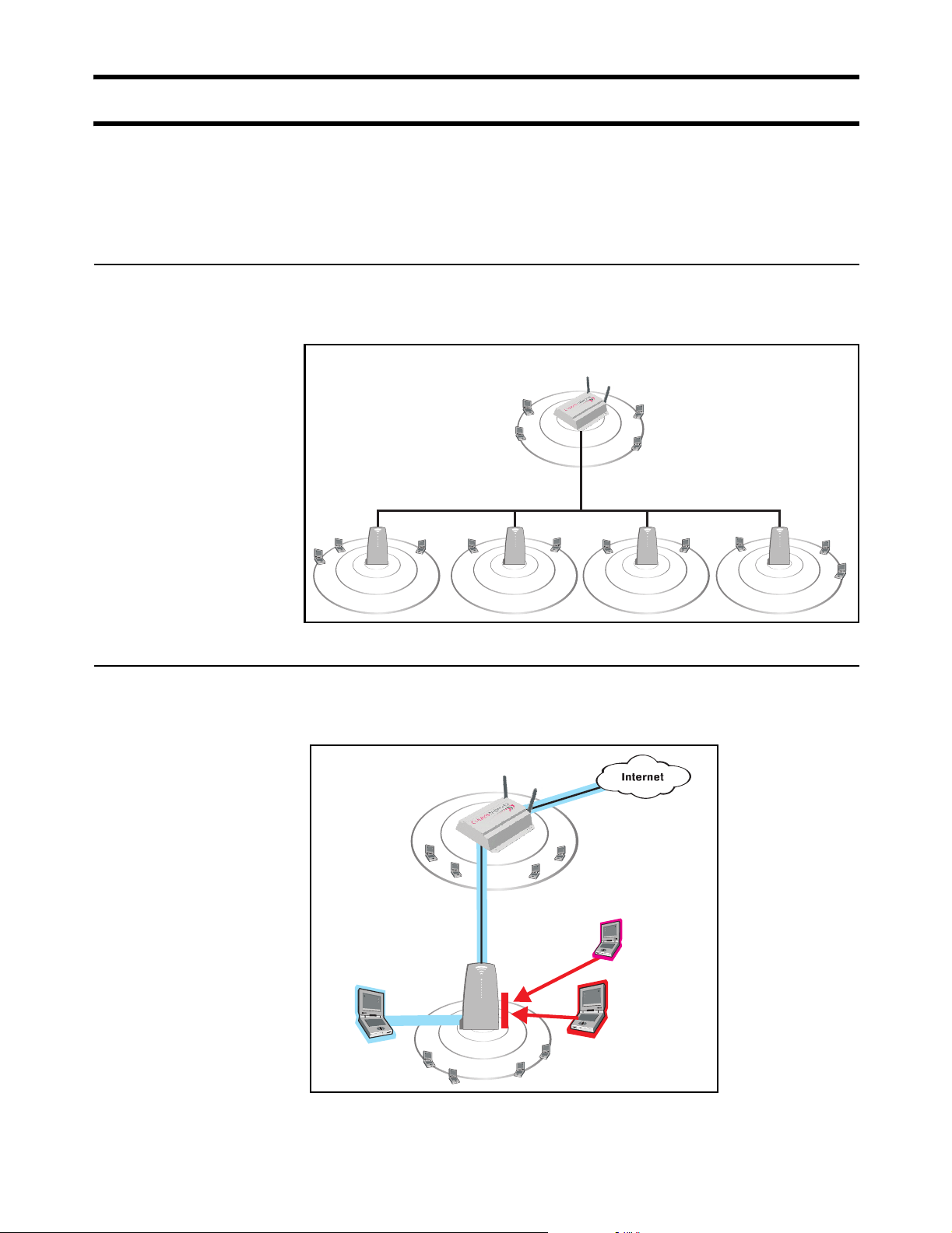
Scalable solution
Secure
infrastructure
To service large locations or areas with many customers, you can deploy multiple
CN3200s or use CN300 satellite stations to extend the reach of the wireless
network.
CN3200
P
U
N
B
A
L
L
I
C
W
CN300CN300CN300 CN300
P
U
N
B
A
L
L
I
C
W
P
U
N
B
A
L
L
I
C
W
P
U
N
B
A
L
L
I
C
W
P
U
N
B
A
L
L
I
C
W
The CN3200 and the CN300s provide the wireless cells which customers use to
connect their mobile computers. Intelligent bridging software on the CN300s
restricts customer traffic so that it can only flow to and from the CN3200.
CN3200
P
U
B
L
N
A
L
I
C
W
Hacker
Authenticated
CN300
customer
Unauthenticated
customer
P
U
B
N
A
L
L
I
C
W
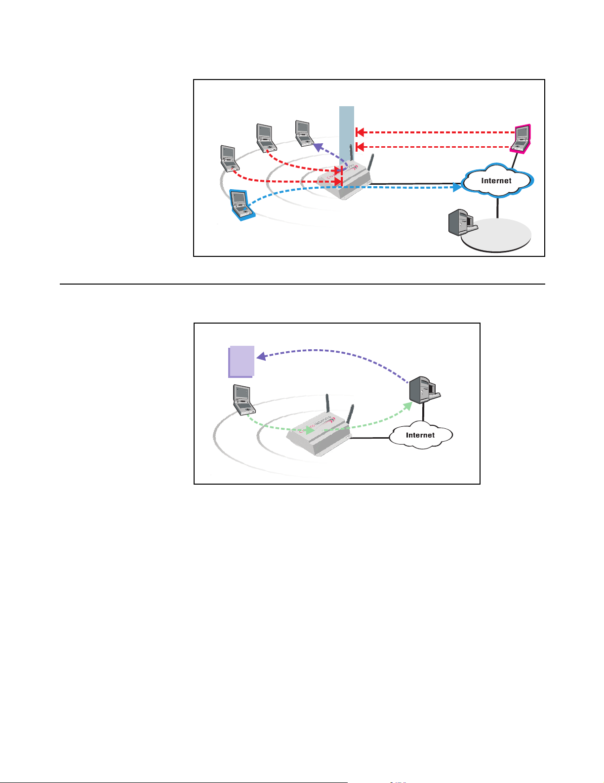
Generally, the CN3200 is configured to provide a ‘public’ area on the network that
is freely available to customers without logging in. However, to gain access to the
Internet (or restricted resources on the local network) customers are usually
required to login. This secures the network and enables billing to take place.
Page 9
Chapter 1: Introduction 9
DRAFT
For added security, the CN3200 is protected from malicious Internet traffic by its
integrated firewall.
Integrated
Stations cannot
exchange data
Unauthenticated
Customer
Authenticated
Customer
Firewall
telnet
syn attack
RADIUS
server
Hacker
Network
Operating Center
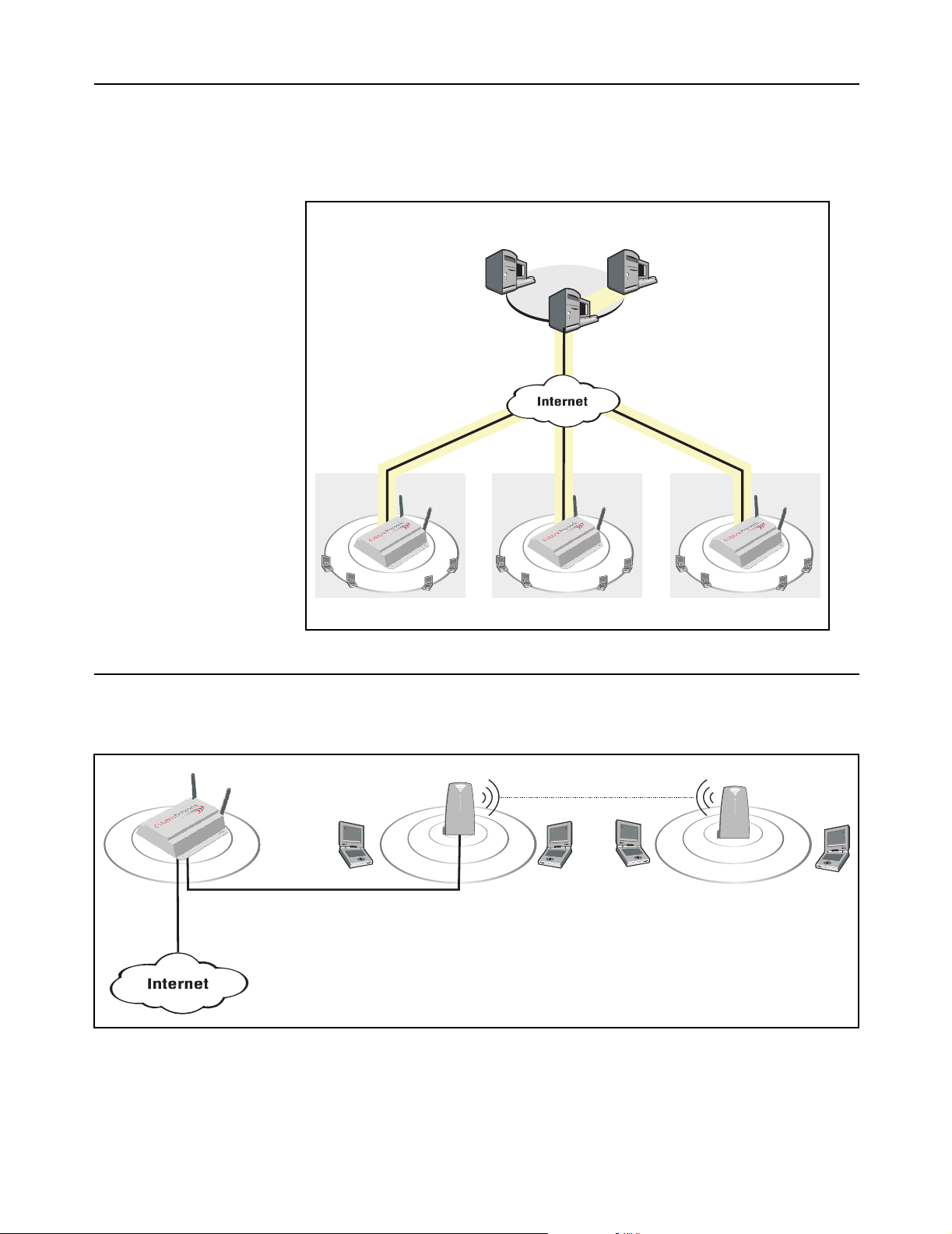
Enhanced user
experience
The CN3200 makes it easy to deliver a completely customized experience for
your customers.
Customized
Web Page
Customer location and login
name are forwarded to web server
Custom page
is built based
on Customer ID
and location
Web server
At login time, customers are authenticated and their location within the network is
identified. This information is forwarded to an external web server, enabling it to
generate a custom experience for each location or even every customer.
Page 10
Chapter 1: Introduction 10
DRAFT
Secure remote
management
Integrated VPN client software (PPTP and IPSec) enables the CN3200 to
establish a secure connection with a remote network operating center. This
provides a secure encrypted tunnel for management and accounting traffic,
enabling you to establish a centralized location from which to manage one or
more CN3200s.
Network
Operating
Center
Management
station
CN3200
RADIUS
server
VPN
server
Secure tunnels protected
by IPSec or PPTP.
CN3200 CN3200
Wireless bridging
CN3200
P
U
B
L
N
A
L
I
C
W
P
U
B
N
A
L
L
I
C
W
P
U
B
N
A
L
L
I
C
W
P
U
B
A
L
L
I
C
W
Site #1 Site #2 Site #3
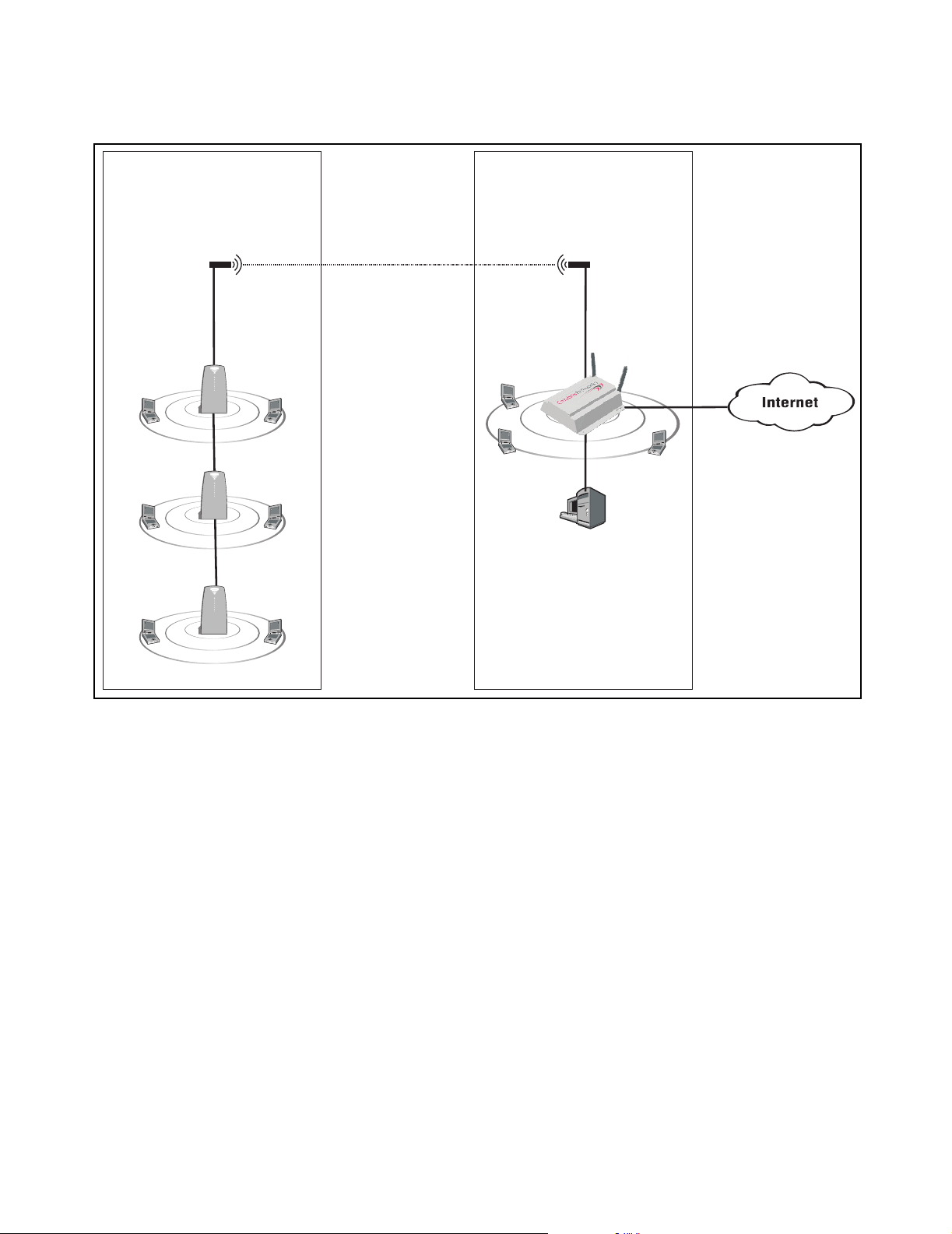
The CN3200s wireless bridging feature enables you to use the wireless radio to
create point-to-point wireless links to other access points. This feature can be
used locally to extend the reach of a network without laying cable. For example:
CN300
P
U
B
L
N
A
L
I
C
W
wireless bridge
CN300
P
U
B
L
N
A
L
I
C
W
Backbone LAN
N
Page 11
Chapter 1: Introduction 11
DRAFT
Or, it can be used to create point-to-point links over longer distances, such as
between two buildings (as illustrated below). This requires that the appropriate
external antenna be installed on each unit (not included).
Building A Building B
antenna antenna
wireless bridge
CN3200
CN300
P
U
B
N
A
L
L
I
C
W
P
U
B
L
I
C
W
CN300
RADIUS
P
U
B
N
A
L
L
I
C
W
server
CN300
P
U
B
N
A
L
L
I
C
W
N
A
L
Page 12
Chapter 1: Introduction 12
DRAFT
Multiple SSID
support
The CN3200 provides support for multiple SSIDs. This permits the wireless
network to be split into multiple distinct entities, each with its own SSID and
configuration settings.
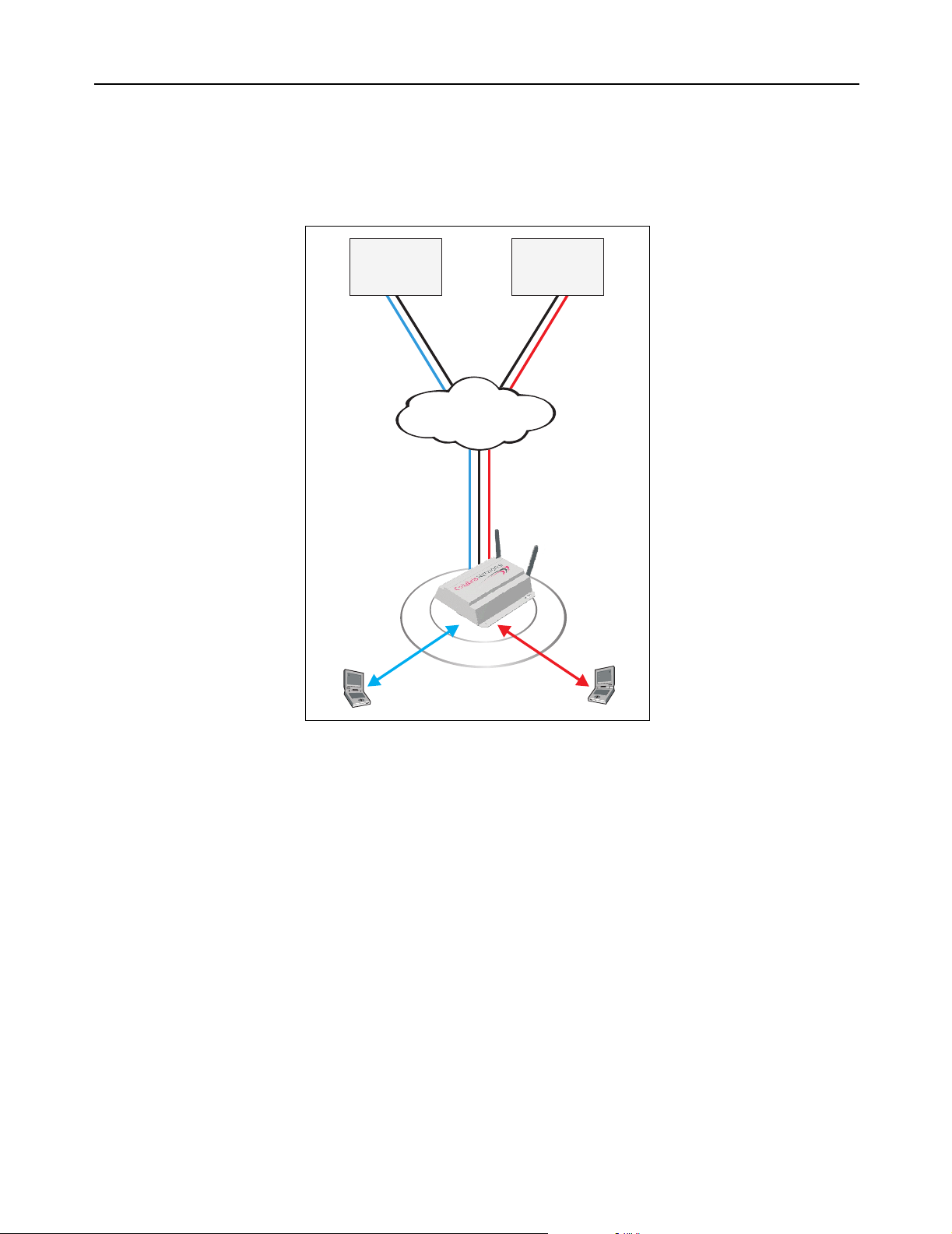
By combining multiple SSIDs and IPSec VPNs, several WISPs (wireless Internet
service providers) can effectively share wireless access points in one or more
locations.
WISP #1
NOC
IPSec VPN #1
WISP #2
NOC
IPSec VPN #2
Internet
IPSec VPN #1
IPSec VPN #2
P
SSID #1
U
B
L
N
A
L
I
C
W
SSID #2
In this scenario, the CN3200 controls access to the Internet. However, it validates
customer logins and records accounting information using the RADIUS server in
each NOC. The CN3200 knows which RADIUS server to communicate with for a
particular customer based on the SSID the customer is associated with. IPSec
VPN tunnels provide full protection for all data transfers with the NOC.
Custom login pages can be hosted by each WISP, enabling the shared access
point to provide a distinct online experience for each WISP’s customers.
Page 13

Chapter 1: Introduction 13
DRAFT
Feature summary
Wireless radio
The CN3200’s dual-band mini-PCI radio module is software configurable to
operate either in the 2.4GHz band (802.11b and 802.11g) or the 5GHz band
(802.11a).
Note: Customers are responsible for verifying approval and to identify the
regulatory domain that corresponds to a particular country. Not all regulatory
domains have been approved. Please consult the Colubris Networks web site
(www.colubris.com/certifications) for an up-to-date list.
802.11a
The following features apply when the radio is operating as IEEE 802.11a (5 Ghz
Unlicensed ISM radio band).
Data rates
• 6, 9, 12, 18, 24, 36, 48, 54 Mbps
Frequency band
• North America: 5.150-5.350 GHz and 5.725 -5.825 GHz
• Europe: 5.150-5.350 GHz and 5.470-5.725 GHz and 5.725-5.825 GHz
• Japan: 5.150-5.250 GHz
Operating channels (non-overlapping)
• North America: 12
• Europe: 19
• Japan: 4
Modulation technique
Orthogonal Frequency Division Multiplexing (OFDM)
• BPSK @ 6 and 9 Mbps
• QPSK @ 12 and 18 Mbps
• 16-QAM @ 24 and 36 Mbps
• 64-QAM @ 48 and 54 Mbps
Media Access Protocol
• Carrier Sense Multiple Access with Collision Avoidance (CSMA/CA)
Receive sensitivity
• 6 Mbps: -85 dBm
• 54 Mbps: -65 dBm
Available Transmit Power Settings
• 6-24 Mbps: 17.5dBm +/- 2
• 54 Mbps: 12 dBm +/- 2
Note: Maximum power setting varies according to individual country regulations.
Standards compliance
Safety
• IEC 60950
• EN 60950
Page 14

Chapter 1: Introduction 14
Radio Approvals
•Wi-Fi
• FCC Part 15.401-15.407
• RSS-210 (Canada)
• EN 300 440 (Europe)
• ARIB STD-T71 (Japan)
EMI and Susceptibility (Class B)
• FCC Part 15.107 and 15.109
• ICES-003 (Canada)
• VCCI (Japan)
• EN 301.489-1 and -17 (Europe)
Other
• IEEE 802.11a
• FCC Bulletin OET-65C
• RSS-102
DRAFT
IEEE 802.11h Support
• Dynamic Frequency Selection (DFS) and Transmit Power Control (TPC) are
supported as per the current draft of the IEEE 802.11h specification
Antenna
Two SMA (Female) connectors for use with external antenna (sold separately).
Security architecture client authentication
• SSL protected WEB-based Authentication
• 802.1X support including: PEAP, EAP-TLS, EAP-TTLS, and EAP-SIM to yield
mutual authentication
• Wi-Fi Protected Access (WPA) with AES support in HW (ready for WPA-2)·
Support for static and dynamic IEEE 802.11 WEP keys of 40 bits and 128 bits
802.11b/g
The following features apply when the radio is operating as IEEE 802.11b and
802.11g (2.4 Ghz Unlicensed ISM radio band).
Data rates
• IEEE 802.11b: 1, 2, 5.5, and 11 Mbps
• IEEE 802.11g (OFDM only): 6, 9, 12, 18, 24, 36, 48, 54Mbps
Frequency band
• North America: 2.412 to 2.462 GHz
• Europe: 2.412 to 2.472 GHz
• Japan: 2.412 to 2.484 GHz
Operating channels
• North America/China: 1
• Europe: 13
• Japan: 14
Non-overlapping operating channels
• Worldwide: 3
Page 15

Chapter 1: Introduction 15
DRAFT
Modulation technique
IEEE 802.11b: Direct sequence spread spectrum (DSSS)
• DBPSK @ 1 Mbps
• DQPSK @ 2 Mbps
• CCK @ 5.5 and 11 Mbps
IEEE 802.11g: Orthogonal Frequency Division Multiplexing (OFDM)
• BPSK @ 6 and 9 Mbps
• QPSK @ 12 and 18 Mbps
• 16-QAM @ 24 and 36 Mbps
• 64-QAM @ 48 and 54 Mbps
Media Access Protocol
• Carrier Sense Multiple Access with Collision Avoidance (CSMA/CA)
Receive sensitivity
IEEE 802.11b
• 11 Mbps: -86 dBm
IEEE 802.11g:
• 6 Mbps: -85 dBm
• 54 Mbps: -65 dBm
Available Transmit Power Settings
IEEE 802.11b
• 1-11 Mbps: 18 dBm +/- 2
IEEE 802.11g:
• 6-24 Mbps: 17 dBm +/- 2
• 54 Mbps: 11.5 dBm +/- 2
Note: Maximum power setting varies according to individual country regulations.
Standards compliance
Safety
• IEC 60950
• EN 60950
Radio Approvals
•Wi-Fi
• FCC Part 15.247
• RSS-139-1, RSS-210 (Canada)
• EN 300.328 (Europe)
• TELEC 33B (Japan)
EMI and Susceptibility (Class B)
• FCC Part 15.107 and 15.109
• ICES-003 (Canada)
• VCCI (Japan)
• EN 301.489-1 and -17 (Europe)
Other
• IEEE 802.11a
• FCC Bulletin OET-65C
• RSS-102
Page 16

Chapter 1: Introduction 16
DRAFT
Antenna
Two SMA (Female) connectors for use with external antenna (sold separately).
Security architecture client authentication
• SSL protected WEB-based Authentication
• 802.1x support including: PEAP, EAP-TLS, EAP-TTLS, and EAP-SIM to yield
mutual authentication
• Wi-Fi Protected Access (WPA) with AES support in HW (ready for WPA-2)·
Support for static and dynamic IEEE 802.11 WEP keys of 40 bits and 128 bits
Hardware
Status LEDs
Provide status of wireless port, LAN ports, and power
Uplink ports
Two auto-sensing 802.3 10/100BASE-T Ethernet ports
Memory
• 32 Mbytes RAM
• 16 Mbytes FLASH
Input power requirements
• 90 to 240 VAC +/- 10% (power supply)
• IEEE 802.3af 48 VDC +/- 10%(device)
Power draw
8 watts
Dimensions
• Length: 165.7 mm
• Width: 162.5 mm
• Height: 48 mm
Temperature range
• Operating: 0°C to 60°C
• Storage: -40°C to 70°C
Networking
Humidity
5% to 95% typical (non-condensing)
Warranty
One year
• IEEE 802.1d compliant bridging
• GRE (RFC 2784)
• DHCP Server (RFC 2131)
• DHCP Client
• DHCP Relay
• DHCP Option 82 (RFC 3046)
• PPPoE Client (RFC 2516)
• DNS Relay
• Static IP Routing
• Network Address Translation (RFC 1631)
• One-to-one NAT for VPN support
Page 17

Chapter 1: Introduction 17
• RIP v1 (RFC 1058) and v2 (RFC 1723)
• SMTP (e-mail) redirection
• ICMP (RFC 792)
• ARP (RFC 826)
• CIDR (RFC 1519)
DRAFT
Network
management
Access controller
functions
• SNMP v1 and v2
• MIB-II with TRAPS
• Colubris Hot Spot MIB for user session control and downstream AP
management
• RADIUS Authentication MIB (RFC 2618)
• RIP v2 extension MIB (RFC 1724)
• Secure access (SSL and VPN) to embedded HTML Management Tool
• Scheduled configuration and firmware upgrades from central server
• Real-time status, information and protocol traces (layer 2 and 3)
• Secure HTML login page
• Support for centralized WEB Portal
• WEB-Proxy server
• Fixed-IP address spoofing
• Location-aware user authentication
• Support for 802.1x using EAP-SIM, EAP-TLS, EAP-TTLS and PEAP
• MAC-level authentication for non-HTTP or 802.1x devices
• RADIUS AAA using EAP-MD5, PAP, CHAP, MSCHAP v2
• Provides detailed accounting based on session duration and/or volume of data
• Flexible support for pre-paid subscription
• Support up to 100 concurrent users at location
Security
RF Tools
Compatibility
• RADIUS Client (RFC 2865 and 2866)
• Layer-2 Wireless Isolation
• Integrated VPN client (IPSec or PPTP) for secure connection to central
RADIUS Server
• Per-user customizable firewall
• Rogue AP detection
• Embedded Site Survey tools
• Communicates with all Wi-Fi certified wireless adapters
• Supports all operating systems
Page 18

Chapter 1: Introduction 18
DRAFT
Authentication and
accounting
Management
• Secure HTML login page
• Support for 802.1x using EAP-MD5, EAP-TLS, EAP-TTLS, PEAP
• RADIUS AAA supporting EAP-MD5, PAP, CHAP, MSCHAP v2, MSCHAP v1
• MAC-level authentication for non-HTTP devices
• Supports up to 100 concurrent users
• Provides accounting by time used or data transferred/received by customers
• Traffic quotas
• Web-based management tool
• Secure local and remote management via HTTPS and VPN
• Scheduled configuration upgrades from a central server
• Remote Syslog
• Web-based firmware upgrades
• Real-time status and information protocol traces
• Site survey and monitoring tool
• SNMP V1, V2 MIB-II with traps and Colubris MIB
• RADIUS Authentication Client MIB (RFC 2618)
Interfaces
Operating
Environment
Regulatory
Approvals
• IEEE 802.11b wireless port
• 10/100BaseTX Ethernet port
• 10BaseT Ethernet port
• Temperature: 0ºC to 55ºC
• Humidity: 15% to 95% non-condensing
• FCC Part 15, CSA NRTL (C22.2 No 950, UL 1950)
• CE Mark (EN55022, EN55024, IEC 60950)
• Wi-Fi Certified
Page 19
Chapter 1: Introduction 19
DRAFT
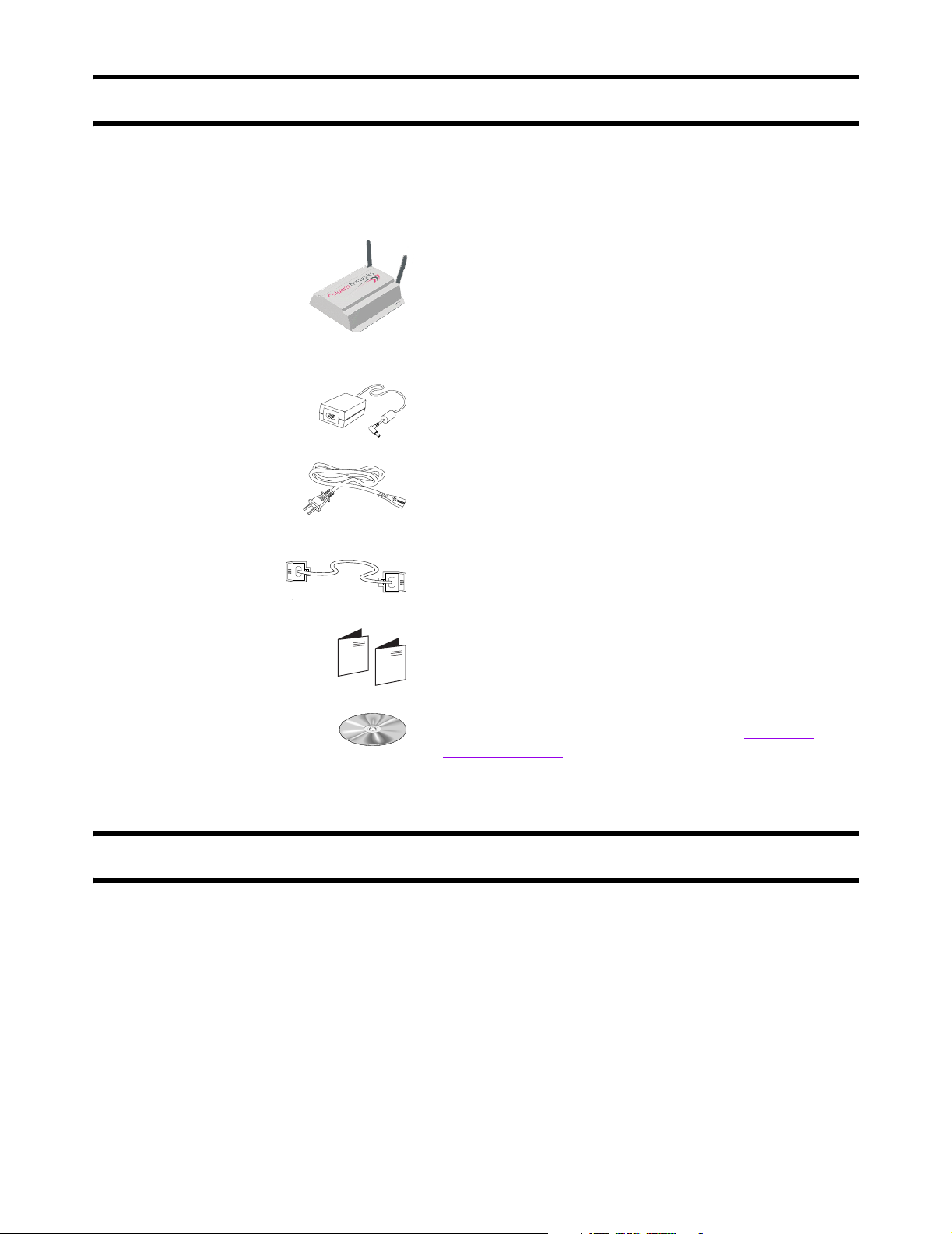
Package contents
Make sure that your package contains the following items. If an item is missing,
contact your reseller.
CN3200 Wireless Access Controller
Power supply (optional)
Power cord (optional)
Technical support
Cross-over Ethernet cable (yellow)
CN3200 warranty, license, and registration cards
CD-ROM
Contains the CN3200 Administrator’s Guide, Colubris
Backend Archive, and the Colubris Enterprise MIB.
To obtain technical support, contact your reseller.
Information about Colubris Networks products and services, including
documentation and software updates, is available on our web site at
www.colubris.com.
Page 20

Chapter 1: Introduction 20
DRAFT
Syntax conventions
This manual uses the following formatting conventions.
Example Description
Network When referring to the management tool
web interface, items in bold type identify
menu commands or input fields. They are
presented exactly as they appear on
screen.
Network > Ports When referring to the management tool
web interface, submenus are indicated
using the ‘>’ sign. The example refers to
the Ports submenu, which is found under
the Network menu.
ip_address
use-access-list=usename
ssl-certificate=URL [%s] [%n]
Items in italics are parameters that you
must supply a value for.
Monospaced text is used to present
command line output, program listings, or
commands that are entered into
configuration files or profiles.
Items enclosed in square brackets are
optional. You can either include them or
not. Do not type the brackets.
Page 21

Chapter 2: Important concepts 21
Chapter 2: Important concepts
DRAFT
Chapter 2
Important concepts
This chapter covers important topics that will help to understand how
to install, deploy, and manage a wireless public access network.
Page 22
Chapter 2: Important concepts 22
DRAFT
Networking areas
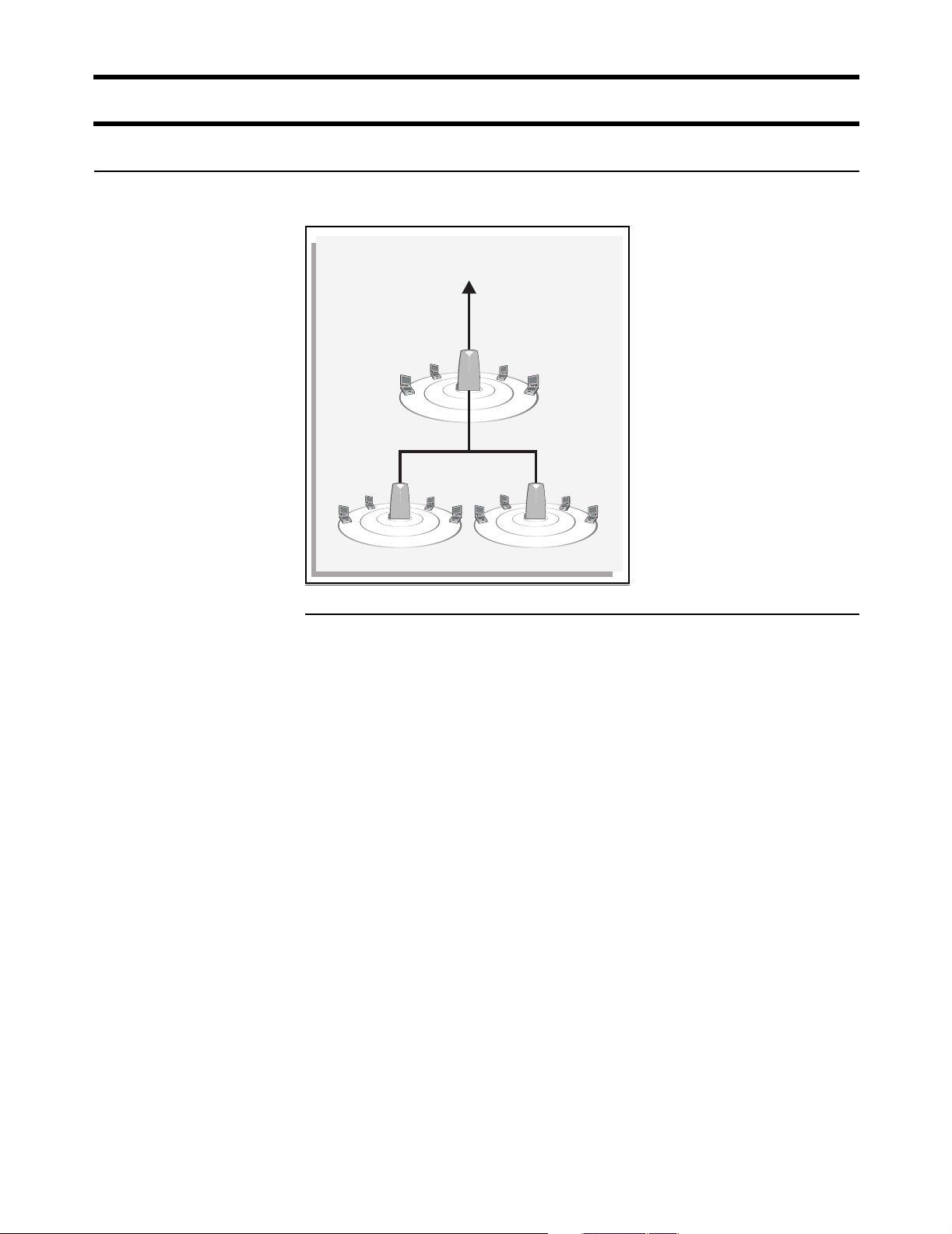
Wireless cells
Each wireless networking area is created by installing a CN3200, and if needed,
one or more CN300s. For example:
Protected network resources
P
U
B
N
A
L
L
I
C
W
CN300CN300
P
U
N
B
A
L
L
I
C
W
P
U
N
B
A
L
L
I
C
W
Coverage
As a starting point for planning your setup, you can assume that the CN3200
provides a wireless cell of up to 300 feet (100 meters) in diameter at high power.
Before creating a permanent installation, you should always perform a live test of
the coverage provided by each access point to determine its optimum settings
and location.
Coverage provided by an access point will be affected by all of the following
factors.
Transmission power of the radio
More power means better signal quality and bigger wireless cells. However, cell
size should generally not exceed the range of transmission supported by your
client stations. If it does, client stations will be able to receive signals from the
access point, but they will not be able to reply. Another limiting factor is proximity
of other access points in a multi-cell setup. In this case signal strength should be
adjusted to avoid interference between adjacent cells.
Note: Governmental regulations in different parts of the world determine the
maximum power output of the CN3200’s radio.
Antenna configuration
Antennas play a large roll in determining shape of the wireless cell and
transmission distance. Internal antennas are general omni-directional and
provide the same type of coverage in all directions around the access point.
Consult the specifications for the antenna to determine how it affects wireless
coverage.
Interference
Another limiting factor is interference from other access points or devices that
operate in the same frequency band.
Page 23

Chapter 2: Important concepts 23
Access points operating in the 2.4 Ghz band may experience interference from
2.4 Ghz cordless phones and microwave ovens.
DRAFT
Physical characteristics of the location
To maximize coverage of the wireless cell, the wireless access points are best
installed in an open area with as few obstructions as possible. Try to choose a
location that is central to the area being served.
Radio waves cannot penetrate metal, instead they are reflected. This means that
the wireless access points are able to transmit through wood or plaster walls, and
closed windows. However, the steel reinforcing found in concrete walls and floors
may block transmissions, or reduce signal quality by creating reflections. This
can make it difficult for a single unit to serve users on different floors in a concrete
building. Such installations will require a separate wireless access points on each
floor.
Authentication and accounting
The CN3200 provides user authentication and accounting support for the
wireless customers and manages the security of the network. This means
ensuring that only authorized traffic is permitted to reach the protected network
resources.
Multiple SSIDs
The CN3200 supports the creation of multiple virtual wireless networks, all
sharing the same wireless port. Each virtual network has its own SSID, MAC
address, and configuration settings.
Security
To preserve network security, the CN3200 and the CN300 block all
communications between wireless client stations. If required, you can disable this
feature.
Protected network resources
All resources connected to the CN3200’s Internet port are protected. This means
that access to them is controlled by configuration settings on the CN3200. By
default, these settings are:
• unauthenticated customers cannot access any protected network resources
• authenticated customers can access all protected network resources
While this type of configuration may be suitable for a simple wireless hotspot that
provides access to the Internet, more complex setups will need more fine-grained
control of the protected network resources. To support this, the CN3200 provides
a fully-configurable access list mechanism, which has the following benefits:
• The ability to make specific protected resources available to unauthenticated
users. For example, when you want to have public web pages available to
customers before they log in, but locate the web server on a protected network.
• The ability to define a list of accessible resources for a single customer or a an
entire group. For example, if you have several customer groups (teachers,
students, visitors), each can be given access to specific network resources.
• The ability to block specific addresses for a single customer or entire group. For
example, you could disallow traffic to file swapping Internet sites to cut down on
bandwidth usage.
Page 24

Chapter 2: Important concepts 24
DRAFT
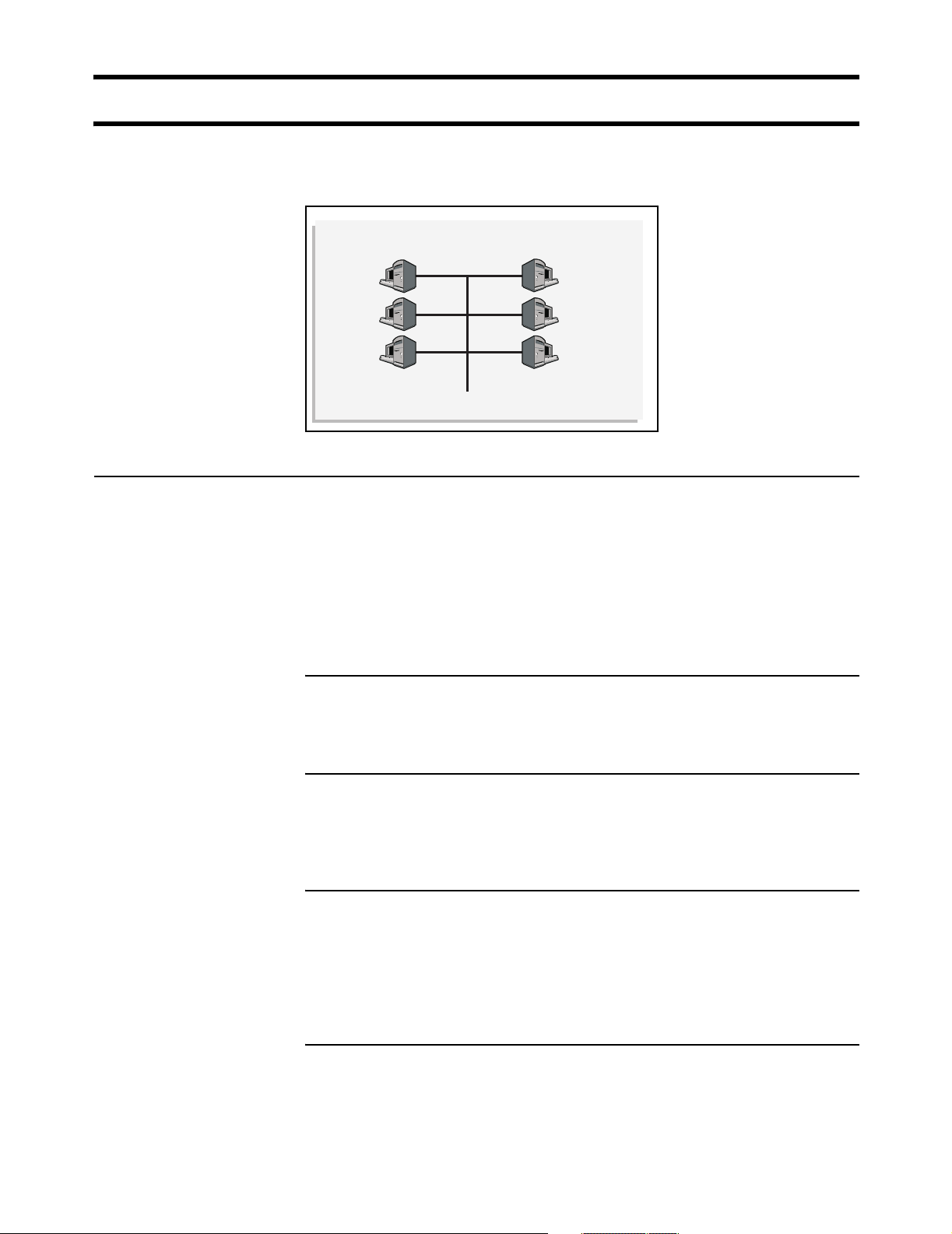
Attaching to a wired
LAN
The CN3200 can be attached to a wired LAN. Computers on an attached wired
LAN are treated just like those on the wireless LAN. Each computer must be
authenticated before it can gain access to protected network resources.
To maintain network security, the wireless LAN and wired LAN are distinct. Traffic
is not forwarded between them.
Page 25
Chapter 2: Important concepts 25
DRAFT
Network operating center (NOC)
The NOC is where the RADIUS, Web, SMTP, FTP, DHCP, DNS, VPN servers and
the management station are installed.
Network Operating Center
NOC components
SMTP
server
Web/FTP
server
RADIUS
server
DNS/DHCP
server
Management
station
VPN
server
RADIUS server
The RADIUS server is used to authenticate customers when they log onto the
network and record accounting information for each session. It is also used to
store configuration settings for the CN3200 and customers. Before the CN3200
activates the public network, it must authenticate itself to the RADIUS server and
retrieve its configuration information.
The CN3200 is compliant with RFC 2865 and RFC 2866 and will work with a
variety of RADIUS servers.
Web/FTP server
If you intend to customize the look and feel of the public access interface, you will
need a Web or FTP server to store your customized pages.
SMTP server
The CN3200 provides an e-mail redirection feature which enables customers to
send e-mail using a SMTP server that you supply. If you intend to support this
feature, you must install an SMTP server to handle redirected outgoing mail.
VPN server
The CN3200 can use its integrated VPN client (PPTP, IPSec) to create an
encrypted connection to a VPN server. This is useful if the CN3200 is connected
to a NOC via the Internet. The tunnel ensures the security of authentication traffic
and remote management activities and enables you to manage all your CN3200s
from a single remote site without security concerns.
DNS/DHCP server
The CN3200 can be configured to relay DHCP requests to an external server.
This enables you to control address allocation for all wireless cells from a central
location.
Page 26

Chapter 2: Important concepts 26
DRAFT
Management station
This station is used to control and configure the CN3200 and any satellite
CN300s. Control can occur via an SNMP console or through the CN3200’s webbased management tool.
Sending traffic to
the NOC
For secure transmission of traffic between the CN3200 and the NOC, the
CN3200 features both PPTP and IPSec clients. Chapter 10 explains how to
configure secure remote connections.
Page 27

Chapter 2: Important concepts 27
DRAFT
The public access interface
The public access interface is the sequence of web pages that customers use to
login to the wireless network and to manage their accounts.
The CN3200 ships with a default public access interface that you can customize
to meet the needs of your installation. However, before you do this, you should
initialize the default setup and test it with your network as described in Chapter 9.
Once the default interface is working, you can make changes to it as described in
Chapter 15.
Important: The CN3200 public access interface is not functional until the
CN3200 can successfully connect to a RADIUS server and authenticate itself.
This means that the login page for the public access interface will appear, but
customers will get an error when they try to log in. This occurs regardless of the
method you are using to authenticate customers.
Important: Customers using PDAs that only support a single browser window
will have difficulty using the public access interface in its standard configuration.
To solve this problem, see “Supporting PDAs” on page 172.
Page 28

Chapter 2: Important concepts 28
DRAFT
Connecting to and using the wireless network
In order to access protected network resources, customers must:
• successfully connect to the wireless network
• open the login page in their web browser and supply a valid username and
password OR login with an 802.1x or WPA client (if this feature is enabled on
the CN3200)
The CN3200 provides several features that make it easy for customers to
accomplish these tasks.
Broadcast IP
address
Allow any IP
address
WPA/802.1x clients
This feature enables the CN3200 to broadcast its wireless network name (SSID)
to all client stations. Most wireless adapter cards have a setting that enables
them to automatically discover access points that broadcast their names and
automatically connect to the one with the strongest signal.
This feature is enabled by default. To disable it go to the Network > Wireless
page in the CN3200 management tool. If you disable this feature, customers
must manually specify the SSID you define for the wireless network.
This feature enables the CN3200 to connect with wireless client stations that are
using a static IP address that is not on the same segment as the wireless
network. This permits customers to access the wireless network without
reconfiguring their network settings.
For example, by default the CN3200 assigns creates the wireless network on the
subnet 192.168.1.0. If a client station is pre-configured with the address
10.10.4.99, it will still be able to connect to the CN3200 without changing its
address, or settings for DNS server and default gateway.
This feature is enabled by default. To disable it go to the Security >
Authentication > Advanced Settings page in the CN3200 management tool.
The CN3200 provides complete support for these clients. User accounts are
managed remotely on a RADIUS server.
Proxy server
support
This feature enables the CN3200 to support client stations that are configured to
use a proxy server for HTTP and HTTPS, without requiring customers to
reconfigure their systems.
This feature is disabled by default. To enable it, go to the Client station settings
box on the Security > Authentication > Advanced Settings page.
For this feature to work, client stations:
• must not be using a proxy server on port 21, 23, 25, 110, 443, 8080, or 8090.
To support ports 8080 and 8090 change the settings for Security >
Authentication > Advanced Settings > Access controller ports.
• must be using the same proxy server address and port number for both HTTP
and HTTPS.
• must not be using 802.1x.
Enabling this feature reduces the maximum number of supported wireless
customers to 50.
Page 29

Chapter 2: Important concepts 29
DRAFT
The RADIUS server
Main tasks
The RADIUS server is a key component of the public access infrastructure. It is
used to perform a variety of tasks, including:
• authenticating the CN3200
• authenticating administrator logins
• authenticating customer logins
• storing accounting information for each customer
• storing customization information for the public access interface
Authenticating the CN3200 and storing config information
The CN3200 authenticates itself to a RADIUS server each time:
• it is powered up
• it is restarted
• the authentication interval expires (configured via the management tool)
At each authentication, the following configuration information is retrieved if
defined in the RADIUS profile for the CN3200:
• Access list defining the resources unauthenticated customers can access.
• URLs specifying the location of customized Web pages and supporting files.
• A URL specifying the location of a custom security certificate.
• A URL specifying the location of a configuration file.
• The MAC addresses of devices to authenticate.
• The default idle timeout for customer sessions.
• The default address for the SMTP redirection
When you set up a profile for the CN3200 on the RADIUS server you define this
information in the form of a Colubris Networks vendor-specific attribute. For
details see page 214.
More information
Authenticating customers and storing accounting information
See page 30 for details.
Authenticating administrator logins
The RADIUS server can also be used to authenticate administrator logins. This
enables you to have multiple administrators, each with their own username and
password, instead of the single account controlled on the Management >
Management tool page.
For information on configuring the RADIUS server, see:
• Chapter 16, which explains all the settings you can define on the RADIUS
server for your customer accounts and network operation.
• Chapter 18, which provides a walkthrough of a sample RADIUS configuration
using Steel-belted Radius.
• Chapter 19, which provides a walkthrough of a sample RADIUS configuration
using Microsoft's RADIUS server: Internet Authentication Service.
Page 30

Chapter 2: Important concepts 30
DRAFT
Customer authentication
This manual uses the term customer to refer to any person or device that logs
into the public access network created by the CN3200.
Customers can be authenticated in several ways.
RADIUS server
Local user list
This method enables you to use the services of a RADIUS server to manage
your customers, track and manage connection time, and generate billing
information.
Once the customer is authenticated, configuration information is retrieved for the
customer. This includes settings for:
• Connection time limit for the customer’s session.
• Idle time limit for the customer’s session.
• Access list for the customer.
• Address of the e-mail server to use for redirection of the customer’s e-mail.
• URLs specifying the location of customized Welcome and Goodbye pages for
the customer.
When you define a profile for each customer on the RADIUS server you define
this information in the form of regular RADIUS attributes and a Colubris Network
vendor-specific attribute. See “Creating customer profiles on the RADIUS server”
on page 225 for more information.
The CN3200 enables you to create local accounts that bypass RADIUS
authentication and accounting. To login, customers use the public access
interface, but instead of using the RADIUS server, authentication is handled
directly by the CN3200 and no RADIUS accounting information is logged. These
accounts are useful for system administrators and management personnel.
Note: Local users can must use HTML to login. WPA/802.1x users must be
authenticated via RADIUS.
MAC-based
authentication
WPA/802.1x
To setup these accounts, login to the management tool and open the Security >
User List page.
The CN3200 can authenticate devices based on their MAC address. This is
useful for authenticating devices that do not have a web browser (cash registers,
for example). These devices do not log in through the public access interface,
rather, as soon as the CN3200 sees their MAC address appear on the network,
the CN3200 attempts to authenticate them. To setup these accounts, see page
223.
The CN3200 provides full support for users with 802.1x or WPA client software.
The CN3200 terminates the session and authenticates users via an external
RADIUS server or by using preshared keys (WPA only).
The CN3200 supports 802.1x client software that uses EAP-TLS, EAP-TTLS,
and PEAP. Dynamic key rotation is supported.
Page 31

Chapter 3: Planning your installation 31
Chapter 3: Planning your installation
DRAFT
Chapter 3
Planning your installation
This chapter provides sample deployment strategies for two common
scenarios. These scenarios will give you a good idea on how to approach
your installation.
Page 32

Chapter 3: Planning your installation 32
DRAFT
Multi-site installation
Network Operating Center
SMTP
server
Web/FTP
server
RADIUS
server
DNS/DHCP
server
Management
station
VPN
server
Router/Firewall
Site #1 Site #2 Site #3
CN3200
P
U
N
B
A
L
L
I
C
W
CN300 CN300CN300 CN300
CN3200
P
U
N
B
A
L
L
I
C
W
CN3200
P
U
N
B
A
L
L
I
C
W
P
U
N
B
A
L
L
I
C
W
About this
installation
P
U
N
B
A
L
L
I
C
W
P
U
N
B
A
L
L
I
C
W
P
U
N
B
A
L
L
I
C
W
• A single CN3200 is installed along with one or more CN300 satellites at sites
#1 and #3.
• At site #2, the CN3200 provides a wireless network and is also connected to a
LAN to enable a number of wired computers to act as public access stations.
• Each CN3200 is connected to the Internet via a broadband modem. The
Internet connection is protected by the CN3200’s firewall.
• A VPN connection is established between each CN3200 and the VPN server at
the NOC. This protects all management traffic exchanged between the
CN3200s and the NOC, which includes:
• RADIUS authentication and accounting data.
• Management session used to control CN3200 configuration and firmware
updates.
• Centralized management of customer profiles on the RADIUS server enables
customers to login at any location.
Page 33

Chapter 3: Planning your installation 33
DRAFT
Installation strategy
General configuration tasks
Step Description See
1 Setup and configure profiles on the RADIUS server(s). Pages 213 to 232
2 Create custom web pages for the public access
interface. (optional)
3 Create custom certificates. (optional) Chapter 14
Chapter 15
Site #1 and #3
Step Description See
1 Setup the CN3200. Chapter 4
2 Establish a connection to the management tool. Pages 44 and 46
3 Define management tool security settings. Page 49
4 Configure and deploy the multi-cell wireless network
with the CN300s.
5 Configure the Internet connection and firewall. Chapter 8
6 Start the public access interface. Chapter 9
Chapter 6
7 Configure a VPN connection to the NOC. Chapter 10
Site #2
Step Description See
1 Setup the CN3200. Chapter 4
2 Establish a connection to the management tool. Pages 44 and 46
3 Define management tool security settings. Page 49
4 Configure the wireless network. Chapter 6
5 Connect the CN3200 to the local wired LAN. Chapter 7
6 Configure the Internet connection and firewall. Chapter 8
7 Start the public access interface. Chapter 9
8 Configure a VPN connection to the NOC. Chapter 10
Page 34

Chapter 3: Planning your installation 34
DRAFT
Multi-area installation
Network Operating Center
CN1500
SMTP
server
Web/FTP
server
RADIUS
server
Backbone LAN
Area #1 Area #2 Area #3
CN3200
CN3200
HDDPWR
12345678
GPIO
Reset
Management
station
modem
CN3200
P
U
P
U
N
B
A
L
L
I
C
W
About this
installation
P
N
B
A
L
L
I
C
W
U
N
B
A
L
L
I
C
W
CN300CN300
P
U
N
B
A
L
L
I
C
W
P
U
N
B
A
L
L
I
C
W
CN300CN300
P
U
N
B
A
L
L
I
C
W
P
U
N
B
A
L
L
I
C
W
• A single CN3200 is installed along with one or more CN300 satellites at areas
#1 and #3.
• At area #2, the CN3200 provides a wireless network and is also connected to a
LAN to enable a number of wired computers to act as public access stations.
• Each CN3200 is connected to the NOC via the backbone LAN.
• Centralized management of customer profiles on the RADIUS server enables
customers to login to the wireless network in any area.
Page 35

Chapter 3: Planning your installation 35
DRAFT
Installation strategy
General configuration tasks
Step Description See
1 Setup and configure profiles on the RADIUS server(s). Pages 213 to 232
2 Create custom web pages for the public access
interface. (optional)
3 Create and install a custom certificate (optional). Chapter 14
Chapter 15
Area #1 and #3
Step Description See
1 Install the CN3200. Chapter 4
2 Establish a connection to the management tool. Pages 44 and 46
3 Define management tool security settings. Page 49
4 Configure and deploy the multi-cell wireless network
with the CN300s.
5 Connect the Internet port to the backbone LAN and
configure IP addressing.
Chapter 6
Page 79
6 Start the public access interface. Chapter 9
Area #2
Step Description See
1 Install the CN3200. Chapter 4
2 Establish a connection to the management tool. Pages 44 and 46
3 Define management tool security settings. Page 49
4 Configure the wireless network. Chapter 6
5 Connect the CN3200 to the local wired LAN. Chapter 7
6 Connect the Internet port to the backbone LAN and
configure IP addressing.
7 Start the public access interface. Chapter 9
Page 79
Page 36

Chapter 3: Planning your installation 36
DRAFT
Page 37

Chapter 4: Installation 37
Chapter 4: Installation
DRAFT
Chapter 4
Installation
This chapter provides an overview of the CN3200 hardware and explains
how to install it.
Page 38

Chapter 4: Installation 38
DRAFT
Anatomy
Antenna Connectors
LAN port Internet port
Serial port
Antenna
connectors
Ports
Power
light
Power
connector
The CN3200 has two antenna connectors. Both can transmit and receive. If a
single antenna is used it can be attached to either connector.
The connectors are SMA male with reverse polarity. This means antennas or cable
connectors must be SMA female with reverse polarity. Antennas should be 2 dBi or less
and can be either directly attached or attached via a coax cable.
Ethernet
light
Wireless
light
Reset button
Antenna diversity
The CN3200 supports antenna diversity. One benefit of this feature is that for a
given client station connection, the CN3200 always transmits on the antenna it
receives.
If transmission fails, the CN3200 automatically switches antennas and retries.
The CN3200 has three ports:
LAN port
The CN3200 has two antenna connectors. Both can transmit and receive. If a
single antenna is used it can be attached to either connector. The connectors are
SMA male with reverse polarity. This means antennas or cable connectors must
be SMA female with reverse polarity. Antennas should be 2 dBi or less and can
be either directly attached or attached via a coax cable.
Serial port
For future use. Do not connect this port to telecommunications equipment or a phone line.
Internet port
10/100 mbps Ethernet port with RJ-45 connector. Do not connect this port directly to a
metropolitan area network (MAN) or wide area network (WAN).
Page 39

Chapter 4: Installation 39
DRAFT
Powering the
CN3200
Status lights
There are two ways to power the CN3200: DC adapter or PoE.
DC power adapter
The supplied DC power adaptor provides 2A at 5V.
Important: The power adapter is not rated for use in plenum installations.
Power over Ethernet (PoE)
The CN3200 supports PoE on the LAN port and can be used with any IEEE
802.3af-compliant power injector.
Important: Cisco PoE injectors are not compliant with IEEE 802.3af and cannot
be used with the CN3200.
The status lights provide the following operational information.
Power
on The CN3200 is fully operational.
flashing The CN3200 is starting up.
off Power is off.
Ethernet
on LED comes on for a short period when the link is established.
flashing Indicates that either port is transmitting or receiving.
off Ports are not connected or there is no activity.
Radio
Wireless
flashing Wireless port is receiving data.
Startup behavior
When power is applied to the CN3200, the power light will start flashing. When
the power light stops flashing, initialization is complete and the CN3200 is fully
operational.
The CN3200 provides support for IEEE 802.11a and 802.11b/g technologies in a
single radio which can be configured in real-time for complete flexibility of
operation.
• When operating in 802.11a mode, the radio supports data rates of up to 54
Mbps and eight non-overlapping channels.
• When operating in 802.11b/g mode, the radio provides data rates up to 54
Mbps and three non-overlapping channels to support both 802.11b and
802.11/g client stations.
Page 40

Chapter 4: Installation 40
DRAFT
Reset button
The reset button is located on the rear of the CN3200. Use the end of a paper
clip or another pointy object to press the button.
Restarting
Press and release the button quickly to restart the CN3200. This is equivalent to
disconnecting and reconnecting the power. The CN3200 will restart immediately.
Resetting to factory defaults
To reset the CN3200 to its factory default settings, do the following:
1. Press and hold the reset button. All the lights on the CN3200 front panel will
light up.
2. When the lights begin to flash (after about five seconds), immediately release
the button.
3. The CN3200 will restart with factory default settings. When the power light
stops flashing, the CN3200 is fully operational.
Important: Resetting the CN3200 deletes all your configuration settings, resets
the Administrator username and password to ‘admin’, and sets the Wireless port
IP address to 192.168.1.1 and the LAN port IP address 192.168.4.1.
The management tool can also be used to reset the CN3200 to its factory
defaults. See “Configuration management” on page 53 for details.
Page 41

Chapter 4: Installation 41
DRAFT
Installing the CN3200
Important: Installation must be performed by a professional installer familiar with
local regulations governing wireless devices.
Mounting the
CN3200
Configuring the
CN3200
When mounting the CN3200 on a wall, ceiling or other surface, make sure that:
• the surface you attach the CN3200 to and the fasteners you use are able to
support at least 5.1 kg (11.25 pounds)
• cable pull (accidental or otherwise), must not make the unit exceed the 5.1 kg
(11.25 pound) limit
Plenum installations
Plenum rated cables and attachment hardware must be used if the CN3200 is
installed in a plenum. Since the power adapter is not rated for plenum
installations, only the CN3200 and appropriate cabling can be located in the
plenum.
Note: If Colubris Networks supplied PoE injectors are used in a plenum
installation, they must be located outside the plenum.
Before attaching the CN3200 to your network, it is recommended that you start
the management tool and define basic configuration settings as described in
Chapter 5.
By default, the CN3200 is configured to operate as a DHCP server with a
network address of 192.168.1.1 on the wireless and 192.168.4.1 on the LAN
port.
The Internet port is configured to operate as a DCHP client.
Refer to Chapter 7 for complete instructions on how to attach the CN3200 to your
network.
Page 42

Chapter 4: Installation 42
DRAFT
Page 43

Chapter 5: The management tool 43
Chapter 5: The management tool
Chapter 5
The management tool
This chapter provides an overview of the Web-based management tool
and explains how to use it to perform management and configuration
tasks.
Page 44

Chapter 5: The management tool 44
Overview
The management tool is a Web-based interface to the CN3200 that provides
easy access to all configuration functions.
Important: Only one administrator can be logged into the management tool at a
given time. If a second administrator logs in while the first is connected, the first
administrator is logged out.
Management
station
The management station is the computer that you use to connect to the
management tool. To act as a management station, a computer must:
• have a JavaScript-enabled Web browser installed (Netscape 4.04 or higher, or
Internet Explorer 5.0 or higher).
• be able to establish an IP connection with the CN3200
Configuring the management station for wireless access
Install and configure the wireless adapter in the management station according
to the directions that came with it. During installation make sure that:
• encryption is disabled
• TCP/IP is installed and configured. IP addressing can be either static or DHCP.
A unique feature of the CN3500 is its ability to support connections from client
stations that have a preconfigured static IP address.
• Set the SSID to be “Colubris Networks”.
Configuring the management station for wired access
Install and configure a network adapter in the management station according to
the directions that came with it. During installation make sure that:
• TCP/IP is installed and configured. IP addressing can be either static or DHCP.
A unique feature of the CN3500 is its ability to support connections from client
stations that have a preconfigured static IP address.
Management
scenarios
Default settings
The CN3200 can be managed both locally and remotely for complete flexibility.
The following management scenarios are supported:
Local Management
Remote management
The following are some important default settings
Wireless port
• IP address: 192.168.1.1
• Wireless network name: Colubris Networks
• Operating frequency: Channel 10
• ESSID broadcast: On
Page 45

Chapter 5: The management tool 45
• Relay between wireless station: Off
• Security: None
LAN port
• IP address: 192.168.1.1
•
DHCP server: On
Internet port
• IP address: (DHCP client is active)
• Firewall: High security
Management tool
• Allow access via LAN port and port
• Login name: admin
• Password: admin
Page 46

Chapter 5: The management tool 46
Starting the management tool
1. Start your Web browser.
2. Press Enter. You will be prompted to accept a Colubris Networks security
certificate. Do so to continue. (To eliminate this warning message you can
install your own certificate as described in Chapter 14.)
To safeguard the security of the CN3200, access to the management tool
must occur via a secure connection. Before this connection can be
established, you must accept a Colubris Networks security certificate. The
procedure for accepting the certificate varies depending on the browser you
are using.
3. After you accept the Colubris Networks certificate, the management tool
home page opens.
By default, the username and password are both set to admin.
Page 47

Chapter 5: The management tool 47
Menu summary
The following is a brief overview of the management tool menu options. For
detailed information on each option and its parameters, consult the online
help, which is available by clicking the help icon that appears in the top right
corner of most boxes:
Home
Wireless
Network
Displays basic status information on the operation of the CN3200. For a
description of the information on the home page, see page 14.
Wireless overview
Provides a summary of important wireless settings.
Wi-Fi
Use this page to configure the operating characteristics of the wireless network.
WLAN profiles
Use this page to define multiple SSIDs.
Wireless links
Use this page to define point-to-point links to other access points.
Neighborhood
Use this page to do s site survey and discover other wireless access points that
are operating nearby.
Address allocation
Lets you configure the CN3200 to act as a DHCP server or DHCP relay agent,
and also to setup bandwidth management.
Security
IP routes
Lets you define routes to send traffic to the appropriate destination. This is useful
when the CN3200 is connected to a wired LAN which provides access to other
networks.
DNS
Enables you to override the default DNS servers assigned to the CN3200.
GRE
Lets you define GRE tunnels.
NAT
Lets you define static IP routes to make computers on the internal network
(WLAN or a connected wired LAN) visible to external computers. For example,
this can be used to run an FTP or Web server on the internal network.
RIP
Configures support for RIP.
The security menu lets you define all security-related settings.
Page 48

Chapter 5: The management tool 48
RADIUS
This is where you define the settings the CN3200 uses to communicate with
external RADIUS servers.
Firewall
Configures the settings for the built-in firewall that protects the Internet port.
PPTP client
Configures the settings for the PPTP client which enables the CN3200 to
establish a secure connection to a remote PPTP server via the Internet port.
IPSec
Configures the settings for the IPSec client which enables the CN3200 to
establish a secure connection to an IPSec peer via the Internet port.
Certificates
Use this option to manage the SSL certificates used by the CN3200.
Users
This is where you define user accounts when customer authentication is handled
directly by the CN3200, rather than using a RADIUS server.
Management
Status
Tools
The management menu enables you to configure the operation of the
management tool and its SNMP implementation.
Management tool
Use this page to set the admin name and password, and define security
parameters that control access to the management tool.
SNMP
Configures SNMP properties and security settings.
System time
Configures system time.
Lets you view the status of other active Colubris access points.
Use this option to view the status of the various components on the CN3200.
Provides diagnostic tools that can be used to investigate anomalies. Generally,
you will use these only under the direction of your reseller. These tools also
enable you to view the system log. The system log contains a record of all
significant events that occur on the CN3200. This information is useful when
troubleshooting the CN3200 with the assistance of your reseller. If needed, the
system log can be configured to forward entries to a remote syslog server on the
LAN or via the Internet.
Maintenance
Lets you manage configuration and firmware files and save system information
for troubleshooting purposes.
Page 49

Chapter 5: The management tool 49
Management tool security
The management tool is protected by the following security features.
Administrator
password
Access to the CN3200 management tool is protected by a username and
password to safeguard configuration settings. The factory default setting for both
is admin. It is recommended that you change both.
To change the username and/or password, do the following:
1. On the main menu, click Management. The Management tool configuration
page opens.
2. In the Administrator authentication box, enter the new username, current
password, the new password, and then repeat the new password for
confirmation.
3. Click Save when you are done.
Validating administrator logins using a RADIUS server
You can use a RADIUS server to authenticate logins to the management tool.
One advantage of this is that it enables you to create several administrator
accounts, each with its own username and password.
Important: Make sure that the RADIUS profile you select is configured and that
the administrator account is defined on a functioning RADIUS server. If not, you
will not be able to log back into the CN3200 because the administrator password
cannot be authenticated.
To setup RADIUS authentication, do the following:
1. On the main menu, click Security then click RADIUS.
2. Click Add a New Profile.
3. Define the settings for the RADIUS profile you want to use to validate
administrator logins. Either use an existing profile or add a new profile.
Connection
security
4. Click Save.
5. On the main menu, click Management.
6. Click Management tool.
7. In the Administrator authentication box, select the RADIUS server you
defined in step 2.
8. Click Save.
If you forget the administrator password
The only way to gain access to the management tool if you forget the
administrator password is to reset the CN3200 to factory default settings.
“
Resetting to factory defaults” on page 40
To maintain the integrity of the configuration settings, only one user can be
connected to the management tool at a given time. To prevent the management
tool from being locked up by an idle user two mechanisms are in place:
• If a user’s connection to the management tool remains idle for more than ten
minutes, the CN3200 automatically logs the user out.
Page 50

Chapter 5: The management tool 50
• If a second user connects to the management tool and logs in with the correct
username and password, the first user’s session is terminated.
HTTPS
Communications between the management station and the CN3200 occurs via
HTTPS. Before logging onto the management tool, users must accept a Colubris
Networks certificate. You can replace this certificate with your own. For more
information see, Chapter 14.
Remote management security
Secure remote management is possible using the integrated PPTP and IPSec
client software. This enables the CN3200 to create a secure tunnel to a remote
server using a public network (Internet). This can also be used to secure
automatic configuration updates and communications with a remote RADIUS
server or Web server. For details, see Chapter 10.
Security settings
The CN3200 can be managed both locally and remotely for complete flexibility.
Management occurs via the Web-based management tool which resides on the
CN3200. For details see “Management scenarios” on page 44.
To configure security options
1. On the main menu, click Management. The Management tool configuration
page opens.
2. In the Security box, enable the management options you require. The
options are described in the section that follows.
3. Click Save.
Security options
Allowed addresses
Lets you define a list of IP address from which access to the management tool is
permitted. To add an entry, specify the IP address and appropriate mask and
click Add.
When the list is empty, access is permitted from any IP address.
Active interfaces
Choose the interfaces through which client stations will be able to access the
management tool.
Page 51

Chapter 5: The management tool 51
Firmware management
The firmware is special software that controls the operation of the CN3200.
Periodically, Colubris Networks will make new versions of the firmware available.
Firmware updates can be handled manually, automatically, or with a tool like
cURL.
Manual update
1. On the Maintenance menu, click Firmware updates.
2. In the Download firmware box, click the Download button to retrieve the
latest firmware from the Colubris Networks web site and save it to your
computer’s hard drive.
3. Unzip the file.
Scheduled install
4. In the Install firmware box, click the Browse button and select the *.cim file
you just unzipped.
5. Click Install.
Note: The CN3200 will automatically restart after the firmware has been installed
to activate it. This will disconnect all client stations. Once the CN3200 resumes
operation, all client stations will have to reconnect.
Note: Configuration settings are preserved during firmware upgrades.
The CN3200 can automatically retrieve and install firmware from a local or
remote URL. By placing CN3200 firmware on a web or ftp server, you can
automate the update process for multiple units.
When the update process is triggered, the CN3200 retrieves the first few bytes of
the firmware file to determine if it is different than the active version. If different,
the firmware is download and installed. Configuration settings are preserved.
However, all connections will be terminated forcing customers to log in again.
Page 52

Chapter 5: The management tool 52
Using cURL
It is possible to automate management tasks using a tool like cURL. cURL is a
software client that can be used to get/send files to/from a server using a number
of different protocols (HTTP, HTTPS, FTP, GOPHER, DICT, TELNET, LDAP or
FILE).
cURL is designed to work without user interaction or any kind of interactivity. It is
available for Windows and LINUX at: http://curl.haxx.se/. You must use version
7.9.8 or higher.
The following cURL commands illustrate how to update the firmware. The
following setup is assumed:
• IP address of the CN3200’s Internet port is 24.28.15.22.
• Management access via the Internet
port is enabled.
• Firmware is located in the file: CN3200.CIM
Login to the management interface.
curl --dump-header cookie.txt -s -m 60 "https://24.28.15.22/
goform/Logout?username=admin&pw=admin"
Prepare the CN3200 to receive the firmware update.
curl --cookie cookie.txt -m 60 "https://24.28.15.22/script/
firmware_init.asp"
Upload the firmware. Once the upload is complete the CN3200 will automatically
restart.
curl --cookie cookie.txt -s -m 600 -F firmware=@CN3200.cim -F
backup=Install "https://24.28.15.22/goform/ScriptUploadFirmware"
Page 53

Chapter 5: The management tool 53
Configuration management
The configuration file contains all the settings that customize the operation of the
CN3200.
You can save and restore the configuration file manually, automatically, or with a
tool like cURL.
Manual
management
Use the Config file management option on the Maintenance menu to manage
your configuration file.
The following three options are available:
Backup configuration file
This option enables you to backup your configuration settings so they can be
easily restored in case of failure. This option is also used when you want to
directly edit the configuration file. See Chapter 21 for details.
Reset configuration
Use this option to return the configuration of the CN3200 to its factory default
settings.
Note: Resetting sets the administrator password to ‘admin’ and resets all
configuration settings.
Restore configuration file
Enables you to restore a configuration from a previously saved backup.
This feature enables you to maintain several configuration files with different
settings, which can be useful if you frequently need to alter the configuration of
the CN3200, or if you are managing several CN3200s from a central site.
Page 54

Chapter 5: The management tool 54
Using cURL
It is possible to automate management tasks using a tool like cURL. cURL is a
software client that can be used to get/send files to/from a server using a number
of different protocols (HTTP, HTTPS, FTP, GOPHER, DICT, TELNET, LDAP or
FILE).
cURL is designed to work without user interaction or any kind of interactivity. It is
available for Windows and LINUX at: http://curl.haxx.se/. You must use version
7.9.8 or higher.
The following cURL commands illustrate how to manage the configuration file.
The following setup is assumed:
• IP address of the CN3200’s Internet port is 24.28.15.22.
• Management access to the Internet
port is enabled.
• Configuration file is located in CN3200.CFG.
Uploading the configuration file
1. Login to the management interface.
curl --dump-header cookie.txt -s -m 60 "https://24.28.15.22/goform/
Logout?username=admin&pw=admin"
2. Prepare the CN3200 to receive the configuration update.
curl --cookie cookie.txt -m 60 "https://24.28.15.22/script/
config_init.asp"
3. Upload the configuration file.
curl --cookie cookie.txt -s -m 600 -F config=@CN3200.cfg -F backup=Restore
"https://24.28.15.22/goform/ScriptUploadConfig"
4. Reset the CN3200 to activate the new configuration.
curl --cookie cookie.txt -s -m 60 "https://24.28.15.22/script/reset.asp"
Downloading the configuration file
1. Login to the management interface.
curl --dump-header cookie.txt -s -m 60 "https://24.28.15.22/
goform/Logout?username=admin&pw=admin"
2. Download the configuration file.
curl --cookie cookie.txt "https://24.28.15.22/download/config.cfg"
-o config.cfg
3. Logout.
curl --cookie cookie.txt -s -m 4 "https://24.28.15.22/goform/
Logout?logout=Logout"
Resetting the configuration to factory defaults
1. Login to the management interface.
curl --dump-header cookie.txt -s -m 60 "https://24.28.15.22/
goform/Logout?username=admin&pw=admin"
2. Reset configuration to factory defaults.
Page 55

Chapter 5: The management tool 55
curl --cookie cookie.txt -m 5 "https://24.28.15.22/goform/
ScriptResetFactory?reset=Reset+to+Factory+Default"
3. Reset the CN3200 to activate the new configuration.
curl --cookie cookie.txt -s -m 60 "https://24.28.15.22/script/
reset.asp"
Page 56

Chapter 5: The management tool 56
Page 57

Chapter 6: WLAN configuration 57
Chapter 6: WLAN configuration:
Chapter 6
WLAN configuration
This chapter explains how to setup a wireless network with the CN3200.
Page 58

Chapter 6: WLAN configuration 58
Setting up the wireless LAN
Configuration
procedure
1. On the main menu, click Wireless, and then click Wi-Fi. The Wireless
configuration page opens.
Access point
2. Configure the parameters as described in the sections that follow.
3. Click Save when you are done.
Enable this option to activate the wireless access point. When this option is
disabled, wireless client stations will not be able to connect.
WLAN name (SSID)
Specify a name to uniquely identify your wireless network. Each client computer
that wants to connect to the CN3200 must use this name. The name is casesensitive.
Maximum number of wireless client stations
Specify the maximum number of wireless client stations that can be connected to
the CN3200 at the same time.
Important: The total number of wireless connections that can be active at any
given time across all WLAN profiles is 100.
Broadcast WLAN name (SSID)
When this option is enabled, the CN3200 will broadcast its wireless network
name (SSID) to all client stations. Most wireless adapter cards have a setting that
enables them to automatically discover access points that broadcast their names
and automatically connect to the one with the strongest signal.
If you disable this option, client stations will have to specify the network name you
enter for WLAN name when they connect.
Page 59

Chapter 6: WLAN configuration 59
Radio
Regulatory domain
This parameter is not supported for all wireless cards. It will only appear when
the appropriate wireless card is installed in the CN3200.
Choose your country. This changes the available operating frequencies
according to the regulatory standards in your country.
Wireless mode
Choose the mode the radio will operate in.
Operating frequency
Select the frequency the CN3200 will operate at. The frequencies that are
available are determined by the radio installed in your CN3200 and the
regulations that apply in your country.
For optimum performance, choose a frequency that differs from other wireless
access points operating in neighboring cells by at least 25 MHz. For more
information see “Configuring overlapping wireless cells” on page 66. Consult the
Wireless > Neighborhood page to view a list of access points currently
operating in your area. (If this option is not visible, it is not supported by the radio
installed in the CN3200.)
Best channel detected
The CN3200 automatically scans all available channels and lists the channel with
the best signal quality. Use this as a guide to select the best operating frequency.
Distance between access points
Use this parameter to adjust the receiver sensitivity of the CN3200. This
parameter should only be changed if:
• you have more than one wireless access point installed in your location
• you are experiencing throughput problems
In all other cases, use the default setting of Large.
If you have installed multiple CN3200s, reducing the receiver sensitivity of the
CN3200 from its maximum will help to reduce the amount of crosstalk between
the wireless stations to better support roaming clients. By reducing the receiver
sensitivity, client stations will be more likely to connect with the nearest access
point.
RTS threshold
Use this parameter to control collisions on the link that can reduce throughput. If
the Status -> Wireless page shows increasing values for Tx multiple retry
frames or Tx single retry frames, you should adjust this value until the errors
clear up. Start with the largest value and slowly decrease until errors are
minimized. Note that using a small value for RTS threshold can affect
throughput.
How it works
If a packet is larger than the threshold, the local CN3200 will hold it and issue a
request to send (RTS) message to the remote CN3200. Only when the remote
CN3200 replies with a clear to send (CTS) message will the local CN3200 send
the packet. Packets smaller than the threshold are transmitted without this
handshake.
Transmit power
This parameter is not supported for all wireless cards. It will only appear when
the appropriate wireless card is installed in the CN3200.
Use this parameter to set the transmission power of the wireless radio.
Depending on the card you may have the option of selecting values from a list or
by directly specifying power in dBM.
Page 60

Chapter 6: WLAN configuration 60
Important: Regardless of the power value you set, the maximum power output
will be adjusted internally based on the selected regulatory domain (if supported)
and operating frequency.
List values
• HIGH: Sets the maximum transmission power the wireless card is capable of. It
will be either 100mW (20dBm) or 200mW for North America (23dBm).
• MEDIUM - 17dBm (17 dBm)
• LOW - 13dBm (13 (dBm)
Wireless port
Wireless
protection
IP address
Specify the IP address you want to assign to the wireless port. By default, this is
192.168.1.1.
Note: Changing the IP address of the wireless port will cause you to lose contact
with the management tool. To reconnect, restart your computer or release/renew
your IP address, and enter the new address into your browser.
Note: If wireless client stations are currently using the CN3200, changing the IP
address will cause them to lose their connections. To reconnect, each client must
reboot or release/renew its IP address.
Mask
Specify the appropriate subnet mask for the IP address you specified.
Select the type of protection you want to use for the wireless network.
WPA
This option enables support for users with WPA client software.
Key transmission protection
This option determines how the TKIP keys are generated.
• RADIUS: The CN3200 obtains the MPPE key from the RADIUS server. This is
a dynamic key that changes each time the user logins in and is authenticated.
The MPPE key is used to generate the TKIP keys that encrypt the wireless
data stream.
• Preshared Key: The CN3200 uses the key you specify to generate the TKIP
keys that encrypt the wireless data stream. Since this is a static key, it is not as
secure as the RADIUS option.
Key/Confirm key
Specify a key that is between 8 and 64 characters in length.
802.1x
This option enables support for users with 802.1x client software. The CN3200
supports 802.1x client software that uses EAP-TLS, EAP-TTLS, and PEAP.
RADIUS profile
Select the RADIUS profile the CN3200 will use to validate user logins.
Page 61

Chapter 6: WLAN configuration 61
Dynamic WEP encryption
Enable the use of dynamic WEP keys for all 802.1x sessions. Dynamic key
rotation occurs on key 1, which is the broadcast key. Key 0 is the pairwise key. It
is automatically generated by the CN3200.
WEP
Key 1, 2, 3, 4
The number of characters you specify for a key determines the level of encryption
the CN3200 will provide.
• For 40-bit encryption, specify 5 ASCII characters or 10 HEX digits.
• For 128-bit encryption, specify 13 ASCII characters or 26 HEX digits.
When encryption is enabled, wireless stations that do not support encryption
cannot communicate with the CN3200. The definition for each encryption key
must be the same on the CN3200 and all client stations. Keys must also be in the
same position. For example, if you are using key 3 to encrypt transmissions, then
each client station must also define key 3 to communicate with the CN3200.
Transmission key
Select the key the CN3200 will use to encrypt transmitted data. All four keys are
used to decrypt received data.
Dynamic keys
Key format
Select the format you used to specify the encryption keys:
ASCII
ASCII keys are much weaker than carefully chosen HEX keys. You can include
ASCII characters between 32 and 126, inclusive, in the key. However, note that
not all client stations support non-alphanumeric characters such as spaces,
punctuation, or special symbols in the key.
HEX
Your keys should only include the following digits: 0-9, a-f, A-F
WEP key length
This setting determines the level of encryption the CN3200 will provide for 802.1x
and WPA.
Key change interval
Specifies how often key rotation occurs for 802.1x and WPA.
Addresses
If the LAN and wireless ports are not bridged (Network > Ports > LAN port
page), the CN3200 provides a separate DHCP server on each port. Use the
check box to enable/disable each one.
The CN3200 provides its own IP address as the DNS server address. The
CN3200 acts as a DNS relay and redirects all DNS requests to the DNS servers
specified on the DNS/WINS page.
If a WINS server is defined on the DNS/WINS page, its address is provided to
DHCP clients as well.
Page 62

Chapter 6: WLAN configuration 62
Start / End
Specify the starting and ending IP addresses that define the range of addresses
the DHCP server can assign to client stations.
Gateway
Specify the IP address of the default gateway the CN3200 will return to DHCP
clients.
Address/mask
Shows the current settings for the port.
The host name in the currently installed SSL certificate is automatically assigned
as the domain name of the CN3200. The factory default SSL certificate that is
installed on the CN3200 has the host name wireless.colubris.com.
You do not have to add this name to your DNS server for it to be resolved. The
CNx intercepts all DNS requests it receives on the wireless or LAN ports. It
resolves any request that matches the certificate host name by returning the IP
address assigned to the Internet port. All other DNS requests are forwarded to
the appropriate DNS servers as configured on the Network > DNS/WINS
To summarize, this means that by default, any DNS request by a client station on
the wireless or LAN ports that matches wireless.colubris.com will return the IP
address of the CN3200’s Internet port.
4.
page.
Page 63

Chapter 6: WLAN configuration 63
Wireless profiles
The CN3200 enables you to create multiple wireless networks (also knows as
virtual access points) all sharing the same wireless port. Each network has its
own SSID (network name), BSSID (MAC address), and configuration settings
that are defined in a profile. Up to 16 profiles can be created.
All profiles shared basic settings defined in the Default profile (see below).
Default profile
Configuration
considerations
To create a
wireless profile
The default profile (named “Colubris Networks”) controls the settings for the
parameters that are shared by all profiles. This includes:
• radio settings (operating frequency, distance between access points, transmit
power)
• wireless port address and mask
• dynamic key length and key change interval for 802.1x/WPA
Configure this profile on the Wireless > Wi-Fi page.
Up to 16 profiles can be defined. Since all profiles share the same radio,
bandwidth is also shared. To manage the load on the network, each profile can
should be configured to limit the maximum number of wireless client stations.
1. On the main menu, click Wireless, and then click WLAN profiles. The WLAN
profiles page opens. Initially, it displays the default WLAN profile.
Access point
2. Click Add New Profile.
3. Specify the settings for the profile. Refer to the sections that follow for details.
4. Click Save when you are done.
Enable this option to activate the wireless access point. When this option is
disabled, wireless client stations will not be able to connect.
WLAN name (SSID)
Specify a name to uniquely identify your wireless network. Each client computer
that wants to connect to this profile must use this name. The name is casesensitive.
Maximum number of wireless client stations
Specify the maximum number of wireless client stations that can be associated
with this SSID at the same time.
Important: The total number of wireless connections that can be active at any
given time across all WLAN profiles is 100.
Page 64

Chapter 6: WLAN configuration 64
Broadcast WLAN name (SSID)
When this option is enabled, the CN3200 will broadcast its wireless network
name (SSID) of this profile to all client stations. Most wireless adapter cards have
a setting that enables them to automatically discover access points that
broadcast their names and automatically connect to the one with the strongest
signal.
If you disable this option, client stations will have to specify the network name you
enter for WLAN name when they connect.
RADIUS
accounting
Wireless
protection
Enable this option to have the CN3200 generate a RADIUS accounting request
ON/OFF for each user authentication. The CN3200 respects the RADIUS
interim-update-interval attribute if present inside the RADIUS access accept of
the authentication.
Select the type of protection you want to use for the wireless network.
WPA
This option enables support for users with WPA client software.
Key transmission protection
This option determines how the TKIP keys are generated.
• RADIUS: The CN3200 obtains the MPPE key from the RADIUS server. This is
a dynamic key that changes each time the user logins in and is authenticated.
The MPPE key is used to generate the TKIP keys that encrypt the wireless
data stream.
• Preshared Key: The CN3200 uses the key you specify to generate the TKIP
keys that encrypt the wireless data stream. Since this is a static key, it is not as
secure as the RADIUS option.
Key/Confirm key
Specify a key that is between 8 and 64 characters in length.
802.1x
This option enables support for users with 802.1x client software. The CN3200
supports 802.1x client software that uses EAP-TLS, EAP-TTLS, and PEAP.
RADIUS profile
Select the RADIUS profile the CN3200 will use to validate user logins.
Dynamic WEP encryption
Enable the use of dynamic WEP keys for all 802.1x sessions. Dynamic key
rotation occurs on key 1, which is the broadcast key. Key 0 is the pairwise key. It
is automatically generated by the CN3200.
WEP
Key 1, 2, 3, 4
The number of characters you specify for a key determines the level of encryption
the CN3200 will provide.
Page 65

Chapter 6: WLAN configuration 65
• For 40-bit encryption, specify 5 ASCII characters or 10 HEX digits.
• For 128-bit encryption, specify 13 ASCII characters or 26 HEX digits.
When encryption is enabled, wireless stations that do not support encryption
cannot communicate with the CN3200. The definition for each encryption key
must be the same on the CN3200 and all client stations. Keys must also be in the
same position. For example, if you are using key 3 to encrypt transmissions, then
each client station must also define key 3 to communicate with the CN3200.
Transmission key
Select the key the CN3200 will use to encrypt transmitted data. All four keys are
used to decrypt received data.
Key format
Select the format you used to specify the encryption keys:
ASCII
ASCII keys are much weaker than carefully chosen HEX keys. You can include
ASCII characters between 32 and 126, inclusive, in the key. However, note that
not all client stations support non-alphanumeric characters such as spaces,
punctuation, or special symbols in the key.
HEX
Your keys should only include the following digits: 0-9, a-f, A-F
Page 66

Chapter 6: WLAN configuration 66
Configuring overlapping wireless cells
Overlapping wireless cells are caused when two or more access points are within
transmission range of each other. This may be under your control (when setting
up multiple cells to cover a large location), or out of your control (when your
neighbors set up their own wireless networks). In either case, the problems you
face are similar.
Performance
degradation and
channel
separation
When two wireless cells operating on the same frequency overlap, it can cause a
reduction in throughput in both cells. This occurs because a wireless station that
is attempting to transmit will defer (delay) its transmission if another station is
currently transmitting. On a network with many clients and a lot of traffic, this can
severely affect performance as stations defer multiple times before the channel
becomes available. If a station is forced to delay its transmission too many times,
data may be lost.
Delays and lost transmissions can severely reduce throughput on a network. Use
the Wireless option on the Status menu to view this information on your
network.
The following example shows two overlapping wireless cells operating on the
same frequency. Since both access points are within range of each other, the
number of deferred transmissions will be large.
cell 1 cell 2
cell 1 cell 2
Overlapping wireless cells can cause transmission delays.
The solution to this problem is to set the two networks to different channels with
as great a separation as possible in their operating frequencies. This reduces
Page 67

Chapter 6: WLAN configuration 67
cross-talk, and enables client stations connected to each access point to transmit
at the same time.
Choosing
channels
The minimum recommended separation between channels is 25 Mhz. Note
however, that this is the recommended minimum. Two channels with this
separation will always perform worse than two channels using the maximum
separation. So, it is always best to use the greatest separation possible between
overlapping networks.
With the proliferation of wireless networks, it is very possible that the wireless
cells of access points outside your control may overlap your intended area of
coverage. To help you choose the best operating frequency, the CN3200 will
automatically scan all channels and provide a recommendation on the Wireless
> Wi-Fi page. To generate a list of all access points operating near you and view
their operating frequencies, go to Wireless > Neighborhood.
The set of available channels is automatically determined by the CN3200 based
on the Country setting you define on the Wi-Fi page, which means that the
number of non-overlapping channels available to you will also vary. This will
affect how you setup your multi-cell network.
Example
When operating in 802.11b/g mode, the CN3200 supports the following 14
channels in the 2.4 Ghz band:
Channel Frequency Channel Frequency
1
2
3
4
5
6
7
2412
2417
2422
2427
2432
2437
2442
8
9
10
11
12
13
14
2447
2452
2457
2462
2467
2472
2477
However, the number of channels available for use in a particular country are
determined by the regulations defined by the local governing body. For example:
Region Available channels
North America 1 to 11
Japan 1 to 14
Europe 1 to 13
France 1 to 13
Spain 10 to 13
Since the minimum recommended separation between overlapping channels is
25 MHz (5 cells), the recommended maximum number of overlapping cells you
can have in most regions is three. For example:
North America Europe Japan
• cell 1 on channel 1
• cell 2 on channel 6
• cell 3 on channel 11
• cell 1 on channel 1
• cell 2 on channel 7
• cell 3 on channel 13
• cell 1 on channel 1
• cell 2 on channel 7
• cell 3 on channel 14
Page 68

Chapter 6: WLAN configuration 68
In North America, you would create the following installation:
cell 1
channel = 1
cell 1
channel = 1
cell 2
channel = 6
cell 2
channel = 6
cell 3
channel = 11
cell 3
channel = 11
Reducing transmission delays by using different operating frequencies.
However, It is possible to stagger your cells to reduce overlap and increase
channel separation. Consider the following:
100m 100m 100m
300 feet 300 feet 300 feet
cell 1
channel = 1
cell 2
channel = 6
cell 3
channel = 11
cell 4
channel 1
Page 69

Chapter 6: WLAN configuration 69
150m 150m 150m
450 feet 450 feet 450 feet
cell 1
channel = 1
cell 2
channel = 6
cell 3
channel = 11
cell 4
channel 1
Using only three frequencies across multiple cells (North America).
This strategy can be expanded to cover an even larger area using three channels
as follows:
cell 1
channel = 1
cell 2
channel = 6
cell 3
channel = 11
cell 4
channel 1
cell 5
channel = 11
cell 6
channel = 1
cell 7
channel = 6
cell 8
channel 11
Page 70

Chapter 6: WLAN configuration 70
cell 1
channel = 1
cell 5
channel = 11
cell 2
channel = 6
cell 6
channel = 1
cell 3
channel = 11
cell 7
channel = 6
cell 4
channel 1
cell 8
channel 11
Using three frequencies to cover a large area (North America).
The areas in gray indicate where two cells using the same frequency overlap.
Distance between
access points
In environments where the number of wireless frequencies are limited, it can be
beneficial to adjust the receiver sensitivity of the CN3200. To make the
adjustment, open the Wi-Fi page on the Wireless menu.
For most installations, the large setting should be used. However, if you are
installing multiple CN3200s, and the channels available to you do not provide
enough separation, then reducing the receiver sensitivity can help you reduce the
amount of crosstalk between the CN3200s.
Another benefit to using reduced settings is that it will improve roaming
performance. Client stations will switch between CN3200s more frequently.
Note: The distance between access points option provides the best performance
benefit when client stations are equipped with wireless adapters that are
configured with the same setting. However, not all manufacturers support this
setting.
Page 71

Chapter 6: WLAN configuration 71
Conducting a site survey and finding rouge access points
The integrated site survey tool permits easy detection of currently operating
access points, and lets you automatically flag unauthorized (rouge) units.
Conducting a site
survey
To discover the operating frequencies of other access points in your area, open
the Wireless > Neighborhood page. The CN3200 will automatically scan to find
all active access points. For example:
Note: If an access point is not broadcasting its name, the SSID is blank.
Identifying
unauthorized
access points
Improperly configured wireless access points can seriously compromise the
security of a corporate network. Therefore, it is important that they be identified
as quickly as possible.
The wireless neighborhood feature can be configured to automatically list all nonauthorized access points that are operating nearby.
To identify unauthorized access points, the CN1050 compares the MAC address
of each discovered access point against the list of authorized access points
(which you must define). If the discovered access point does not appear in the
list, it is displayed in the Unauthorized access points list.
List of authorized access points
The format of this file is XML. Each entry in the file is composed of two items:
MAC address and SSID. Each entry should appear on a new line. The easiest
way to create this file is to wait for a scan to complete, then open the list of all
access points in Brief format. Edit this list so that it contains only authorized
access points and save it. Then, specify the address of this file for the List of
authorized access points parameter.
Page 72

Chapter 6: WLAN configuration 72
Page 73

Chapter 7: Connecting to a wired LAN 73
Chapter 7: Connecting to a wired LAN
DRAFT
Chapter 7
Connecting to a wired LAN
This chapter explains how to configure a connection to a wired LAN.
Page 74

Chapter 7: Connecting to a wired LAN 74
DRAFT
Overview
The CN3200 provides a LAN port for connection to a wired network. Generally,
this is used to:
• connect the CN3200 to one or more CN300s
• connect wired computers to the public access network
For example:
CN3200
CN300CN300
P
U
B
N
A
L
L
I
C
W
P
U
B
L
N
A
L
I
C
W
Page 75

Chapter 7: Connecting to a wired LAN 75
DRAFT
Addressing issues
Using DHCP
To configure the DHCP server
1. Click Network.
2. Click Address Allocation.
3. Select the DHCP server and click Configure.
4. Configure the appropriate settings. Refer to the online help for details.
5. Click Save.
LAN port address
The CN3200 connects to the wired LAN via its LAN port. You must assign a static
IP address to this port because the CN3200 cannot function as a DHCP client on
its LAN port.
To assign a static LAN port address
1. Click Wireless.
2. Click Wi-Fi.
3. Assign the new IP address and associated mask in the Wireless port box.
4. Click Save.
DHCP relay agent
If you have multiple CN3200s on your network, configuring each one to act as a
DHCP relay agent enables you to assign all IP addresses from a single DHCP
server to reduce management overhead.
Take note of the following regarding the DHCP relay option on the CN3200:
• DHCP relay occurs via the CN3200’s Internet port.
• DHCP relay is not supported if PPPoE is active on the Internet port.
• DHCP relay is will not function if the firewall is set to High and NAT is enabled
on the Internet port. The reason for this it that the DCHP server must be able to
ping the assigned address to prevent duplicate assignments.
• Routes must be defined on the remote DHCP server so that it can successfully
send DHCP packets back to the DHCP relay agent running on the CN3200.
These routes must identify the segment assigned to the CN3200’s LAN port.
Using static
addressing
To activate the DHCP relay agent
1. Click Network.
2. Click Address allocation.
3. Select the DHCP relay agent and click Configure.
4. Specify the address for the primary and secondary DHCP servers.
5. Click Save.
If the wired LAN uses static IP addressing, you have two options:
1. Disable the DHCP server on the CN3200 and manually define static IP
addresses for all client stations.
Page 76

Chapter 7: Connecting to a wired LAN 76
2. Leave the DCHP server on the CN3200 operational and configure it to assign
IP addresses outside the range of the static addresses already in use on the
wired LAN.
DRAFT
Page 77

Chapter 8: Connecting to the Internet 77
Chapter 8: Connecting to the Internet
DRAFT
Chapter 8
Connecting to the Internet
This chapter explains how to connect the CN3200 to the Internet via a
broadband modem and how to use the security features provided by the
firewall and network address translation
Page 78

Chapter 8: Connecting to the Internet 78
DRAFT
Connecting cables
Connect cables as follows:
1. Turn off your broadband modem, then turn it back on.
2. Use a standard Ethernet cable to connect the CN3200 Internet port to the
broadband modem.
3. If the CN3200 is already running, press the reset button to restart it.
Page 79

Chapter 8: Connecting to the Internet 79
DRAFT
Configuring the Internet connection
This section describes how to configure the CN3200 to successfully connect to
the Internet. To create a secure connection to a remote network via the Internet,
see Chapter 10.
The Internet port can also be used to link the CN3200 to a local area network.
Just choose the addressing method that is appropriate for your setup.
Configuration
procedure
1. On the main menu, click Network.
2. Click Ports.
3. In the table, click Internet port. The Internet port configuration page opens.
4. The CN3200 automatically attempts to detect the type of server on the
network. If incorrect, select the correct option and configure the settings
described in the sections that follow.
5. Click Save when you are done.
Assign IP address via
PPPoE client
Point-to-point protocol over Ethernet. Your ISP will automatically assign an IP
address to the CN3200. You need to supply a username and password so the
CN3200 can log on.
DHCP client
Dynamic host configuration protocol. Your ISP’s DHCP server will automatically
assign an address to the CN3200, which functions as a DHCP client.
Static
This option enables you to manually assign an IP address to the CN3200 Internet
port.
Link
The title bar shows the current status of the link.
Speed
• Auto: Lets the CN3200 automatically set port speed based on the type of
equipment it is connected to.
• 10: Forces the port to operate at 10 mbps.
Duplex
• Auto: Lets the CN3200 automatically set duplex mode based on the type of
equipment it is connected to
• Full: Forces the port to operate in full duplex mode.
• Half: Forces the port to operate in half duplex mode.
Network address translation (NAT)
Enable this option to permit all the computers on the wireless network to
simultaneously share the connection to the Internet using a single ISP account. If
Page 80

Chapter 8: Connecting to the Internet 80
you disable NAT, client stations will not be able to access the Internet unless their
IP addresses are valid on the Internet.
If the CN3200 is connected to a wired LAN, computers on the wired LAN can
also take advantage of NAT to share the Internet connection.
DRAFT
PPPoE client
Settings
Username
Specify the username assigned to you by your ISP. The CN3200 will use this
username to log on to your ISP when establishing a PPPoE connection.
Password/Confirm password
Specify the password assigned to you by your ISP. The CN3200 will use this
password to log on to your ISP when establishing a PPPoE connection.
Maximum Receive Unit (MRU)
Maximum size (in bytes) of a PPPoE packet when receiving. Changes to this
parameter only should be made according to the recommendations of your ISP.
Incorrectly setting this parameter can reduce the throughput of your Internet
connection.
Maximum Transmit Unit (MTU)
Maximum size (in bytes) of a PPPoE packet when transmitting. Changes to this
parameter should only be made according to the recommendations of your ISP.
Incorrectly setting this parameter can reduce the throughput of your Internet
connection.
Auto-reconnect
The CN3200 will automatically attempt to reconnect if the connection is lost.
Un-numbered mode
This feature is useful when the CN3200 is connected to the Internet and NAT is
not being used. Instead of assigning two IP addresses to the CN3200, one to the
Internet port and one to the LAN port, both ports can share a single IP address.
This is especially useful when a limited number of IP addresses are available to
you.
Page 81

Chapter 8: Connecting to the Internet 81
DRAFT
Assigned by PPPoE server
These settings are assigned to the CN3200 by your ISP’s PPPoE server. The
Internet connection is not active until this occurs.
Service provider
Identifies your Internet service provider. Not all ISPs provide this information.
Connection status
Indicates the state of the PPPoE connection. If the connection is not active, a
message indicates why.
IP address
Identifies the IP address assigned to the CN3200 by the ISP.
Mask
Identifies the subnet mask that corresponds to the assigned IP address.
Primary DNS address
Identifies the IP address of the main DNS server the CN3200 will use to resolve
DNS requests.
Secondary DNS address
Identifies the IP address of the backup server the CN3200 will use to resolve
DNS requests.
DHCP client
Default gateway
Identifies the IP address of the gateway the CN3200 will forward all outbound
traffic to.
Restart Connection button
Click this button to manually establish the PPPoE connection. During normal
operation, you will not need to do this because the CN3200 will automatically
reconnect if the PPPoE connection is interrupted. However, for certain types of
connection failures, the CN3200 may not be able to re-establish the connection,
even after several retries. When this occurs, the cause of the failure is displayed
in the Connection status field and you must click the Restart Connection
button to manually establish the connection.
Page 82

Chapter 8: Connecting to the Internet 82
DRAFT
Settings
DHCP client ID
Specify an ID to identify the CN3200 to the DHCP server. This parameter is not
required by all ISPs.
Assigned by DHCP server
These settings are assigned to the CN3200 by your ISP’s DHCP server. The
Internet connection is not active until this occurs.
IP address
Identifies the IP address assigned to the CN3200 by the ISP.
Mask
Identifies the subnet mask that corresponds to the assigned IP address.
Primary DNS address
Identifies the IP address of the main DNS server the CN3200 will use to resolve
DNS requests.
Secondary DNS address
Identifies the IP address of the backup server the CN3200 will use to resolve
DNS requests.
Static addressing
Default gateway
Identifies the IP address of the gateway the CN3200 will forward all outbound
traffic to.
Expiration time
Indicates how long the address is valid.
Release
Click to release the CN3200’s IP address.
Renew
Click to renew the CN3200’s IP address.
Settings
IP address
Specify the static IP address you want to assign to the port.
Address mask
Select the appropriate mask for the IP address you specified.
Default gateway
Identifies the IP address of the gateway the CN3200 will forward all outbound
traffic to.
Note:
Page 83

Chapter 8: Connecting to the Internet 83
DRAFT
Firewall
To safeguard your network from intruders, the CN3200 features a customizable
firewall. The firewall stops external computers from gaining access to the
wireless
The firewall operates on the traffic streaming through the Internet port. It can be
used to control both incoming and outgoing data.
The CN3200 offers a number of predefined rules to let you achieve the required
security level without going to the trouble of designing your own rules.
If the CN3200 is connected to a wired LAN, the firewall protects the wired LAN as
well.
network through the Internet port.
Integrated
Firewall
Hacker
telnet
syn attack
Firewall presets
ftp
Blocking unauthorized access with the firewall.
The easiest way to make use of the firewall is to use one of the preset settings.
Three levels of security are provided:
• High: Permits all outgoing traffic. Blocks all externally initiated connections.
• Medium: Same as High except that it permits incoming PPTP and IPSec
connections.
• Low: Permits all incoming and outgoing traffic, except for NetBIOS traffic. Use
this option if you require active FTP sessions.
Important: If you enable access to the Management tool or SNMP interface via
the Internet port (you do this on the Management tool or SNMP pages), the
appropriate rules are automatically added to the firewall to allow this traffic. If you
modify or delete these rules, it will affect remote access.
The following tables indicate how some common applications are affected by the
preset firewall settings.
Page 84

Chapter 8: Connecting to the Internet 84
DRAFT
Outgoing traffic
Firewall setting
Application Low Medium High
FTP (passive mode)
FTP (active mode)
Web (HTTP, HTTPS) Passed Passed Passed
SNMP Passed Passed Passed
Telnet Passed Passed Passed
Windows networking Blocked Blocked Blocked
ping Passed Passed Passed
1
Passed Passed Passed
1
Passed Passed Passed
PPTP from client
station to remote server
NetMeeting (make call) Passed Passed Passed
IPSec pass-through Passed Passed Blocked
NetBIOS Blocked Blocked Blocked
Passed Passed Passed
Incoming traffic
Firewall setting
Application Low Medium High
FTP (passive mode)
FTP (active mode)
Web (HTTPS) Passed Blocked Blocked
Web (HTTP) Passed Blocked Blocked
Telnet Passed Blocked Blocked
Windows networking Blocked Blocked Blocked
PPTP from remote
client to a server on
the local network
1
Passed Blocked Blocked
1
Passed Blocked Blocked
Passed Passed Blocked
ping client on local
network
IPSec pass-through Passed Passed Blocked
NetBIOS Blocked Blocked Blocked
NetMeeting (receive
call)
1
Most Web browsers execute FTP in active mode. Some browsers provide a
configuration setting that enables you to alter this. For example, in Internet
Explorer choose Internet options on the Tools menu, click the Advanced tab,
and then under Browsing enable Use Passive FTP for compatibility with
some firewalls and DSL modems.
Passed Blocked Blocked
Passed Blocked Blocked
Page 85

Chapter 8: Connecting to the Internet 85
DRAFT
Firewall
configuration
To configure the firewall, on the main menu, click Security and then click
Firewall. The firewall configuration page opens.
Preset firewall
The easiest way to make use of the firewall is to use one of the preset settings.
Three levels of security are provided:
Custom Firewall
If you have specific security requirements, you may want to create a custom
firewall. This enables you to target specific protocols or ports. See the examples
that follow for applications that require the use of a custom firewall.
Customizing the
firewall
Firewall examples
To customize the firewall, you define one or more rules. A rule lets you target a
specific type of data. If the CN3200 finds data that matches the rule, the rule is
triggered, and the data is rejected by the firewall.
Rules operate on IP datagrams (sometimes also called packets). Datagrams are
the individual packages of data that travel on an IP network. Each datagram
contains addressing and control information along with the data it is transporting.
The firewall analyses the addressing and control information to apply the rules
you define.
The CN3200 applies the firewall rules in the order that they appear in the list. An
intelligent mechanism automatically adds the new rules to the list based on their
scope. Rules that target a large amount of data are added at the bottom. Rules
that target specific addresses appear at the top.
The examples in this section will help you understand how to customize the
firewall for several different applications.
Allowing Web traffic
This example illustrates how to create a custom firewall that allows HTTP
requests from the external network (Internet). You would do this if, for example,
you wanted to provide a Web server on the internal network. To run a server on
the internal network also requires static NAT mappings.
1. On the main menu, click Security and then click Firewall.
2. Select Custom Firewall and click the Edit button. The Custom firewall
configuration page opens.
Page 86

Chapter 8: Connecting to the Internet 86
3. Click Reset To High. This imports all the rules from the predefined high
security firewall.
4. Click the last rule to edit it. The Custom firewall configuration - Edit rule page
opens.
DRAFT
5.
6.
7.
8.
9. Remove the following rule.
Source Destination Direction Action Service Port
ANY ANY Input Accept Any TCP 0 to 442
Source Destination Direction Action Service Port
ANY ANY Input Accept Any TCP 0 to 442
10.
11.
To remove a rule, click the Source column to open the Custom firewall
configuration - Edit rule page and click Delete.
12. Add the following rules.
Source Destination Port Direction Service
Page 87

Chapter 8: Connecting to the Internet 87
ANY ANY 0 to 79 In Any TCP
ANY ANY 81 to 442 In Any TCP
DRAFT
Page 88

Chapter 8: Connecting to the Internet 88
13. To add a rule, click Add New Rule. The Custom firewall configuration - Add
rule page opens.
14. Fill in the appropriate fields and then click Add to save the rule and return to
the Custom firewall configuration page.
15. When done, click Save to activate the firewall.
DRAFT
Allowing FTP traffic
To run an FTP server on the internal network requires changes to the firewall,
similar to those done in the previous example. Follow the same steps, except in
step 5, add the following rules instead:
Source Destination Direction Port Protocol
ANY ANY In 0 to 19 Any TCP
ANY ANY In 22 to 442 Any TCP
Allowing both Web and FTP traffic
If you intend to run both an Web and FTP server, follow the same steps
presented in the Web example, except in step 5, add the following rules instead:
Source Destination Direction Port Protocol
ANY ANY In 0 to 19 Any TCP
ANY ANY In 22 to 79 Any TCP
ANY ANY In 81 to 442 Any TCP
Page 89

Chapter 8: Connecting to the Internet 89
DRAFT
Network address translation
NAT overview
NAT is an address mapping service that enables one set of IP addresses to be
used on an internal network, while a second set is used on an external network.
NAT handles the mapping between the two sets of addresses.
Generally, NAT is used to map all the addresses on a internal network to a single
address for use on an external network like the Internet. The main benefits of this
are:
• It enables multiple devices to share a single connection.
• It effectively hides the IP addresses of all devices on the internal network from
the outside network.
NAT
Web Page
addressed to
192.168.1.2
HTTP request
192.168.1.2
202.125.11.26
192.168.1.3
Internal addresses are invisible
to computers on the Internet.
Web Page
addressed to
202.125.11.26
All traffic uses the
same external IP
address assigned
by the ISP.
Web
server
ISP
NAT security and
static mappings
NAT can also be useful in conjunction with VPN software. When two networks
are connected via a VPN tunnel, it may be desirable to obscure the address of
local computers for security reasons. NAT makes this possible.
One of the benefits of NAT is that it effectively hides the IP addresses of all
computers on the internal network from the outside network (i.e., the Internet or a
remote site via VPN). While this is great for security, in some cases it is useful to
make a computer on the internal network accessible externally. For example, if
you want to run a Web server or FTP server.
To address this problem, NAT provides the ability to route specific incoming traffic
to an IP address on the internal network, through what is called a static NAT
mapping. For example, to support a Web server, you would define a static NAT
mapping to route traffic on TCP port 80 to an internal computer running a Web
server. Note that this may also require changes to the firewall settings to accept
the incoming traffic.
A limitation of NAT mappings is that they only allow one internal IP address to act
as the destination for a particular protocol (unless you map the protocol to a nonstandard port). This means, for example, that you can only run one Web server
on the internal network.
Page 90

Chapter 8: Connecting to the Internet 90
Important: If you use NAT to enable a secure (HTTPS) Web server on the
internal network, remote access to the management tool will no longer be
possible, as all incoming HTTPS requests will be routed to the internal Web
server and not the management tool.
Important: NAT mappings bypass the firewall. If you create a static mapping, the
firewall is automatically opened to accept the traffic. However, this firewall rule
will not be visible on the Firewall configuration page.
The following table indicates how some common applications are affected by
NAT.
Application NAT Application NAT
DRAFT
One-to-one NAT
FTP (passive mode) Mapping required Windows
networking
FTP (active mode) Mapping required NetMeeting Mapping required
Telnet Mapping required
Most Web browsers execute FTP in active mode. Some browsers provide a
configuration option that enables you to alter this. For example, in Internet
Explorer choose Internet options on the Tools menu, click the Advanced tab,
and then under Browsing enable Use Passive FTP for compatibility with
some firewalls and DSL modems.
The CN3200 provides a list of preset settings for many commonly used
applications.
In its default configuration, NAT translates all internal IP address to a single
external one. This means that all client station sessions to an external resource
appear to originate from the same IP address. Certain applications do not allow
multiple connections from the same IP address, or impose a limit. For example:
some PPTP servers want a unique IP address for each client station.
To resolve this problem, the CN3200 allows you to assign multiple IP addresses
to the Internet port and use them to distinguish outgoing NAT traffic for customers
making VPN connections.
No effect
How it works
One-to-one NAT functions as follows:
• Define alternate static addresses for the Internet port on the Network > Ports
> Internet Port > Static page. These addresses must be valid on the Internet.
• Define the attribute “one-to-one-nat” in the RADIUS account for each customer
that requires a unique IP address. See “One-to-one NAT” on page 229 for
details.
• When a customer with one-to-one NAT support logs into the public access
interface and establishes a VPN session, the CN3200 reserves the next
available alternate IP address for that customer. If all alternate IP addresses
are in use, or none have been defined, then the default IP address of the
Internet port is used.
The address is reserved for as long as the customer is logged in and using a
VPN connection. Therefore, you need to define enough alternate IP addresses
to support the maximum number of active VPN sessions you expect to have at
any one time.
Page 91

Chapter 8: Connecting to the Internet 91
DRAFT
NAT IPSec
passthrough
NAT example
IPSec passthrough enables the CN3200 to support older IPSec clients that do
not support NAT traversal. These older IPSec clients are unable to establish an
IPSec connection through a gateway, like the CN3200, that is running NAT.
All recent IPSec clients support NAT traversal, so Colubris recommends that
IPSec passthrough be disabled unless specifically required.
Note: If you enables this option, it is possible that certain IPSec clients that
support NAT traversal may fail to work.
To disable this option go to the Network > Ports > Internet port page.
The following example illustrates how to configure static NAT mappings to run a
Web server and an FTP server on the internal network. This might occur when
the CN3200 is used in a enterprise environment.
NAT
Web
browser
FTP
client
Web
server
FTP
server
192.168.1.2
192.168.1.3
Web (HTTP) traffic
192.168.1.1
FTP traffic
202.125.11.26
NAT mapping used to support internal Web and FTP servers.
By creating static NAT mappings, FTP and HTTP (Web) traffic can be routed to
the proper client station. Note that the addresses of these stations are still not
visible externally. Remote computers send their requests to 202.125.11.26 and
the CN3200 routes them to the proper client.
To configure the CN3200 to support this example, you would do the following:
1. On the main menu, click Network, then click NAT. The NAT mappings page
appears. Initially it is empty.
Page 92

Chapter 8: Connecting to the Internet 92
2. Click Add New Static NAT Mapping. The NAT mappings - Add static
mapping page appears.
• Under Requests for, choose Standard Services, then choose http (TCP
80).
• Under Translate to, specify the IP address of the Web server. In the
example, it is 192.168.1.2.
3. Click Add to save your changes and return to the NAT mappings page. The
new mapping is added to the table.
4. To support the FTP server, two additional mappings need to be created with
the following values:
DRAFT
• Standard Services = ftp-data (TCP 20) and IP address = 192.168.1.3.
• Standard Services = ftp-control (TCP 21) and IP address = 192.168.1.3.
Depending on the firewall settings you are using, you may have to modify the
firewall to permit FTP and HTTP traffic to enter via the Internet port.
Page 93

Chapter 9: Activating the public access interface 93
Chapter 9: Activating the public access interface
DRAFT
Chapter 9
Activating the public access interface
This chapter explains how to configure and start the public access
interface.
Page 94

Chapter 9: Activating the public access interface 94
DRAFT
Overview
The public access interface is the sequence of web pages that customers use to
login, logout, and view the status of their wireless sessions. The CN3200 ships
with a default interface which you can customize to meet the needs of your
installation. However, before you do this, you should initialize the default setup
and test it with your network. Once the default interface is working, you can make
changes to it as described in Chapter 15.
This chapter presents the minimum tasks required to get the public access
interface working and enable customer authentication via a RADIUS server.
Task For instructions
Setting up the CN3200 RADIUS client See page 95.
Setting up CN3200 authentication See page 98.
Setting up customer authentication See page 100.
Setting up the RADIUS server See page 101.
Testing the public access interface See page 102.
Important
Supporting PDAs
The CN3200 public access interface will not be functional until the CN3200
can successfully connect to a RADIUS server and authenticate itself. This
means that the login page for the public access interface will appear, but
customers will get an error when they try to log in. This applies regardless
of the method you are using to authenticate customers.
Until you define access lists (see page 216 for details) the following
conditions apply:
• Unauthenticated customers cannot reach any network resources other
than the CN3200 login page.
• Authenticated customers have access to any network resources
connected to the CN3200’s Internet port.
Customers using PDAs that only support a single browser window will have
difficulty using the public access interface in its standard configuration.
To solve this problem, see “Supporting PDAs” on page 172.
Page 95

Chapter 9: Activating the public access interface 95
DRAFT
Step 1: Setting up the CN3200 RADIUS client
The CN3200 lets you define up to 16 RADIUS client profiles. Each profile defines
the settings for a RADIUS client connection. To support a client connection, you
must create a client account (sometimes called a RAS account) on the RADIUS
server. The settings for this account must match the profile settings you define on
the CN3200.
For backup redundancy, each profile supports a primary and secondary server.
The CN3200 will function with any RADIUS server that supports RFC 2865 and
RFC 2866. Authentication occurs via EAP-MD5, CHAP, MSCHAP v1/v2, or PAP.
Important: To safeguard the integrity of the customer accounts, it is important
that you protect communications between the CN3200 and the RADIUS server.
The CN3200 lets you use PPTP or IPSec to create a secure tunnel to the
RADIUS server. Refer to Chapter 10 for complete instructions on how to
accomplish this.
Managing shared
secrets
Configuration
procedure
If you are installing multiple CN3200s, and you intend to use VPNs to secure the
connection each unit will establish with the RADIUS server, make sure that the
shared secret for each device is the same. This is required because there is no
way to guarantee that a specific CN3200 will receive a specific IP address when
connecting to the VPN server. Since the RADIUS server requires that you
associate an IP addresses with a secret, the only way to avoid problems is to use
the same secret for all CN3200s. The username and password assigned to each
CN3200 can be different, enabling you to differentiate between devices.
1. Click Security, then click RADIUS. The RADIUS profiles list page opens.
2. Click Add New Profile. The RADIUS profile page opens.
Page 96

Chapter 9: Activating the public access interface 96
3. Configure the settings as required. Refer to the sections that follow for
detailed configuration information on each parameter.
4. Click Save when you are done.
DRAFT
Profile name
RADIUS profile
settings
Specify a name to identify the profile.
Authentication port
Specify the port to use for authentication. By default, RADIUS servers use port
1812.
Accounting port
Specify the port to use for accounting. By default, RADIUS servers use port
1813.
Retry interval
Controls the retry interval (in seconds) for access and accounting requests that
time-out. If no reply is received within this interval, the CN3200 switches between
the primary and secondary RADIUS servers (if defined). If a reply is received
after the interval expires, it is ignored.
This parameter applies to access and accounting requests generated by the
following:
• administrator logins to the management tool
• customer logins via HTML
• MAC-based authentication of devices
• authentication of the CN3200
The maximum number of retries can be determined as follows:
• HTML-based logins: The number of retries is calculated by taking the setting
for HTML-based logins Authentication Timeout parameter and dividing it by the
value of this parameter. The default settings result in 4 retries (40 / 10).
• MAC-based and CN3200 authentication: Number of retries is infinite.
• 802.1x authentication. Retries are controlled by the 802.1x client software.
Page 97

Chapter 9: Activating the public access interface 97
DRAFT
Authentication method
Choose the default authentication method the CN3200 will use when exchanging
authentication packets with the primary/secondary RADIUS server defined for
this profile.
For 802.1x users, the authentication method is always determined by the 802.1x
client software and is not controlled by this setting.
If traffic between the CN3200 and the RADIUS server is not protected by a VPN,
it is recommended that you use EAP-MD5 or MSCHAP V2 if supported by your
RADIUS Server. (PAP, MSCHAP V1 and CHAP are less secure protocols.)
NAS Id
Specify the network access server ID you want to use for the CN3200. By default,
the serial number of the CN3200 is used. The CN3200 includes the NAS-ID
attribute in all packets that it sends to the RADIUS server.
Always try primary server first
Set this option to force the CN3200 to contact the primary server first.
Otherwise, the CN3200 sends the first RADIUS access request to the last known
RADIUS server that replied to any previous RADIUS access request. If the
request times out, the next request is sent to the other RADIUS server if defined.
For example, assume that the primary RADIUS server was not reachable and
that the secondary server responded to the last RADIUS access request. When
a new authentication request is received, the CN3200 sends the first RADIUS
access request to the secondary RADIUS server.
If it does not reply, the RADIUS access request is retransmitted to the primary
RADIUS server. The CN3200 always alternates between the two servers, when
configured.
Primary RADIUS
server
Secondary RADIUS
server
Server address
Specify the IP address of the RADIUS server.
Secret/Confirm secret
Specify the secret (password) that CN3200 will use when communicating with
the RADIUS server. The shared secret is used to authenticate all packets
exchanged with the server to prove that they originate from a valid/trusted
source.
Page 98

Chapter 9: Activating the public access interface 98
DRAFT
Step 2: Setting up CN3200 authentication
Important: The CN3200 public access interface will not be functional until the
CN3200 can successfully connect to a RADIUS server and authenticate itself.
This means that the login page for the public access interface will appear, but
customers will get an error when they try to log in. This applies regardless of the
method you are using to authenticate customers.
The CN3200 authenticates itself to a RADIUS server each time:
• it is powered up
• it is restarted
• the authentication interval expires
At each authentication, the CN3200 can retrieve configuration information (if
defined), which includes settings such as:
• Access list defining the network resources unauthenticated customers have
access to.
• URLs specifying the location of any customized Web pages and their support
files.
• a URL specifying the location of a custom security certificate.
• a URL specifying the location of a configuration file.
• MAC addresses of devices to authenticate.
When you set up a profile for the CN3200 on the RADIUS server you define this
information in the form of a Colubris Networks vendor-specific attribute. See
“Creating a profile for the CN3200 on the RADIUS server” on page 214 for
details.
Configuration
procedure
Configuration
parameters
1. Click Security, then click Authentication. The Authentication page opens.
2. Configure the settings for the CN3200 as required. Refer to the
“Configuration parameters” section that follows for detailed configuration
information on each parameter.
3. Click Save, when you are done.
4. If the profile for the CN3200 is configured on the RADIUS server, click the
Force authentication button. The red indicator will change to green if the
CN3200 successfully connects to the RADIUS server and is authenticated.
RADIUS profile
Choose the RADIUS profile that will be used to authenticate the CN3200.
RADIUS username
Name of the RADIUS account assigned to the CN3200.
RADIUS password / Confirm password
Password of the RADIUS account assigned to the CN3200.
Authentication interval
The CN3200 will re-authenticate itself each time this interval expires. This
enables it to retrieve updated operating information at regular intervals.
To avoid potential service interruptions that may occur when new operating
information is activated by the CN3200, it is strongly recommended that a large
interval (12 hours or more) be used.
Page 99

Chapter 9: Activating the public access interface 99
DRAFT
You can override this value using the RADIUS Attribute Session-timeout,
which enables the following effective strategy: Configure Authentication
interval to a small value (10 to 20 minutes) and set the RADIUS Attribute
Session-timeout to override it with a large value (12 hours) when
authentication is successful. Since the Authentication interval is also
respected for Access Reject packets, this configuration results in a short
re-authentication interval in the case of failure, and a long one in the case
of success.
Accounting
Enable this option to have the CN3200 generate a RADIUS accounting request
ON/OFF each time its authentication state changes.
Last authenticated
Indicates when the CN3200 was last successfully authenticated.
Force authentication
Click this button to force the CN3200 to authenticate now. This lets you test your
settings.
Advanced settings
Click this button to set additional authentication-related settings.
Page 100

Chapter 9: Activating the public access interface 100
DRAFT
Step 3: Setting up customer authentication
The CN3200 uses the services of a RADIUS server to authenticate customer
logins, track and manage connection time, and generate billing information.
To login to the public access network, each customer must supply a username
and password. The CN3200 sends this information to the RADIUS server for
authentication. If the customer login is approved, the RADIUS server returns
configuration information for the customer. This includes settings for:
• Connection time limit for the customer’s session.
• Idle time limit for the customer’s session.
• Access list for the customer.
• Address of the e-mail server to use for redirection of the customer’s e-mail.
• URLs specifying the location of customized Welcome and Goodbye pages for
the customer.
When you set up a profile for a customer on the RADIUS server you define this
information in the form of a Colubris Networks vendor-specific attribute. See
“Creating customer profiles on the RADIUS server” on page 225 for details.
Configuration
procedure
1. On the main menu, click Security.
2. Click Authentication. The Authentications settings page opens.
3. Configure the settings for HTML-based user logins as defined below. This
controls the authentication procedure for customers who will login via the
public access interface on the CN3200.
4. Click Save, when you are done.
 Loading...