


HP Envy x2
Maintenance and Service Guide
IMPORTANT! This document is intended for HP
authorized service providers only.

© Copyright 2012 Hewlett-Packard
Development Company, L.P.
Intel is a trademark of Intel Corporation in
the U.S. and other countries. Microsoft and
Windows are U.S. registered trademarks of
Microsoft Corporation. SD Logo is a
trademark of its proprietor.
The information contained herein is subject
to change without notice. The only
warranties for HP products and services are
set forth in the express warranty statements
accompanying such products and services.
Nothing herein should be construed as
constituting an additional warranty. HP shall
not be liable for technical or editorial errors
or omissions contained herein.
First Edition: November 2012
Document Part Number: 693654-xx1

Safety warning notice
WARNING! To reduce the possibility of heat-related injuries or of overheating the device, do not
place the device directly on your lap. Use the device only on a hard, flat surface. Do not allow another
hard surface, such as an adjoining optional printer, or a soft surface, such as pillows or rugs or
clothing, to block airflow. Also, do not allow the AC adapter to contact the skin or a soft surface, such
as pillows or rugs or clothing, during operation. The device and the AC adapter comply with the useraccessible surface temperature limits defined by the International Standard for Safety of Information
Technology Equipment (IEC 60950).
iii

iv Safety warning notice

Table of contents
1 Product description ........................................................................................................................................ 1
2 External component identification ................................................................................................................ 3
Tablet edge components ...................................................................................................................... 3
Display .................................................................................................................................................. 6
Keyboard dock ..................................................................................................................................... 8
Top ....................................................................................................................................... 8
TouchPad ............................................................................................................................ 8
Lights ................................................................................................................................... 9
Keys ................................................................................................................................... 10
Right side ........................................................................................................................... 10
Left side ............................................................................................................................. 12
Releasing the tablet from the keyboard dock .................................................................... 13
3 Illustrated parts catalog ............................................................................................................................... 14
Locating system information ............................................................................................................... 14
Computer major components ............................................................................................................. 15
Keyboard dock parts .......................................................................................................................... 17
Sequential part number listing ............................................................................................................ 19
4 Removal and replacement procedures ....................................................................................................... 23
Preliminary replacement requirements ............................................................................................... 23
Tools required .................................................................................................................... 23
Service considerations ....................................................................................................... 23
Plastic parts ....................................................................................................... 23
Cables and connectors ..................................................................................... 23
Drive handling ................................................................................................... 24
Grounding guidelines ......................................................................................................... 24
Electrostatic discharge damage ........................................................................ 24
Packaging and transporting guidelines ............................................. 26
Component replacement procedures ................................................................................................. 27
Dock components .............................................................................................................. 27
Base enclosure ................................................................................................. 28
Battery ............................................................................................................................... 29
Digital media card reader board ........................................................................................ 31
USB/Power Connector board ............................................................................................ 32
v

Multimedia board ............................................................................................................... 33
Hinge assembly removal ................................................................................................... 34
Top cover with keyboard (includes) TouchPad module ..................................................... 35
System board ..................................................................................................................... 37
Tablet parts ........................................................................................................................ 38
Display panel assembly and Battery ................................................................. 40
System board .................................................................................................... 46
Touch screen connector board ......................................................................... 49
Display bezel ..................................................................................................... 49
Webcam assembly (front) ................................................................................. 51
Audio/micro SD digital media card reader/touch screen board ......................... 55
USB/Power button board .................................................................................. 56
Speakers ........................................................................................................... 57
Micro SD digital media board ............................................................................ 58
Power button board ........................................................................................... 59
5 Setup Utility (BIOS) and System Diagnostics ............................................................................................ 61
Using Setup Utility .............................................................................................................................. 61
Starting Setup Utility .......................................................................................................... 61
Changing the language of Setup Utility ............................................................................. 61
Navigating and selecting in Setup Utility ............................................................................ 62
Displaying system information ........................................................................................... 62
Restoring factory settings in Setup Utility .......................................................................... 63
Exiting Setup Utility ............................................................................................................ 63
Updating the BIOS ............................................................................................................. 63
Determining the BIOS version ........................................................................... 64
Downloading a BIOS update ............................................................................. 64
Using System Diagnostics .................................................................................................................. 65
6 Specifications ................................................................................................................................................ 66
Computer specifications ..................................................................................................................... 66
11.6-inch display specifications .......................................................................................................... 66
7 Backing up, restoring, and recovering ....................................................................................................... 68
Creating recovery media and backups ............................................................................................... 68
Restore and recovery ......................................................................................................................... 68
Using Windows Refresh for quick and easy recovery ....................................................... 70
Remove everything and reinstall Windows ........................................................................ 70
Recovering using HP Recovery Manager .......................................................................... 71
What you need to know ..................................................................................... 71
vi

Using the HP Recovery partition to recover a minimized image (select
models only) ...................................................................................................... 71
Changing the boot order ................................................................................... 72
Removing the HP Recovery partition ................................................................................. 72
8 Power cord set requirements ...................................................................................................................... 73
Requirements for all countries ............................................................................................................ 73
Requirements for specific countries and regions ............................................................................... 73
9 Recycling ....................................................................................................................................................... 75
Index ................................................................................................................................................................... 76
vii

viii

1 Product description
Category Description
Product Name HP ENVY x2 PC
Processors Intel® Dual-Core™' Z2760 (1.8GHz, 592KB, L2)
Graphics Intel® HD Graphics Media Accelerator. Supports HD playback streaming and recording at 1080p,
Panel 11.6" HD Aniti-Glare WLED UWVA 50%cg 400 nits LVDS Ultraslim 2.5mm
Supports 16:9 wide aspect ratio
Support for non-flush glass panel cover (non-PMMA)
Memory Supports up to 2–GB max system memory (on-board)
DDR2-500MHz dual channel support
Supports up to 2048 (128MB x 32 x 4PCs ) - 500 MHz
Drives eMMC NAND flash SSD configurations:
Audio and video Dual array digital microphones
Two integrated stereo speakers
Front 2.0 MP high-definition webcam (fixed, no tilt) and rear 8.0 MP high-definition webcam (fixed
Wireless Integrated WLAN options by way of wireless module
Two WLAN antennas built into display assembly
30 fps. Supports DX1 0.1 and HDMI.
64-GB
●
128-GB
●
no tilt) with LED flash and auto focus.
Supports the following WLAN formats:
Broadcom 4330 802.11 a/b/g/n+ Bluetooth 4.0 combo w/* 2 Antennas
●
External media card Push-push insertion/removal
HP Multi-Format Digital Media Reader supports the following digital card formats on the keyboard
dock:
MultiMediaCard
●
Secure Digital (SD) Card
●
● Secure Digital High-Capacity (SDHC) Card
Secure Digital Extended Capacity (SDxC) Card
●
Micro Secure Digital Media Reader (SD) Card (supported on the tablet only).
●
1

Category Description
Ports Tablet
Docking connector (Power/USB). Supports charging, audio-out, and video out.
●
Mic-in (combo)
●
Audio-out (stereo headphone). Beats supported
●
NOTE: Stand-alone microphones and headphones with separate microphone jacks are not
supported.
Keyboard dock
Mic-in (combo)
●
Audio-out (stereo headphone). Beats supported
●
HDMI version 1.4a supporting 1080p at 60Hz
●
● USB 2.0 (2)
Keyboard Full size , island-style keyboard
TouchPad with multi-touch gestures
Taps enabled as default
Multi-touch capacitive panel (with digitizer)
Support for Atmel stylus/pen (select models only)
Power requirements Supports the following HP AC adapters:
20-W (non-smart) with localized cable plug support. Integrated AC adapter, power cord, and
●
removable duck head plug. Connects through docking connector.
Supports the following batteries:
2-cell, 25WHr 3.38 AH Li-ion battery (tablet)
●
NOTE: For more information, see
2-cell, 21WHr 2.86 AH Li-ion battery (keyboard dock)
●
NOTE: For more information, see
Operating system Preinstalled:
Windows 8 (32-bit)
●
Serviceability End-user replaceable parts:
AC adapter
●
Display panel assembly and Battery on page 40.
Battery on page 29.
2 Chapter 1 Product description
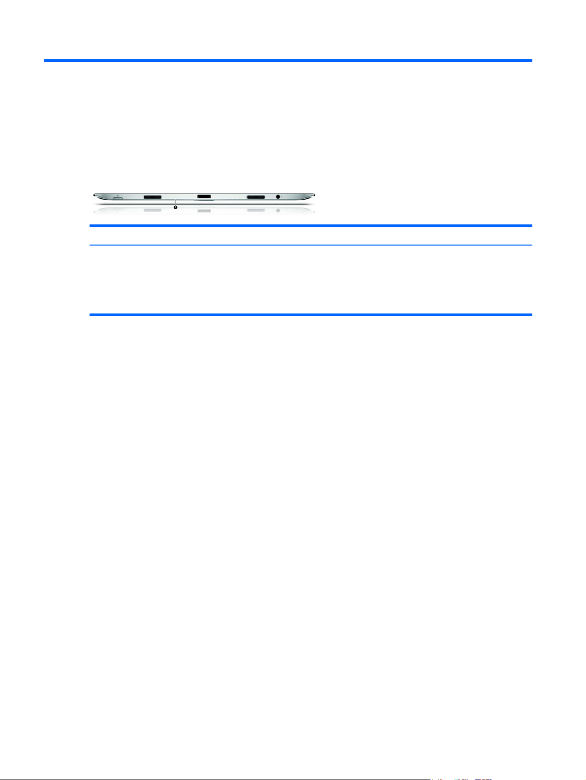
2 External component identification
Tablet edge components
Tablet edge components 3
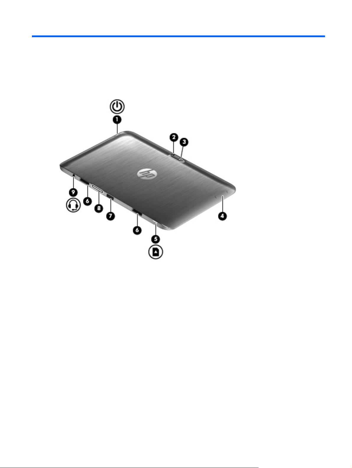
Components Description
(1)
Power button
When the computer is off, press the button to turn on
●
the tablet.
When the computer is on, press the button briefly to
●
initiate Sleep.
When the computer is in the Sleep state, press the
●
button briefly to exit Sleep.
CAUTION: Pressing and holding down the power button
will result in the loss of unsaved information.
If the computer has stopped responding and
●
Microsoft® Windows® shutdown procedures are
ineffective, press and hold the power button down for
at least 5 seconds to turn off the tablet.
Swipe from the right edge of the TouchPad or
touch screen to display the charms, tap Search, and then
tap the search box. In the search box, type power, select
Settings, and then select Power options, or see the User
Guide.
– or –
To learn more about your power settings, on the
Start screen, type p. In the search box, type power, select
Settings, and then select Power options, or see the User
Guide.
(2) Camera light (rear) Provides flash lighting for the camera.
(3) Webcam (rear) Records video, captures still photographs, and allows
(4) Volume button Controls speaker volume on the tablet.
(5) Micro SD Card Reader Supports micro SD cards.
(6) Alignment post connectors (2) Align and attach the tablet to the keyboard dock.
(7) Docking port/power connector Connects the tablet to the keyboard dock and connects an
video conferences and online chat by means of streaming
video.
To use the webcam, type c, and then select Camera.
To increase speaker volume, press the + edge of the
●
button.
To decrease speaker volume, press the – edge of the
●
button.
AC adapter.
4 Chapter 2 External component identification

Components Description
(8) System information Displays serial number, product number, warranty, and
(9)
Audio-out (headphone) jack/Audio-in
(microphone) jack
regulatory and wireless certification information.
Connects optional powered stereo speakers, headphones,
earbuds, a headset, or a television audio cable.
WARNING! To reduce the risk of personal injury, adjust
the volume before using headphones, earbuds, or a
headset. For additional safety information, see the
Regulatory, Safety and Environmental Notices.
NOTE: When a device is connected to the jack, the
computer speakers are disabled.
NOTE: Be sure that the device cable has a 4-conductor
connector that supports both audio-out (headphone) and
audio-in (microphone).
NOTE: Stand-alone microphones and headphones with
separate microphone jacks are not supported.
Tablet edge components 5
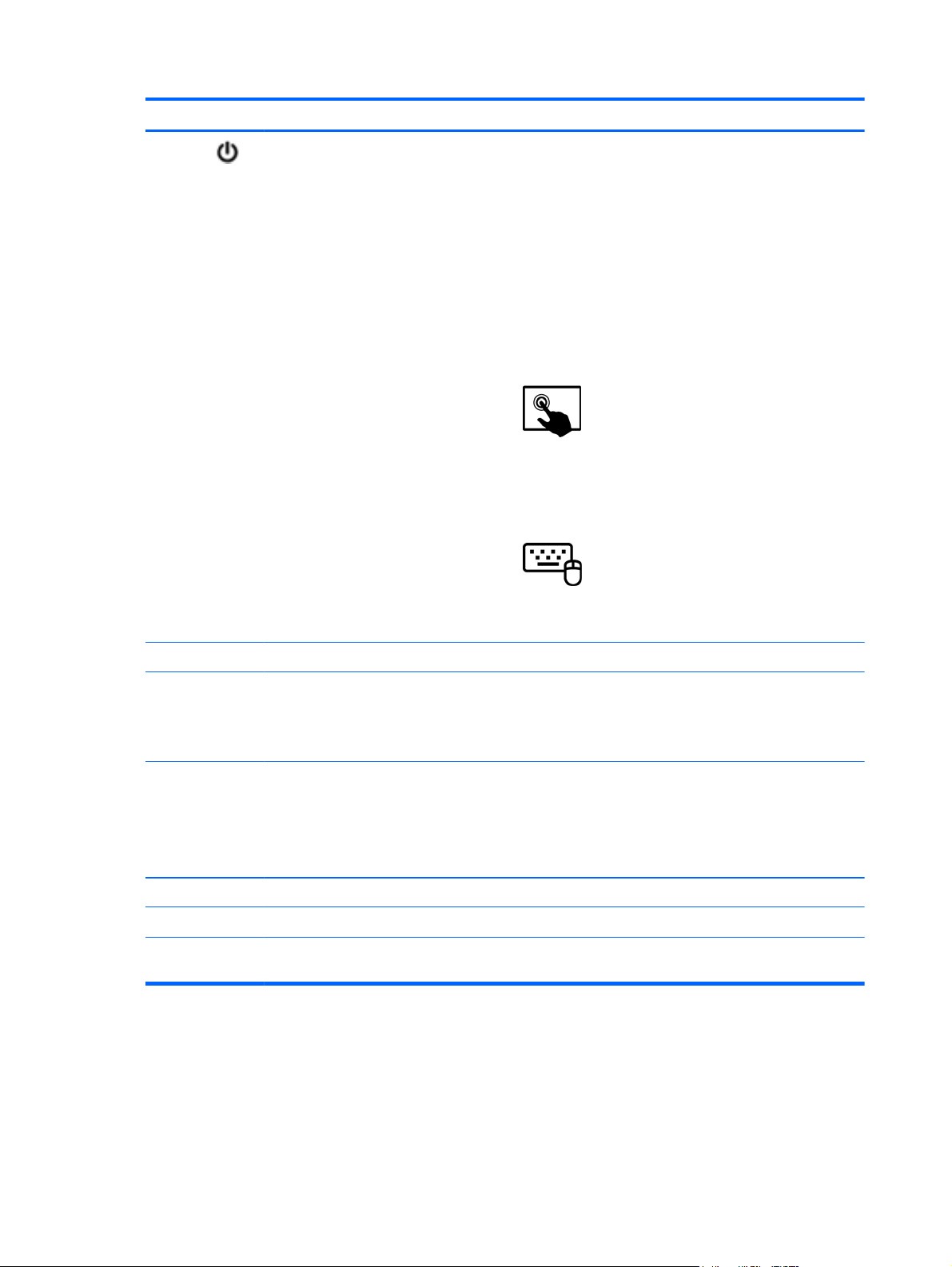
Display
Component Description
(1) WLAN antennas (2)* Send and receive wireless signals.
(2) Internal microphones (2) Record audio, automatically filtering out the noise around you and cancelling
(3) Webcam (front) Records video and takes still photographs.
(4) Webcam light (front) On: The webcams are on.
(5) Ambient light sensor The ambient light sensor automatically adjusts the display brightness based
(6) Speakers (2) Produce sound.
(7) Windows® logo button Minimizes all open applications and displays the Start screen.
echoes.
Swipe from the right edge of the TouchPad or touch screen to
display the charms, tap Search, and then tap the search box. Type c, and
then select Camera from the list of applications.
– or –
From the Start screen, type c, and then select Camera from the
list of applications.
on the lighting conditions in your environment.
6 Chapter 2 External component identification

Component Description
(8) Near Field Communication (NFC)
antenna
*The antennas are not visible from the outside of the computer. For optimal transmission, keep the areas immediately
around the antennas and proximity sensors free from obstructions. For wireless regulatory notices, see the section of the
Regulatory, Safety, and Environmental Notices that applies to your country or region.
With HP TouchZone, you can wirelessly connect, communicate and transfer
data/info to and from your Near Field Communication (NFC)-compatible
devices.
Display 7
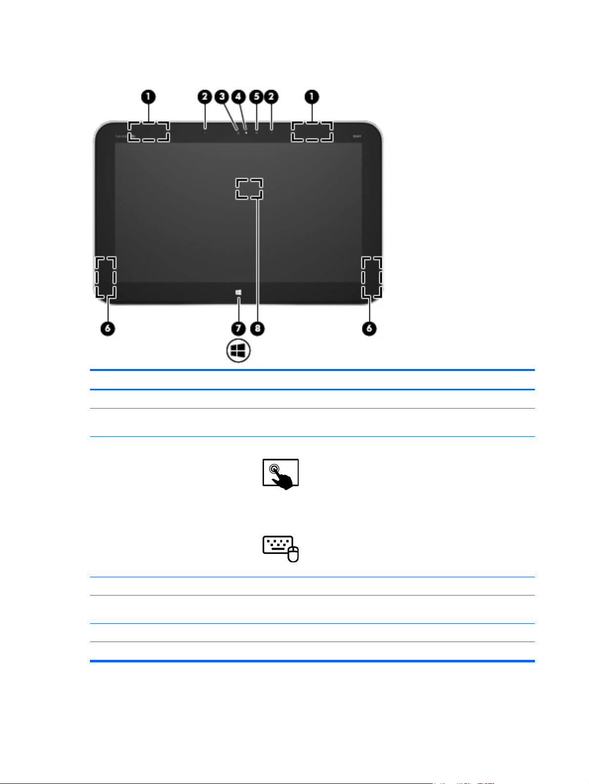
Keyboard dock
Top
Component Description
(1) Alignment posts Align and attach the tablet to the keyboard dock.
(2) Release latch Releases the tablet. To release the tablet, slide the
(3) Docking connector Connects the tablet to the keyboard dock.
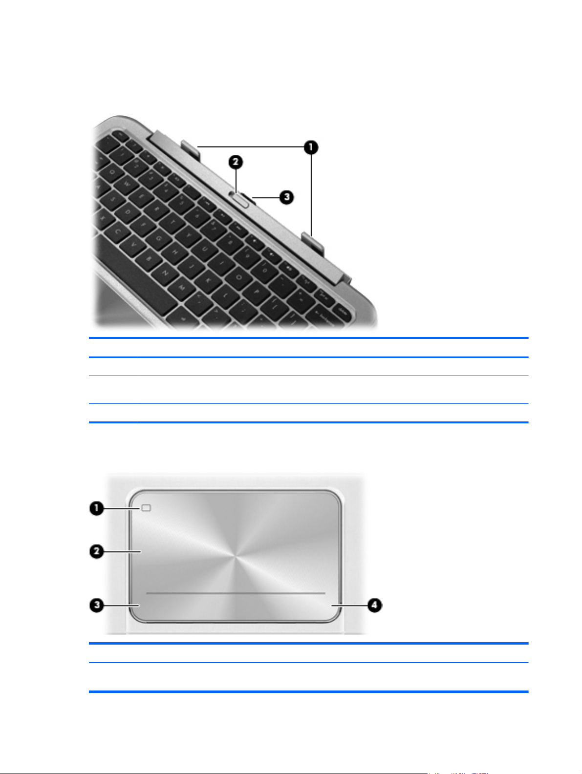
TouchPad
release latch to the left.
Component Description
(1) TouchPad on/off button Turns the TouchPad off or on when you double-tap the
8 Chapter 2 External component identification
button.
Component Description
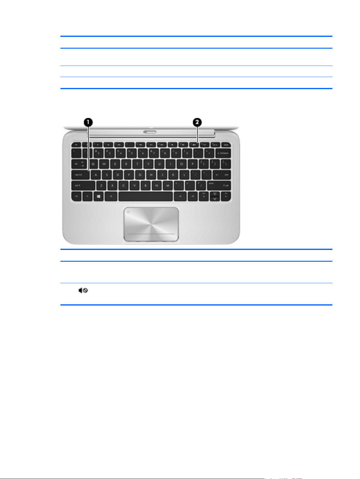
Lights
(2) TouchPad zone Reads your finger gesture to move the pointer or activate
items on the screen.
(3) Left TouchPad button Functions like the left button of an external mouse.
(4) Right TouchPad button Functions like the right button on an external mouse.
Component Description
(1) Caps lock light
(2)
Mute light ● Amber: Computer sound is off.
White: Caps lock is on.
●
Off: Caps lock is off.
●
Off: Computer sound is on.
●
Keyboard dock 9
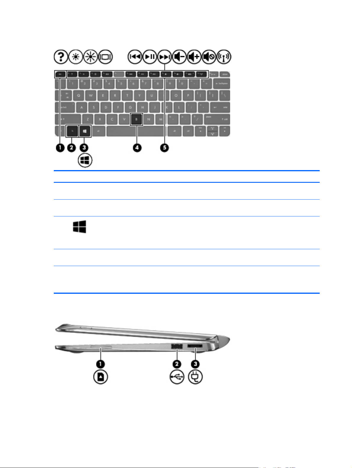
Keys
Component Description
(1) esc key Displays system information when pressed in combination with the
(2) fn Displays system information when pressed in combination with the
(3)
(4) b key Enables or disables Beats Audio when pressed in combination with
(5) Action keys Perform common tasks.
Right side
fn key.
esc key.
Windows button Returns you to the Start screen from an open app or the Windows
desktop.
NOTE: Pressing the Windows button again will return you to the
previous screen.
the fn key.
NOTE: Action keys do not display or function on the on-screen
keyboard of the tablet.
10 Chapter 2 External component identification
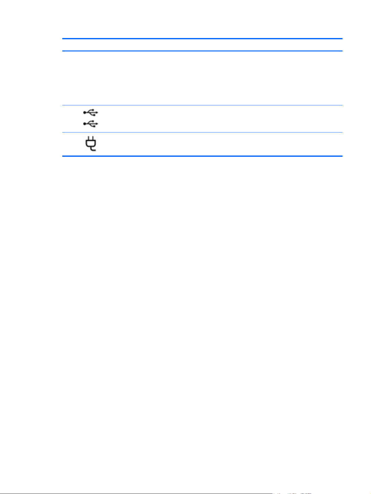
Component Description
(1) Digital Media Slot Supports the following digital card formats:
Secure Digital (SD) Memory Card
●
Secure Digital Extended Capacity (SDxC) Memory Card
●
Secure Digital High Capacity (SDHC) Memory Card
●
● Ultra High Speed MultiMediaCard (UHS/MMC)
(2)
(3)
USB 2.0 port Connects an optional USB device.
Power connector Connects an AC adapter.
Keyboard dock 11

Left side
Component Description
(1)
(2)
(3)
HDMI port Connects an optional video or audio device, such as a high-
definition television, any compatible digital or audio component,
or a high-speed HDMI device.
USB 2.0 port Connects an optional USB device.
Audio-out (headphone) jack/Audio-in
(microphone) jack
Connects optional powered stereo speakers, headphones,
earbuds, a headset, or a television audio cable. Also connects
an optional headset microphone.
WARNING! To reduce the risk of personal injury, adjust the
volume before using headphones, earbuds, or a headset. For
additional safety information, see the Regulatory, Safety and
Environmental Notices.
NOTE: When a device is connected to the jack, the computer
speakers are disabled.
NOTE: Be sure that the device cable has a 4-conductor
connector that supports both audio-out (headphone) and audioin (microphone).
NOTE: Stand-alone microphones and headphones with
separate microphone jacks are not supported.
12 Chapter 2 External component identification
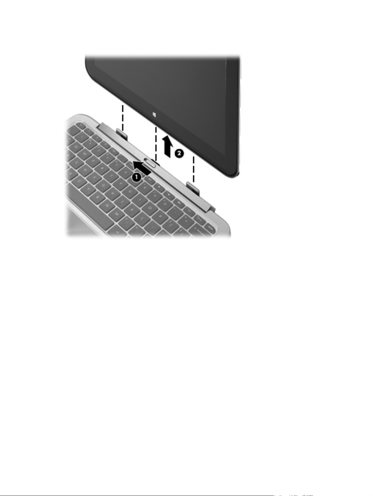
Releasing the tablet from the keyboard dock
To release the tablet from the keyboard dock, follow these steps:
1. Slide the release latch on the keyboard dock to the left (1).
2. Lift and remove the tablet (2).
Keyboard dock 13
3 Illustrated parts catalog
Locating system information
Important system information is located on the bottom edge of the tablet. You may need the
information when traveling internationally or when you contact support:
Item Description
(1)
Using Windows, briefly press the fn+esc key combination to display the System Information screen,
which provides the product name and serial number of your computer, as well as information about
the memory, processor, BIOS, and keyboard.
Serial number
●
Product number
●
Warranty period
●
Regulatory and wireless certification information
●
14 Chapter 3 Illustrated parts catalog
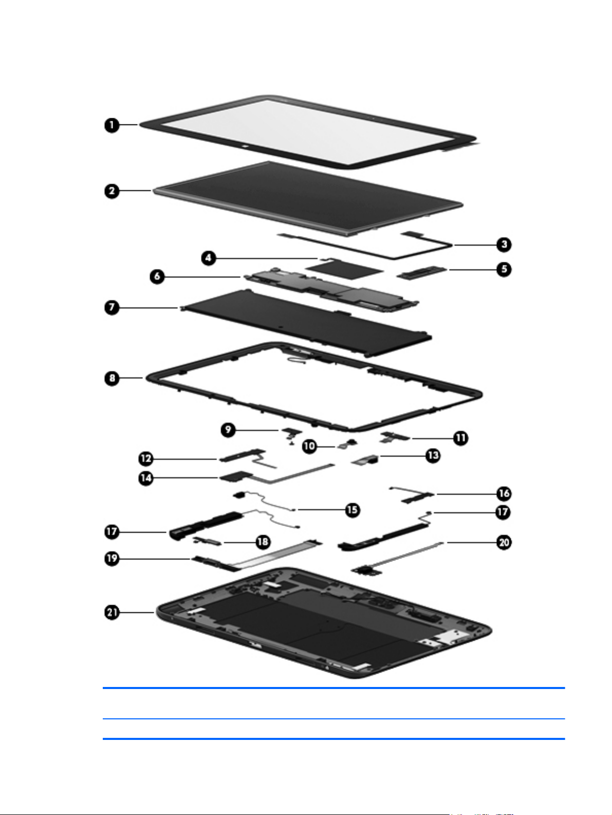
Computer major components
Item Component Spare part
number
(1) Touch screen (with cables) 702353-001
Computer major components 15

Item Component Spare part
number
(2) Display panel 702362–001
(3) Display panel cable 702351 –001
(4) NFC antenna 702347-001
(5) System board (includes keyboard cable):
64 (GB) 702366–001
64 (GB) W8 Standard 702366–501
64 (GB) W8 Pro 702366–601
128 (GB) 708759–001
128 (GB) W8 Standard 708759–501
128 (GB) W8 Pro 708759–601
(6) TouchScreen connector board (with cable) 702351-001
(7) Battery (with cable)
2–cell 25W Hr 3.38AH battery (Tablet) 694501–001
2–cell 21W Hr 2.86AH battery (Keyboard dock) 694502–001
(8) Display bezel (with left antenna transceiver) 702350–001
(9) Microphone board (with cable) 702358–001
(10) Webcam (front) with cable 702358–001
(11) Camera LED board 702358–001
(12) Volume control button board (with cable) in back cover 64G kit 702356–001
(13) Rear camera (with cable) 702358–001
(14) Power button board 702360–001
(15) Vibration module (with cable) 702356–001
(16) Speakers (with cables) 702365–001
(17) Micro SD digital media card board 702359–001
(18) Windows button board (with cable) 702356–001
(19) Audio/micro SD digital media card reader/touch screen board with cable 702357–001
(20) Multimedia board (keyboard dock) 702361-001
(21) Base enclosure (with right antenna transceiver) 702349–001
16 Chapter 3 Illustrated parts catalog
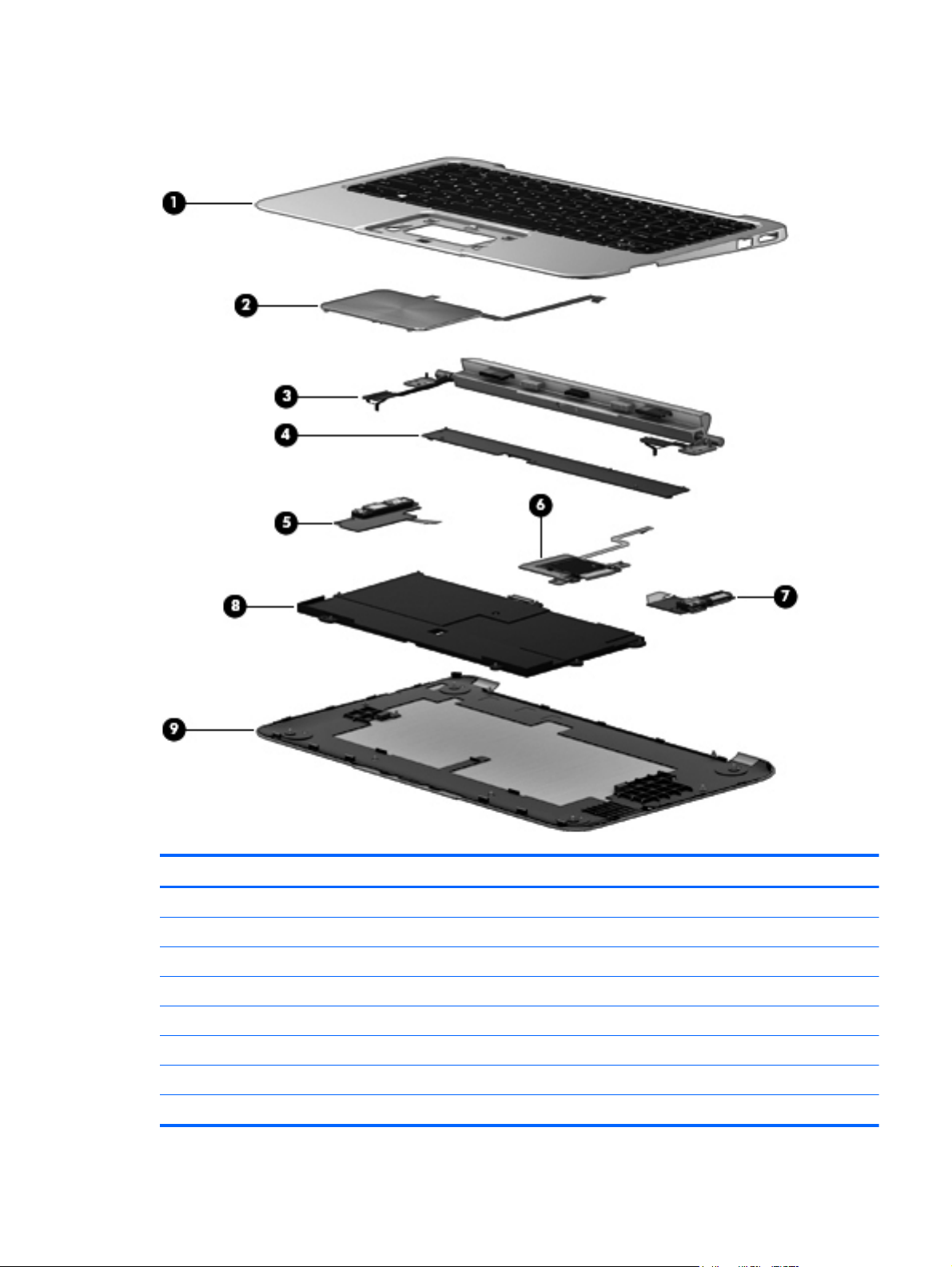
Keyboard dock parts
Item Component Spare part number
(1) Top cover/keyboard
Top cover with keyboard for use in the United States 702369-001
Top cover with keyboard for use in the United Kingdom and Singapore 702369-031
Top cover with keyboard for use in Germany 702369-041
Top cover with keyboard for use in France 702369-051
Top cover with keyboard for use in Italy 702369-061
Top cover with keyboard for use in Spain 702369-071
Top cover with keyboard for use in Portugal 702369-131
Keyboard dock parts 17

Item Component Spare part number
Top cover with keyboard for use in Turkey 702369-141
Top cover with keyboard for use in Greece 702369-151
Top cover with keyboard for use in Latin America 702369-161
Top cover with keyboard for use in Saudi Arabia 702369–171
Top cover with keyboard for use in Russia 702369–251
Top cover with keyboard for use in Thailand 702369–281
Top cover with keyboard for use in Japan 702369–291
Top cover with keyboard for use in Belgium 702369–A41
Top cover with keyboard for use in Taiwan 702369–AB1
Top cover with keyboard for use in South Korea 702369–AD1
Top cover with keyboard for use in Switzerland 702369–BG1
Top cover with keyboard for use in Canada 702369–DB1
Top cover with keyboard for use in Denmark, Finland and Norway 702369–DH1
Top cover with keyboard for use internationally 702369–B31
(2) TouchPad (in Top Cover kit) 702368-001
(3) Hinge assembly 702354-001
(4) System board
System board for KB dock 702367-001
(5) Multimedia board 702361-001
(6) Digital Media Card board 702357-001
(7) Power/USB board 702360-001
(8) Battery
2–cell, 25WHr 3.38AH Li-ion battery (Tablet) 694501-001
2–cell, 21WHr 2.86AH Li-ion battery (Keyboard dock) 694502-001
(9) Display back cover
64–GB 1/1/0 702348–001
128–GB 1/1/0 708757–001
64–GB 2/2/0 709997–001
128–GB 2/2/0 709998-001
128–GB 1/1/0 APJ 710885-001
64–GB 1/1/0 APJ 710884-001
18 Chapter 3 Illustrated parts catalog

Sequential part number listing
Spare part
number
490371–001 Power Cord for use in North America
490371–011 Power Cord for use in Australia
490371–021 Power Cord for use in Europe, the Middle East and Africa
490371–031 Power Cord for use in the United Kingdom and Singapore
490371–061 Power Cord for use in Italy
490371–081 Power Cord for use in Denmark
490371–111 Power Cord for use in Switzerland
490371–201 Power Cord for use in Thailand
490371–291 Power Cord for use in Japan
490371–AA1 Power Cord for use in the People's Republic of China
490371–AB1 Power Cord for use in Taiwan
490371–AD1 Power Cord for use in South Korea
490371–D61 Power Cord for use in India
539614–001 RJ45/USB Adaptor
694501-001 2–cell, 25WHr 3.38AH Li-ion battery
Description
694502-001 2–cell, 21WHr 2.86AH Li-ion battery
701943–001
702347–001 Antenna
702348–001 Display cover
702349–001 Base enclosure
702350–001 Bezel (with antenna)
702351–001 Display cable
702352–001 Keyboard dock for use in the United States
702352–031 Keyboard dock for use in the United Kingdom and Singapore
702352–041 Keyboard dock for use in Germany
702352–051 Keyboard dock for use in France
702352–061 Keyboard dock for use in Italy
702352–071 Keyboard dock for use in Spain
702352–131 Keyboard dock for use in Portugal
702352–141 Keyboard for use in Turkey
702352–151 Keyboard dock for use in Greece
702352-161 Keyboard dock for use in Latin America
Sequential part number listing 19

Spare part
number
702352–171 Keyboard dock for use in Saudi Arabia
702352-251 Keyboard dock for use in Russia
702352–A41 Keyboard dock for use in Belgium
702352–B31 Keyboard dock for use in The Netherlands
702352–BG1 Keyboard dock for use in Switzerland
702352–DB1 Keyboard dock for use in Canada
702352–DH1 Keyboard dock for use in Denmark, Finland, Norway
702353–001 Touch screen
702354–001 Display hinge assembly
Description
702355–001 11.6-in, HD, Anti-Glare WLED display panel for use with 64–GB units in Europe, the
702355–011 11.6-in, HD, Anti-Glare WLED display panel for use with 64–GB units in New Zealand
702355–161 11.6-in, HD, Anti-Glare WLED display panel for use with 64–GB units in Latin America
702355–281 11.6-in, HD, Anti-Glare WLED display panel for use with 64–GB units in Thailand
702355–371 11.6-in, HD, Anti-Glare WLED display panel for use with 64–GB units in Asia Pacific
702355–AA1 11.6-in, HD, Anti-Glare WLED display panel for use with 64–GB units in People's
702355–AB1 11.6-in, HD, Anti-Glare WLED display panel for use with 64–GB units in Taiwan
702355–AC1 11.6-in, HD, Anti-Glare WLED display panel for use with 64–GB units in Hong Kong
702355–D11 11.6-in, HD, Anti-Glare WLED display panel for use with 64–GB units in Chile
702355–D61 11.6-in, HD, Anti-Glare WLED display panel for use with 64–GB units in India
702356–001 Button board (includes vibration module kit)
702357–001 Audio/micro SD digital media card reader/touch screen board kit
702358–001 Webcam
702359–001 Digital media card reader board (for keyboard dock)
702360–001 USB/Power board (for keyboard dock)
Middle East and Africa
Republic of China
702361–001 Multimedia board (for keyboard dock)
702362–001 11.6-in, HD, Anti-Glare WLED display panel for use in all regions
702363-001 Rubber feet kit
702364–001 Screw kit
702365–001 Speakers
702366–001 System board for use only with 64–GB models equipped with an Intel Z2760 1.8GHz
702366–501 System board for use only with 64–GB W8 Standard models equipped with an Intel
20 Chapter 3 Illustrated parts catalog
processor (includes processor and replacement thermal material)
Z2760 1.8GHz processor (includes processor and replacement thermal material)

Spare part
number
Description
702366–601 System board for use only with 64–GB W8 Pro models equipped with an Intel Z2760
1.8GHz processor (includes processor and replacement thermal material)
702367–001 System board keyboard dock
702368–001 TouchPad LED board with cable
702369–001 Top cover with keyboard for use in the United States
702369-031 Top cover with keyboard for use in the United Kingdom
702369-041 Top cover with keyboard for use in Germany
702369-051 Top cover with keyboardfor use in France
702369-061 Top cover with keyboard for use in Italy
702369–071 Top cover with keyboard for use in Spain
702369–131 Top cover with keyboard for use in Portugal
702369–141 Top cover with keyboard for use in Turkey
702369–151 Top cover with keyboard for use in Greece
702369–161 Top cover with keyboard for use in Latin America
702369–171 Top cover with keyboard for use in Saudi Arabia
702369–251 Top cover with keyboard for use in Russia
702369–281 Top cover with keyboard for use in Thailand
702369–291 Top cover with keyboard for use in Japan
702369–A41 Top cover with keyboard for use in Belgium
702369–AB1 Top cover with keyboard for use in Taiwan
702369–AD1 Top cover with keyboard for use in South Korea
702369–B31 Top cover with keyboard for use internationally
702369–BG1 Top cover with keyboard for use in Switzerland
702369–DB1 Top cover for use in Canada
702369–DH1 Top cover with keyboard for use in Denmark, Finland, Norway
704926–001 HP active pen
708757–001 128–GB 11.6 High definition display back cover (128–GB unit)
708758–001 11.6-in, HD, Anti-Glare WLED display panel for use with 128–GB units in Europe, the
Middle East and Africa
708758–011 11.6-in, HD, Anti-Glare WLED display panel for use with 128–GB units in New
Zealand
708758–161 11.6-in, HD, Anti-Glare WLED display panel for use with 128–GB units in Latin America
708758–281 11.6-in, HD, Anti-Glare WLED display panel for use with 128–GB units in Thailand
708758-371 11.6-in, HD, Anti-Glare WLED display panel for use with 128–GB units in Asia Pacific
Sequential part number listing 21

Spare part
number
Description
708758–AA1 11.6-in, HD, Anti-Glare WLED display panel for use with 128–GB units in People's
708758–AB1 11.6-in, HD, Anti-Glare WLED display panel for use with 128–GB units in Taiwan
708758–AC1 11.6-in, HD, Anti-Glare WLED display panel for use with 128–GB units in Hong Kong
708758–D11 11.6-in, HD, Anti-Glare WLED display panel for use with 128–GB units in Chile
708758–D61 11.6-in, HD, Anti-Glare WLED display panel for use with 128–GB units in India
708759–001 System board (Z2760 for 128–GB tablet)
708759–501 System board (Z2760 for 128–GB tablet) W8 Standard
708759–601 System board (Z2760 for 128–GB tablet) W8 Pro
709997–001 64–GB High definition display back cover
709998–001 128–GB High definition display back cover
710884-001 64–GB High definition display back cover
710885-001 128–GB High definition display back cover
714656–001 AD Adapter (non-smart) 20W for use in all countries and regions
716825–011 11.6-in, HD, Anti-Glare WLED display panel for use with 64–GB Pro in New Zealand
716825–D61 11.6-in, HD, Anti-Glare WLED display panel for use with 64–GB Pro in India
716826–011 11.6-in, HD, Anti-Glare WLED display panel 128–GB Pro in New Zealand
Republic of China
716826–D61 11.6-in, HD, Anti-Glare WLED display panel 128–GB Pro in India
22 Chapter 3 Illustrated parts catalog

4 Removal and replacement procedures
CAUTION: This computer does not have user-replaceable parts. Only HP authorized service
providers should perform the removal and replacement procedures described here. Accessing the
internal part could damage the computer or void the warranty.
Preliminary replacement requirements
Tools required
You will need the following tools to complete the removal and replacement procedures:
Flat-bladed screwdriver
●
Magnetic screwdriver
●
Phillips P0 and P1 screwdrivers
●
Service considerations
The following sections include some of the considerations that you must keep in mind during
disassembly and assembly procedures.
NOTE: As you remove each subassembly from the computer, place the subassembly (and all
accompanying screws) away from the work area to prevent damage.
Plastic parts
CAUTION: Using excessive force during disassembly and reassembly can damage plastic parts.
Use care when handling the plastic parts. Apply pressure only at the points designated in the
maintenance instructions.
Cables and connectors
CAUTION: When servicing the computer, be sure that cables are placed in their proper locations
during the reassembly process. Improper cable placement can damage the computer.
Cables must be handled with extreme care to avoid damage. Apply only the tension required to
unseat or seat the cables during removal and insertion. Handle cables by the connector whenever
possible. In all cases, avoid bending, twisting, or tearing cables. Be sure that cables are routed in
such a way that they cannot be caught or snagged by parts being removed or replaced. Handle flex
cables with extreme care; these cables tear easily.
Preliminary replacement requirements 23

Drive handling
CAUTION: Drives are fragile components that must be handled with care. To prevent damage to
the computer, damage to a drive, or loss of information, observe these precautions:
Before removing or inserting a hard drive, shut down the computer. If you are unsure whether
the computer is off or in Hibernation, turn the computer on, and then shut it down through the
operating system.
Before handling a drive, be sure that you are discharged of static electricity. While handling a drive,
avoid touching the connector.
Before removing a diskette drive or optical drive, be sure that a diskette or disc is not in the drive and
be sure that the optical drive tray is closed.
Handle drives on surfaces covered with at least one inch of shock-proof foam.
Avoid dropping drives from any height onto any surface.
After removing a hard drive, an optical drive, or a diskette drive, place it in a static-proof bag.
Avoid exposing an internal hard drive to products that have magnetic fields, such as monitors
or speakers.
Avoid exposing a drive to temperature extremes or liquids.
If a drive must be mailed, place the drive in a bubble pack mailer or other suitable form of protective
packaging and label the package “FRAGILE.”
Grounding guidelines
Electrostatic discharge damage
Electronic components are sensitive to electrostatic discharge (ESD). Circuitry design and structure
determine the degree of sensitivity. Networks built into many integrated circuits provide some
protection, but in many cases, ESD contains enough power to alter device parameters or melt
silicon junctions.
A discharge of static electricity from a finger or other conductor can destroy static-sensitive devices or
microcircuitry. Even if the spark is neither felt nor heard, damage may have occurred.
An electronic device exposed to ESD may not be affected at all and can work perfectly throughout a
normal cycle. Or the device may function normally for a while, then degrade in the internal layers,
reducing its life expectancy.
CAUTION: To prevent damage to the computer when you are removing or installing internal
components, observe these precautions:
Keep components in their electrostatic-safe containers until you are ready to install them.
Before touching an electronic component, discharge static electricity by using the guidelines
described in this section.
Avoid touching pins, leads, and circuitry. Handle electronic components as little as possible.
If you remove a component, place it in an electrostatic-safe container.
The following table shows how humidity affects the electrostatic voltage levels generated by
different activities.
CAUTION: A product can be degraded by as little as 700 V.
24 Chapter 4 Removal and replacement procedures

Typical electrostatic voltage levels
Relative humidity
Event 10% 40% 55%
Walking across carpet 35,000 V 15,000 V 7,500 V
Walking across vinyl floor 12,000 V 5,000 V 3,000 V
Motions of bench worker 6,000 V 800 V 400 V
Removing DIPS from plastic tube 2,000 V 700 V 400 V
Removing DIPS from vinyl tray 11,500 V 4,000 V 2,000 V
Removing DIPS from Styrofoam 14,500 V 5,000 V 3,500 V
Removing bubble pack from PCB 26,500 V 20,000 V 7,000 V
Packing PCBs in foam-lined box 21,000 V 11,000 V 5,000 V
Preliminary replacement requirements 25

Packaging and transporting guidelines
Follow these grounding guidelines when packaging and transporting equipment:
To avoid hand contact, transport products in static-safe tubes, bags, or boxes.
●
Protect ESD-sensitive parts and assemblies with conductive or approved containers or
●
packaging.
Keep ESD-sensitive parts in their containers until the parts arrive at static-free workstations.
●
Place items on a grounded surface before removing items from their containers.
●
Always be properly grounded when touching a component or assembly.
●
● Store reusable ESD-sensitive parts from assemblies in protective packaging or
nonconductive foam.
Use transporters and conveyors made of antistatic belts and roller bushings. Be sure that
●
mechanized equipment used for moving materials is wired to ground and that proper materials
are selected to avoid static charging. When grounding is not possible, use an ionizer to dissipate
electric charges.
Workstation guidelines
Follow these grounding workstation guidelines:
● Cover the workstation with approved static-shielding material.
● Use a wrist strap connected to a properly grounded work surface and use properly grounded
tools and equipment.
Use conductive field service tools, such as cutters, screwdrivers, and vacuums.
●
● When fixtures must directly contact dissipative surfaces, use fixtures made only of static-
safe materials.
Keep the work area free of nonconductive materials, such as ordinary plastic assembly aids
●
and Styrofoam.
Handle ESD-sensitive components, parts, and assemblies by the case or PCM laminate. Handle
●
these items only at static-free workstations.
● Avoid contact with pins, leads, or circuitry.
● Turn off power and input signals before inserting or removing connectors or test equipment.
26 Chapter 4 Removal and replacement procedures

Equipment guidelines
Grounding equipment must include either a wrist strap or a foot strap at a grounded workstation.
When seated, wear a wrist strap connected to a grounded system. Wrist straps are flexible
●
straps with a minimum of one megohm ±10% resistance in the ground cords. To provide proper
ground, wear a strap snugly against the skin at all times. On grounded mats with banana-plug
connectors, use alligator clips to connect a wrist strap.
When standing, use foot straps and a grounded floor mat. Foot straps (heel, toe, or boot straps)
●
can be used at standing workstations and are compatible with most types of shoes or boots. On
conductive floors or dissipative floor mats, use foot straps on both feet with a minimum of one
megohm resistance between the operator and ground. To be effective, the conductive must be
worn in contact with the skin.
The following grounding equipment is recommended to prevent electrostatic damage:
Antistatic tape
●
Antistatic smocks, aprons, and sleeve protectors
●
● Conductive bins and other assembly or soldering aids
Nonconductive foam
●
Conductive tabletop workstations with ground cords of one megohm resistance
●
● Static-dissipative tables or floor mats with hard ties to the ground
● Field service kits
Static awareness labels
●
Material-handling packages
●
● Nonconductive plastic bags, tubes, or boxes
Metal tote boxes
●
Electrostatic voltage levels and protective materials
●
The following table lists the shielding protection provided by antistatic bags and floor mats.
Material Use Voltage protection level
Antistatic plastics Bags 1,500 V
Carbon-loaded plastic Floor mats 7,500 V
Metallized laminate Floor mats 5,000 V
Component replacement procedures
This chapter provides removal and replacement procedures.
There are as many as 77 screws that must be removed, replaced, or loosened when servicing
the computer. Make special note of each screw size and location during removal and replacement.
Dock components
The following sections describe the removal and replacement procedure of the dock components
Component replacement procedures 27

Base enclosure
Description Spare part number
Base enclosure (Black) 702349-001
Rubber feet 702363-001
Before disassembling the keyboard dock, follow these steps:
1. Shut down the keyboard dock. If you are unsure whether the computer is off or in Hibernation,
turn the computer on, and then shut it down through the operating system.
2. Disconnect all external devices connected to the computer.
3. Disconnect the power from the computer by first unplugging the power cord from the AC outlet
and then unplugging the AC adapter from the computer.
Remove the base enclosure:
1. Turn the computer face down, and then remove the rubber feet (1). The rubber feet are attached
with adhesive, and have alignment pins that fit into the screw holes.
2. Remove the 2 3.0-mm screws located under the front rubber feet (2), and then remove the 2
polished 4.5-mm screws on the front row (3).
3. Remove the 2 remaining 4.5-mm screws under rear rubber feet (4).
28 Chapter 4 Removal and replacement procedures

Battery
4. Separate and release the bottom enclosure (1), and then remove the bottom enclosure (2).
Description Spare part number
2-cell, 25WHr 3.38AH Li-ion battery (Tablet) 694501-001
2-cell, 21WHr 2.86AH Li-ion battery (Keyboard dock) 694502-001
Before removing the battery, follow these steps:
1. Shut down the computer. If you are unsure whether the computer is off or in Hibernation, turn
the computer on, and then shut it down through the operating system.
2. Disconnect all external devices connected to the computer.
3. Disconnect the power from the computer by first unplugging the power cord from the AC outlet
and then unplugging the AC adapter from the computer.
4. Remove the base enclosure (see
Base enclosure on page 28).
1. Turn the computer right-side up, with the front toward you.
2. Disconnect the battery cable (1) from the system board, and then remove the 7 screws securing
the battery (2).
Component replacement procedures 29

3. Remove the battery (3).
30 Chapter 4 Removal and replacement procedures

Digital media card reader board
Description Spare part number
Digital media card reader 702359-001
Before removing the digital media card reader, follow these steps:
1. Shut down the computer. If you are unsure whether the computer is off or in Hibernation, turn
the computer on, and then shut it down through the operating system.
2. Disconnect all external devices connected to the computer.
3. Disconnect the power from the computer by first unplugging the power cord from the AC outlet
and then unplugging the AC adapter from the computer.
4. Remove the base enclosure (see
5. Disconnect the battery cable (see
Base enclosure on page 28).
Battery on page 29).
Remove the digital media card reader board and bracket:
1. Disconnect the digital media card reader cable (1).
2. Remove the 2x2–mm broadhead screw on the rear edge of the board and then remove the 2
2x5–mm screws securing the digital media card reader board to the system board (2). The drive
tilts upwards.
3. Remove the digital media card reader board and bracket (3).
Reverse these procedures to reassemble and install the digital media card reader board.
Component replacement procedures 31

USB/Power Connector board
Description Spare part number
USB/Power Connector board 702360-001
Before removing the USB/Power connector board, follow these steps:
1. Shut down the computer. If you are unsure whether the computer is off or in Hibernation, turn
the computer on, and then shut it down through the operating system.
2. Disconnect all external devices connected to the computer.
3. Disconnect the power from the computer by first unplugging the power cord from the AC outlet
and then unplugging the AC adapter from the computer.
4. Remove the base enclosure (see
5. Disconnect the battery cable (see
Base enclosure on page 28).
Battery on page 29).
Remove the USB/Power connector board:
1. Disconnect the USB/Power connector board cable (1).
2. Remove the 3 screws securing the USB/Power connector (2).
3. Remove the USB/Power connector board (3).
Reverse this procedure to install the USB/Power connector board and cable.
32 Chapter 4 Removal and replacement procedures

Multimedia board
Description Spare part number
Multimedia board 702361-001
Before removing the multimedia board (which includes USB, Audio, and HDMI connectors), follow
these steps:
1. Shut down the computer. If you are unsure whether the computer is off or in Hibernation, turn
the computer on, and then shut it down through the operating system.
2. Disconnect all external devices connected to the computer.
3. Disconnect the power from the computer by first unplugging the power cord from the AC outlet
and then unplugging the AC adapter from the computer.
4. Remove the base enclosure (see
5. Disconnect the battery cable (see
Base enclosure on page 28).
Battery on page 29.)
Remove the multimedia board:
1. Turn the computer, with the right side toward you, and then disconnect the right assembly hinge
(1).
2. Disconnect the multimedia board cable (2).
3. Remove the three screws (3), and then remove the board (4).
Reverse this procedure to install the multimedia board and cable.
Component replacement procedures 33

Hinge assembly removal
Description Spare part number
Hinge assembly 702354-001
Before removing the hinge, follow these steps:
1. Shut down the computer. If you are unsure whether the computer is off or in Hibernation, turn
the computer on, and then shut it down through the operating system.
2. Disconnect all external devices connected to the computer.
3. Disconnect the power from the computer by first unplugging the power cord from the AC outlet
and then unplugging the AC adapter from the computer.
4. Remove the base enclosure (see
5. Disconnect the battery cable (see
Base enclosure on page 28).
Battery on page 29).
Remove the hinge assembly:
1. Disconnect the hinge assembly left cable (1), and then disconnect the hinge assembly right
cable (2).
NOTE: The right hinge assembly cable may will already be disconnected if the multimedia
board has been removed.
2. Remove the two 5.0-mm screws (3) on the outside screw hole, and then remove the 2 3.0-mm
screws (4) on the inside screw hole.
3. Remove the hinge assembly (5). When removing the hinge assembly, make sure you account
for the hinge assembly right cable (6).
Reverse this procedure to install the hinge assembly.
34 Chapter 4 Removal and replacement procedures

Top cover with keyboard (includes) TouchPad module
Description Spare part number
TouchPad board (includes cable) 702368-001
Top cover with keyboard for use in the United States 702369-001
Top cover with keyboard for use in the United Kingdom and Singapore 702369-031
Top cover with keyboard for use in Germany 702369-041
Top cover with keyboard for use in France 702369-051
Top cover with keyboard for use in Italy 702369-061
Top cover with keyboard for use in Spain 702369-061
Top cover with keyboard for use in Spain 702369-071
Top cover with keyboard for use in Portugal 702369-131
Top cover with keyboard for use in Turkey 702369-141
Top cover with keyboard for use in Greece 702369-151
Top cover with keyboard for use in Latin America 702369-161
Top cover with keyboard for use in Saudi Arabia 702369–171
Top cover with keyboard for use in Russia 702369–251
Top cover with keyboard for use in Thailand 702369–281
Top cover with keyboard for use in Japan 702369–291
Top cover with keyboard for use in Belgium 702369–A41
Top cover with keyboard for use in Taiwan 702369–AB1
Top cover with keyboard for use in South Korea 702369–AD1
Top cover with keyboard for use in Internationally 702369–B31
Top cover with keyboard for use in Switzerland 702369–BG1
Top cover with keyboard for use in Canada 702369–DB1
Top cover with keyboard for use in Denmark, Finland and Norway 702369–DH1
Before removing the TouchPad button board, follow these steps:
1. Shut down the computer. If you are unsure whether the computer is off or in Hibernation, turn
the computer on, and then shut it down through the operating system.
2. Disconnect all external devices connected to the computer.
3. Disconnect the power from the computer by first unplugging the power cord from the AC outlet
and then unplugging the AC adapter from the computer.
4. Remove the display panel (see
Display panel assembly and Battery on page 40).
5. Remove the base enclosure (see
Base enclosure on page 28).
Component replacement procedures 35

Remove the TouchPad button board and cable:
1. Turn the top cover upside down, with the back edge toward you.
2. Disconnect the TouchPad cable (1) and release the metal tape (2).
3. Remove the two Phillips PM screws, and then remove the TouchPad tab.
4. Remove the TouchPad.
Reverse this procedure to install the TouchPad button board and cable.
36 Chapter 4 Removal and replacement procedures

System board
NOTE: The system board spare part kit includes replacement thermal material.
Description Spare part number
For use only with computer models equipped with 64–GB devices 702366–001
For use only with W8 Standard computer models equipped with 64–GB devices 702366-501
For use only with W8 Pro computer models equipped with 64–GB devices 702366–601
System board for keyboard dock 702367–001
System board for use only with 64–GB models equipped with an Intel Z2760 1.8GHz processor
(includes processor and replacement thermal material)
System board for use only with 64–GB W8 Standard models equipped with an Intel Z2760 1.8GHz
processor (includes processor and replacement thermal material)
System board for use only with 64–GB W8 Pro models equipped with an Intel Z2760 1.8GHz
processor (includes processor and replacement thermal material)
702366–001
702366–501
702366–601
Before removing the system board, follow these steps:
1. Shut down the computer. If you are unsure whether the computer is off or in Hibernation, turn
the computer on, and then shut it down through the operating system.
2. Disconnect all external devices connected to the computer.
3. Disconnect the power from the computer by first unplugging the power cord from the AC outlet
and then unplugging the AC adapter from the computer.
4. Remove the base enclosure (see
5. Remove the battery (see
Battery on page 29).
Base enclosure on page 28).
Remove the system board:
1. Remove the following cables:
Power connector/USB/Audio board cable (1)
●
● Digital card media reader cable (2)
Hinge assembly left cable(3)
●
TouchPad cable (4)
●
Keyboard cable (5)
●
Multimedia board cable (6)
●
Component replacement procedures 37

2. Remove the 5 Phillips PM 2.0x3.0 screws (1).
3. Remove the system board (2).
Reverse this procedure to install the system board.
Tablet parts
The following sections show the removal and replacement procedures for the tablet parts.
38 Chapter 4 Removal and replacement procedures

NOTE: Any time the internal tablet components are repaired, the display bezel should be replaced.
Component replacement procedures 39

Display panel assembly and Battery
NOTE: When disassembling or assembling the display panel, it is necessary to operate in a clean
environment such as a clean room or clean work table.
Description Spare part number
2–cell 25WHr 3.38 AH Li-ion battery 694501–001
11.6-in, HD, Anti-Glare WLED display panel for use in all regions 702362-001
11.6-in, HD, Anti-Glare WLED display panel for use with 64–GB units in Europe, the Middle
East and Africa
11.6-in, HD, Anti-Glare WLED display panel for use with 64–GB units in New Zealand 702355–011
11.6-in, HD, Anti-Glare WLED display panel for use with 64–GB units in Latin America 702355-161
11.6-in, HD, Anti-Glare WLED display panel for use with 64–GB units in Thailand 702355–281
11.6-in, HD, Anti-Glare WLED display panel for use with 64–GB units in Asia Pacific 702355-371
11.6-in, HD, Anti-Glare WLED display panel for use with 64–GB units in People's Republic of
China
11.6-in, HD, Anti-Glare WLED display panel for use with 64–GB units in Taiwan 702355–AB1
11.6-in, HD, Anti-Glare WLED display panel for use with 64–GB units in Hong Kong 702355–AC1
11.6-in, HD, Anti-Glare WLED display panel for use with 64–GB units in Chile 702355–D11
11.6-in, HD, Anti-Glare WLED display panel for use with 64–GB units in India 702355–D61
11.6-in, HD, Anti-Glare WLED display panel for use with 128–GB units in Europe, the Middle
East and Africa
11.6-in, HD, Anti-Glare WLED display panel for use with 128–GB units in New Zealand 708758–011
11.6-in, HD, Anti-Glare WLED display panel for use with 128–GB units in Latin America 708758-161
11.6-in, HD, Anti-Glare WLED display panel for use with 128–GB units in Asia Pacific 708758–371
11.6-in, HD, Anti-Glare WLED display panel for use with 128–GB units in People's Republic
of China
702355-001
702355–AA1
708758-001
708758–AA1
11.6-in, HD, Anti-Glare WLED display panel for use with 128–GB units in Taiwan 708758–AB1
11.6-in, HD, Anti-Glare WLED display panel for use with 128–GB units in Hong Kong 708758–AC1
11.6-in, HD, Anti-Glare WLED display panel for use with 128–GB units in Chile 708758–D11
11.6-in, HD, Anti-Glare WLED display panel for use with 128–GB units in India 708758–D61
11.6-in, HD, Anti-Glare WLED display panel for use with 64–GB Pro units in New Zealand 716825–011
11.6-in, HD, Anti-Glare WLED display panel for use with 64–GB Pro units in India 716825–D61
11.6-in, HD, Anti-Glare WLED display panel for use with 128–GB Pro units in New Zealand 716826–011
11.6-in, HD, Anti-Glare WLED display panel for use with 128–GB Pro units in India 716826–D61
40 Chapter 4 Removal and replacement procedures

Before removing the display panel, follow these steps:
1. Shut down the computer. If you are unsure whether the computer is off or in Hibernation, turn
the computer on, and then shut it down through the operating system.
2. Disconnect all external devices connected to the computer.
3. Disconnect the power from the computer by first unplugging the power cord from the AC outlet
and then unplugging the AC adapter from the computer.
Remove the display panel:
1. Turn the computer right-side up, with the rear toward you.
2. Open the computer.
3. Disconnect the tablet from the keyboard dock (see
Releasing the tablet from the keyboard dock
on page 13).
4. Apply the heat gun to locations on the surface of the touch screen.
NOTE: Ensure that the temperature is kept at an appropriate level to avoid damaging internal
components. Glue melts at 80 degrees Celsius.
Component replacement procedures 41

5. Release the touch screen.
NOTE: Be careful not to scratch the screen.
6. Remove the 5 2x3–mm screws securing the panel to the display assembly (2 on the top edge, 1
on the right side, and 2 on the left side).
42 Chapter 4 Removal and replacement procedures

7. Lift up on the top edge of the display.
NOTE: Support the display panel as you are removing the screws.
8. Locate the NFC antenna connector (1), disconnect the NFC antenna cable (2), and then remove
the NFC antenna (3).
Component replacement procedures 43

9. Disconnect the tablet battery cable (1), remove the 4 screws that secure the battery (2), and
then remove the tablet battery (3).
10. Release the display panel cable support strip (1), release the display panel cable tape (2), and
then disconnect the display panel cable (3).
44 Chapter 4 Removal and replacement procedures

11. Clear the routing channel and clips (4), and then remove the display panel (5).
12. Locate the display panel cable support strip (1), release the display panel cable tape (2), and
then disconnect the display panel cable (3).
Component replacement procedures 45

13. Lift up on the right side of the screen. From the left side, locate the 2 connectors (1), and then
release the connectors (2). Remove the touch screen (3)
Reverse this procedure to install the display panel.
System board
Component Spare part number
System board for use only with 128–GB tablet equipped with an Intel Z2760 1.8GHz processor
(includes processor and replacement thermal material)
System board (Windows 8 Standard) for use only with 128–GB tablet equipped with an Intel Z2760
1.8GHz processor (includes processor and replacement thermal material)
System board (Windows 8 Professional) for use only with 128–GB tablet equipped with an Intel
Z2760 1.8GHz processor (includes processor and replacement thermal material)
Before removing the system board, follow these steps:
1. Shut down the computer. If you are unsure whether the computer is off or in Hibernation, turn
the computer on, and then shut it down through the operating system.
2. Disconnect all external devices connected to the computer.
3. Disconnect the power from the computer by first unplugging the power cord from the AC outlet
and then unplugging the AC adapter from the computer.
Remove the system board:
708759–001
708759–501
708759–601
1. Disconnect the wireless antenna cable (1), the microphone board cable (2), and then disconnect
the webcam cables (3).
46 Chapter 4 Removal and replacement procedures

2. Disconnect the webcam light board cable (4), the power button board cable (5), and then
disconnect the right speaker cable (6).
3. Disconnect the volume control button board cable (1), the micro Digital Media Card Reader
board cable (2), and then disconnect the left speaker cable (3).
Component replacement procedures 47

4. Disconnect the stabilizer module cable (4), disconnect the docking connector board cable (5),
and then disconnect the touch screen connector board cable (6).
5. Remove the five screws securing the system board (1), and then remove the system board (2).
Reverse this procedure to install the system board.
48 Chapter 4 Removal and replacement procedures

Touch screen connector board
Description Spare part number
Touch screen connector board 702351–001
Before removing the touch screen connector board, follow these steps:
1. Shut down the computer. If you are unsure whether the computer is off or in Hibernation, turn
the computer on, and then shut it down through the operating system.
2. Disconnect all external devices connected to the computer.
3. Disconnect the power from the computer by first unplugging the power cord from the AC outlet
and then unplugging the AC adapter from the computer.
Remove the Touch screen:
1. Locate the Touch Screen connector board (1) on the system board, and then disconnect the
touch screen connector board cable (2) from the system board.
2. Remove the screw securing the touch screen connector board (3), and then remove the touch
screen connector board (4).
Display bezel
Description Spare part number
Display bezel (with antenna) 702350-001
Component replacement procedures 49

Before removing the display bezel, follow these steps:
1. Shut down the computer. If you are unsure whether the computer is off or in Hibernation, turn
the computer on, and then shut it down through the operating system.
2. Disconnect all external devices connected to the computer.
3. Disconnect the power from the computer by first unplugging the power cord from the AC outlet
and then unplugging the AC adapter from the computer.
4. Remove the base enclosure (see
5. Remove the display panel, and display panel cable (see
Base enclosure on page 28).
Display panel assembly and Battery
on page 40).
6. Remove the NFC antenna (see
7. Remove the touch screen (see
Display panel assembly and Battery on page 40).
Touch screen connector board on page 49).
Remove the display bezel:
1. Turn the tablet so that it faces forward.
2. Disconnect the left wireless antenna cable (1), and then disconnect the microphone board cable
(2).
3. Disconnect the right webcam cable (3), and then disconnect the webcam LED board cable (4)
4. Disconnect the front webcam cable (5), the front webcam light cable (6), and then disconnect the
Windows button' cable (7).
50 Chapter 4 Removal and replacement procedures

5. Remove the ten screws securing the display bezel.
6. Release the bezel's bottom edge (1), release the left and right edges (2), release the top edge
(3), and remove the display bezel (4).
Reverse this procedure to install the display bezel.
Webcam assembly (front)
Description Spare part numbers
Webcam assembly 702358-001
Before removing the webcam assembly:
1. Shut down the computer. If you are unsure whether the computer is off or in Hibernation, turn
the computer on, and then shut it down through the operating system.
2. Disconnect all external devices connected to the computer.
3. Disconnect the power from the computer by first unplugging the power cord from the AC outlet
and then unplugging the AC adapter from the computer.
4. Remove the display panel (see
Display panel assembly and Battery on page 40).
Component replacement procedures 51

5. Remove the base enclosure (see Base enclosure on page 28).
6. Remove the display bezel (see
Display bezel on page 49).
Remove the front webcam assembly:
1. Remove the 2 screws securing the webcam LED board (1) to the display bezel, and then
remove the webcam LED board (2).
52 Chapter 4 Removal and replacement procedures

2. Remove the from webcam.
3. Remove the screw securing the microphone board (1), and then remove the board (2).
Component replacement procedures 53

4. Locate the volume control button board connector (1), and then disconnect the volume control
button board cable (2). Remove the two screws securing the volume control button board (3),
and then remove the volume control button board (4).
5. Remove the rear cam.
54 Chapter 4 Removal and replacement procedures

Audio/micro SD digital media card reader/touch screen board
Description Spare part number
Audio/micro SD digital media card reader/touch screen board 702357–001
Before removing the Audio/micro SD digital media card reader/touch screen board, follow these
steps:
1. Shut down the computer. If you are unsure whether the computer is off or in Hibernation, turn
the computer on, and then shut it down through the operating system.
2. Disconnect all external devices connected to the computer.
3. Disconnect the power from the computer by first unplugging the power cord from the AC outlet
and then unplugging the AC adapter from the computer.
4. Remove the display panel (see
5. Remove the base enclosure (see
6. Disconnect the battery cable (see
Display panel assembly and Battery on page 40).
Base enclosure on page 28).
Battery on page 29).
To remove the Audio/micro SD digital media card reader/touch screen board:
1. Turn the top cover upside down, with the back edge toward you.
2. Disconnect the Audio cable (1), and remove the Audio board (2).
Component replacement procedures 55

USB/Power button board
Description Spare part number
USB/Power button board 689944-001
Before removing the USB/Power button board, follow these steps:
1. Shut down the computer. If you are unsure whether the computer is off or in Hibernation, turn
the computer on, and then shut it down through the operating system.
2. Disconnect all external devices connected to the computer.
3. Disconnect the power from the computer by first unplugging the power cord from the AC outlet
and then unplugging the AC adapter from the computer.
4. Remove the display panel (see
5. Remove the base enclosure (see
6. Disconnect the battery cable (see
Display panel assembly and Battery on page 40).
Base enclosure on page 28).
Battery on page 29).
Remove the Power button board and cable:
1. Turn the top cover upside down, with the back edge toward you.
2. Locate the USB/Power button board cable (1), and then disconnect the USB/Power button board
cable (2).
3. Remove the 2 Phillips PM screws securing the USB/Power button board to the top cover (3).
4. Remove the USB/Power button board (4).
56 Chapter 4 Removal and replacement procedures

5. Disconnect the vibration module cable from the system board (1), release the vibration module
cable from the routing clips (2), and then remove the vibration module and cable (3).
Speakers
Description Spare part number
Speakers 702365-001
1. Shut down the computer. If you are unsure whether the computer is off or in Hibernation, turn
the computer on, and then shut it down through the operating system.
2. Disconnect all external devices connected to the computer.
3. Disconnect the power from the computer by first unplugging the power cord from the AC outlet
and then unplugging the AC adapter from the computer.
4. Remove the display panel (see
Display panel assembly and Battery on page 40).
Before removing the speakers, follow these steps:
1. Remove the base enclosure (see
2. Disconnect the battery cable (see
Base enclosure on page 28).
Battery on page 29).
Remove the speakers:
1. Turn the top cover upside down, with the back edge toward you.
2. Disconnect the speaker cable from the system board (1), and then release the left speaker cable
from the clips (2).
Component replacement procedures 57

3. Remove the Phillips PM screw securing the speaker to the system board (3), and then remove
the speakers (4).
Micro SD digital media board
Description Spare part number
Micro SD digital media board 702357-001
Before removing the micro SD digital media reader card, follow these steps:
1. Shut down the computer. If you are unsure whether the computer is off or in Hibernation, turn
the computer on, and then shut it down through the operating system.
2. Disconnect all external devices connected to the computer.
3. Disconnect the power from the computer by first unplugging the power cord from the AC outlet
and then unplugging the AC adapter from the computer.
58 Chapter 4 Removal and replacement procedures

Remove the top cover from the display:
1. To remove the micro SD digital media card, locate the micro SD digital media board cable (1),
and then disconnect the cable (2).
2. Locate the micro SD digital media board release points (3), remove the 2 screws (4), and then
remove the board (5).
Power button board
Description Spare part number
Power button board 702360-001
Before removing the power button board, follow these steps:
1. Shut down the computer. If you are unsure whether the computer is off or in Hibernation, turn
the computer on, and then shut it down through the operating system.
2. Disconnect all external devices connected to the computer.
3. Disconnect the power from the computer by first unplugging the power cord from the AC outlet
and then unplugging the AC adapter from the computer.
Component replacement procedures 59

4. To remove power button board , disconnect the power button board cable (1), and then remove
the cable (2).
60 Chapter 4 Removal and replacement procedures

5 Setup Utility (BIOS) and System
Diagnostics
Using Setup Utility
Setup Utility, or Basic Input/Output System (BIOS), controls communication between all the input and
output devices on the system (such as disk drives, display, keyboard, mouse, and printer). Setup
Utility includes settings for the types of peripherals installed, the startup sequence of the computer,
and the amount of system and extended memory.
NOTE: Use extreme care when making changes in Setup Utility. Errors can prevent the computer
from operating properly.
Starting Setup Utility
NOTE: An external keyboard or mouse connected to a USB port can be used with Setup Utility only
if USB legacy support is enabled.
To start Setup Utility, follow these steps:
1. Turn on or restart the computer, and then press esc while the “Press the ESC key for Startup
Menu” message is displayed at the bottom of the screen.
2. Press f10 to enter Setup Utility.
Changing the language of Setup Utility
1. Start Setup Utility.
2. Use the arrow keys to select System Configuration > Language, and then press enter.
3. Use the arrow keys to select a language, and then press enter.
4. When a confirmation prompt with your language selected is displayed, press enter.
5. To save your change and exit Setup Utility, use the arrow keys to select Exit > Exit Saving
Changes, and then press enter.
Your change takes effect immediately.
Using Setup Utility 61

Navigating and selecting in Setup Utility
To navigate and select in Setup Utility, follow these steps:
1. Turn on or restart the computer, and then press esc while the “Press the ESC key for Startup
Menu” message is displayed at the bottom of the screen.
● To select a menu or a menu item, use the tab key and the keyboard arrow keys and then
press enter, or use a pointing device to click the item.
To scroll up and down, click the up arrow or the down arrow in the upper-right corner of the
●
screen, or use the up arrow key or the down arrow key.
To close open dialog boxes and return to the main Setup Utility screen, press esc, and then
●
follow the on-screen instructions.
2. Press f10 to enter Setup Utility.
To exit Setup Utility menus, choose one of the following methods:
To exit Setup Utility menus without saving your changes, press the esc key, and then follow the
●
on-screen instructions.
– or –
Use the arrow keys to select Exit > Exit Discarding Changes, and then press enter.
To save your changes and exit Setup Utility menus, press f10, and then follow the on-
●
screen instructions.
– or –
Use the tab key and the arrow keys to select Exit > Exit Saving Changes, and then
press enter.
Your changes go into effect when the computer restarts.
Displaying system information
1. Start Setup Utility.
2. Select the Main menu. System information such as the system time and date, and identification
information about the computer is displayed.
3. To exit Setup Utility without changing any settings, use the arrow keys to select Exit > Exit
Discarding Changes, and then press enter.
62 Chapter 5 Setup Utility (BIOS) and System Diagnostics

Restoring factory settings in Setup Utility
NOTE: Restoring defaults will not change the hard drive mode.
To return all settings in Setup Utility to the values that were set at the factory, follow these steps:
1. Turn on or restart the computer, and then press esc while the “Press the ESC key for Startup
Menu” message is displayed at the bottom of the screen.
2. Press f10 to enter Setup Utility.
3. Use the arrow keys to select Exit > Load Setup Defaults.
4. Follow the on-screen instructions.
5. To save your changes and exit, press f10, and then follow the on-screen instructions.
– or –
Use the arrow keys to select Exit > Exit Saving Changes, and then press enter.
Your changes go into effect when the computer restarts.
NOTE: Your password settings and security settings are not changed when you restore the
factory settings.
Exiting Setup Utility
To exit Setup Utility and save your changes from the current session:
●
If the Setup Utility menus are not visible, press esc to return to the menu display. Then use the
arrow keys to select Exit > Exit Saving Changes, and then press enter.
To exit Setup Utility without saving your changes from the current session:
●
If the Setup Utility menus are not visible, press esc to return to the menu display. Then use the
arrow keys to select Exit > Exit Discarding Changes, and then press enter.
Updating the BIOS
Updated versions of the BIOS may be available on the HP Web site.
Most BIOS updates on the HP Web site are packaged in compressed files called SoftPaqs.
Some download packages contain a file named Readme.txt, which contains information regarding
installing and troubleshooting the file.
Using Setup Utility 63

Determining the BIOS version
To determine whether available BIOS updates contain later BIOS versions than those currently
installed on the computer, you need to know the version of the system BIOS currently installed.
BIOS version information (also known as ROM date and System BIOS) can be displayed by pressing
fn+esc (if you are already in Windows) or by using Setup Utility.
1. Start Setup Utility (BIOS).
2. Use the arrow keys to select Main.
3. To exit Setup Utility (BIOS) without saving your changes, use the tab key and the arrow keys to
select Exit > Exit Discarding Changes, and then press enter.
Downloading a BIOS update
CAUTION: To reduce the risk of damage to the computer or an unsuccessful installation, download
and install a BIOS update only when the computer is connected to reliable external power using the
AC adapter. Do not download or install a BIOS update while the computer is running on battery
power, docked in an optional docking device, or connected to an optional power source. During the
download and installation, follow these instructions:
Do not disconnect power from the computer by unplugging the power cord from the AC outlet.
Do not shut down the computer or initiate Sleep or Hibernation.
Do not insert, remove, connect, or disconnect any device, cable, or cord.
1. Windows 7—Select Start > Help and Support > Maintain.
Windows XP—Select Start > Help and Support, and then select the software and
drivers update.
2. Follow the on-screen instructions to identify your computer and access the BIOS update you
want to download.
3. At the download area, follow these steps:
a. Identify the BIOS update that is later than the BIOS version currently installed on your
computer. Make a note of the date, name, or other identifier. You may need this information
to locate the update later, after it has been downloaded to your hard drive.
b. Follow the on-screen instructions to download your selection to the hard drive. Make a note
of the path to the location on your hard drive where the BIOS update is downloaded. You
will need to access this path when you are ready to install the update.
NOTE: If you connect your computer to a network, consult the network administrator
before installing any software updates, especially system BIOS updates.
BIOS installation procedures vary. Follow any instructions that are displayed on the screen after the
download is complete. If no instructions are displayed, follow these steps:
1. Windows 7—Open Windows Explorer by selecting Start > Computer.
Windows XP—Open Windows Explorer by selecting Start > My Computer.
2. Double-click your hard drive designation. The hard drive designation is typically Local Disk (C:).
3. Using the hard drive path you recorded earlier, open the folder on your hard drive that contains
the update.
64 Chapter 5 Setup Utility (BIOS) and System Diagnostics

4. Double-click the file that has an .exe extension (for example, filename.exe). The BIOS
installation begins.
5. Complete the installation by following the on-screen instructions.
NOTE: After a message on the screen reports a successful installation, you can delete the
downloaded file from your hard drive.
Using System Diagnostics
System Diagnostics allows you to run diagnostic tests to determine if the computer hardware is
functioning properly. The following diagnostic tests are available in System Diagnostics:
Start-up test—This test analyzes the main computer components that are required to start
●
the computer.
Run-in test—This test repeats the start-up test and checks for intermittent problems that the
●
start-up test does not detect.
Hard disk test—This test analyzes the physical condition of the hard drive, and then checks all
●
data in every sector of the hard drive. If the test detects a damaged sector, it attempts to move
the data to a good sector.
Memory test—This test analyzes the physical condition of the memory modules. If it reports an
●
error, replace the memory modules immediately.
Battery test—This test analyzes the condition of the battery. If the battery fails the test, contact
●
HP support to report the issue and purchase a replacement battery.
You can also view system information and error logs in the System Diagnostics window.
To start System Diagnostics:
1. Turn on or restart the computer. While the “Press the ESC key for Startup Menu” message is
displayed in the lower-left corner of the screen, press esc. When the Startup Menu is displayed,
press f2.
2. Click the diagnostic test you want to run, and then follow the on-screen instructions.
NOTE: If you need to stop a diagnostics test while it is running, press esc.
Using System Diagnostics 65

6 Specifications
Computer specifications
Metric U.S.
Dimensions
Width 29.16 cm 11.48 in
Depth 2.15 cm 8.46 in
Height (front to back) 2.11 to 3.19 cm 0.83 to 1.26 in
Weight
With 6-cell battery 1.60 kg 3.53 lb
With 3-cell battery 1.46 kg 3.22 lb
Input power
Operating voltage and current 18.5 V dc @ 3.5 A - 65 W
Temperature
Operating 5°C to 35°C 41°F to 95°F
Nonoperating -20°C to 60°C -4°F to 140°F
Relative humidity (noncondensing)
Operating 10% to 90%
Nonoperating 5% to 95%
Maximum altitude (unpressurized)
Operating -15 m to 3,048 m -50 ft to 10,000 ft
Nonoperating -15 m to 12,192 m -50 ft to 40,000 ft
NOTE: Applicable product safety standards specify thermal limits for plastic surfaces. The device operates well within this
range of temperatures.
11.6-inch display specifications
Metric U.S.
Dimensions
Height 16.50 cm 6.50 in
Width 25.34 cm 11.60 in
Diagonal 33.66 cm 11.6 in
Number of colors 262,144
66 Chapter 6 Specifications

Metric U.S.
Contrast ratio 200:1 (typical)
Brightness 200 nits (typical)
Pixel resolution
Pitch 0.197 mm × 0.197 mm
Format 1366 × 768
Configuration RGB vertical stripe
Backlight LED
Character display 80 × 25
Total power consumption 2.0 W
Viewing angle ±65° horizontal, ±50° vertical (typical)
11.6-inch display specifications 67

7 Backing up, restoring, and recovering
Your computer includes tools provided by HP and the operating system to help you safeguard your
information and retrieve it if you ever need to. These tools will help you return your computer to a
proper working state or even back to the original factory state, all with simple steps.
This chapter provides information about the following processes:
Creating recovery media and backups
●
Restoring and recovering your system
●
NOTE: This guide describes an overview of backing up, restoring and recovering options. For more
details about the tools provided, access HP Support Assistant. To access HP Support Assistant, on
the Start screen, select the HP Support Assistant app.
Creating recovery media and backups
Recovery after a system failure is only as good as your most recent backup.
1. As you add hardware and software programs, create system restore points. A system restore
point is a snapshot of certain hard drive contents saved by Windows System Restore at a
specific time. A system restore point contains information that Windows uses, such as registry
settings. Windows creates a system restore point for you automatically during a Windows update
and during other system maintenance (such as a software update, security scanning, or system
diagnostics). You can also manually create a system restore point at any time. For more
information and steps for creating specific system restore points, access HP Support Assistant.
To access HP Support Assistant, on the Start screen, select the HP Support Assistant app.
2. As you add photos, video, music, and other personal files, create a backup of your personal
information. Windows File History can be set to regularly and automatically back up files from
libraries, desktop, contacts, and favorites. If files are accidentally deleted from the hard drive and
they can no longer be restored from the Recycle Bin, or if files become corrupted, you can
restore the files that you backed up using File History. Restoring files is also useful if you ever
choose to reset the computer by reinstalling Windows or choose to recover using HP Recovery
Manager.
NOTE: File History is not enabled by default, so you must turn it on.
For more information and steps for enabling Windows File History, access HP Support Assistant.
To access HP Support Assistant, on the Start screen, select the HP Support Assistant app.
Restore and recovery
There are several options for recovering your system. Choose the method that best matches your
situation and level of expertise:
If you need to restore your personal files and data, you can use Windows File History to restore your
information from the backups you created. For more information and steps for using File History,
access HP Support Assistant. To access HP Support Assistant, on the Start screen, select the HP
Support Assistant app.
68 Chapter 7 Backing up, restoring, and recovering

If you need to correct a problem with a preinstalled application or driver, use the Drivers and
Applications Reinstall option of HP Recovery Manager to reinstall the individual application or driver.
●
From the Start screen on the keyboard dock, type recovery, select HP Recovery Manager,
and then select Drivers and Applications Reinstall, and follow the on-screen instructions.
If you want to restore the system to a previous state without losing any personal information,
●
Windows System Restore is an option. System Restore allows you to restore without the
requirements of Windows Refresh or a reinstallation. Windows creates system restore points
automatically during a Windows update and other system maintenance events. Even if you did
not manually create a restore point, you can choose to restore to a previous point, automatically
created. For more information and steps for using Windows System Restore, access HP Support
Assistant. To access HP Support Assistant, on the Start screen, select the HP Support
Assistant app.
If you want a quick and easy way to recover the system without losing your personal information,
●
settings, or apps that came preinstalled on your computer or were purchased from the Windows
Store, consider using Windows Refresh. This option does not require backing up data to another
drive. See
If you want to reset your computer to its original state, Windows provides an easy way to remove
●
all personal data, apps, and settings, and reinstall Windows.
For more information, see Remove everything and reinstall Windows on page 70.
If you want to reset your computer using a minimized image, you can choose the HP Minimized
●
Image Recovery option from the HP Recovery partition (select models only). Minimized Image
Recovery installs only drivers and hardware-enabling applications. Other applications included in
the image continue to be available for installation through the Drivers and Applications Reinstall
option in HP Recovery Manager.
Using Windows Refresh for quick and easy recovery on page 70.
For more information, see
If you want to recover the computer's original factory partitioning and content, you can choose
●
the System Recovery option from the HP Recovery media. For more information, see
Recovering using HP Recovery Manager on page 71.
If you wish to remove the recovery partition to reclaim hard drive space, HP Recovery Manager
●
offers the Remove Recovery Partition option.
For more information, see
Recovering using HP Recovery Manager on page 71.
Removing the HP Recovery partition on page 72.
Restore and recovery 69

Using Windows Refresh for quick and easy recovery
When your computer is not working properly and you need to regain system stability, the Windows
Refresh option allows you to start fresh and keep what is important to you.
IMPORTANT: Refresh removes any traditional applications that were not originally installed on the
system at the factory.
NOTE: During Refresh, a list of removed traditional applications will be saved so that you have a
quick way to see what you might need to reinstall. See HP Support Assistant for instructions on
reinstalling traditional applications. To access HP Support Assistant, on the Start screen, select the
HP Support Assistant app.
NOTE: You may be prompted for your permission or password when using Refresh. See HP
Support Assistant for more information.
To start Refresh:
1. From the Start screen, point to the far-right upper or lower corner of the screen to display the
charms.
2. Click Settings.
3. Click Change PC settings in the bottom-right corner of the screen, and then select General
from the PC settings screen.
4. Under Refresh your PC without affecting your files, select Get started, and follow the on-
screen instructions.
Remove everything and reinstall Windows
Sometimes you want to perform detailed reformatting of your computer, or you want to remove
personal information before you give away or recycle your computer. The process described in this
section provides a speedy, simple way to return the computer to its original state. This option
removes all personal data, apps, and settings from your computer, and reinstalls Windows.
IMPORTANT: This option does not provide backups of your information. Before using this option,
back up any personal information you wish to retain.
You can initiate this option by using the f11 key.
To use the f11 key:
1. Press f11 while the computer boots.
– or –
Press and hold f11 as you press the power button.
2. Select Troubleshoot from the boot options menu.
3. Select Reset your PC, and follow the on-screen instructions.
To use the Start screen:
1. From the Start screen, point to the far-right upper or lower corner of the screen to display the
charms.
2. Click Settings.
70 Chapter 7 Backing up, restoring, and recovering

3. Click Change PC settings in the bottom-right corner of the screen, and then select General
from the PC settings screen.
4. Under Remove everything and reinstall Windows, select Get started, and follow the on-
screen instructions.
Recovering using HP Recovery Manager
HP Recovery Manager software allows you to recover the computer to its original factory state. Using
the HP Recovery media you created, you can choose from one of the following recovery options:
System Recovery—Reinstalls the original operating system, and then configures the settings for
●
the programs that were installed at the factory.
● Minimized Image Recovery—Reinstalls the operating system and all hardware-related drivers
and software, but not other software applications.
Factory Reset—Restores the computer to the state its original factory state by deleting all
●
information from the hard drive and re-creating the partitions. Then it reinstalls the operating
system and the software that was installed at the factory.
The HP Recovery partition (select models only) allows Minimized Image Recovery.
What you need to know
● HP Recovery Manager recovers only software that was installed at the factory. For software not
provided with this computer, you must either download the software from the manufacturer's
website or reinstall the software from the media provided by the manufacturer.
● Recovery through HP Recovery Manager should be used as a final attempt to correct computer
issues.
HP Recovery media must be used if the computer hard drive fails.
●
● To use the Factory Reset or System Recovery options, you must use HP Recovery media.
● If the HP Recovery media do not work, you can obtain recovery media for your system from the
HP website. For U.S. support, go to
http://welcome.hp.com/country/us/en/wwcontact_us.html.
to
IMPORTANT: HP Recovery Manager does not automatically provide backups of your personal
data. Before beginning recovery, back up any personal data you wish to retain.
http://www.hp.com/go/contactHP. For worldwide support, go
Using the HP Recovery partition to recover a minimized image (select models only)
The HP Recovery partition (select models only) allows you to perform a minimized image recovery
without the need for recovery discs or a recovery USB flash drive. This type of recovery can only be
used if the hard drive is still working.
To start HP Recovery Manager from the HP Recovery partition:
1. Press f11 while the computer boots.
– or –
Press and hold f11 as you press the power button.
2. Select Troubleshoot from the boot options menu.
3. Select HP Recovery Manager, and follow the on-screen instructions.
Restore and recovery 71

Changing the boot order
If the computer does not restart in HP Recovery Manager, you can change the computer boot order,
which is the order of devices listed in BIOS where the computer looks for startup information. You can
change the selection for an optical drive or a USB flash drive.
To change the boot order:
1. Insert the HP Recovery media you created.
2. Restart the computer.
3. Press and hold esc while the computer is restarting, and then press f9 for boot options.
4. Select the optical drive or USB flash drive you want to boot from.
5. Follow the on-screen instructions.
Removing the HP Recovery partition
HP Recovery Manager software allows you to remove the HP Recovery partition to free up hard drive
space.
IMPORTANT: Removing the HP Recovery partition means you can no longer use Windows
Refresh, the Windows Remove everything and reinstall Windows option, or the HP Recovery
Manager option for minimized image recovery.
Follow these steps to remove the HP Recovery partition:
1. On the Start screen, type recovery, and then select HP Recovery Manager.
2. Select Remove Recovery Partition, and follow the on-screen instructions to continue.
72 Chapter 7 Backing up, restoring, and recovering

8 Power cord set requirements
The wide-range input feature of the computer permits it to operate from any line voltage from 100 to
120 volts AC, or from 220 to 240 volts AC.
The 3-conductor power cord set included with the computer meets the requirements for use in the
country or region where the equipment is purchased.
Power cord sets for use in other countries and regions must meet the requirements of the country or
region where the computer is used.
Requirements for all countries
The following requirements are applicable to all countries and regions:
● The length of the power cord set must be at least 1.0 m (3.3 ft) and no more than 2.0 m (6.5 ft).
● All power cord sets must be approved by an acceptable accredited agency responsible for
evaluation in the country or region where the power cord set will be used.
The power cord sets must have a minimum current capacity of 10 A and a nominal voltage rating
●
of 125 or 250 V ac, as required by the power system of each country or region.
The appliance coupler must meet the mechanical configuration of an EN 60 320/IEC 320
●
Standard Sheet C13 connector for mating with the appliance inlet on the back of the computer.
Requirements for specific countries and regions
Country/region Accredited agency Applicable note number
Argentina IRAM 1
Australia SAA 1
Austria OVE 1
Belgium CEBEC 1
Brazil ABNT 1
Canada CSA 2
Chile IMQ 1
Denmark DEMKO 1
Finland FIMKO 1
France UTE 1
Germany VDE 1
India ISI 1
Israel SII 1
Italy IMQ 1
Requirements for all countries 73

Country/region Accredited agency Applicable note number
Japan JIS 3
The Netherlands KEMA 1
New Zealand SANZ 1
Norway NEMKO 1
The People's Republic of China CCC 4
Saudi Arabia SASO 7
Singapore PSB 1
South Africa SABS 1
South Korea KTL 5
Sweden SEMKO 1
Switzerland SEV 1
Taiwan BSMI 6
Thailand TISI 1
The United Kingdom ASTA 1
The United States UL 2
1. The flexible cord must be Type HO5VV-F, 3-conductor, 0.75-mm² conductor size. Power cord set fittings (appliance
coupler and wall plug) must bear the certification mark of the agency responsible for evaluation in the country or region
where it will be used.
2. The flexible cord must be Type SVT/SJT or equivalent, No. 18 AWG, 3-conductor. The wall plug must be a two-pole
grounding type with a NEMA 5-15P (15 A, 125 V) or NEMA 6-15P (15 A, 250 V ac) configuration. CSA or C-UL mark.
UL file number must be on each element.
3. The appliance coupler, flexible cord, and wall plug must bear a “T” mark and registration number in accordance with the
Japanese Dentori Law. The flexible cord must be Type VCTF, 3-conductor, 0.75-mm² or 1.25-mm² conductor size. The
wall plug must be a two-pole grounding type with a Japanese Industrial Standard C8303 (7 A, 125 V ac) configuration.
4. The flexible cord must be Type RVV, 3-conductor, 0.75-mm² conductor size. Power cord set fittings (appliance coupler
and wall plug) must bear the CCC certification mark.
5. The flexible cord must be Type H05VV-F 3X0.75-mm² conductor size. KTL logo and individual approval number must
be on each element. Corset approval number and logo must be printed on a flag label.
6. The flexible cord must be Type HVCTF 3×1.25-mm² conductor size. Power cord set fittings (appliance coupler, cable,
and wall plug) must bear the BSMI certification mark.
7. For 127 V ac, the flexible cord must be Type SVT or SJT 3 x 18 AWG, with plug NEMA 5-15P (15 A, 125 V ac), with UL
and CSA or C-UL marks. For 240 V ac, the flexible cord must be Type H05VV-F 3×0.75-/1.00-mm² conductor size, with
plug BS 1363/A with BSI or ASTA marks.
74 Chapter 8 Power cord set requirements

9 Recycling
When a non-rechargeable or rechargeable battery has reached the end of its useful life, do not
dispose of the battery in general household waste. Follow the local laws and regulations in your area
for battery disposal.
HP encourages customers to recycle used electronic hardware, HP original print cartridges, and
rechargeable batteries. For more information about recycling programs, see the HP Web site at
http://www.hp.com/recycle.
75

Index
Symbols/Numerics
(webcam front), identifying 6
A
AC adapter, spare part numbers
22
action keys
identifying 10
antenna
spare part numbers 19
audio board
spare part numbers 20
audio, product description 1
audio-out (headphone) jacks 5,
12
B
back up
personal files 68
backups 68
base enclosure
removal 28
spare part numbers 28
base enclosure, spare part
number 19
battery
removal 29
spare part numbers 18, 19,
20, 29
Beats Audio hotkey 10
bezel
spare part numbers 19
bezel, display 49
Blu-ray ROM DVD±R/RW Super
Multi Double-Layer Drive
precautions 24
boot order
changing HP Recovery
Manager 72
button board
spare part numbers 20
buttons
left TouchPad 9
power 4
right TouchPad 9
TouchPad on/off 8
C
cables, service considerations 23
caps lock light, identifying 9
components
display 6
left-side 12
right-side 10
top 8
computer major components 15
computer reset 70
computer specifications 66
connectors, service
considerations 23
D
digital media card reader
removal 31
digital media card reader board
spare part numbers 20
Digital Media Slot, identifying 11
display
specifications 66
display assembly
spare part numbers 40
display bezel
removal 49
spare part number 49
display cable
spare part numbers 19
display cover
spare part numbers 19
display hinge assembly
spare part numbers 20
display panel
spare part numbers 20
display panel assembly
removal 40
display panel, product
description 1
drives, preventing damage 24
DVD±RW and CD-RW Super Multi
Double-Layer Combo Drive
precautions 24
E
electrostatic discharge 24
equipment guidelines 27
esc key, identifying 10
external media cards, product
description 1
F
feet
spare part numbers 20
G
graphics, product description 1
grounding guidelines 24
guidelines
equipment 27
grounding 24
packaging 26
transporting 26
workstation 26
H
hard drive
precautions 24
product description 1
HDMI port, identifying 12
HDMI to VGA adapter
spare part numbers 19
hinge
removal 34
spare part number 34
hotkeys
Beats Audio 10
HP Recovery Manager 71
correcting boot problems 72
starting 71
HP Recovery partition 71
recovery 71
removing 72
76 Index

I
integrated rear webcam,
identifying 4, 6
internal microphones, identifying
6
J
jacks
audio-out (headphone) 5, 12
K
keyboard
product description 2
spare part numbers 16
keyboard dock
spare part numbers 19, 20
keys
action 10
esc 10
Windows button 10
L
labels
serial number 14
lights
caps lock 9
mute 9
webcam 4, 6
M
mass storage device
precautions 24
spare part numbers 17
memory module
product description 1
micro SD media board
removal 58
microphone
product description 1
minimized image
creating 71
minimized image recovery 71
model name 1
multimedia board
removal 33
spare part numbers 20
mute light, identifying 9
O
operating system, product
description 2
optical drive
precautions 24
original system recovery 71
P
packaging guidelines 26
plastic parts, service
considerations 23
pointing device, product
description 2
ports
HDMI 12
product description 2
USB 2.0 11, 12
power button, identifying 4
power cord
set requirements 73
spare part numbers 19
power requirements, product
description 2
processor, product description 1
product description
audio 1
display panel 1
external media cards 1
graphics 1
hard drives 1
keyboard 2
memory module 1
microphone 1
operating system 2
pointing device 2
ports 2
power requirements 2
processors 1
product name 1
serviceability 2
video 1
wireless 1
product name 1
product name and number,
computer 14
R
recovery 69, 70
HP Recovery Manager 71
starting 71
system 71
recovery partition 71
removing 72
recycle
computer 69, 70
refresh 70
tablet 69
regulatory information 14
removal/replacement
preliminaries 23
procedures 27
remove everything and reinstall
Windows 70
reset
computer 69, 70
steps 70
RJ45/USB Adaptor
spare part numbers 19
S
screw kit
spare part numbers 20
serial number 14
serial number, computer 14
service considerations
cables 23
connectors 23
plastic parts 23
serviceability, product
description 2
slots
Digital Media Slot 11
speakers
spare part numbers 20
specifications
computer 66
display 66
system board
removal 37
spare part numbers 20, 21, 37
system recovery 71
system restore point
creating 68
restoring 69
T
tablet
spare part numbers 20, 21,
22
tablet display
spare part numbers 20, 21,
22
tools required 23
Index 77

top cover
spare part numbers 21
touch screen
spare part numbers 20
TouchPad
buttons 9
identifying 8
TouchPad button board
removal 35
spare part number 35
TouchPad LED board
spare part numbers 21
TouchPad on/off button,
identifying 8
TouchPad zone, identifying 9
transporting guidelines 26
U
USB 2.0 port, identifying 11, 12
USB/power board
spare part numbers 20
V
video, product description 1
W
warranty period 14
webcam
spare part numbers 20
webcam light, identifying 6
Windows
backup 68
File History 68
Refresh 69, 70
reinstall 69, 70
remove everything and reinstall
option 70
reset 70
system restore point 68, 69
Windows button, identifying 10
wireless certification information
14
wireless, product description 1
WLAN antennas, identifying 6
workstation guidelines 26
78 Index

 Loading...