


User Guide

© Copyright 2018 HP Development Company,
L.P.
HDMI, the HDMI Logo and High-Denition
Multimedia Interface are trademarks or
registered trademarks of HDMI Licensing LLC.
Windows is either a registered trademark or
trademark of Microsoft Corporation in the
United States and/or other countries.
The information contained herein is subject to
change without notice. The only warranties for
HP products and services are set forth in the
express warranty statements accompanying
such products and services. Nothing herein
should be construed as constituting an
additional warranty. HP shall not be liable for
technical or editorial errors or omissions
contained herein.
First Edition: January 2018
Document Part Number: L12831-001

About This Guide
This guide provides information on display features, setting up the display, using the software and technical
specications.
WARNING! Indicates a hazardous situation that, if not avoided, could result in death or serious injury.
CAUTION: Indicates a hazardous situation that, if not avoided, could result in minor or moderate injury.
IMPORTANT: Indicates information considered important but not hazard-related (for example, messages
related to property damage). A notice alerts the user that failure to follow a procedure exactly as described
could result in loss of data or in damage to hardware or software. Also contains essential information to
explain a concept or to complete a task.
NOTE: Contains additional information to emphasize or supplement important points of the main text.
TIP: Provides helpful hints for completing a task.
This product incorporates HDMI technology.
iii

iv About This Guide

Table of contents
1 Getting Started ............................................................................................................................................. 1
Important safety information ............................................................................................................................... 1
Product features and components ........................................................................................................................ 2
Features ............................................................................................................................................... 2
Front panel controls ............................................................................................................................ 3
Rear and side components .................................................................................................................. 4
Setting up the display ............................................................................................................................................ 5
Use caution when setting up the display ............................................................................................ 5
Installing the display stand ................................................................................................................. 5
Mounting the display ........................................................................................................................... 6
Locating the serial number and product number ............................................................................... 7
Attaching an optional device to the rear of the display ...................................................................... 8
Installing a security cable .................................................................................................................... 8
Connecting the cables ......................................................................................................................... 9
Adjusting the display ......................................................................................................................... 13
Turning on the display ....................................................................................................................... 14
HP watermark and image retention policy ....................................................................................... 15
Connecting USB devices .................................................................................................................... 15
Removing the display stand .............................................................................................................. 16
2 Using the display ......................................................................................................................................... 17
Software and utilities .......................................................................................................................................... 17
The information le ........................................................................................................................... 17
The image color matching les ......................................................................................................... 17
Installing the .INF and .ICM les .......................................................................................................................... 18
Installing from the disc ..................................................................................................................... 18
Downloading from the Internet ........................................................................................................ 18
Updating the rmware ........................................................................................................................................ 18
Selecting a color space preset ............................................................................................................................. 20
Adjusting luminance ............................................................................................................................................ 20
Understanding image adjustment options ......................................................................................................... 21
Video signal adjustments .................................................................................................................. 21
Downstream RGB adjust ................................................................................................. 21
Use video levels (64–960) .............................................................................................. 21
Overscan the frame ........................................................................................................ 22
Show only the blue channel ............................................................................................ 22
v

Using the aspect ratio management options ................................................................................... 22
The “Fill To” options ........................................................................................................ 22
Fill to source aspect ratio (proportional) ..................................................... 23
Fill to entire screen (non-proportional) ....................................................... 23
Fill to screen width (proportional) ............................................................... 23
Fill to screen height (proportional) .............................................................. 24
Pixel-for-pixel ............................................................................................... 25
Using the “Fill To” options ............................................................................ 25
Digital cinema aspect ratio masking ................................................................................................. 26
Using the digital cinema aspect ratio masking options ................................................. 26
Show entire DCI container ............................................................................ 26
Mask to DCI 1.85:1 aspect ratio .................................................................... 26
Mask to DCI 2.39:1 aspect ratio .................................................................... 27
Show masked region .................................................................................... 27
Set mask opacity .......................................................................................... 27
Working with markers ......................................................................................................................................... 28
Film aspect ratio markers ................................................................................................................. 28
16:9 aspect ratio markers ................................................................................................................. 29
4:3 aspect ratio markers ................................................................................................................... 30
Crosshair markers ............................................................................................................................. 31
Marker color ....................................................................................................................................... 31
Custom markers ................................................................................................................................ 31
Marker element ............................................................................................................... 32
Marker info element ........................................................................................................ 32
Marker position element ................................................................................................. 32
Marker style element ...................................................................................................... 32
Custom marker example ................................................................................................. 33
Using picture-in-picture (PIP) and 2×1 dual split ................................................................................................ 33
Adjusting the PIP image .................................................................................................................... 34
Video legal (64–960) ....................................................................................................... 34
Overscan to safe action .................................................................................................. 34
Digital cinema cropping .................................................................................................. 34
Renaming video inputs ........................................................................................................................................ 34
Custom video input names ................................................................................................................ 35
Video input element ........................................................................................................ 35
Input info element .......................................................................................................... 35
Custom video input name example ................................................................................ 35
Using the KVM switch ........................................................................................................................................... 36
How to connect computers to the display ........................................................................................ 36
How to bind the USB inputs to the video connections ...................................................................... 36
To switch between connected computers ........................................................................................ 37
vi

Customizing bezel buttons .................................................................................................................................. 37
Changing the bezel function buttons ................................................................................................ 37
Changing the bezel function button mode ....................................................................................... 38
Adjusting the bezel button LEDs ....................................................................................................... 39
User presets ......................................................................................................................................................... 39
Creating and saving a user preset ..................................................................................................... 40
Activating a user preset .................................................................................................................... 41
Migrating user presets between displays ......................................................................................... 41
User presets element ...................................................................................................... 41
User preset le ................................................................................................................ 41
User preset example ....................................................................................................... 41
Automatic input-based presets ........................................................................................................................... 42
Navigating the on-screen display menus ............................................................................................................ 42
Color settings menu .......................................................................................................................... 43
Video input menu .............................................................................................................................. 44
Image adjustment menu ................................................................................................................... 45
Split/PIP control menu ...................................................................................................................... 47
Load/save user preset ....................................................................................................................... 48
Calibration ......................................................................................................................................... 49
Language menu ................................................................................................................................. 50
Management menu ........................................................................................................................... 50
Menu and message control menu ..................................................................................................... 54
Information ........................................................................................................................................ 56
Auto EDID update ................................................................................................................................................. 56
3 Display calibration ...................................................................................................................................... 57
Factory calibration ............................................................................................................................................... 57
Preparing for calibration ..................................................................................................................................... 57
Enabling the internal processor ........................................................................................................ 57
Enabling calibration and external instruments ................................................................................ 58
Calibration environment ................................................................................................................... 58
Calibration frequency ........................................................................................................................ 59
Display warm-up from cold power on ............................................................................................... 59
Warm-up mode ............................................................................................................... 60
Backlight stabilization after luminance change ............................................................................... 60
User calibration methods .................................................................................................................................... 60
Menu-driven user calibration .............................................................................................................................. 61
Recalibration active preset ............................................................................................................... 61
Congure and calibrate preset .......................................................................................................... 61
Color preset ..................................................................................................................... 61
Color gamut ..................................................................................................................... 61
vii

White point ...................................................................................................................... 62
Gamma/EOTF .................................................................................................................. 62
Luminance ....................................................................................................................... 62
StudioCal XML calibration .................................................................................................................................... 63
Calibration automation ........................................................................................................................................ 63
Scheduling automated calibrations .................................................................................................. 63
Viewing the calibration schedule ...................................................................................................... 64
Using a StudioCal XML le for automation ....................................................................................... 64
Accessing automatic calibration validation information .................................................................. 65
Aligning the internal colorimeter to an external reference instrument ............................................................. 65
Automatically warming up the display at start of the day ................................................................................. 66
Using external measurement instruments ......................................................................................................... 66
Klein Instruments K10 and K10-A colorimeters ............................................................................... 67
Conguration .................................................................................................................. 67
Usage guidelines ............................................................................................................. 67
Photo Research spectroradiometers ................................................................................................ 67
Conguration .................................................................................................................. 68
Usage guidelines ............................................................................................................. 68
Konica Minolta CA-310 colorimeter .................................................................................................. 68
Conguration .................................................................................................................. 68
Usage guidelines ............................................................................................................. 68
X-Rite i1Pro 2 spectrophotometers .................................................................................................. 69
Conguration .................................................................................................................. 69
Usage guidelines ............................................................................................................. 69
X-Rite i1Display Pro colorimeter ....................................................................................................... 69
Conguration .................................................................................................................. 69
Usage guidelines ............................................................................................................. 70
Colorimetry Research CR-250 spectroradiometer ........................................................................... 70
Conguration .................................................................................................................. 70
Usage guidelines ............................................................................................................. 70
4 Using the StudioCal XML schema ................................................................................................................... 71
File name and disk format ................................................................................................................................... 71
Declaration ........................................................................................................................................................... 71
Comments ............................................................................................................................................................ 71
Root element ....................................................................................................................................................... 71
Calibration element ............................................................................................................................................. 72
Calibration info element ...................................................................................................................................... 72
Core calibration tags ............................................................................................................................................ 72
Preset ................................................................................................................................................ 72
Target_primaries ............................................................................................................................... 73
viii

Gamma .............................................................................................................................................. 74
Core calibration tag examples .......................................................................................................... 74
ICC prole generation ........................................................................................................................ 75
Optional calibration tags ..................................................................................................................................... 76
Measurement averaging ................................................................................................................... 76
Set linear segment ............................................................................................................................ 76
Select Klein cal le ............................................................................................................................. 76
Contrast ratio limiting ....................................................................................................................... 76
Validation ............................................................................................................................................................. 77
Validation on/o ............................................................................................................................... 77
Validation pattern parent element ................................................................................................... 77
Validation pattern child element ...................................................................................................... 77
Validation code example ................................................................................................................... 77
Validation results le ........................................................................................................................ 78
LUT archiving, downloading and uploading ........................................................................................................ 79
Archive LUT ........................................................................................................................................ 79
Download LUT .................................................................................................................................... 79
Download LUT parent element ....................................................................................... 79
Download LUT child element .......................................................................................... 79
Download LUT example .................................................................................................. 80
Upload LUT ........................................................................................................................................ 80
Upload LUT parent element ............................................................................................ 80
Upload LUT child element ............................................................................................... 80
Upload LUT example ....................................................................................................... 81
LUT folder structure .......................................................................................................................... 81
Using non-supported measurement equipment ................................................................................................ 82
Making measurements with non-supported measurement equipment ......................................... 83
Non-calibration elements .................................................................................................................................... 84
Custom video input names ................................................................................................................ 84
Video input element ........................................................................................................ 84
Input info element .......................................................................................................... 84
Custom video input name example ................................................................................ 85
Custom markers ................................................................................................................................ 85
Marker parent element ................................................................................................... 85
Marker info parent element ............................................................................................ 86
Marker position element ................................................................................................. 86
Marker style element ...................................................................................................... 86
Custom marker example ................................................................................................. 86
User presets ...................................................................................................................................... 87
User presets element ...................................................................................................... 87
User preset le ................................................................................................................ 87
ix

User preset example ....................................................................................................... 87
Display settings uploading and downloading ................................................................................... 88
5 Remote management ................................................................................................................................... 89
Conguring remote management ....................................................................................................................... 89
Turning remote management on ...................................................................................................... 89
Checking and setting the display’s IP address .................................................................................. 89
Setting dashboard security ............................................................................................................... 90
Logging in to the web dashboard for the rst time .......................................................................... 91
Logging into the web dashboard ...................................................................................................... 91
Navigating the dashboard ................................................................................................................. 92
Navigating between the dierent dashboard sections .................................................................... 92
Logging out of the dashboard ........................................................................................................... 92
6 Support and troubleshooting ........................................................................................................................ 93
Solving common problems .................................................................................................................................. 93
Button lockouts ................................................................................................................................................... 93
Product support ................................................................................................................................................... 94
Preparing to call technical support ..................................................................................................................... 94
7 Maintaining the display ................................................................................................................................ 95
Maintenance guidelines ....................................................................................................................................... 95
Cleaning the display .......................................................................................................................... 95
Shipping the display .......................................................................................................................... 95
Appendix A Technical specications ................................................................................................................. 96
Preset display resolutions ................................................................................................................................... 97
Entering user modes ......................................................................................................................... 98
Energy saver feature ........................................................................................................................................... 98
Appendix B Accessibility ............................................................................................................................... 100
Supported assistive technologies ..................................................................................................................... 100
Contacting support ............................................................................................................................................ 100
x
1 Getting Started
Important safety information
A power cord is included with the display. If another cord is used, use only a power source and connection
appropriate for this display. For information on the correct power cord set to use with the display, refer to the
Product Notices in your documentation kit.
WARNING! To reduce the risk of electric shock or damage to the equipment:
• Plug the power cord into an AC outlet that is easily accessible at all times.
• Disconnect power from the computer by unplugging the power cord from the AC outlet.
• If provided with a 3-pin attachment plug on the power cord, plug the cord into a grounded (earthed) 3-pin
outlet. Do not disable the power cord grounding pin, for example, by attaching a 2-pin adapter. The grounding
pin is an important safety feature.
For your safety, do not place anything on power cords or cables. Arrange them so that no one may
accidentally step on or trip over them. Do not pull on a cord or cable. When unplugging from the AC outlet,
grasp the cord by the plug.
To reduce the risk of serious injury, read the Safety & Comfort Guide. It describes proper workstation setup,
and proper posture, health, and work habits for computer users. The Safety & Comfort Guide also provides
important electrical and mechanical safety information. The Safety & Comfort Guide is available on the Web
at http://www.hp.com/ergo.
IMPORTANT: For the protection of the display, as well as the computer, connect all power cords for the
computer and its peripheral devices (such as a display, printer, scanner) to some form of surge protection
device such as a power strip or uninterruptible power supply (UPS). Not all power strips provide surge
protection; the power strips must be specically labeled as having this capability. Use a power strip whose
manufacturer oers a damage replacement policy so you can replace the equipment, if surge protection fails.
Use the appropriate and correctly sized furniture designed to properly support your HP LCD display.
WARNING! LCD displays that are inappropriately situated on dressers, bookcases, shelves, desks, speakers,
chests, or carts may fall over and cause personal injury.
Care should be taken to route all cords and cables connected to the LCD display so that they cannot be pulled,
grabbed, or tripped over.
NOTE: This product is suitable for entertainment purposes. Consider placing the display in a controlled
luminous environment to avoid interference from surrounding light and bright surfaces that may cause
disturbing reections from the screen.
Important safety information 1

Product features and components
Features
The monitor features the following:
● 68.6 cm (27-inch) diagonal viewable area with 2560×1440 resolution, plus full-screen support for lower
resolutions
● 100% coverage of sRGB and BT.709, 99% coverage of Adobe RGB, 93% coverage of DCI-P3, and 72% of
BT.2020
● LCD (liquid crystal display) with an active matrix, thin-lm transistor (TFT) panel.
● Ability to accurately remap the color gamut of the display (within the supported color gamut of the
panel) to enable the selection of the color space and very accurately set the RGB primaries, white point,
and grayscale response for consistent and repeatable colors
● Very high color and luminance stability (with typical use)
● Calibrated color space factory presets for DCI P3 D65, BT.709, BT.2020, sRGB D65, sRGB D50, Adobe RGB
D65, and Adobe RGB D50 so the display is ready to use for color-critical applications with minimal setup
● Recalibrateable color presets that allow you to recalibrate to a standard or custom color space by
specifying the color primaries, white point, gamma/EOTF, luminance, and name (via StudioCal XML)
● Option to reset to Factory Calibration settings or User Calibration settings to easily restore the display to
the factory or user settings
● Built-in support for the X-Rite i1Display Pro, X-Rite i1 Pro, Klein Instruments K10-A, Photo Research
PR-6xx/7xx, Colorimetry Research CR-250, and Konica Minolta CA-310 measurement devices
● Updatable display rmware to enable HP to quickly and easily provide solutions to identied problems
and provide custom solutions
● Four re-assignable front bezel Function buttons to quickly select the most commonly used operations
● Wide viewing angle to allow viewing from a sitting or standing position, or moving from side-to-side
● Adjustable tilt, height, and swivel capabilities
● Removable stand for exible display panel mounting solutions
● 100 mm integrated VESA mounting
● Two video signal inputs to support DisplayPort digital with one cable provided
● Two video signal inputs to support HDMI digital with one cable provided
● Analog audio output for headphones
● Integrated KVM (Keyboard/Video/Mouse) switch with keyboard-based input switching
● RJ-45 network connector
● Two DreamColor USB ports for connecting a measurement instrument or updating rmware
● Two fast-charging USB 3.0 ports
● USB Type-C port (USB 3.1 Gen1, 5 Gbps) with one USB Type-C cable and one USB Type-C to A cable
● USB 3.0 hub with one upstream port (cable provided) that connects to the computer and four
downstream ports that connect to USB devices
2 Chapter 1 Getting Started
● Plug and play capability if supported by your operating system
● Security slot provision on rear of display for optional cable lock
● Cable management feature for placement of cables and cords
● On-Screen Display (OSD) adjustments in several languages for easy setup and screen optimization
● HDCP 2.2 (High-Bandwidth Digital Content Protection) copy protection on all digital inputs
● Software and documentation disc that includes display drivers, product documentation, sample
StudioCal XML scripts, and SDK (software development kit) material. These items are also available at
https://support.hp.com/.
NOTE: For safety and regulatory information, refer to the Product Notices in your documentation kit. To
locate updates to the user guide for your product, go to http://www.hp.com/support. Select Find your
product, and then follow the on-screen instructions.
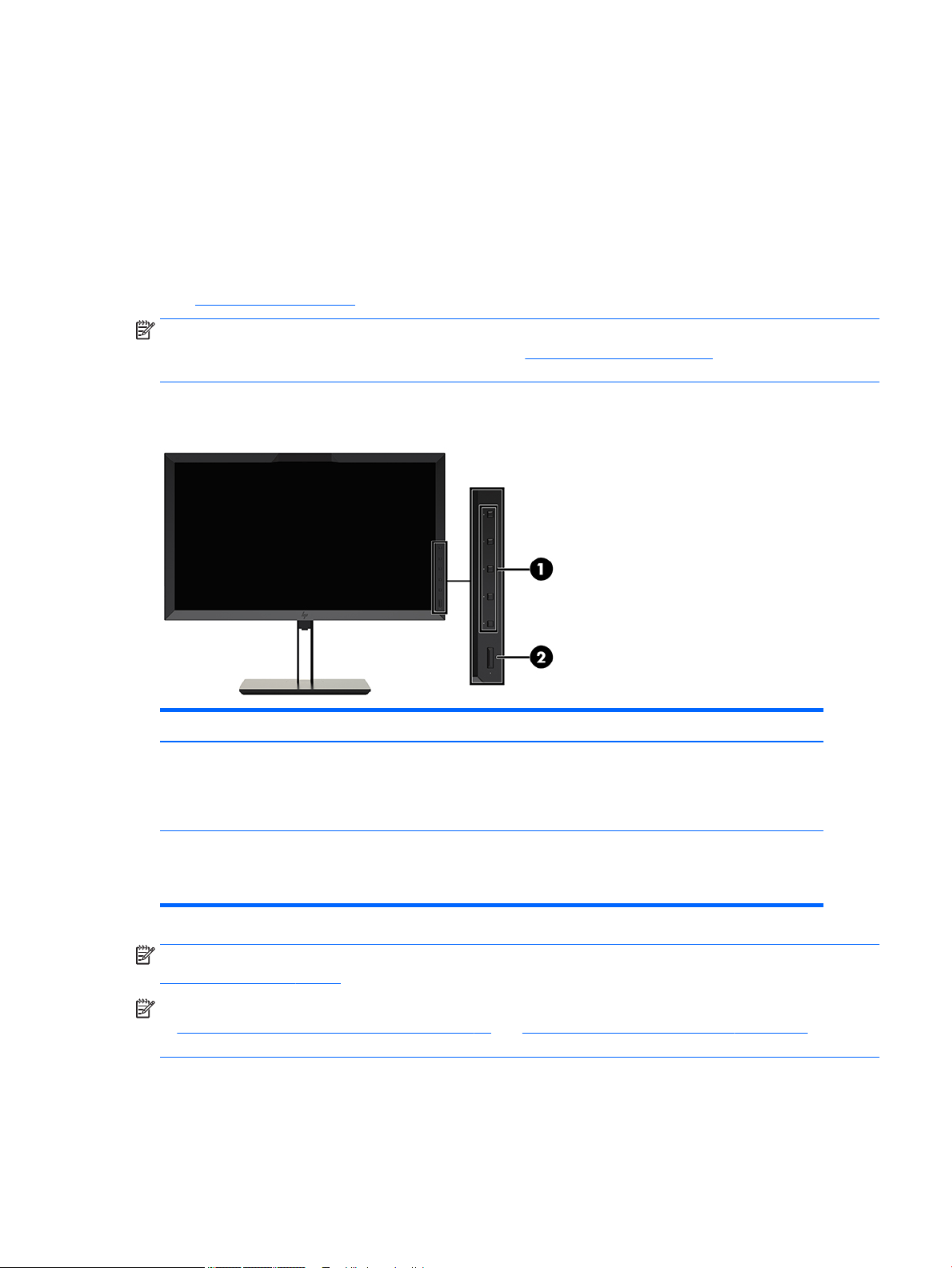
Front panel controls
Control Function
1 Function buttons Use these buttons to navigate through the OSD based on the indicators next to the
buttons that are activated while the OSD is open.
NOTE: To activate the Function buttons, press any of the buttons so that the button
labels appear on the right side of the screen and the button LEDs are lit.
2 Power button Turns the display on or o.
NOTE: Be sure the master power switch on the rear of the display is in the ON position
to turn on the display.
NOTE: To view an OSD menu simulator, visit the HP Customer Self Repair Services Media Library at
http://www.hp.com/go/sml.
NOTE: You can adjust the bezel button brightness and change the function of the buttons in the OSD. Refer
to Changing the bezel function buttons on page 37 and Adjusting the bezel button LEDs on page 39 for
more information.
Product features and components 3

Rear and side components
Component Function
1 Master power switch Turns o all power to the display.
NOTE: Putting the switch in the O position yields the lowest
power state for the display when it is not in use.
2 AC power connector Connects the AC power cord to the display.
3 HDMI1 Connects an HDMI cable to the display.
4 HDMI2 Connects an HDMI cable to the display.
5 DisplayPort 1 Connects a DisplayPort cable to the display.
6 DisplayPort 2 Connects a DisplayPort cable to the display.
7 Analog audio out Connects headphones to the display.
8 KVM keyboard port Connects a keyboard to the display.
9 RJ-45 connector Connects a network cable to the display.
10 DreamColor USB ports (2) Connect a measurement instrument or a USB ash drive for
color calibration or rmware update.
11 USB Type-C upstream port
(for host connections)
12 USB 3.0 upstream port Connects the USB hub cable to the display's USB hub connector
Connects a host device with a Type-C connector.
and to a host USB port/hub.
13 USB 3.0 downstream ports
14 USB 3.0 downstream ports
4 Chapter 1 Getting Started
Connect optional USB devices to the display.
(2)
Connect optional USB devices to the display.
(side panel) (2)
Setting up the display
Use caution when setting up the display
CAUTION: To prevent damage to the display, do not touch the surface of the LCD panel. Pressure on the
panel may cause nonuniformity of color or disorientation of the liquid crystals. If this occurs the screen will
not recover to its normal condition.
To prevent damage to the display, be careful not to put pressure on the colorimeter area (top center of bezel)
when transporting the display.
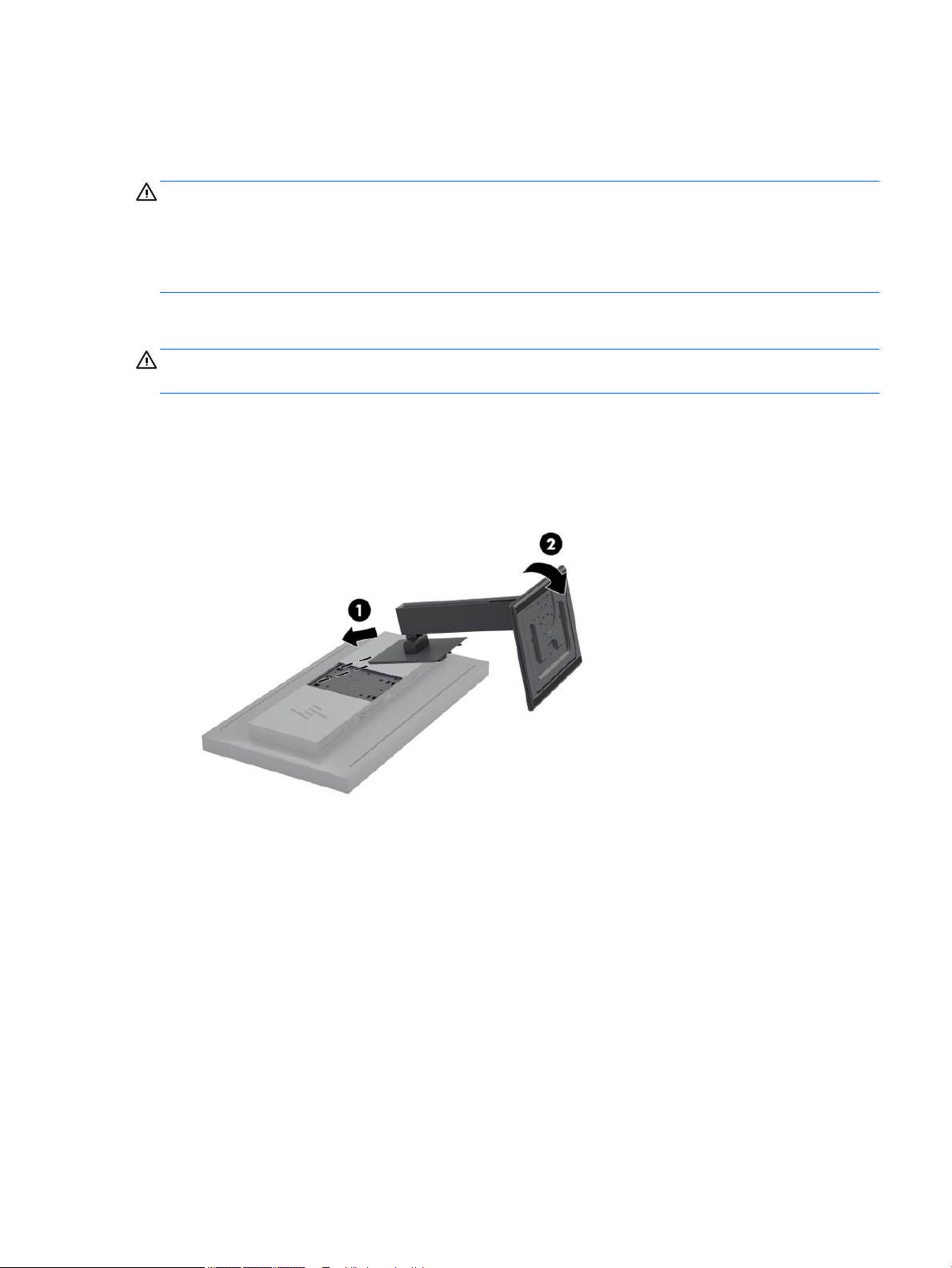
Installing the display stand
CAUTION: Do not touch the surface of the LCD panel. Pressure on the panel may cause non-uniformity of
color or disorientation of the liquid crystals. If this occurs the screen will not recover to its normal condition.
The display oers easy mounting and unmounting of the display panel. To mount the panel onto the stand:
1. Lay the display panel facedown on a at surface covered by a clean, dry cloth.
2. Slide the top of the stand (1) under the upper lip of the recess in the back of the panel.
3. Lower the bottom of the stand's mounting plate (2) into the recess until it snaps into place.
Setting up the display 5
Mounting the display
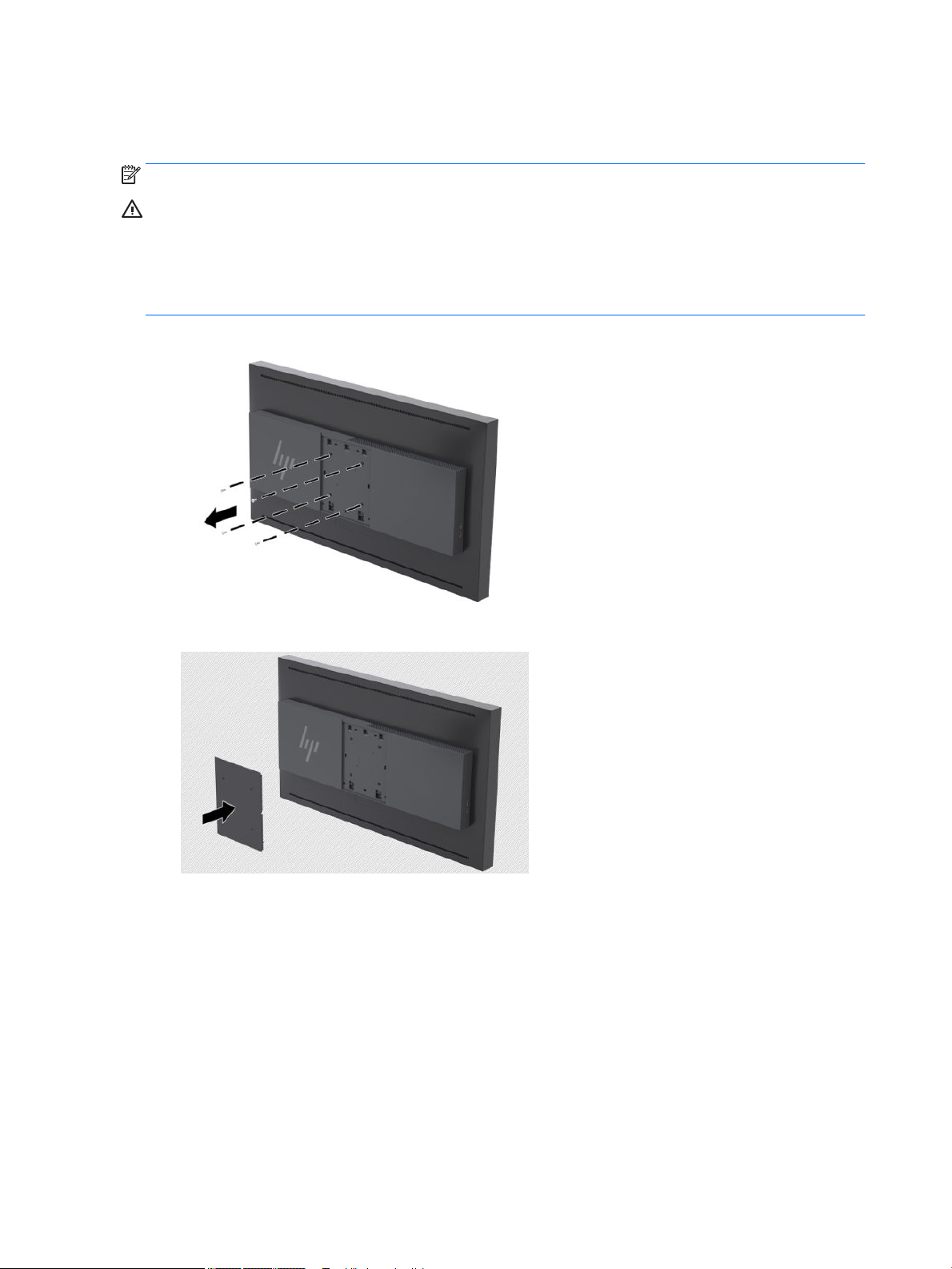
The display head can optionally be attached to a wall, swing arm, or other mounting xture.
NOTE: This apparatus is intended to be supported by UL or CSA Listed wall-mount bracket.
CAUTION: This display supports the VESA industry-standard 100 mm mounting holes. To attach a third-
party mounting solution to the display, four 4 mm, 0.7 pitch, and 15 mm-long screws are required. Longer
screws must not be used because they may damage the display. It is important to verify that the
manufacturer’s mounting solution is compliant with the VESA standard and is rated to support the weight of
the display panel. For best performance, it is important to use the power and video cables provided with the
display.
1. Remove the four screws from the VESA holes located on the rear of the display head.
2. Install the included back plate cover over the mounting screws on the rear of the display.
6 Chapter 1 Getting Started
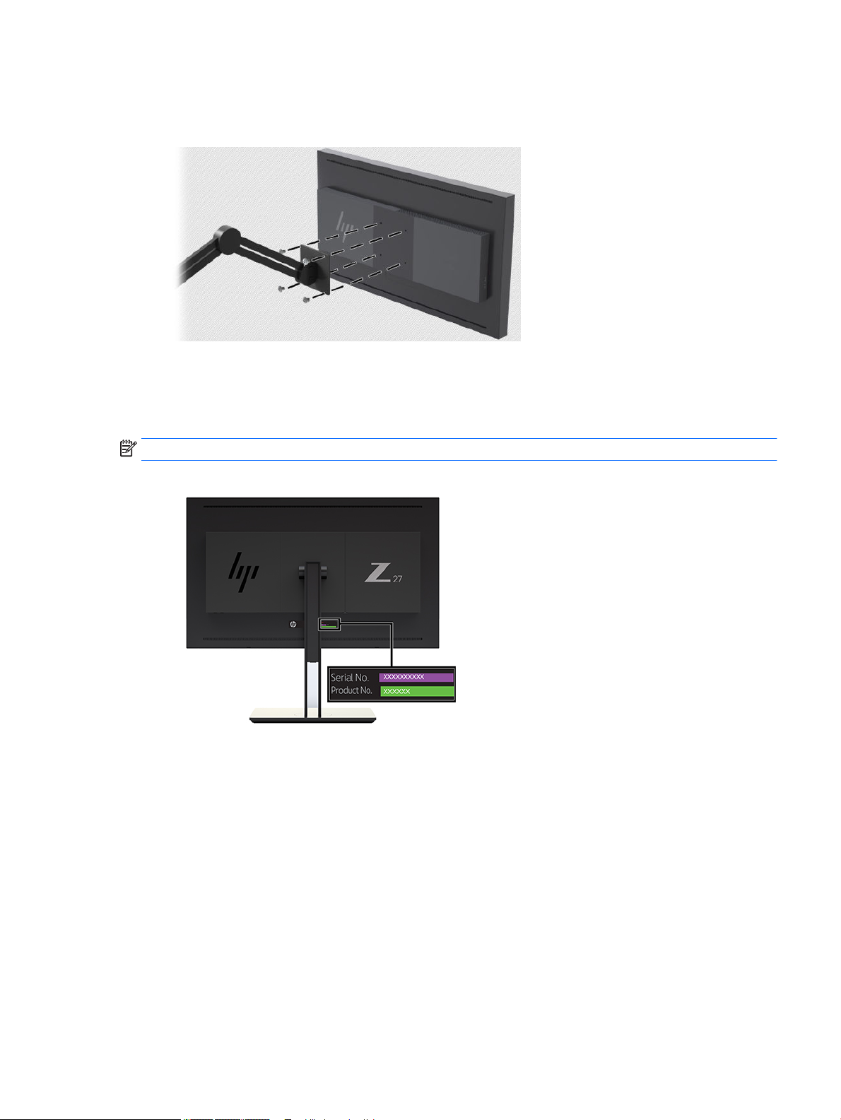
3. To mount the display head directly to a mounting xture, use the four screws removed from the VESA
holes on rear of the display head and install them to attach the mounting device to the rear of the
display.
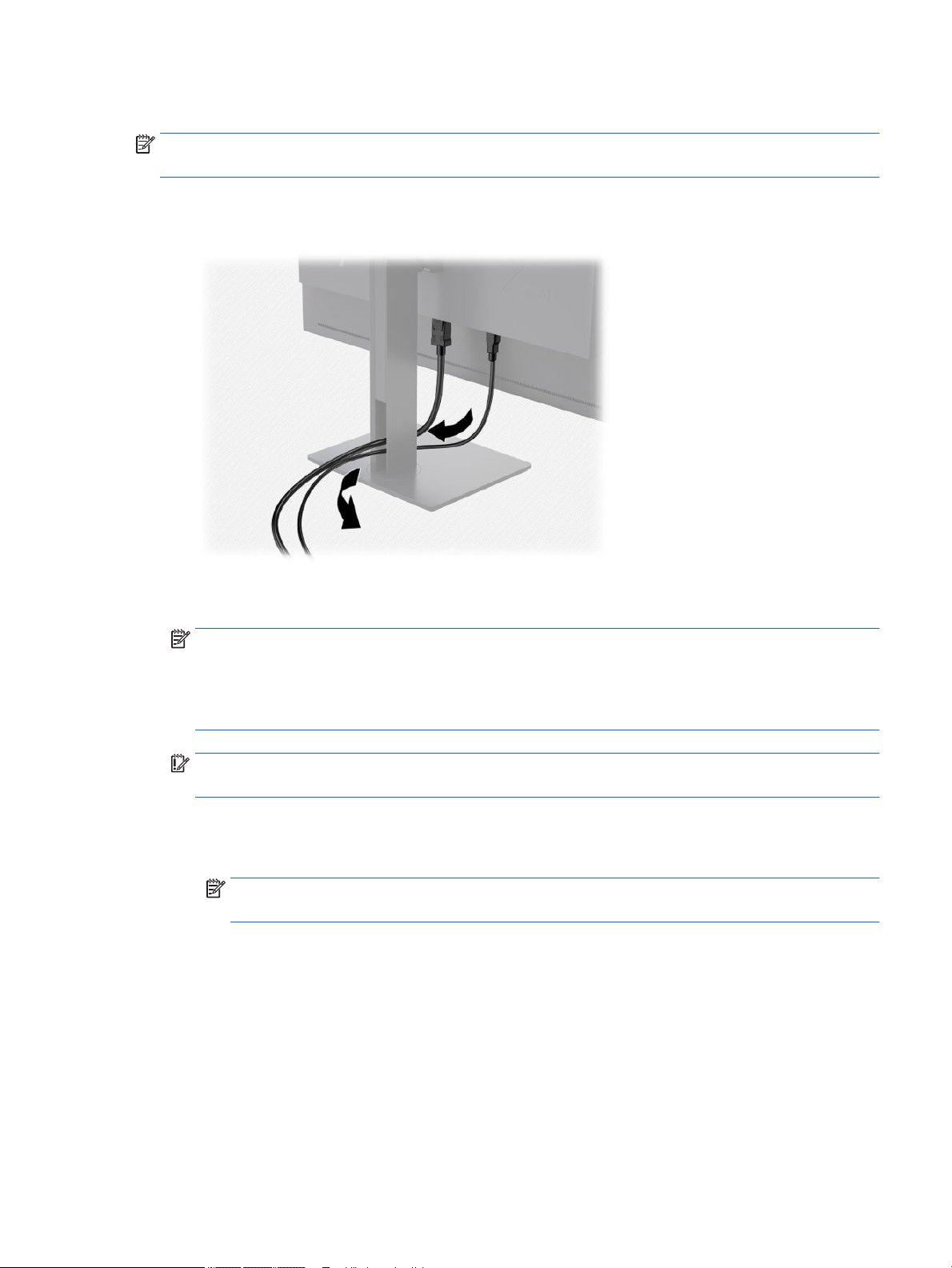
Locating the serial number and product number
The serial number and product number are located on a label on the rear panel of the display head. You may
need these numbers when contacting HP about the display.
NOTE: You may need to partially pivot the display head to read the label.
Setting up the display 7

Attaching an optional device to the rear of the display
A bracket with four 40mm×40mm VESA standard mounting holes is available that allows you to mount a
device such as an SDI or video over ip converter to the rear of the display.
▲ Place the bracket against the rear of the display with the screw holes aligned, and then install the
screws.
Installing a security cable
You can secure the display to a xed object with an optional security cable available from HP.
8 Chapter 1 Getting Started
Connecting the cables
NOTE: The display ships with select cables. Not all cables shown in this section are included with the
display.
1. Place the display in a convenient, well-ventilated location near the computer.
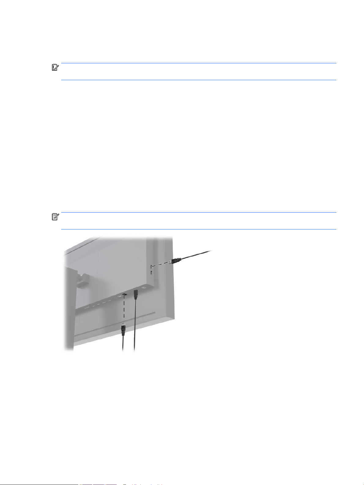
2. Before connecting the cables, route the cables through the cable routing hole in the center of the stand.
3. Depending on your conguration, connect either the DisplayPort, HDMI, or USB Type-C cable between
the computer and the display.
NOTE: The video mode is determined by the video cable used. The display will automatically
determine which inputs have valid video signals. The inputs can be selected through the On-Screen
Display (OSD) feature by pressing one of the front bezel buttons to activate the buttons, and then press
the Open Menu button to open the OSD. In the OSD, select Video Input and choose the desired input
source.
IMPORTANT: USB-C input must be manually selected for a video input. Once USB-C is selected for the
video input, auto-scanning of the HDMI and DisplayPort inputs is disabled.
● For DisplayPort digital operation, connect the DisplayPort signal cable to the DisplayPort
connector on the rear of the display and the other end to the DisplayPort connector on the
computer (cable provided).
NOTE: There are two DisplayPort connections on the rear of the display that allow you to connect
two workstations to the display.
Setting up the display 9

● For HDMI digital operation, connect the HDMI signal cable to the HDMI port on the rear of the
display and the other end to the HDMI port on the computer (cable provided).
NOTE: There are two HDMI ports on the rear of the display allowing you to connect two video
devices to the display.
10 Chapter 1 Getting Started
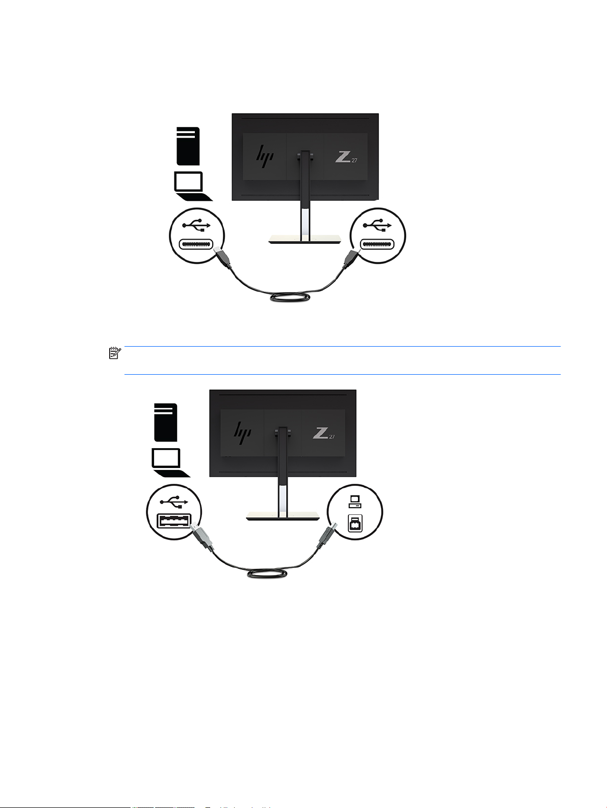
● For USB Type-C digital operation, connect the USB Type-C cable to the USB Type-C connector on
the rear of the display and the other end to the USB Type-C connector on the computer (cable
provided).
4. Connect one end of the provided USB cable to the USB downstream port on the rear panel of the
computer, and the other end to the upstream USB connector on the display.
NOTE: The display supports USB 3.0. For optimal performance, connect the USB cable to a USB 3.0
port on the computer, if available.
Setting up the display 11
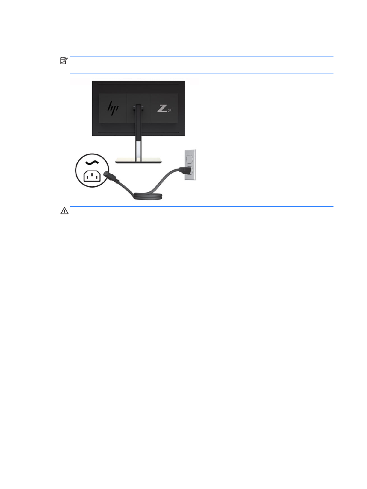
5. Connect one end of the power cord to the AC power connector on the back of the display, and the other
end to an AC outlet.
NOTE: The master power switch on the rear of the display must be in the On position before pressing
the power button on the front of the display.
WARNING! To reduce the risk of electric shock or damage to the equipment:
Plug the power cord into an AC outlet that is easily accessible at all times.
Disconnect power from the computer by unplugging the power cord from the AC outlet.
If provided with a 3-pin attachment plug on the power cord, plug the cord into a grounded (earthed) 3pin outlet. Do not disable the power cord grounding pin, for example, by attaching a 2-pin adapter. The
grounding pin is an important safety feature.
For your safety, do not place anything on power cords or cables. Arrange them so that no one may
accidentally step on or trip over them. Do not pull on a cord or cable. When unplugging from the AC
outlet, grasp the cord by the plug.
12 Chapter 1 Getting Started
Adjusting the display
1. Tilt the display's panel forward or backward to set it to a comfortable angle. Ideally the panel surface
should be perpendicular to your eyes.
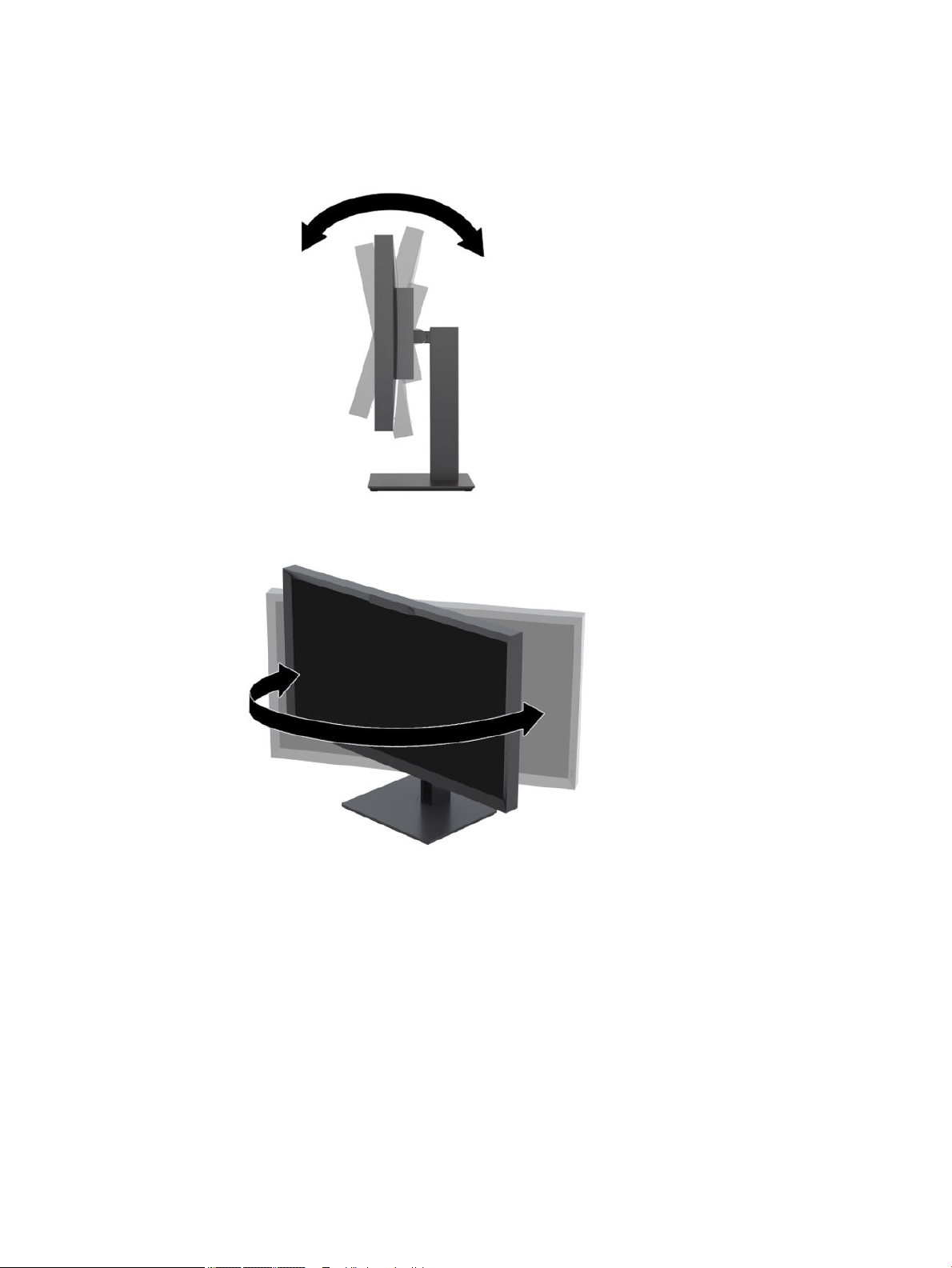
2. Swivel the display to the left or right for the best viewing angle.
Setting up the display 13
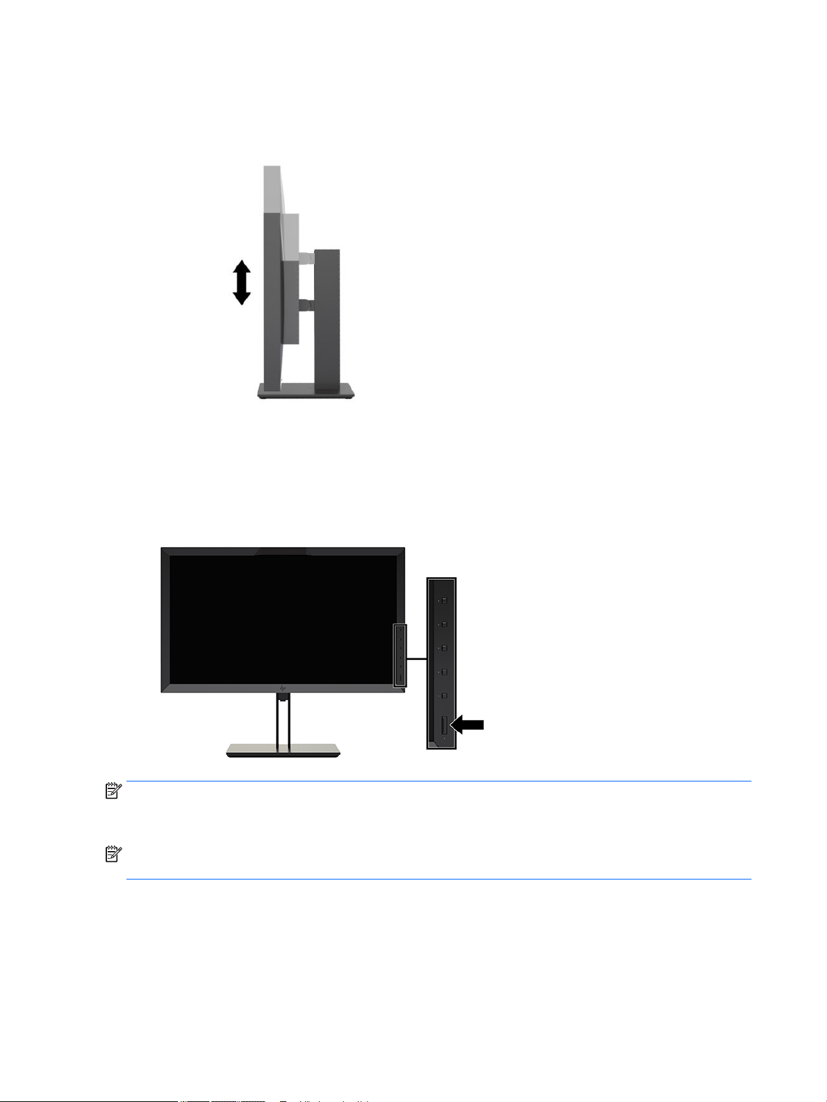
3. Adjust the display’s height to a comfortable position for your individual workstation. The display’s top
bezel edge should not exceed a height that is parallel to your eye height. A display that is positioned low
and reclined may be more comfortable for users with corrective lenses. The display should be
repositioned as you adjust your working posture throughout the work day.
Turning on the display
1. Set the master power switch on the rear of the display to the On position.
2. Press the power button on the computer to turn it on.
3. Press the power button on the front of the display to turn it on.
NOTE: The rst time the display is turned on from the master power switch it may take up to 30 seconds
before the display responds to the front power button. This is normal and is due to the booting of internal
systems.
NOTE: If pressing the power button has no eect, the Power Button Lockout feature may be enabled. To
disable this feature, press and hold the display power button for 10 seconds.
When the display is powered on, a status message is displayed for ve seconds. The message shows which
input is the current active signal, the status of the auto-switch source setting (On or O; factory default is
On), the default source signal (factory default is DisplayPort), the current preset display resolution, and the
recommended preset display resolution.
The display automatically scans the signal inputs for an active input and uses that input for the display. If two
or more inputs are active, the display will indicate the default input source. If the default source is not one of
14 Chapter 1 Getting Started
the active inputs, then the display will indicate the highest ranking priority input. You can select the input
source in the OSD. Press one of the front bezel buttons to activate the buttons, and then press the Open Menu
button to open the OSD. In the OSD select Video Input and choose the desired input source.
IMPORTANT: USB-C input must be manually selected for a video input. Once USB-C is selected for the video
input, auto-scanning of the HDMI and DisplayPort inputs is disabled.
HP watermark and image retention policy
The IPS display models are designed with IPS (In-Plane Switching) display technology which provides ultrawide viewing angles and advanced image quality. IPS displays are suitable for a wide variety of advanced
image quality applications. This panel technology, however, is not suitable for applications that exhibit static,
stationary or
applications may include camera surveillance, video games, marketing logos, and templates that are
displayed on the screen for a prolonged period of time. Static images may cause image retention damage that
could look like stains or watermarks on the display's screen.
Displays in use for 24 hours per day that result in image retention damage are not covered under the HP
warranty. To avoid image retention damage, always turn o the display when it is not in use or use the power
management setting, if supported on your system, to turn o the display when the system is idle.
xed images for long periods of time without the use of screen savers. These types of
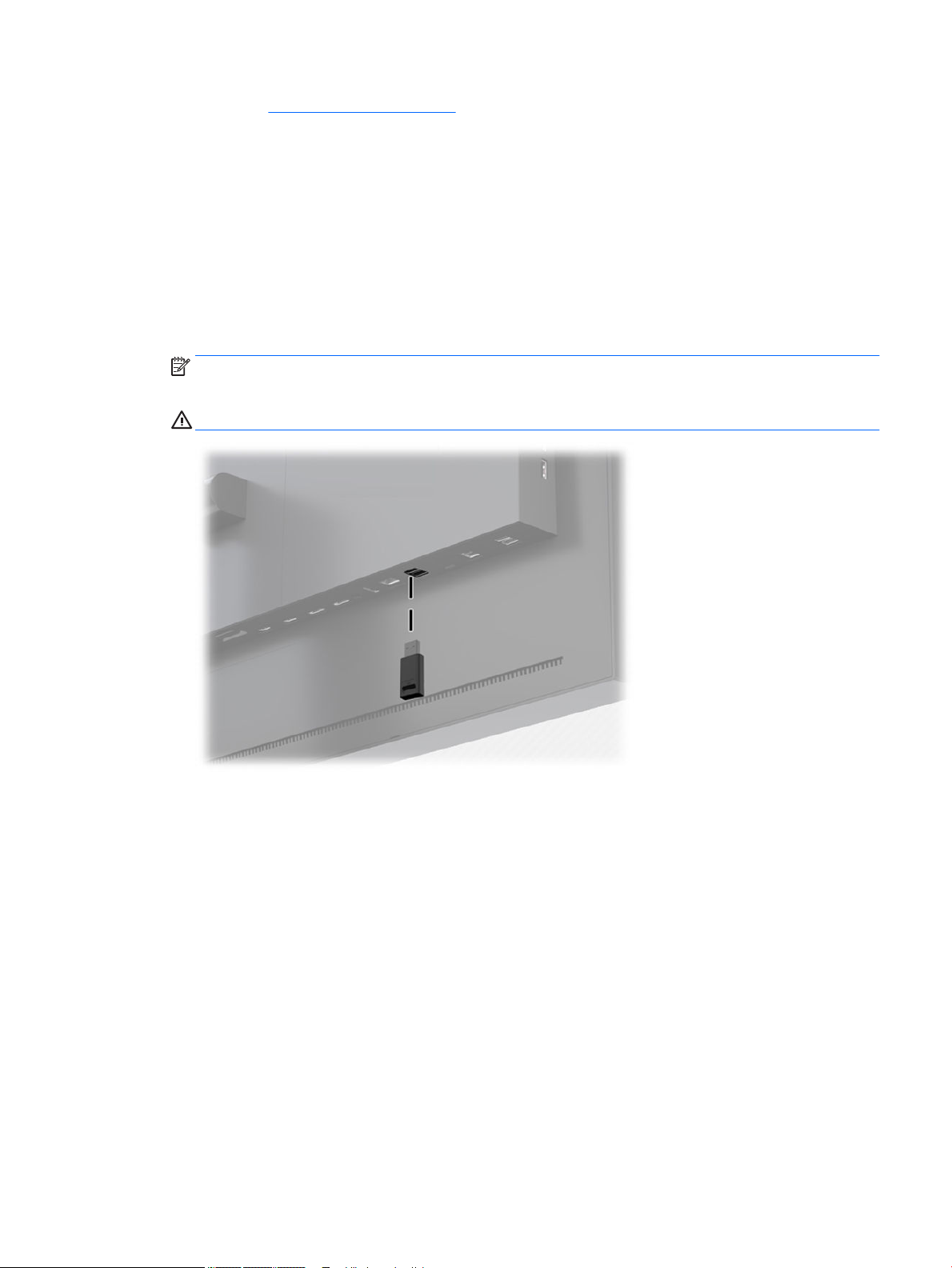
Connecting USB devices
There are four downstream USB ports on the display (two on the rear and two on the side).
NOTE: You must connect the USB hub cable (USB Type-B or USB Type-C) from the display to the computer to
enable the USB ports on the display.
Setting up the display 15
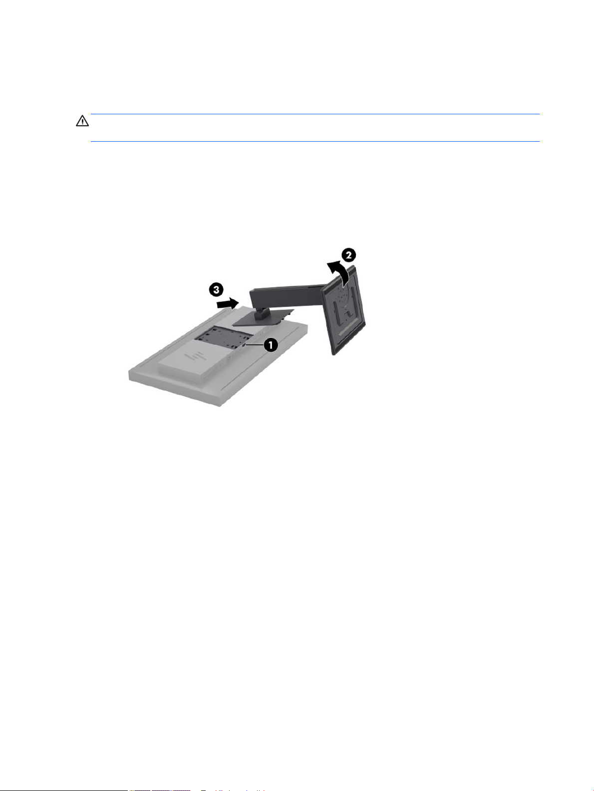
Removing the display stand
You can remove the display head from the stand to install the panel on a wall, a swing arm, or other mounting
xture.
CAUTION: Before beginning to disassemble the display, be sure it is turned o and the power, signal, and
network cables are all disconnected. Also disconnect all USB cables connected to the display.
1. Disconnect and remove all cables from the display.
2. Lay the display facedown on a at surface covered by a clean, dry cloth.
3. Press down on the latch near the bottom center of the display to unlock the stand (1).
4. Swing the bottom of the stand up until the mounting plate clears the recess in the panel (2).
5. Slide the stand out of the recess (3).
16 Chapter 1 Getting Started

2 Using the display
Software and utilities
The disc that comes with the display contains les you can install on the computer.
● an .INF (Information) le
● ICM (Image Color Matching) les (one for each calibrated color space)
● USB Software Development Kit (SDK) for Linux, Windows, and Mac
● sample StudioCal XML scripts
NOTE: The items listed above can be downloaded from the HP display support Web site. For more
information, go to Downloading from the Internet on page 18.
The information le
The .INF le denes display resources used by Microsoft Windows® operating systems to ensure display
compatibility with the computer’s graphics adapter.
This display is Microsoft Windows Plug and Play-compatible. It works correctly without installing the .INF le.
Plug and Play compatibility requires that the computer’s graphic card is VESA DDC2-compliant and that the
display connects directly to the graphics card.
The image color matching les
The ICM les are data les that describe the colorimetry of the display. In the case of calibrated displays, they
describe the colorimetry of a given color preset. This information includes the preset's calibrated color gamut,
grayscale response, and white point. These les are used by the operating system's color management
engine—as well as the color management engine built into specialized photography, video, and graphic arts
applications—to ensure that colors on-screen are rendered correctly and will be displayed accurately when
viewed on the display. While not all programs support the use of these les, HP strongly recommends that
you always select or enable the ICM le matching the active color preset to ensure the best image
reproduction.
NOTE: The ICM color prole is written in accordance with the International Color Consortium (ICC) Prole
Format specication.
Software and utilities 17

Installing the .INF and .ICM les
You can install the .INF and .ICM les from the disc or download them.
Installing from the disc
To install the .INF and .ICM les on the computer from the disc:
1. Insert the disc in the computer optical drive. The disc menu is displayed.
2. View the HP Display Software Information le.
3. Select Install Display Driver Software.
4. Follow the on-screen instructions.
NOTE: While an .INF le is Windows specic, if you are running macOS or Linux, you may want to install
the .ICM les to ensure on-screen color accuracy. These les can be manually copied to your computer. Refer
to your host operating system guide for information on where to install these les.
Downloading from the Internet
To download the latest version of .INF and .ICM les from the HP displays support Web site:
1. Go to http://www.hp.com/support.
2. Enter the name of your HP product or product number in the Search all support box, and then click the
search icon.
3. Select from the menu options shown to get your drivers, software, and rmware.
4. Download the software by following the instructions.
Updating the rmware
HP recommends that you check for updated display rmware and install newer rmware if available.
NOTE: By default, the display’s internal processor – which is required for rmware updating – is disabled.
You must enable the processor before you can update the display rmware. In the OSD select Management >
Internal processor and choose Enable to turn the processor on. If turning on just before attempting to
update the rmware, wait approximately one minute for the internal processor to fully boot.
To update the rmware with USB:
1. Check your current rmware version.
a. Press any Function button on the front bezel.
b. Press the Open Menu button to open the OSD.
c. Select Information to view the current rmware version.
TIP: A bezel Function button shortcut, Display Info, is provided on the fourth bezel button in the
display’s factory conguration. You can access this information page using this shortcut, unless the
bezel button has been reassigned. This information page also indicates whether the internal
processor is on or o.
2. Find the latest rmware on the Web.
18 Chapter 2 Using the display
a. Go to http://www.hp.com/support.
b. Enter the name of your HP product or product number in the Search all support box, and then click
the search icon.
c. Select from the menu options shown to get your rmware.
d. Check the latest rmware revisions listed for the display to see if it is a newer version than what is
currently installed.
e. Download the rmware onto a USB ash drive. The following USB drive formats are supported: FAT,
FAT32, NTFS.
3. Insert the USB ash drive with the latest rmware into one of the DreamColor USB ports and follow the
on-screen instructions to install the rmware.
NOTE: The rmware is distributed as a compressed, signed rar le. Do not decompress the le before
installing.
CAUTION: Do not turn o the display during the rmware update.
Updating the rmware 19

Selecting a color space preset
The display provides factory calibrated color space presets, suitable for a wide variety of color-critical
workows including visual eects, animation, on-set/dailies viewing, professional photography, product
design, print/pre-press, graphic arts, and many others. Seven industry standard color spaces are provided
along with the display’s native color gamut. The following table provides information on the eight provided
standard color spaces.
Preset
number
0 DCI P3 D65 0.496, 0.526 0.099, 0.578 0.175, 0.158 D65 2.4
1 BT.709 0.451, 0.523 0.125, 0.563 0.175, 0.158 D65 BT.1886
2 BT.2020 0.557, 0.516 0.056, 0.587 0.159, 0.126 D65 BT.1886
3 sRGB D65 0.451, 0.523 0.125, 0.563 0.175, 0.158 D65 sRGB
4 sRGB D50 0.451, 0.523 0.125, 0.563 0.175, 0.158 D50 sRGB 250 cd/m²
5 Adobe RGB D65 0.451, 0.523 0.076, 0.576 0.175, 0.158 D65 2.2
6 Adobe RGB D50 0.451, 0.523 0.076, 0.576 0.175, 0.158 D50 2.2
7 Native Panel Panel Panel D65 2.2
Preset name Red primary
(u’v’)
Green
primary (u’v’)
Blue primary
(u’v’)
White
point
Default gamma or
EOTF
Default
luminance
100 cd/m
100 cd/m
100 cd/m
250 cd/m
250 cd/m
250 cd/m
250 cd/m
2
2
2
2
2
2
2
NOTE: The factory DCI-P3 preset has a D65 white point, a 100 cd/m² luminance and a Power 2.4 gamma.
This diers from the DCI-P3 conguration typically found in cinema projectors (P3 white point, a 48 cd/m²
luminance and a Power 2.6 gamma). This is because consultation with visual eect and animation studios
determined that the D65/100/2.4 conguration was better suited to the typical artist work environment than
the cinema projector conguration.
To select a color space preset:
1. Press any Function button on the front bezel.
2. Press the Open Menu button to open the OSD.
3. Select Color settings to display the color space conguration screen.
4. Use the Up/Down buttons to navigate to the desired color space, and then press the Select button to
activate it.
Adjusting luminance
Though each preset is calibrated to a specic luminance level, the luminance can be adjusted post-calibration.
The luminance range for all calibrated color space presets can be adjusted from 48–250 cd/m2.
NOTE: Due to the way LEDs respond to voltage, the further you adjust luminance away from the calibrated
value, the less accurate the luminance value reported by the OSD will be. As you move away from the
calibrated value, the colorimetry of the white point will shift. HP recommends that you calibrate the display to
the desired working luminance. For more information about calibration, see Display calibration on page 57.
To adjust luminance:
1. Press any Function button on the front bezel.
2. Press the Open Menu button to open the OSD.
20 Chapter 2 Using the display

3. Select Color settings to display the color space conguration screen.
4. Use the Up/Down buttons to navigate to the Adjust luminance option, and then press the Select button
to activate it.
5. Use the Increase/Decrease buttons to adjust the luminance to the desired level.
NOTE: The Adjust luminance option displays the current luminance value to the right of the menu option.
Understanding image adjustment options
Several special image adjustment options are designed to t specic workows in the media and
entertainment industry. The following section describes these functions from the perspective of their
application in these workows.
Video signal adjustments
Downstream RGB adjust
In some cases it may be necessary post-calibration to tweak the setup (black) or gain (white) of one or more
of the RGB channels in order to visually match another display or projector. These adjustments are positioned
downstream of (i.e., after) the color management processing block in the display hardware. These
adjustments provide 10-bit precision.
To adjust setup and gain RGB:
1. Press any Function button on the front bezel.
2. Press the Open Menu button to open the OSD.
3. Select Color settings > Downstream RGB adjust.
4. Use the adjustment settings to adjust Setup and Gain until you achieve the desired color match with the
other display device.
Use video levels (64–960)
This option is designed to support the accurate display of “video legal” signals that include footroom below
black and headroom above white. These types of signals are typically encountered when working with video
signals that conform to the complete ITU-R BT.709 standard. This standard allows for excursions beyond
black and white, rather than treating black and white as absolutes.
These signals are typically encountered in the following situations:
● Viewing the HDMI or HD-SDI output from a video capture and playback card such as an AJA Kona or
Blackmagic Design DeckLink
● Viewing an image in the Composer/Edit/Preview window in a non-linear video editing program
● Viewing the output of a consumer Blu-Ray/DVD player
In all of these situations the video signal usually includes the BT.709 headroom and footroom. Without this
option enabled when viewed in a display, the blacks and shadows are lighter, the whites are darker, and colors
have less saturation than the signal actually contains.
When this option is enabled the blacks will be clipped at the 10-bit value of 64 and the whites at the 10-bit
value of 960 (for 8-bit, the clipping will occur at the values of 16 and 235). The signal is then remapped to
display the signal in the correct visual range.
Understanding image adjustment options 21

If you are unsure whether you are using source material with head and footroom, check the application
settings or check with someone who can tell you how the source material was captured or rendered. Note
that you may need to adjust the lightness of your editing application interface after enabling this setting.
To use video levels:
1. Press any Function button on the front bezel.
2. Press the Open Menu button to open the OSD.
3. Select Image adjustment to display the adjustment options screen.
4. Use the Up/Down buttons to navigate to the Video legal (64–960) option then press the Select button
to select it. The option will be selected when it is active.
Overscan the frame
By default the display shows all pixels in the image, when screening video dailies or an edit revision it may be
desirable to view the image in an overscanned mode, similar to how it is viewed on a consumer digital
television. The Overscan Frame option will enlarge the image by 5% so that only that portion of the frame
within the Action Safe region is displayed. Action Safe is traditionally dened as an area that begins 5% inside
the edge of the frame.
To use the Overscan Frame mode:
1. Press any Function button on the front bezel.
2. Press the Open Menu button to open the OSD.
3. Select Image adjustment to display the adjustment options screen.
4. Use the Up/Down buttons to navigate to the Overscan frame by 5% option then press the Select button
to select it. The option will be selected when it is active.
Show only the blue channel
The human is least-sensitive to changes in blue, most compression and encoding algorithms assign the least
amount of bandwidth to the blue channel. Because of this, compression/encoding errors are most-easily seen
when viewing the blue channel. The display allows the user to view just the blue channel, temporarily turning
the red and green channels o, so that the image can be inspected for these errors.
To view only the blue channel:
1. Press any Function button on the front bezel.
2. Press the Open Menu button to open the OSD.
3. Select Image adjustment to display the adjustment options screen.
4. Use the Up/Down buttons to navigate to the Blue channel only option then press the Select button to
select it. The option will be selected when it is active.
Using the aspect ratio management options
The display includes a number of special aspect ratio management options that go far beyond what is
typically found in a display. The following section focuses on how these options are integrated into specic
workows.
The “Fill To” options
These options determine how the source input is displayed on-screen if its resolution is dierent from the
display’s native resolution of 2560×1440.
22 Chapter 2 Using the display
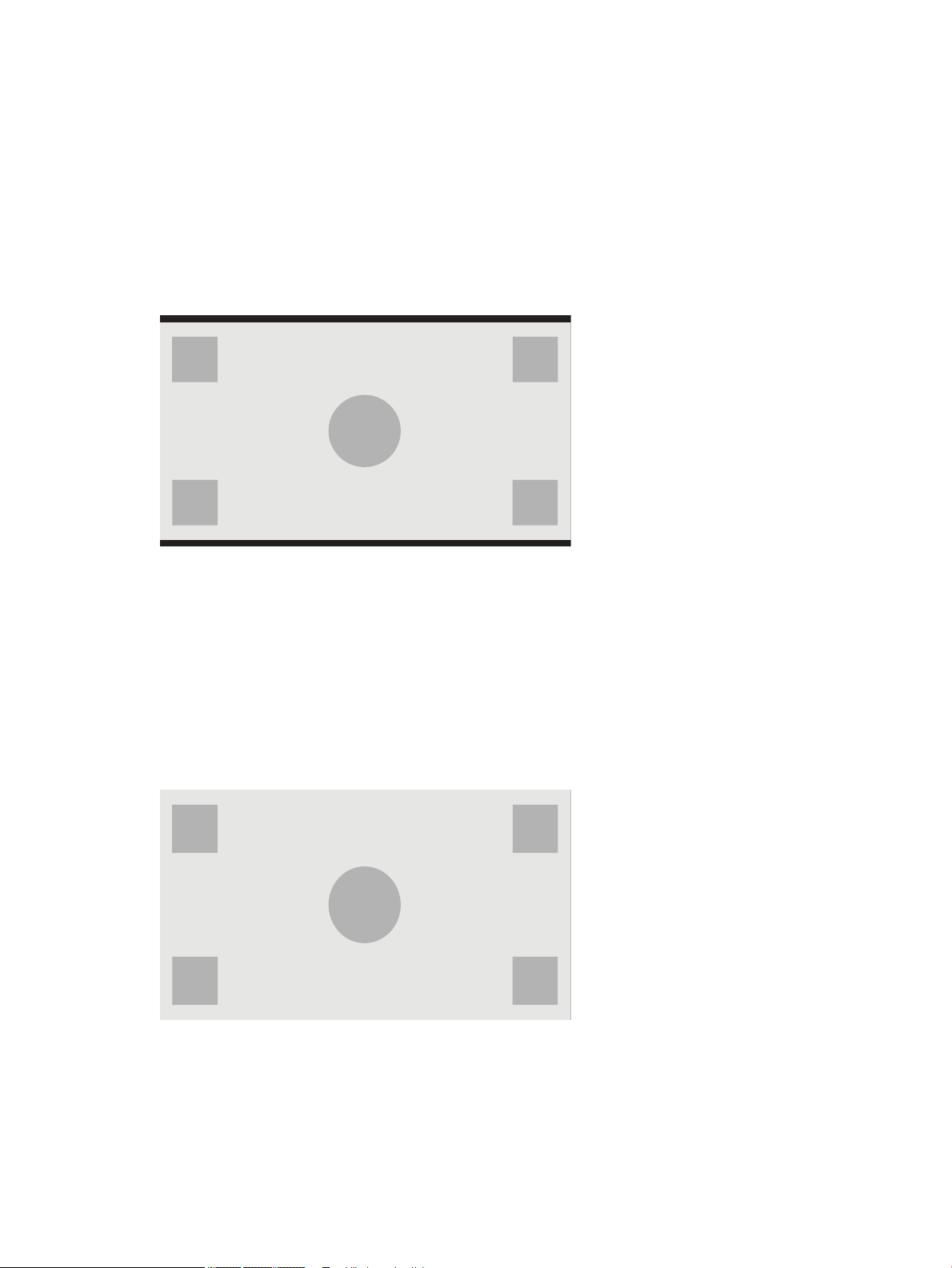
Fill to source aspect ratio (proportional)
This option maintains the aspect ratio of the source input, making the image as large as possible, centering it
in the display, and using 0% black to ll the unused areas of the screen. For example, a source input that is
narrower than 16×9 will be displayed at full height with black bars to the left and right of the source image,
and a source input that is wider than 16×9 will be the displayed at full width with black bars above and below
the source image.
Fill to Source Aspect Ratio is the default and is the option most suitable to the majority of workows.
The following illustration shows a the visual result when a 2048×1080 source input is displayed on the
display with the Fill to source aspect ratio (proportional) option enabled.
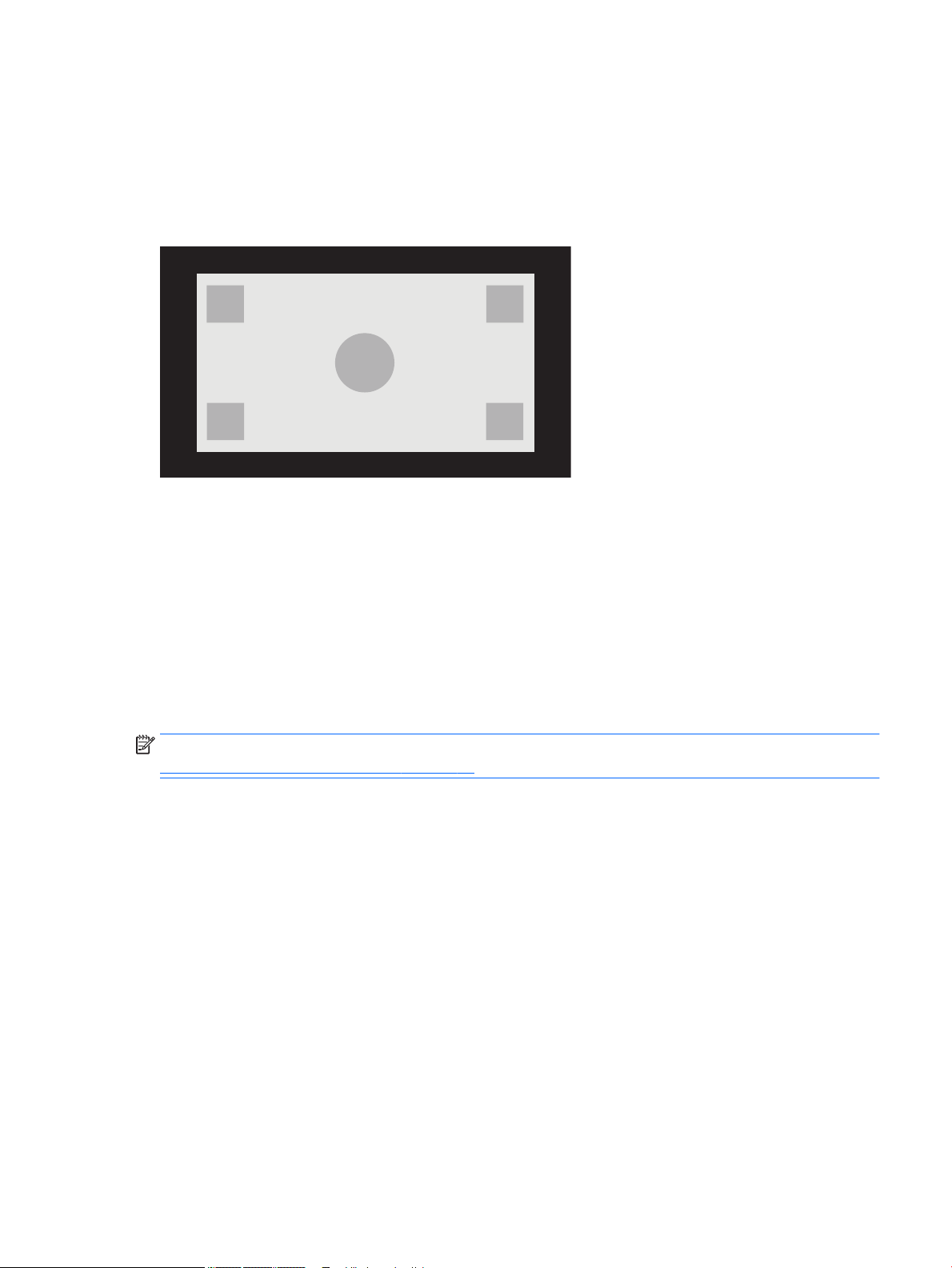
Fill to entire screen (non-proportional)
This option distorts source aspect ratios other than 16×9 to force them to t within the display’s 16×9 aspect
ratio. The resulting image will take up the entire display and will either be stretched horizontally (for narrower
aspect ratios) or vertically (for wider aspect ratios).
Use Fill to Entire Screen if the source aspect ratio is irrelevant and you want the entire screen to be lled,
regardless of the distortion that may be caused.
The following illustration shows the visual result when a 2048×1080 source input is displayed on the display
with the Fill to entire screen (non-proportional) option enabled. Notice that, as compared to the previous
illustration, the circle and squares are stretched horizontally so the image lls the entire 16:9 aspect ratio.
Fill to screen width (proportional)
This option is for specic workows with source video that is narrower than the display’s native 16×9 aspect
ratio. In some lm workows it is desired to render the animation or visual eects at an Academy or other
taller aspect ratio and perform a “center extraction” for widescreen delivery. If enabled, this option will resize
the source image so that the width matches the display width. Then the source image is centered vertically
Understanding image adjustment options 23

and the top and bottom of the image are cropped o, leaving a 16×9 “center extraction” of the Academy
frame. The proportions of the source image are maintained.
The Fill to Screen Width option should be used when vertical center extractions are desired as part of the
dailies or review screening process.
The following illustration shows the visual result when a 1024×768 source input is displayed on the display
with the Fill to screen width ratio (proportional) option enabled. Note that, as compared to the previous
illustration, the area above and below the outside squares has been cropped out and the image resized to
take up the entire 16:9 frame.
Fill to screen height (proportional)
This option is for specic workows with source video that is wider than the display’s native 16×9 aspect
ratio. In some lm workows it is desired to see a 17×9 horizontal extraction of a wider source aspect ratio. If
enabled, this option will resize the source image so that the height matches the display height. Then the
source image is centered horizontally and the left and right of the image are cropped o, leaving a 16×9
“center extraction” of the wider frame. The proportions of the source image are maintained.
The Fill to Screen Height option should be used when horizontal center extractions are desired as part of the
dailies or review screening process.
The following illustration shows a 2048×858 source input image and the visual result when that source input
is displayed on the display with the Fill to screen height ratio (proportional) option enabled. Notice that the
right and left edges of the frame have been cropped out and the image resized to take up the entire 16:9
frame.
24 Chapter 2 Using the display
Pixel-for-pixel
This option is for source video that has a lower resolution than the display’s native resolution of 2560×1440
and you wish to view the image without any scaling applied. If enabled, this option will display the source
input in its native size and ll the remainder of the frame with 0% black.
The following illustration shows the visual result when a 2048×1080 source input is displayed on the display
with the pixel-for-pixel option enabled.
Using the “Fill To” options
To change the way the source video is displayed on-screen:
1. Press any Function button on the front bezel.
2. Press the Open Menu button to open the OSD.
3. Select Image adjustment to display the adjustment options screen.
4. Select Image scaling to show the display options.
5. Use the Up/Down buttons to navigate to the desired open option. Then press the Select button to select
it.
NOTE: The Image scaling menu can be reassigned to a bezel Function button for easy access. Refer to
Changing the bezel function buttons on page 37 for instructions on assigning the bezel Function button.
Understanding image adjustment options 25

Digital cinema aspect ratio masking
The display supports aspect ratio masking for the two standard aspect ratios, 1.85:1 and 2.39:1, within the
DCI image container. When digital cinema masking is enabled, the source signal is masked to only show the
pixels within the chosen aspect ratio. The following table lists the active pixels that will be displayed for each
image container and aspect ratio.
DCI Container Size Aspect Ratio Horizontal Active Pixels Vertical Active Pixels
2048 × 1080 1.85:1 1998 1080
2048 × 1080 2.39:1 2048 858
Using the digital cinema aspect ratio masking options
All of the digital cinema display options are located in the OSD on the Main menu > Image adjustment >
Digital Cinema Masking page. These options are unavailable and the menu option dimmed unless
2048×1080 is being displayed using the active video input.
To access the digital cinema masking options:
1. Connect a computer or video device to the display that is congured to output a 2048×1080 signal.
2. Press any button on the front bezel.
3. Press the Open Menu button to open the OSD.
4. Select Image adjustment to display the adjustment options screen.
5. Select Digital cinema masking to display the digital cinema options.
The following digital cinema masking options are available.
Show entire DCI container
This is the default option and will show the entire 2048×1080 frame.
Mask to DCI 1.85:1 aspect ratio
This option masks the left- and right-most 25 pixels of the 2048-wide frame. The resultant image is then
displayed as specied using the image scaling options described in the previous section.
The following illustration shows a DCI source cropped to 1.85:1.
26 Chapter 2 Using the display

Mask to DCI 2.39:1 aspect ratio
This option masks the top- and bottom-most 111 pixels of the 2048-wide frame. The resultant image is then
displayed as specied using the image scaling options described in the previous section.
The following illustration shows the a DCI source cropped to 2.39:1.
Show masked region
When this option is enabled, a partially-transparent mask is used instead of an opaque mask. This option is
useful, for example to check the topline in a 2.39:1 aspect ratio and see what information may be available, if
the headroom needs to be adjusted with reframing.
The following illustration shows the a DCI source cropped to 2.39:1 with the Show masked region option
enabled.
Set mask opacity
This option is available when Show masked region is active and allows you to specify the amount of opacity
applied to the cropped region. Adjust as needed to achieve the desired balance between the active and
cropped regions of the frame.
Understanding image adjustment options 27

Working with markers
The display includes a full set of marker overlays that can be used to indicate specic areas or regions of the
frame. Multiple standard markers are included.
Film aspect ratio markers
Markers are provided for the standard theatrical aspect ratios 1.85:1 and 2.39:1. These markers will place a
line at the lm aspect ratio edge of both 17:9 (2048×1080) and 16:9 (2560×1440, 1920×1080, or 1280×720)
source inputs.
In the case of 17:9 source inputs, the lines are positioned at the DCI-dened locations. For 16:9 inputs, the
lines are positioned at the mathematical location of these lm aspect ratios. This means that a 1.85:1 aspect
ratio will use vertical lines for 17:9 source inputs and horizontal lines for 16:9 source inputs.
17:9 source inputs
16:9 source inputs
NOTE: Only one lm aspect ratio marker can be displayed at once. Therefore, if you have the 1.85:1 aspect
ratio marker enabled and you enable the 2.39 aspect ratio marker, the 1.85 aspect ratio marker will be
disabled.
28 Chapter 2 Using the display

16:9 aspect ratio markers
Markers are provided for the 16:9 aspect ratio. These markers support both 17:9 (2048×1080) and 16:9
(2560×1440, 1920×1080, or 1280×720) source inputs.
● 16:9 extraction: shows the 16:9 region within the 17:9 frame. This marker is only available when a 17:9
(4096×2160 or 2048×1080) source input is used.
● 16:9 action safe: shows the action safe area within 16:9 as dened by EBU R19, Revision 1. This area is
dened as a box 3.5% inward from each edge of the image.
● 16:9 title safe: shows the title safe area within 16:9 as dened by EBU R19, Revision 1. This area is
dened as a box 5% inward from each edge of the image.
The following illustration shows the 16:9 safe action and safe title markers displayed on-screen.
Working with markers 29

4:3 aspect ratio markers
Markers are provided for the 4:3 aspect ratio. These markers support both 17:9 (2048×1080) and 16:9
(2560×1440, 1920×1080, or 1280×720) source inputs.
● 4:3 extraction: shows the 4:3 region within the 17:9 or 16:9 frame.
● 4:3 action safe: shows the action safe area within 4:3 as dened by SMPTE RP 218. This area is dened
as a box 5% inward from each edge of the image.
● 16:9 title safe: shows the title safe area within 16:9 as dened by SMPTE RP 218. This area is dened as
a box 10% inward from each edge of the image.
The following illustration shows the 16:9 safe action and safe title markers displayed on-screen.
30 Chapter 2 Using the display

Crosshair markers
Markers are provided to position crosshairs onscreen. These markers support both 17:9 (2048×1080) and
16:9 (2560×1440, 1920×1080, or 1280×720) source inputs.
● Center crosshair: provides a crosshair at the center of the screen. The crosshair is 300 pixels wide and
300 pixels high.
● Thirds crosshair: provides four crosshairs, dividing the screen into thirds horizontally and vertically. The
crosshairs will be properly positioned for both 17:9 and 16:9 source inputs.
The following illustration shows both the center and thirds crosshair markers for a 16:9 source input.
Marker color
Markers can be dened one of seven dierent colors:
● White
● Red
● Green
● Blue
● Cyan
● Magenta
● Yellow
Custom markers
The display provides support for the creating of custom markers using XML as part of the StudioCal XML
schema. See Using the StudioCal XML schema on page 71 for complete information on the StudioCal XML
schema.
Custom markers can include up to 16 lines and each line can have a unique color and line width. (Line widths
up to 10 pixels are supported.)
There are four elements associated with custom markers.
Working with markers 31

Marker element
The StudioCal XML schema allows for the denition of up to ten lines per custom marker. To support this, a
marker parent element is used to enclose the information for each marker. This element contains two tags,
an “entries” tag to specify the number of lines in the custom marker and a “product” tag to dene the display
the markers are designed for.
The “entries” tag supports integer values between 1 and 16. The “product” tag currently supports only two
values, “Z31x” and "Z27x". You should use "Z27x" for markers designed for this display.
IMPORTANT: The Z31x model has a dierent aspect ratio and number of pixels horizontally and vertically
than the Z27x model. If a StudioCal XML le is inserted into the Z27x with the product set to Z31x, an error
will be returned and the markers will not import.
The element should be structured as follows:
<marker entries="INTEGER, 1–16" product="Z27x">
</marker>
Marker info element
The details for each marker line is stored in two elements. Therefore a “marker_info” parent element is used
to enclose the details for each marker line. This element does not include any tags.
The element should be structured as follows:
<marker_info>
</marker_info>
Marker position element
The xy starting and ending positions for each marker line is stored in a single “marker_pos” element. The
element contains the following tags:
● startx: The line’s x axis starting point. Integer values between 1 and 2560 are supported.
● endy: The line’s x axis ending point. Integer values between 1 and 2560 are supported.
● starty: The line’s y axis starting point. Integer values between 1 and 1440 are supported.
● endy: The line’s y axis ending point. Integer values between 1 and 1440 are supported.
The element should be structured as follows:
<marker_pos startx="INTEGER" endx="INTEGER" starty="INTEGER"
endy="INTEGER"/>
Marker style element
The width and color for each line is stored in a single “marker_style” element. The element contains the
following tags:
● width: The line’s width. Integer values between 1 and 10 are supported.
● color: The line’s color. The following values are supported:
○ white
○ red
○ green
32 Chapter 2 Using the display

○ blue
○ cyan
○ magenta
○ yellow
The element should be structured as follows:
<marker_style width="INTEGER, 1–10" color="VALUE"/>
Custom marker example
The following is an example of a StudioCal XML le showing the usage of the marker tags. The example draws
two lines to indicate the 4:3 caption safe area, as dened in EBU R 95.
<?xml version="1.0" encoding="ISO-8859-1"?>
<studiocal>
<marker entries="2" product="Z27x">
<marker_info>
<marker_pos startx="416" endx="416" starty="0" endy="1440"/>
<marker_style width="4" color="red"/>
</marker_info>
<marker_info>
<marker_pos startx="2144" endx="2144" starty="0" endy="1440"/>
<marker_style width="4" color="red"/>
</marker_info>
</marker>
</studiocal>
TIP: The optical disc included with the display has several pre-built custom markers for you to import into
the display or use as a reference to build your own markers.
Using picture-in-picture (PIP) and 2×1 dual split
TIP: To show full-height side-by-side sources, set the display resolution to 1280×1440 in your operating
system.
The display supports both PIP, where one source is overlaid over another, and 2×1 dual split, where one
source is positioned adjacent to another horizontally. Using 2×1 dual split provides the matrix orientation,
two columns by one row.
To use PIP or 2×1 dual split:
1. Connect a secondary input source to the display.
2. Press one of the front bezel buttons to activate the buttons, and then press the Open Menu button to
open the OSD.
3. In the OSD, select Split/PIP Control > Enable Split/PIP and then select either Picture-in-Picture or 2×1
dual split.
Using picture-in-picture (PIP) and 2×1 dual split 33

4. The display will scan the secondary inputs for a valid input and use that input for the PIP picture. If you
want to change the PIP input, select Assign inputs in the OSD and select the desired input (DisplayPort
1, DisplayPort 2, HDMI 1, HDMI 2, or USB Type-C).
5. If you want to change the size of the PIP, select PIP position and size in the OSD, and then select either
Maximum, Default, Minimum, or Custom. At maximum size, the PIP will display pixel-for-pixel all input
formats up to 2048×1080. This is to facilitate using the PIP as a condence monitor. Please refer to the
following section for more information on this usage.
6. If you want to adjust the position of the PIP, select PIP position and size in the OSD, and then select
either Top Left, Top Right, Bottom Left, Bottom Right, or Custom.
Adjusting the PIP image
Many of the image adjustments available for the main input are also available for use within the PIP. Refer to
Understanding image adjustment options on page 21 and Digital cinema aspect ratio masking on page 26 for
further information on these adjustments.
The following adjustments are available within the PIP. None are enabled by default.
Video legal (64–960)
If monitoring a video signal output from a video capture card such as an AJA Kona or Blackmagic Design
Decklink, this option should usually be enabled, as video levels are typically used in video post-production
workows.
Overscan to safe action
Use this option if you wish to see how your video output will be displayed on a consumer television. This is
especially useful when ensuring that the margins for lower third graphics are correct and nothing will be cut
o on a consumer television.
Digital cinema cropping
If you display a 2048×1080 input signal as a PIP, you can instruct the display to show either the full DCI
container or crop the PIP to either the 1.85:1 or 2.39:1 aspect ratio. If cropping to an aspect ratio, the shape of
the PIP will change to the chosen aspect ratio. Black bars will not be visible at the edges of the PIP.
Renaming video inputs
You can rename the any of the video inputs. The OSD provides a menu of suggested names, as well as the
ability to provide a custom name using a StudioCal XML le.
To rename video inputs:
1. Press any button on the front bezel.
2. Press the Open Menu button to open the OSD.
3. Select Video input > Rename inputs.
4. Use the Up/Down buttons to navigate to the input you want to change, and then press the Select button
to select it.
5. Use the Up/Down buttons to navigate to the desired input, and then press the Select button to select it.
34 Chapter 2 Using the display

Custom video input names
Custom input names can be assigned using XML as part of the StudioCal XML schema. See Using the StudioCal
XML schema on page 71 for complete information on the StudioCal XML schema.
Once a custom name has been created for an input it will be available as an option on the Rename inputs
menu until a new custom name is assigned or a Factory reset is performed.
There are two elements associated with custom video input names.
Video input element
A unique custom name can be assigned to each video input, allowing you maximum exibility. To support this,
a video input parent element is used to enclose the information for each custom video input name. This
element contains one “entries” tag to specify the number of input names in the XML le. The “entries” tag
supports integer values between one and ve.
The element should be structured as follows:
<video_input entries="INTEGER, 1–5">
</video_input>
Input info element
The input info element provides contains two tags:
● input: The input the custom name will be assigned to. The following values are supported:
○ DisplayPort1
○ DisplayPort2
○ HDMI1
○ HDMI2
○ USB
● name: The custom name to be assigned to the input. Names up to 16 characters in length are supported.
The element should be structured as follows:
<input_info input="INPUT" name="Custom Name"/>
Custom video input name example
The following is an example of a StudioCal XML le showing the usage of the custom video input name
elements.
<?xml version="1.0" encoding="ISO-8859-1"?>
<studiocal>
<video_input entries="2">
<input_info input="DisplayPort1" name="HP Z840"/>
<input_info input="HDMI1" name="AJA Kona"/>
</video_input>
Renaming video inputs 35

Using the KVM switch
Two USB inputs can be bound to specic video inputs, providing the functionality of a KVM switch. This
capability is disabled by default.
The KVM switch function allows you to control two separate computers from the display. For example, one
computer may be used as a dedicated workow device, while the other computer may be used for e-mail,
Internet access, and so on.
How to connect computers to the display
Make the following hardware and cable connections from the computers to the display:
1. Connect a keyboard to the dedicated keyboard port on the display. The keyboard port is rotated 90
degrees from the other ports.
NOTE: For more information about the location of the dedicated keyboard port, see Rear and side
components on page 4.
2. Connect a mouse and any other USB devices you want to share between the two computers to the any of
the other available USB ports on the display.
3. Make a video connection from each computer to the display using video cables (DisplayPort, HDMI, or
USB Type-C).
4. Make a data connection from each computer to the display using one USB Type-B to Type-A cable and
one USB Type-C to Type-A cable. (If you connected a computer using the USB Type-C connection
previously, you will use that same USB Type-C connection for data. No additional connections are
required.)
IMPORTANT: When controlling two dierent computers from the display, make sure the keyboard is
connected to the dedicated keyboard port on the display. The keyboard port is rotated 90 degrees from the
other ports.
How to bind the USB inputs to the video connections
Use the OSD to congure the display to recognize the computers:
1. Press any button on the front bezel.
2. Press the Open Menu button to open the OSD.
3. Select Video input > USB port binding.
4. Use the Up/Down buttons to navigate to the value you want to assign, and then press the Select button.
5. To turn on the KVM: Use the Up/Down buttons to navigate to Bind USB 1 and 2 to specic inputs, and
then press the Select button.
6. To set USB 1 (Type-B) or USB 2 (Type-C) bindings:
a. Use the Up/Down buttons to navigate to the USB-B connection, press the Select button, and then
choose the appropriate video input to bind to the USB-B connection.
b. Use the Up/Down buttons to navigate to the USB-C connection, press the Select button, and then
choose the appropriate video input to bind to the USB-C connection.
36 Chapter 2 Using the display

To switch between connected computers
▲ To switch between connected computers, press the CTRL + CTRL + Up arrow key combination on the
keyboard connected to the Keyboard port on the display.
On keyboards with LEDs, the Scroll Lock LED will ash after you press the CTRL + CTRL key sequence to
indicate the switch is in progress.
IMPORTANT: If you are switching between two computers using the KVM switch, HP does not recommend
that you connect USB hard drives or ash drives to the USB ports on the display. All display USB ports are
switched between the two computers, which means that any data transfer occurring between the computer
and the connected USB hard drive or ash drive will be interrupted. In some cases this may cause data loss.
Always connect USB hard drives or ash drives directly to the computer if you are using the KVM switch
feature.
Customizing bezel buttons
The display provides six buttons on the bezel, the top four of which are customizable function buttons. You
can also modify the way the buttons respond to a press as well as well as the color and display of the LED
adjacent to each button.
Changing the bezel function buttons
The four bezel function buttons allow you to quickly access frequently-used menus or commands. A function
button can even be made blank to simplify the display interface.
The following menus and commands can be assigned:
● Color space preset: Displays the color space preset menu. Use to switch between color space presets.
This command is mapped to function button one by default.
● Adjust luminance: Allows you to change the display luminance. This command is mapped to function
button three by default.
● Video input select: Displays a menu of the available video inputs so you can switch to another input, as
required. This command is mapped to function button two by default.
● Next active video input: Use this command to quickly toggle between active video inputs. An active
input is dened as one that is receiving a signal from a computer or other video source.
● Image scaling: Opens the Image scaling menu, allowing you to change how an input source is displayed
on-screen.
● Digital cinema region: Opens a menu allowing you to choose how you want 4096×2160 or 2048×1080
source inputs are displayed. When assigned, this option is grayed out if the source input has a resolution
other than 4096×2160 or 2048×1080.
● Markers: Opens the Markers menu, allowing you to turn on or o the available markers. This menu
applies only to primary source markers and not PIP markers.
● Video levels (64–960) on / o: Allows you to quickly switch between full range and reduced range video
display. When set to full range this command will be displayed as “Video levels on” and when set to
reduced range this command will be displayed as “Video levels o.”
● Overscan on / o: Allows you to quickly enable and disable video overscan. When overscan is on, this
command will be displayed as “Overscan On” and when overscan is o, this command will be displayed
as “Overscan O.”
Customizing bezel buttons 37

● Blue-only mode on / o: Allows you to quickly enable and disable blue-only display. When disabled this
command will be displayed as “Blue-only on” and when enabled this command will be displayed as
“Blue-only o.”
● Dual split on / o: Allows you to quickly switch between full-screen and dual split display modes. When
in full-screen this command will be displayed as "Dual split on," and when in dual split this command will
be displayed as "Dual split o."
● PIP on / o: Allows you to quickly turn the PIP on and o. When disabled this command will be displayed
as “PIP On” and when enabled this command will displayed as “PIP O.”
● Swap primary / secondary: Use this option to quickly swap the primary and secondary inputs. Use of
this option does not require that the PIP be enabled, just that the PIP input be
option can be used as another method of quickly switching between two inputs.
● Show display information: This command will display useful display information including display
mode, active color space, display serial number, rmware revision, and backlight hours. This command is
mapped to function button four by default.
● Show color space information: This command will display useful information about the current color
space including the primary coordinates, white point coordinates, and gamma.
● Test pattern generator: This command will display a list of built-in test patterns including black, white,
medium gray, red, green, and blue.
● Empty: This command clears a bezel function key. When selected the label will be blank.
To change the bezel button functions:
congured. Therefore this
1. Press one of the front bezel buttons to display the button labels, and then press the Open Menu button
to open the OSD.
2. In the OSD, select Menu and message control > Congure function buttons and then select one of the
available options for the button you want to recongure.
Changing the bezel function button mode
By default when any bezel button is pressed a menu appears on the screen to the left of the buttons,
indicating the command assigned to each button. When the menu is displayed, you can press the desired
button to execute an assigned command. Once you are familiar with the menu conguration you can disable
the function button label display and simply press the desired bezel button to execute the desired command.
This will only disable the function button label display for the function button commands. Once you have
opened the OSD the function labels will display.
To change the bezel function button mode:
1. Press one of the front bezel buttons to display the button labels, and then press the Open Menu button
to open the OSD. (If you have already switched this mode press on the bottom bezel function button to
open the OSD.)
2. In the OSD, select Menu and message control > Function button mode, and then select one of the
following functions.
a. Select Open button label rst to display the button labels when you press a bezel button.
b. Select Execute command on rst press to instantly execute the assigned command when you
press a bezel button.
38 Chapter 2 Using the display

Adjusting the bezel button LEDs
The bezel button LEDs have an automatic fade-out feature that is active by default. The LEDs will fade after
the OSD timeout period. You can change the LED behavior so that they do not fade out and you can also adjust
the brightness of the LEDs if the fade-out feature is disabled.
To disable the bezel button fade-out feature:
1. Press one of the front bezel buttons to activate the buttons, and then press the Open Menu button to
open the OSD.
2. In the OSD, select Menu and message control > Bezel button auto-fade > Disable (always on).
If the bezel button fade-out feature has been disabled (as described above), you can adjust the brightness of
the buttons on the front bezel to dierent levels of ambient lighting.
To change the bezel button brightness:
1. Press one of the front bezel buttons to activate the buttons, and then press the Open Menu button to
open the OSD.
2. In the OSD, select Menu and message control > Bezel button brightness, and then use the adjustment
scale to set the buttons to the desired brightness.
You can also change the color of the button LEDs on the front bezel. You can make the button LEDs white or
red, or set them to automatically change from white to red when ambient lighting is reduced. Red should be
used when operating the display in low-light environments. The white LED color can negatively impact your
eye's color sensitivity while red will not.
To change the bezel button color:
1. Press one of the front bezel buttons to activate the buttons, and then press the Open Menu button to
open the OSD.
2. In the OSD, select Menu and message control > Bezel button color and select either Always white,
Always red, or Switch to red at 70 cd/m².
User presets
As the display provides a wide array of features targeted at specic production and post-production
workows, the display provides a means of storing a display conguration and quickly recalling it. User
presets allow you to store the conguration of the following display settings.
● Color settings
○ Active color preset
○ Luminance (if changed from the calibrated value)
○ Downstream RGB adjust
● Image adjustment
○ Image scaling
○ Digital cinema masking
○ Markers
○ Video legal
○ Overscan frame
User presets 39

○ Blue channel only
○ Overdrive
○ Deinterlace
○ Cadence detection
● Split/PIP control
○ On/o state
○ Mode (2×1 dual split or PIP)
○ Input assignments
○ PIP video options
○ PIP digital cinema cropping
○ PIP markers
● Menu and message control
○ Congure function buttons
User presets allow you to set up multiple settings for quick and easy recall. For example, if you use your
display as a reference display for online nishing, you may have a number of options that you want
specically congured for that use. They may include a set of markers for safe action/title plus perhaps a
custom marker for bug area hold out and caption safe, and video legal levels on.
A user preset could store all of those settings, so you can easily switch between a standard display
conguration and the reference display conguration. Similarly, you could have a separate preset congured
for use when working in a cinema aspect ratio for grading, including partially transparent aspect ratio masks
and markers. Rather than having to recongure the display every time you switch between these dierent
types of jobs, you can store each as a separate user preset.
TIP: You may want to store your preferred default display conguration as a user preset prior to building
and storing special workow user presets.
Creating and saving a user preset
Creating and saving a user preset is easy.
1. Congure the display the way you wish to use for a given workow scenario. Refer to the list of settings
stored by a user preset in the previous section for guidance on which settings are stored.
2. Once you are satised with the display conguration, press any of the ve buttons on the right side of
the front bezel to activate the buttons.
3. Press the Open Menu button to open the OSD.
4. Use the Up/Down arrows to navigate to Load/save user preset and press Select to open the submenu.
5. Navigate to the Save preset section of the menu and then to the user preset you wish to use to store the
display conguration.
6. Press Select to save the display conguration as a user preset.
A message will appear to indicate that the user preset has been saved.
40 Chapter 2 Using the display

Activating a user preset
1. Press any of the ve buttons on the right side of the front bezel to activate the buttons.
2. Press the Open Menu button to open the OSD.
3. Use the Up/Down arrows to navigate to Load/save user preset and press Select to open the submenu.
4. Navigate to the Load preset section of the menu and then to the user preset you wish to load.
5. Press Select to load the user preset.
The display will blank for a few seconds while the user preset is loaded. Then a message will appear to
indicate that the user preset has been loaded.
TIP: You can map the Load user preset command to one of the function buttons to make it easier to switch
between presets. This command displays a menu of the user presets for selection.
Migrating user presets between displays
Once you have congured one or more user presets on a display, you can use StudioCal XML to migrate the
user presets from one display to another. This method can also be used to archive a copy of the user preset
conguration. See Using the StudioCal XML schema on page 71 for complete information on the StudioCal
XML schema.
User presets element
One element is provided to save and load user presets. This element contains one tag, “operation” which
supports two values: “save” and “load.” The element should be structured as follows:
<user_presets operation="save|load"/>
User preset le
When user presets are saved, a le named “Z27x_UserPreset.xml” is written to the attached USB ash drive.
This XML le contains all of the user preset information, but is not designed to be human readable or editable.
It is strongly recommended that you not modify the values in this le. When the display encounters a
StudioCal XML le with a <user_presets operation="load"/> element, it looks for the “Z27x_UserPreset.xml”
le on the root of the attached USB ash drive. It will then load that le into the display. If the le is not preset
an error message will be displayed.
User preset example
The following are examples of StudioCal XML les to save and load user presets.
<?xml version="1.0" encoding="ISO-8859-1"?>
<studiocal>
<user_presets operation="save"/>
</studiocal>
<?xml version="1.0" encoding="ISO-8859-1"?>
<studiocal>
<user_presets operation="load"/>
</studiocal>
User presets 41

Automatic input-based presets
While user presets provide the greatest degree of exibility and control, some display conguration
information is automatically stored with each input. If, for example, you always have computer input on
DisplayPort 1 and the output from your Blackmagic Design Decklink or AJA Kona card on HDMI 2, the display
will automatically store conguration information for each input.
The following settings are automatically stored with each input.
● Color settings
○ Active color preset
○ Luminance (if changed from the calibrated value)
○ Downstream RGB adjust
● Image adjustment
○ Image scaling
○ Digital cinema masking
○ Markers
○ Video legal
○ Overscan frame
○ Blue channel only
○ Overdrive
○ Deinterlace
○ Cadence detection
These automatic input-based presets allow you to toggle back and forth between two inputs and have each
one congured specically as required. This is especially useful when toggling between a computer and a
video input, and is primarily designed for this workow usage.
Navigating the on-screen display menus
Use the On-Screen Display (OSD) to adjust the screen image based on your viewing preferences. To access the
OSD, do the following:
1. Press any of the ve buttons on the right side of the front bezel to activate the buttons.
2. Press the Open Menu button to open the OSD.
3. Use the bezel buttons to navigate, select, and adjust the menu choices. The button labels are variable
depending on the menu or sub-menu that is active.
NOTE: OSD menu items that are grayed out are either not supported with the selected video input and
settings.
The tables in the following sections list the On-Screen Display (OSD) menu selections and their functional
descriptions. Selections that are bolded are the factory default values.
42 Chapter 2 Using the display

Color settings menu
Level 1 Level 2 Level 3 Level 4
Color settings Color space preset
DCP P3 D65
BT.709
BT.2020
sRGB D65
sRGB D50
Adobe RGB D65
Adobe RGB D50
Native
Low blue light modes Low blue light modes reduce
the amount of blue spectral
energy emitted by the display.
The low blue light modes below
use an sRGB gamut and an
sRGB gamma. These modes are
not color accurate and should
not be used for color-critical
work.
Low blue light
Night
Reading
Restore previous color reset
Back
Adjust luminance Luminance adjust thermometer
Color space preset information [Current color preset]
Primaries (u'v' / xy)
● Red: x.xxx x.xxx
● Blue: x.xxx x.xxx
● Green: x.xxx x.xxx
White point (u'v' / xy)
● x.xxx x.xxx
● Name of white point (ex.
D65)
Gamma (x.x, sRGB, BT.1886)
Switch coordinate display to xy/
u'v' (allows you to switch the
information to display as either
CIE 1931 xy or CIE 1976 u'v')
Back
Reset to last calibration
Navigating the on-screen display menus 43

Level 1 Level 2 Level 3 Level 4
Reset to factory calibration
Video input menu
Level 1 Level 2 Level 3 Level 4
Video input DisplayPort 1
Downstream RGB adjust Red, Green, Blue Setup
Red, Green, Blue Gain
Reset
Back
Back
DisplayPort 2
HDMI 1
HDMI 2
USB Type-C
Auto-switch source Enable
Disable
Back
Rename inputs DisplayPort 1
DisplayPort 2
HDMI 1
HDMI 2
USB Type-C
Back
USB port binding The two USB inputs can be
bound to specic video inputs,
providing the functionality of a
KVM switch. By default this
capability is disabled. How do
you want the USB inputs
congured?
USB auto detect
Workstation 1
Workstation 2
Laptop
Windows system
Linux system
macOS system
Master
Playback
Client
Custom
Reset name to default port
name
Back
USB 1 (Type-B) binding
DisplayPort 1
DisplayPort 2
HDMI 1
HDMI 2
USB Type-C
44 Chapter 2 Using the display

Level 1 Level 2 Level 3 Level 4
Image adjustment menu
Level 1 Level 2 Level 3 Level 4
Image adjustment Image scaling Fit to screen aspect ratio
Use USB 1 (Type-C) only
Use USB 2 (Type-C) only
Bind USB 1 and USB 2 to
specic inputs
USB 1 (Type-B) binding
USB 2 (Type-C) binding
Back
Back
(proportional)
Fit to screen width
(proportional)
Fit to screen height
(proportional)
Fill to 17:9 (non-proportional)
Fill to 16:9 (non-proportional)
Fill to 1.85:1 (nonproportional)
Fill to 2.39:1 (nonproportional)
Pixel-for-pixel
Back
Back
USB 2 (Type-C) binding
DisplayPort 1
DisplayPort 2
HDMI 1
HDMI 2
USB Type-C
Back
Digital cinema masking Show entire DCI container
Mask to DCI 1.85:1 aspect ratio
Mask to DCI 2.39:1 aspect ratio
Show masked region
Set masked opacity Opacity adjust thermometer
Back
Markers Clear all markers
1.85:1 aspect ratio
2.39:1 aspect ratio
16:9 extraction
16:9 action safe
16:9 title safe
Navigating the on-screen display menus 45

Level 1 Level 2 Level 3 Level 4
4:3 extraction
4:3 action safe
4:3 tile safe
Center crosshair
Thirds
User (StudioCal)
Marker color Marker color
White
Red
Green
Blue
Cyan
Magenta
Yellow
Back
Back
Video legal
Overscan frame by 5%
Show blue channel only
Advanced Overdrive Overdrive may improve refresh
speed and eliminate image
smearing, but will cause other
features, such as PIP, to be
disabled for certain input
resolutions.
Enable
Disable
Back
Deinterlacer The deinterlacer should be
enabled if you are using an
interlaced source (such as
1080i). Disable to check for
interlace encoding errors in a
progressive source.
Enable
Disable
Back
46 Chapter 2 Using the display
Cadence detection The cadence detector will
decode lm cadences in video
rate sources (ex: 2:3 pulldown).
Disable to check for cadence
errors in the source.

Level 1 Level 2 Level 3 Level 4
Split/PIP control menu
Level 1 Level 2 Level 3 Level 4
Enable
Disable
Back
Back
Split/PIP Control Enable split/PIP
Split/PIP mode
2×1 dual split
Picture-in-picture
Assign inputs Primary (left side) DisplayPort 1
DisplayPort 2
HDMI 1
HDMI 2
USB Type-C
Back
Secondary (right side) DisplayPort 1
DisplayPort 2
HDMI 1
HDMI 2
USB Type-C
Back
Swap primary/secondary
Back
PIP video options Video legal (64–960)
Overscan to safe action
Back
PIP digital cinema region Show entire DCI container
Crop to DCI 1.85:1 aspect ratio
Crop to DCI 2.39:1 aspect ratio
Back
PIP position and size Position:
Top left
Top right
Navigating the on-screen display menus 47

Level 1 Level 2 Level 3 Level 4
Bottom left
Bottom right
Custom Use the buttons to ne tune the
PIP position.
Press back when you are
nished.
Load/save user preset
Level 1 Level 2 Level 3 Level 4
Load/save user preset User presets are used to load
Size:
Maximum
Default
Minimum
Custom Use the buttons to ne tune the
Back
Back
and save the conguration of
the color space, image
adjustment, and split/PIP
control settings.
Load preset
User 1
User 2
User 3
User 4
PIP position.
Press back when you are
nished.
48 Chapter 2 Using the display
Save preset
User 1
User 2
User 3
User 4
Back

Calibration
Level 1 Level 2 Level 3 Level 4
Calibration Recalibrate [active preset]
Congure and calibrate preset Next
Back
Install StudioCal XML le
Set calibration schedule
View calibration schedule The following calibration
schedule has been set:
Frequency: Every [# hours/
days/weeks]
Calibration time: [Day of week]
at [time]
Cancel calibration schedule Do you want to cancel the
Back
Align internal instrument
Export last calibration data
Set warm up time Would you like the display to
wake itself up and warm up
prior to the start of work?
Enable
Disable
Set time work begins Please set the time you want
calibration schedule?
Yes, cancel schedule
Back
the display to be ready for color
critical use. The display will
power itself on prior to this
time to ensure color accuracy
when work begins.
[Time]
Work days
Sunday
Monday
Tuesday
Wednesday
Thursday
Friday
Saturday
Back
Navigating the on-screen display menus 49

Level 1 Level 2 Level 3 Level 4
Language menu
Level 1 Level 2 Level 3 Level 4
Back
Back
Language Deutsch
Management menu
Level 1 Level 2 Level 3 Level 4
Management Auto-sleep mode Do you want the display to go to
繁體中文
簡體中文
English
Español
Français
Italiano
日本語
Nederlands
Português
sleep when there is no active
video input? Note: Automated
calibration is not possible if the
entire display goes to sleep.
Put the display to sleep
Turn o the panel only
Back
50 Chapter 2 Using the display
Power on recall Do you want the display to
automatically turn back on after
an unexpected power failure?
Enable
Disable
Back
DDC/CI communications Do you want the display to
respond to commands issued by
the host via DDC/CI?
Enable
Disable
Back

Level 1 Level 2 Level 3 Level 4
Auto EDID update Do you want the display to
automatically update the EDID
when you switch color spaces?
Enable
Disable
Back
Hot-plug initiate Do you want the display to
initiate a Hot-Plug Event when
you switch color spaces?
Enable
Disable
Back
DisplayPort Hot-Plug detection Do you want DisplayPort
connections to switch to low
power mode when the display
sleeps or remain active so the
display can respond to
communication from the host?
Low power
Always active
Back
DisplayPort compatibility Not all displays can sync to a
DisplayPort 1.2 connection. Do
you want DisplayPort input 1 to
identify itself as version 1.1 to
connected displays?
DisplayPort 1.2
DisplayPort 1.1 compatibility
mode
Back
DisplayPort EDID conguration Depending on your graphics card
driver revision, not all display
modes may be available to you
without switching to a CEA-861
EDID conguration. Do you want
to use a Display ID or CEA-861
EDID? Please note that under
CEA-861 mode, the default timing
will be 3840×2160 due to
CEA-861 limitations.
Display ID (4096×2160 default
timing)
CEA-861 (3840×2160 default
timing)
Back
USB Type-C conguration How do you want to congure
your USB Type-C connection? USB
Type-C cannot simultaneously
Navigating the on-screen display menus 51

Level 1 Level 2 Level 3 Level 4
support 4K at a 60Hz refresh rate
and USB 3.0.
4096×2160 60 Hz + USB 2.0 data
4096×2160 30 Hz + USB 3.0 data
Back
USB functionality in sleep How do you want the display USB
ports to behave when the display
sleeps? If you disable USB hubs
during sleep, you will save power,
but all devices attached will
disconnect from the host when
the display sleeps. If you want
USB devices to stay connected
when the display goes to sleep,
enable this option.
Enable USB ports during sleep
Disable USB ports during sleep
Back
Internal processor Do you want the internal
processor to be enabled? The
internal processor must be
enabled for display calibration,
rmware updates, and remote
management.
Enable
Disable
Back
Date and time settings [Date]
[Time]
Set date and time automatically
52 Chapter 2 Using the display
Change date and time Time widget (xx : XX AM/PM)
Set time zone [Lists all valid time zones]
Automatically adjust for daylight
saving time
Back
Calibration conguration Enable calibration
Allow use of external
instrument
Use 12-hour time
Use 24-hour time
Date widget (Month / Day /
Year)
Back

Level 1 Level 2 Level 3 Level 4
Align internal instrument to
reference
Align instrument position
Luminance uniformity This display features
Back
Firmware update support Do you want to allow rmware
updates?
Enable, via USB or network
Enable, via USB only
Enable, via network only
Disable
Back
uniformity compensation
processing maximum
luminance uniformity. This
process, however, can reduce
the display's contrast ratio. If
desired, you can disable
uniformity compensation.
Changing the state (on or o)
of uniformity compensation
will aect the accuracy of an
existing color calibration. For
color-critical accuracy, you
must recalibrate the display
after you change this setting.
Enable luminance
uniformity
Disable luminance uniformity
User preset support Do you want to allow user presets
to be saved?
Enable
Disable
Back
Remote management services Enable/disable server Do you want to enable the
IP conguration mode DHCP
internal remote management
web server?
Enable
Disable
Back
Manual
IPv4 address:
xxx.xxx.xxx.xxx
Navigating the on-screen display menus 53

Level 1 Level 2 Level 3 Level 4
IPv4 subnet mask:
xxx.xxx.xxx.xxx
IPv4 gateway:
xxx.xxx.xxx.xxx
MAC address
Back
WS-Management setup Enable WS-Management
Enable WS-identity support
Back
Install client certicate
Install server certicate
Reset administrator password
Dashboard security What is required in order to
connect to the web
dashboard?
Require password only
Require password and client
certicate
Back
Lock management menu Do you want to lock the
Factory reset
Back
Menu and message control menu
Level 1 Level 2 Level 3 Level 4
Menu and message control Menu and message position Use the buttons to adjust the
Menu and message opacity Opacity adjust thermometer
Back
Management menu? If locked, it
can only be unlocked by holding
the second and fourth bezel
buttons down for ve seconds.
Lock
Unlock
Back
position of the Menu. Press
"Back" when you are nished.
54 Chapter 2 Using the display
Menu and message timeout Timeout adjust thermometer
Enable/disable messages Show info when powering
display on

Level 1 Level 2 Level 3 Level 4
Show info when input source
changes
Show info when color space
changes
Remind me of the warmup
time
Notify me when recalibration
is due
Back
Congure function buttons Function button 1: [Current
assignment]
Function button 2: [Current
assignment]
Function button 3: [Current
assignment]
Function button 4: [Current
assignment]
Function button mode Open button label rst
Execute command on rst
press
Back
Color space select
Adjust luminance
Video input select
Switch to next active video
input
Aspect ratio display
Video levels (16–235) On / O
Overscan on/o
Blue-only mode on/o
Dual split on/o
Pip on/o
Swap primary/PIP inputs
Show display information
Show color space information
Load user preset
Test pattern generator
Empty (no function)
Bezel button color Always white
Always red
Auto-switch to red at 70 cd/m
2
Back
Bezel button brightness Brightness adjust thermometer
Bezel button auto-fade Enable (obey menu timeout)
Disable (always on)
Back
Back
Navigating the on-screen display menus 55

Information
Level 1 Level 2 Level 3 Level 4
Information Current Input: Current Input
Display Mode: Display Mode
Color space preset: Color space
Luminance: luminance
Downstream RGB adjust: On/O
Image scaling: image scaling
Digital cinema region: digital
cinema region
Video legal: On/O
Overscan: On/O
Markers: On/O
Serial Number: serial number
Firmware Revision: rmware
revision ID
Last Calibration: xxxxx hours
Backlight Hours: xxxxx hours
Internal Processor: On/O
Remote management server:
On/O
IPv4 Address: xxx.xxx.xxx.xxx
Factory Reset
Auto EDID update
By default, the display automatically updates the display EDID when you switch color spaces.
If Auto EDID Update is enabled, the EDID will be updated for all inputs every time you change the active color
space preset. If Auto EDID Update is disabled, each input will be set to the factory default values for the Native
color space.
You can enable or disable Auto EDID Update in the OSD:
1. Press any of the front bezel buttons on the right side of the front bezel to activate the buttons.
2. Press the Open Menu button to open the OSD.
3. In the OSD, select Management > Auto EDID update and then select either Enable or Disable.
Back
56 Chapter 2 Using the display

3 Display calibration
The display is color critical, so it can be calibrated to meet your production requirements and recalibrated to
maintain color accuracy. The display is self-calibrated with all calibration algorithms running internally, so no
host-based software is required. The display also includes an integrated XYZ colorimeter, enabling standalone
calibration. For those that prefer to use an external instrument, a wide variety of third party measurement
instruments are supported. The display’s calibration capabilities allow for a large number of
calibration strategies, including on-demand and scheduled automated calibration.
Factory calibration
The display is color calibrated at the factory with seven factory-calibrated color presets designed to provide
default congurations for a wide variety of workows and use cases. All presets can be redened and
calibrated to meet specic requirements. The following table lists the color presets and provides information
on their conguration.
dierent
Color preset Red primary
(CIE xy)
DCI-P3 D65 0.680, 0.320 0.265, 0.690 0.150, 0.060 D65 Power 2.4
BT.709 0.640, 0.330 0.300, 0.600 0.150, 0.060 D65 BT.1886 100 cd/m²
BT.2020 0.708, 0.292 0.170, 0.797 0.131, 0.046 D65 BT.1886
sRGB D65 0.640, 0.330 0.300, 0.600 0.150, 0.060 D65 sRGB
sRGB D50 0.640, 0.330 0.300, 0.600 0.150, 0.060 D65 sRGB
Adobe RGB D65 0.640, 0.330 0.210, 0.710 0.150, 0.060 D65 Power 2.2
Adobe RGB D50 0.640, 0.330 0.210, 0.710 0.150, 0.060 D50 Power 2.2
NOTE: The display ships with a factory default DCI-P3 D65 preset instead of a DCI-P3 Theatrical preset. This means it has a dierent
white point, luminance, and gamma, as compared to Theatrical defaults. This preset denition was made after consultation with major
VFX and animation studios determined that this was the more typical conguration used at an artist’s desk. However, a DCI-P3
Theatrical preset can be created using calibration commands. In addition, included in StudioCal XML samples on the optical disc
provided with the display is a DCI-P3 Theatrical calibration script, which recalibrates the factory DCI-P3 D65 preset as a DCI-P3
Theatrical preset.
Green primary
(CIE xy)
Preparing for calibration
User calibration allows you to dene a color preset by specifying the calibration targets (primaries, white
point, gamma/EOTF, and peak luminance) and then calibrating the preset to the targets. User calibration can
be performed many dierent ways, including selecting options from the on-screen menus or writing a
calibration script. We will discuss these methods in detail later in this user guide. For now, let’s rst establish
some fundamentals.
Blue primary
(CIE xy)
White point Gamma/EOTF Luminance
100 cd/m
100 cd/m
250 cd/m
250 cd/m
250 cd/m
250 cd/m
2
2
2
2
2
2
Enabling the internal processor
The display ships with the internal processor disabled. This is done to reduce the display’s power
consumption to meet the energy consumption requirements for some countries, but calibration cannot be
done until the internal processor is turned on.
Factory calibration 57

TIP: To determine if the processor is disabled, look at the Main menu in the OSD. If the Calibration menu is
unavailable, the processor is disabled.
To enable the internal processor:
1. Press one of the front bezel buttons to display the button labels, and then press the Open Menu button
to open the OSD.
2. Select Management, and then select Internal processor.
3. Select Enable calibration to turn the processor on.
4. Press the Exit button to close the OSD.
Wait approximately one minute for the processor to fully boot before attempting a calibration.
Enabling calibration and external instruments
By default, calibration is enabled and both internal and external instruments are allowed. This can be
changed from the Management menu. If you enabled the internal processor and cannot calibrate, calibration
may be disabled on your display.
To enable or disable calibration:
1. Press one of the front bezel buttons to display the button labels, and then press the Open Menu button
to open the OSD.
2. Select Management, and then select Calibration Conguration.
3. Select Enable to toggle calibration on or o.
4. Press the Exit button to close the OSD.
In addition, you can control whether external instruments are allowed for calibration. See Using external
measurement instruments on page 66 for more information on external instruments.
To enable or disable the use of external instruments:
1. Press one of the front bezel buttons to display the button labels, and then press the Open Menu button
to open the OSD.
2. Select Management, and then select Calibration Conguration.
3. Select Allow use of external instruments to toggle external instrument support on or o.
4. Press the Exit button to close the OSD.
Calibration environment
The recommended calibration environment varies depending on the instrument you are using for calibration.
If you are using the built-in colorimeter or a direct-contact instrument, such as the Klein K10-A or an X-Rite
i1Display or i1Pro, HP recommends that you calibrate in dim lighting with no direct light hitting the screen. If
you are calibrating using a noncontact instrument, such as a Photo Research spectroradiometer, HP strongly
recommends that you calibrate in a completely darkened room or that you use a dark enclosed environment,
such as a calibration box.
To calibrate multiple displays, HP recommends that you identify a light-controlled area from which to perform
the calibrations. This area should allow for multiple displays to be staged and warmed up prior to calibration.
If using an instrument on a xed tripod, as is common for the Photo Research instruments, HP recommends
that you line up one display so that it is properly positioned relative to the instrument, and then mark the
table/bench position of the display or use a mounting jig. This allows you to position each display at the
proper measurement location.
58 Chapter 3 Display calibration

Calibration frequency
The Advanced IPS panel in the display is quite stable, but the LEDs in all backlights dim gradually over time. As
a general rule, you can expect a modern LED panel to dim by approximately 1% of its peak luminance for
every 1000 hours of use. Because this display has both blue and red LEDs, the dierential dimming of these
LEDs can result in a slight color shift. For many uses, though, no color shift is perceived even after 2000 or
more hours between calibrations.
As the display has an integrated calibration instrument, you may decide to calibrate more frequently than you
might otherwise. The frequency of calibration for your facility should be determined as much by comfort level
as anything else. The display can be set to automatically recalibrate on a user-dened schedule, making this
recalibration easy to do on a regular basis.
Display warm-up from cold power on
The LEDs used in the display backlight require a period of stabilization before the display is calibrated. HP
recommends that the displays be allowed to warm up so that the backlight can stabilize. The display’s
internal timer is congured to warn you if you attempt to calibrate within 30 minutes of the display being
turned on. This warm up time was determined by making timed measurements of the display from cold
power on. White point, primaries, and secondaries were measured every minute using a Photo Research
PR-740 spectroradiometer. ColorChecker patterns were measured every ve minutes, as not all
measurements could be completed in one minute with the PR-740.
For your reference, the following table shows the display accuracy, expressed as ΔE 2000, at dierent warmup times from cold power on.
Warm-up time White point Primaries/secondaries ColorChecker patterns
15 minutes < 1.5 ΔE 2000 < 1.0 ΔE 2000 < 1.0 ΔE 2000
30 minutes < 1.0 ΔE 2000 < 0.5 ΔE 2000 < 0.5 ΔE 2000
45 minutes < 0.5 ΔE 2000 < 0.25 ΔE 2000 < 0.5 ΔE 2000
60 minutes < 0.25 ΔE 2000 < 0.25 ΔE 2000 < 0.25 ΔE 2000
The display can automatically warm itself up prior to the start of the day to ensure that it is ready for colorcritical work the moment the artist sits down at the desk. This option warms the display up for 30 minutes,
ensuring that display accuracy will be under 1.0 ΔE 2000.
To set the display to automatically warm up:
1. Press one of the front bezel buttons to display the button labels, and then press the Open Menu button
to open the OSD.
2. Open the Calibration menu.
3. Select Set warm up time.
IMPORTANT: You must set the internal clock to set a calibration schedule. To set the clock, go to
Management > Time and date settings.
4. Select Enable.
5. Select Set time work begins.
6. Set the time and the days of the week to begin display warm up.
7. Press the Exit button to close the OSD.
Preparing for calibration 59

Warm-up mode
To facilitate a bulk calibration workow where multiple monitors will be calibrated or recalibrated in a single
session, the display includes a standalone warm-up mode. This mode allows you to warm up multiple
monitors without connecting them to a host computer. The display is warmed up at the luminance specied in
the active color preset.
To enable standalone warm-up mode:
1. Connect each display to a power source and ensure that the master power switch on the rear of the
display is in the On position. Depending on display conguration, the display may immediately power on
when the master power switch is activated.
2. Turn the display on, if necessary, and then o again using the power button on the lower right of the
bezel. This rst power up boots the internal hardware, while the power o again puts the hardware to
sleep.
3. Using the buttons on the lower right bezel, hold the top bezel button down, and then press and release
the bottom bezel button. After the bezel lights turn on, release the top bezel button.
The display enters warm-up mode and begins to cycle between full-screen white, red, green, blue, cyan,
magenta, and yellow. If an active source device is connected to any of the display inputs, burn-in mode will
turn o and be replaced by the source’s output. If the source is disconnected, warm-up mode resumes when
the source is no longer present.
NOTE: To disable warm-up mode, turn the display on and o using the bezel power button.
Backlight stabilization after luminance change
The display's backlight operates in an "analog-style" DC mode, which means that the voltage to the LEDs
changes as the front-of-screen luminance changes. As a result, there is a period of backlight stabilization
required when switching from one luminance setting to another. This can impact calibration accuracy, If, for
example, the display was warmed up at a 250 cd/m² luminance and a calibration was requested with a
luminance of 100 cd/m², the white point calibration could be o by as much as 2.0 ΔE 2000.
The backlight needs time to stabilize at the new luminance level. Measurements performed with the PR-740
spectroradiometer show that the white point accuracy is within 0.002 CIE xy after 10 minutes at the new
luminance level and within 0.001 CIE xy after 15 minutes. For best results, HP recommends that you allow the
backlight to stabilize at the desired luminance prior to calibration. One way to achieve this is to calibrate to
the desired luminance, wait 10 to 15 minutes, then calibrate again at the same luminance. The second
calibration will be far more accurate than the rst. For this same reason, if switching between presets with
dramatically dierence luminance levels, wait at least 10 minutes before making color critical assessments.
User calibration methods
User calibration is the process of specifying the calibration targets (primaries, white point, gamma/EOTF, and
luminance), and then instructing the display to calibrate to those targets. There are three primary methods
for user calibration.
● Using an on-screen, menu-driven calibration procedure
This option provides basic calibration choices and is suitable for single-user calibration when standard
color space primaries and gammas/EOTFs are desired. An option to recalibrate an existing calibration is
also available.
● XML-driven calibration using StudioCal XML
This option provides the greatest calibration exibility because it allows you to do much more than a
standard calibration. StudioCal XML functionality includes the following:
60 Chapter 3 Display calibration

– Custom color preset naming
– Specication of custom color primaries and white point (in CIE xy or CIE u'v')
– Performing a customized validation pass post-calibration
– Overwriting the factory calibration memory store
– Archiving of calibrated LUTs to the USB ash drive
The StudioCal XML schema provides additional functionality beyond calibration. For more information,
see Using the StudioCal XML schema on page 71.
● Scheduled automatic recalibration
In addition to the two user-driven methods, the display can be congured to automatically recalibrate
on a user-dened schedule.
Menu-driven user calibration
The menu-driven method for user calibration allows you to recalibrate an existing preset or to specify a new
conguration for an existing preset. Both are accessed from the Calibration menu.
Recalibration active preset
This option instructs the display to recalibrate the active color preset. The preset is recalibrated using its
current calibration targets.
Congure and calibrate preset
Use this option if you wish to dene a new calibration preset based on standard gamuts and white points. The
menus oer a set of options for each calibration target type.
Color preset
You can select eight presets, all of which are congurable. For example, you can change the Adobe RGB D65
preset into a DCI Cinema preset. The preset will be automatically renamed after calibration to reect the
chosen conguration. The menu lists current names.
Color gamut
This menu provides the following standard gamuts:
● DCI-P3: The industry standard gamut for digital cinema projection
● sRGB/BT.709: The standard gamut for the Internet and for high-denition television
● BT.2020: The target gamut for Ultra HD television. Not all Ultra HD content is mastered in BT.2020
● Adobe RGB: Popular with professional photographers
● BT.601: The standard gamut for Standard Denition television
● Display native gamut: The widest possible gamut, using the native primaries of the display
Menu-driven user calibration 61

White point
This menu provides the following standard white points:
● D65: The standard white point for most video productions as well as most computer graphics and design
● D50: The standard white point for soft proong and print production. It is warmer than the D65 white
● D55: The traditional white point for lm projection. It is the white point of the light output of a lm
● DCI-P3: The standard white point for a digital cinema projector.
Gamma/EOTF
This menu provides the following options:
● 2.2: A power function 2.2 gamma considered the standard gamma for use in daylight-level environment
● 2.4: A power function 2.4 gamma that was formerly the standard gamma for dim lighting environments.
● 2.6: A power function 2.6 gamma that is the standard gamma for cinema lighting environments with
work. It can also be used for lm production.
point.
projector’s lamp house.
illumination
For video work this gamma function has been superseded by the BT.1886 EOTF (electro-optical transfer
function)
essentially no ambient illumination
● BT.1886: An EOTF that has been dened by the International Telecommunication Union (ITU) as the
● sRGB: An EOTF based on the power function 2.2 gamma but designed to provide better lower-black
Luminance
This menu provides the following luminance values as well as the option to select any luminance value
between 48 and 250 candelas per square meter (cd/m²):
● 250 cd/m²: The maximum luminance that can be calibrated to in the display
● 100 cd/m²: The standard luminance, originally dened by SMPTE, for video online and nishing work
● 120 and 80 cd/m²: Two options that provide bracketed values around 100 cd/m², based on the typical
● 48 cd/m²: The standard front-of-screen illuminance for motion picture presentation, equivalent to 17
After you have dened the calibration and conrmed the chosen values, calibration begins. The calibration
will take approximately 10 minutes when using the internal instrument, depending on the target luminance.
Calibration time may be longer with some external instruments. Do not turn the display o during the
calibration process. The preset is given a name based on the calibration targets selected.
NOTE: If an external instrument is connected, you are asked if you want to use the internal or external
instrument for calibration measurements. If you choose external, a line-up target is provided on-screen to
assist you in positioning the external instrument at the center of the screen.
standard EOTF for professional high-denition video production and nishing
representation by transitioning from a curve to a linear function for the lowest grayscale values
environment illumination in VFX studios
(footlamberts)
62 Chapter 3 Display calibration

StudioCal XML calibration
The StudioCal XML calibration method allows you to very precisely specify the calibration targets for a color
preset and calibrate up to three calibration presets in a single calibration session. StudioCal XML is an
extensible XML schema developed by HP for display calibration and modication. It was rst introduced with
the HP DreamColor Z27x G1 Studio Display and has been extended to support the additional capabilities of
this display. While StudioCal XML les are designed to be compatible between the dierent HP DreamColor
Studio displays, additional commands are available in this display that are not recognized by the Z27x G1.
However, the core calibration schema is designed to be compatible, and in many cases the same XML le can
be shared between dierent DreamColor Studio displays.
Instead of selecting calibration target options from menus, with StudioCal XML you dene these targets by
using XML objects and tags. The XML code is then saved as a le named StudioCal.xml and is stored on the
root of a USB ash drive. Flash drives formatted as FAT, FAT32, and NTFS are supported. See Using the
StudioCal XML schema on page 71 to learn how to use the XML schema to write calibration and other types
of scripts.
To calibrate using a StudioCal.xml le:
1. Create a le called StudioCal.xml le and copy it to the root (top) directory of a USB ash drive.
2. Insert the USB ash drive into one of the two DreamColor USB ports on the bottom of the display.
3. A message displays asking if you want to use the StudioCal.xml le on the ash drive to calibrate the
display.
If a rmware le is also found on the ash drive, the display asks you if you want to use the XML le for
calibration or install the rmware update. Select the XML le.
4. If an external instrument is connected, the display asks you if you want to use the internal or external
instrument for calibration.
If you select the external instrument, a line-up target is displayed to assist you in positioning the
instrument.
Calibration begins and will take approximately 3½ minutes when using the internal instrument. Calibration
time may be longer with some external instruments. Do not turn the display o during the calibration
process.
Calibration automation
Because the display is designed for color-critical work, it is important that the display remain calibrated, so
the display allows you to schedule automated calibration. This calibration can be scheduled at regular
intervals based on hours of use, physical weeks, or physical months. You can also specify when this
automated calibration takes place, ensuring that it occurs during o-hours and does not interrupt the
production process.
Scheduling automated calibrations
Use the Calibration menu to perform calibration scheduling. If you have not set the display’s internal clock
(Management > Time and date settings), the display prompts you to set the clock so that calibrations occur
at the correct time.
To schedule automated calibrations:
1. Press any bezel button to display the function button labels.
2. Press the Open Menu button to display the main menu.
StudioCal XML calibration 63

3. Select Calibration.
4. Select Set calibration schedule.
You must set the internal clock to set a calibration schedule.
5. Select the amount of time between calibrations, and then select Next.
6. Choose the appropriate duration, and then select Next.
7. Choose the day of the week to perform the calibration, and then select Next.
TIP: Although you can choose any day and time, HP recommends you choose a time when no one is
using the display so that production is not interrupted.
8. Set the time of the day to perform the calibration, and then select Next.
9. Select Conrm and Exit. The clock starts and calibrations run automatically.
Viewing the calibration schedule
Once a calibration schedule has been set, you can check the schedule in Calibration > View Calibration
Schedule. (If no schedule is set, you will be prompted to set a schedule.) This option also allows you to cancel
the calibration schedule.
Using a StudioCal XML le for automation
By default, the calibration process recalibrates the active user preset. If you want a specic preset or presets
to be calibrated, you can dene them using StudioCal XML and then install the le on the display. This le is
then used for calibration automation.
To install a StudioCal XML le:
1. Create a ‘StudioCal.xml’ le and copy it to the root (top) directory of a USB ash drive.
2. Insert the USB ash drive into one of the DreamColor USB ports on the bottom of the display.
3. Dismiss any calibration or rmware messages that display.
4. Open the Main Menu.
5. Select Calibration.
6. Select Install StudioCal XML.
The display looks for a StudioCal.xml le on the attached USB ash drive.
Once installed, the le will be used for all subsequent automated calibrations.
64 Chapter 3 Display calibration

Accessing automatic calibration validation information
You can request the measurement information from the last automatic calibration, which contains the RGB
patterns and the XYZ values measured by the instrument. If a StudioCal XML le was installed and contains
validation elements, it also includes the XYZ values measured post-calibration for the validation patterns
requested.
To download the data from the last calibration:
1. Insert a USB ash drive into one of the DreamColor USB ports. If the ash drive contains rmware or
StudioCal XML les, an on-screen message displays asking if you want to use them. Cancel any menus
that display.
2. Open the Calibration menu.
3. Select Export last calibration data.
The calibration data is written to the inserted USB ash drive.
Aligning the internal colorimeter to an external reference instrument
The built-in XYZ colorimeter was aligned and calibrated at the factory against a Konica Minolta CA-310
instrument. While this alignment may be suitable for your needs, if you are deploying a number of displays,
you may want to align the internal colorimeter of those displays to a house reference instrument. Use the
Calibration menu for this task. See Using external measurement instruments on page 66 for more
information on the supported external instruments.
To align the internal colorimeter to an external reference instrument:
1. Allow the display to warm up for at least 30 minutes.
2. Ensure that the ambient lighting is set at the correct level: dim for a contact instrument and dark for a
noncontact instrument.
3. Connect the external instrument to use for alignment. Dismiss any calibration menus that display. If
using an X-Rite external instrument, adjust the position of the instrument and cord so they do not
interfere with the internal instrument arm’s operation.
4. Open the Calibration menu.
5. Select Align internal instrument to reference.
6. Select Align instruments. An alignment target is displayed.
7. Position the external instrument so that it is aligned with the target, and then press the Start
Alignment button.
The alignment will begin. If an error occurs, the display indicates whether the error occurred with the
external or internal instrument. If the error is with the external instrument, check the instrument’s
conguration and ensure that the ambient lighting is not too bright for the instrument type. If the error
is with the internal instrument, you may need to align the internal instrument’s position using the
provided menu option. This procedure takes about one minute and ensures that the motor start/stop
positions are correctly aligned so that the instrument is properly positioned in front of the display.
Aligning the internal colorimeter to an external reference instrument 65

Automatically warming up the display at start of the day
The display can automatically warm itself up prior to the start of the day to ensure that it is ready for color
critical work the moment the artist sits down at their desk. This option warms the display up for 30 minutes,
which ensures the display accuracy to be under 1.0 ΔE 2000.
For your reference, the following table shows the display accuracy, expressed as ΔE 2000, at dierent warmup times. These warm up times were determined by making timed measurements of the display from cold
power on. White point, primaries, and secondaries were measured every minute using a Photo Research
PR-740 spectroradiometer. ColorChecker patterns were measured every ve minutes, as not all ColorChecker
measurements could be completed in one minute with the PR-740.
Warm-up time White point Primaries/secondaries ColorChecker patterns
15 minutes < 1.5 ΔE 2000 < 1.0 ΔE 2000 < 1.0 ΔE 2000
30 minutes < 1.0 ΔE 2000 < 0.5 ΔE 2000 < 0.5 ΔE 2000
45 minutes < 0.5 ΔE 2000 < 0.25 ΔE 2000 < 0.5 ΔE 2000
60 minutes < 0.25 ΔE 2000 < 0.25 ΔE 2000 < 0.25 ΔE 2000
To set the display to automatically warm up:
1. Open the Calibration menu.
2. Choose the Set warm up time option and press Select.
If the internal clock has not been set, the display will rst ask you to set the clock. Enter the correct time
and date, set either 12- or 24-hour time, and set the time zone.
3. Choose Enable from the menu and press Select.
4. Choose Set time work begins and press Select.
5. Set the time of day that work begins.
6. Set the days of the week that should be considered work days.
The display will only warm itself up on the checked days.
Using external measurement instruments
The display includes a high-precision XYZ colorimeter and also provides native support for many types of
measurement instruments, from a low-cost colorimeter to high-end colorimeters and spectroradiometers.
These instruments can be used instead of the built-in instrument for calibration. In addition, external
instruments can be used to align the internal instrument.
Many of the supported instruments were chosen in consultation with HP’s studio partners and represent the
instruments they have standardized in their facilities. Some of these instruments require specic
congurations or calibrations in order to work properly with the display.
All of these instruments use USB to connect to one of the HP DreamColor USB ports on the display. No hostbased software is required for their operation but may be required for instrument conguration and
calibration.
IMPORTANT: With all of these instruments it is very important that the measurement instrument be
positioned so that it is perpendicular to the face of the display.
66 Chapter 3 Display calibration

Klein Instruments K10 and K10-A colorimeters
These are high-speed, very accurate lightweight devices that support either direct monitor contact or use in a
darkened room as a distance unit.
Conguration
Klein K10 and K10-A instruments come from the factory pre calibrated with a display matrix stored as cal le
15. If you have an existing unit, HP strongly recommends that you send your instrument to Klein for
recalibration. However, if you are comfortable with building a calibration matrix and have access to a
spectroradiometer, you can use the Klein ChromaSurf program to generate your own calibration matrix. HP
recommends that you store your custom matrix as cal
is connected to the display. However, using StudioCal.XML you can specify any cal le for use in calibration,
allowing you to store a custom matrix in any location.
Usage guidelines
Please note the following tips and guidelines when using the Klein K10-A with the display:
● The display may take up to 10 seconds after instrument connection to display the rst calibration menu.
This is normal for this instrument because it is USB-powered and must boot up before it can respond.
● Direct contact measurement is recommended using the K-10 SF Lens Hood. This allows you to calibrate
the display under typical room lighting (though dimmed lighting is still recommended for best black
measurements).
If using distance measurement, HP strongly recommends that you use a completely darkened
environment for calibration.
le 15, which will be loaded by default when the K10-A
● If necessary, use ChromaSurf to recalibrate the black level prior to calibration. The K10-A should hold its
black level calibration for an extended period, but if recalibration is necessary, it is a very quick
procedure.
After display calibration, if the display shows the lower grayscale as light gray with little to no shadow
denition, then you need to recalibrate the K10-A’s black level and recalibrate the display.
Photo Research spectroradiometers
The display supports the majority of Photo Research spectroradiometers, including the following:
● PR-655 SpectraScan
● PR-670 SpectraScan
● PR-680 / PR-680L SpectraDuo
● PR-730 SpectraScan
● PR-740 SpectraScan
● PR-788 SpectraScan
The Photo Research instrument must have the USB interface. This is optional on some models but is required
for connection to the display. If multiple interfaces are supported by the instrument, the USB communication
method must be enabled and active.
Using external measurement instruments 67

Conguration
These instruments contain a wide number of conguration options, all of which can be set using the
touchscreen LCD interface on the back of the instrument. The following table lists the recommended
conguration for each display.
PR 655 PR 670 PR 680 PR 680L PR 730 PR 740
Minimum rmware
version
Bandwidth 8 nm — — — 2 nm 2 nm
Aperture — 1 deg 1 deg 1 deg 1 deg 0.5 deg
Adaptive Enabled Enabled Enabled Enabled Enabled Enabled
Sensitivity — Extended Extended Extended Extended Extended
Speed — Normal Normal Normal Normal Normal
Sync Auto Auto Auto Auto Auto Auto
Smart black — Disabled Disabled Disabled Disabled Disabled
Sensor mode — — — Spectro — —
Usage guidelines
Please note the following tips and guidelines when using a Photo Research spectroradiometer with the
display:
● The display may take up to ve seconds after instrument connection to display the rst calibration
menu. This is normal for this instrument.
● As this instrument is typically used for noncontact measurements, typically at a distance of one or more
feet, it is critically important that all measurements be made in a completely darkened environment.
3.12 3.14 3.14 3.14 3.10 3.14-74X
● Contact measurements can be made using one of the exible probe options, but care must be taken to
properly mount the probe so that it is perpendicular to the display surface.
● For best results, be sure to follow the recommended instrument recalibration schedule.
Konica Minolta CA-310 colorimeter
The Konica Minolta CA-310 is high-speed colorimeter. Designed for both independent measurement and to be
driven externally, the instrument comes in two parts: the main body, containing the core logic hardware, and a
lightweight measurement probe. The instrument should be connected to the monitor using a USB A to USB B
cable.
Conguration
The instrument must be set to xyLv measurement mode. Most critically, as this device is a colorimeter, a user
calibration (both white point and matrix) must be performed prior to any display measurements being made.
The user calibration can be stored in any memory channel, but that channel must be selected prior to
connecting the instrument to the display.
Usage guidelines
Please note the following tips and guidelines when using the Konica Minolta CA-310 with the display:
68 Chapter 3 Display calibration

● The display may take up to ten seconds after instrument connection to display the rst calibration
menu. This is normal for this instrument.
● Black level (zero) calibration must be performed each time after the instrument is powered on. If
calibrating multiple displays, Konica Minolta recommends that zero calibration be performed every hour,
especially if calibrating to a low luminance target, such as 48 cd/m
● Conrm that the instrument has been properly calibrated and the memory channel you calibrated is
active.
● Direct contact measurement is recommended using the standard hood. This allows you to calibrate the
display under typical room lighting (though dimmed lighting is still recommended for best black
measurements).
If using noncontact measurement, the instrument distance can be no more than 30 mm from the display
surface. It is also strongly recommended that you use a completely darkened environment for
noncontact measurement.
X-Rite i1Pro 2 spectrophotometers
The X-Rite i1Basic Pro 2, i1Photo Pro 2, and i1Publish Pro 2 are low-cost spectrophotometers. If purchasing
new for use with the display, HP recommends that you purchase the i1Basic Pro 2, as the i1Photo Pro 2 and
i1Publish Pro 2 contain additional software and equipment that are not required for display calibration.
As with the X-Rite i1Display colorimeter, the instrument comes with associated software on an optical disc.
HP recommends that you install the software, as it is required to calibrate the instrument before use with the
display.
2
.
Conguration
The i1Pro 2 should be calibrated prior to use using the X-Rite software. Consult the product user guide for
more information.
Usage guidelines
Please note the following tips and guidelines when using the X-Rite i1 Pro 2 with the display:
● The display may take up to 15 seconds after instrument connection to display the rst calibration menu.
This is normal for this instrument.
● This instrument should be mounted in the included display holder when used with the display. Adjust
the counterweight so that the instrument is in contact with the display panel.
X-Rite i1Display Pro colorimeter
X-Rite’s i1DisplayPro is a low-cost measurement instrument that is available at retail. While the instrument
comes with proling software on an optical disc, the software does not need to be installed in order to
calibrate the display since the i1Display instrument is connected directly to the display.
IMPORTANT: HP strongly recommends against the use of the included X-Rite software with the display, as it
will perform a host-based prole of the display and not a full display calibration.
Conguration
No conguration is required for the i1Display Pro instrument. The display will automatically load the required
calibration matrix (EDR le) into the instrument when it is connected.
Using external measurement instruments 69

Usage guidelines
Please note the following tips and guidelines when using the X-Rite i1Display Pro with the display:
● The display may take up to ve seconds after instrument connection to display the rst calibration
menu. This is normal for this instrument.
● This instrument should be used in direct connection mode with the counterweight adjusted to maintain
the instrument position during calibration.
● HP recommends that calibration be conducted in a dimly lit environment.
● The ambient light lter must be rotated away from the instrument lens prior to measurements being
made. If it is left in place, measurement errors will occur.
● The i1Display Pro has an error tolerance for factory calibration of each instrument. Visible calibration
dierences can occur if a dierent probe is used for each display. HP strongly recommends that a single
i1Display Pro kit be used to calibrate all displays within a facility or workow.
Colorimetry Research CR-250 spectroradiometer
The Colorimetry Research CR-250 is a low-cost spectroradiometer than can be used as either a contact
instrument with the optional rubber hood or as a distance measurement device using an optional viewing
system.
Conguration
No conguration is required for the CR-250 instrument.
Usage guidelines
Please note the following tips and guidelines when using the Colorimetry Research CR-250 with the display:
● The display may take up to 15 seconds after instrument connection to display the rst calibration menu.
This is normal for this instrument.
● If used as a contact instrument, HP recommends calibration in a dim lighting environment.
● If used as a noncontact instrument, HP strongly recommends calibration in a dark environment.
70 Chapter 3 Display calibration

4 Using the StudioCal XML schema
StudioCal XML is an HP-designed XML schema that provides detailed control over the display calibration
process. It contains elements and tags that allow you to specify calibration targets for up to three calibration
presets, provide custom preset names, and dene validation patterns to be measured. It also is used to
upload and download calibration LUTs, install custom input names, markers, and user presets, and upload
and download the entire display
TIP: A collection of StudioCal XML les is provided on the optical disc included with the display. They can
also be downloaded from www.hp.com. These les can be used directly on the display or as learning tools.
File name and disk format
When a USB drive is inserted into one of the DreamColor USB ports, the display looks for a le named
StudioCal.xml, which it uses for calibration.
IMPORTANT: The display does not look for any other XML les, so the naming must be exact. The le name
is not case-sensitive.
USB drives containing a StudioCal.xml le may be formatted using FAT16, FAT32, or NTFS.
Declaration
conguration.
The standard XML declaration statement must be on the rst line of the le. All standard encodings are
supported, including UTF-8, UTF-16, ISO-8859-1, and so on. It should be structured as follows:
<?xml version="1.0" encoding="ISO-8859-1"?>
Comments
XML comments are supported and useful to indicate the procedures performed by the XML le. For example,
a StudioCal XML le that calibrates the BT.709 color space preset might include the following comment line:
<!--BT.709 calibration-->
Comments can be placed anywhere within the XML le.
Root element
All StudioCal commands must be enclosed in a <studiocal> root element. The nal command in the XML le
must be a closing tag for the root element. Therefore, the highest level of a StudioCal XML le is structured as
follows:
<?xml version="1.0" encoding="ISO-8859-1"?>
<studiocal>
</studiocal>
File name and disk format 71

Calibration element
The StudioCal XML schema allows for up to three separate calibration presets to be specied. To support this,
a calibration element is used to enclose the conguration information for each preset. This element also
contains an entries tag that is used to specify the number of presets to be calibrated by the XML le. This tag
supports integer values of one, two, or three.
Structure the element as follows:
<calibration entries="INTEGER, 1–3">
</calibration>
Calibration info element
The calibration info element is nested within the calibration element and is used to provide the core
calibration tags for each preset to be calibrated.
Structure the element as follows:
<calibration_info>
</calibration_info>
Core calibration tags
Preset
There are three core calibration tags that are contained within a calibration info element. These must be
present in any StudioCal XML le used for calibration. However, if the StudioCal XML le is not being used for
calibration—for example, if it is being used only to upload a set of LUTs—these commands should not be
included.
This tag is used to specify the color space preset number, preset name, and the type of memory store used to
hold the calibration data. The tag and attributes are structured as follows:
<preset num="INTEGER" name="ALPHA" store="user|factory"/>
num: Species the preset memory location. The display has eight preset memory locations, numbered 0
through 7. These presets are presented in the on-screen menus in numerical order from top to bottom. The
following table lists the default color space preset names and their preset number.
Preset factory default name Preset number
DCI-P3 D65 0
BT.709 1
BT.2020 2
sRGB D65 3
sRGB D60 4
Adobe RGB D65 5
Adobe RGB D50 6
Native 7
72 Chapter 4 Using the StudioCal XML schema

Only preset numbers 0 through 7 are supported. Any other number will generate a syntax error. HP strongly
recommends that the Native preset (preset num 7) be left as native.
name: Species the name that is assigned to the preset. This name appears in the on-screen menus. Names
can be up to 14 characters in length and may consist of alphanumeric (A–Za–z0–9) characters, a period (.) and
a space. All other ASCII characters are converted to periods.
store: Species the memory store that will be used and accepts the values “user” or “factory”.
● The factory store is a protected memory location where the factory calibration is stored. When a
calibration is written to the factory memory location, the user memory location is also rewritten to
match the factory memory location. This location can only be rewritten using StudioCal XML. This option
is provided to allow you to store a calibration that can easily be recalled using the “Reset to Factory
Calibration” or “Factory Reset” command.
● The user store is the memory location where all menu-driven calibrations are stored. This memory
location is not protected and is rewritten when any type of calibration is performed or when a “Factory
Calibration” or “Factory Reset” command is issued.
IMPORTANT: Overwriting the factory memory location means that you can no longer restore to the display’s
original calibration. You will not be able to restore the original calibration if you have a measurement
instrument problem. HP recommends that you conrm that the instrument is properly functioning before
using the factory memory location.
Target_primaries
This primary calibration tag allows you to specify the target color primaries (red, green, blue) and white point,
plus the luminance in cd/m
below. Unless otherwise noted, all attributes are required. The tag and attributes are structured as follows:
<target_primaries rx="FLOAT" ry="FLOAT" gx="FLOAT" gy="FLOAT" bx="FLOAT"
by="FLOAT" wx="FLOAT" wy="FLOAT" wY="INTEGER" use_uv="xy|uv"
external="TRUE|FALSE"/>
rx: The CIE x or u’ value for the red primary. Supports oating point values from 0.0 to 1.0. Values that
position the color primary outside of the CIE locus will generate a calibration error.
ry: The CIE y or v’ value for the red primary. Supports oating point values from 0.0 to 1.0. Values that
position the color primary outside of the CIE locus will generate a calibration error.
gx: The CIE x or u’ value for the green primary. Supports oating point values from 0.0 to 1.0. Values that
position the color primary outside of the CIE locus will generate a calibration error.
gy: The CIE y or v’ value for the green primary. Supports oating point values from 0.0 to 1.0. Values that
position the color primary outside of the CIE locus will generate a calibration error.
bx: The CIE x or u’ value for the blue primary. Supports oating point values from 0.0 to 1.0. Values that
position the color primary outside of the CIE locus will generate a calibration error.
by: The CIE y or v’ value for the blue primary. Supports oating point values from 0.0 to 1.0. Values that
position the color primary outside of the CIE locus will generate a calibration error.
wx: The CIE x or u’ value for the white point primary. Supports oating point values from 0.0 to 1.0. Values
that position the color primary outside of the CIE locus will generate a calibration error.
2
using CIE xy or CIE u’v’. Two additional attributes are also supported, as noted
wv: The CIE y or v’ value for the white point primary. Supports oating point values from 0.0 to 1.0. Values
that position the color primary outside of the CIE locus will generate a calibration error.
wY: The target luminance, specied in candelas per square meter (cd/m2). Values from 48–250 cd/m2 are
supported.
Core calibration tags 73

Gamma
use_uv: (optional) Species whether CIE xy or CIE u’v’ values are provided for the primaries and white point.
This attribute accepts the values “xy” or “uv”. If this optional attribute is omitted from the tag, xy values are
assumed.
external: This attribute is used in conjunction with the “external_primaries” tag to allow the use of
nonsupported measurement instruments. Used as a ag, this attribute supports values of “TRUE” and
“FALSE”. It should be set to FALSE unless an external_primaries tag is also included in the StudioCal XML le.
Use of this tag is discussed later in this user guide.
This tag allows you to specify the gamma or EOTF to use for your color space preset. The tag contains one
attribute and is structured as follows:
<gamma value="FLOAT|sRGB|BT1886|EPD"/>
The value attribute supports the following values:
1.0–3.0: Power function gamma values. Typical values are 2.2, 2.4, and 2.6.
sRGB: Generates an sRGB EOTF per the sRGB standard. This EOTF curve is roughly equivalent to a 2.2 gamma
with a linear segment in the lower region.
BT1886: Generates an ITU-R BT.1886 EOTF. This EOTF is designed to more closely represent the desired
response for video production and is typically used with the BT.709 and BT.2020 color primaries.
EPD: Generates an Equal Probability of Detection EOTF, as specied in the Society for Information Display
Information Display Measurement Standard document. This grayscale function is designed for use when
viewing satellite imagery and is intended to make dimmer low-contrast objects of interest more easily
readable when residing near brighter areas in the image.
Core calibration tag examples
The following are examples of a StudioCal XML le showing the usage of the core calibration tags. The rst
example instructs the display to calibrate one preset with BT.709 primaries, a D65 white point, and a BT.1886
gamma. It stores the calibration in the user memory location.
<?xml version="1.0" encoding="ISO-8859-1"?>
<!--BT.709/BT.1886 calibration-->
<studiocal>
<calibration entries="1">
<calibration_info>
<preset num="3" name="BT.709" store="user"/>
<gamma value="bt1886"/>
<target_primaries rx="0.640" ry="0.330" gx="0.300" gy="0.600"
bx="0.150" by="0.060" wx="0.3127" wy="0.329" wY="80"
external="FALSE"/>
</calibration_info>
</calibration>
</studiocal>
74 Chapter 4 Using the StudioCal XML schema

This second example instructs the display to calibrate two presets, the rst with BT.709 primaries, a D65
white point, and a BT.1886 gamma. The second will be calibrated with DCI-P3 primaries, a P3 white point, and
a 2.6 gamma. It stores both calibrations in the factory memory location.
<?xml version="1.0" encoding="ISO-8859-1"?>
<!--BT.709/BT.1886 calibration-->
<studiocal>
<calibration entries="2">
<calibration_info>
<preset num="3" name="BT.709" store="factory"/>
<gamma value="bt1886"/>
<target_primaries rx="0.640" ry="0.330" gx="0.300" gy="0.600"
bx="0.150" by="0.060" wx="0.3127" wy="0.329" wY="80"
external="FALSE"/>
</calibration_info>
<calibration_info>
<preset num="5" name="DCI P3" store="factory"/>
<gamma value="2.6"/>
<target_primaries rx="0.680" ry="0.320" gx="0.265" gy="0.690"
bx="0.150" by="0.060" wx="0.314" wy="0.351" wY="48"
use_uv="false" external="false"/>
</calibration_info>
</calibration>
</studiocal>
ICC prole generation
In some workows, an ICC prole of the calibrated preset is required. This prole can be generated by using a
save_icc tag. This tag instructs the display to calculate an ICC prole for the calibrated preset and write it to
the USB ash drive containing the StudioCal XML le. Calculating an ICC prole requires that additional
measurements be made post-calibration, so calibrations using a spectroradiometer may take signicantly
longer.
This tag contains one attribute and is structured as follows:
<save_icc value="TRUE|FALSE"/>
If value is set to TRUE, extended measurements of the lower grayscale are performed. If set to FALSE, the tag
is ignored.
This tag must be placed inside the <calibration_info> element, along with the core calibration tags. This tag
also requires that the <validation> tag be included in the XML le and be set to TRUE. See Validation
on page 77 for information on the <validation> tag.
Generated ICC proles are named using the convention PRESETNUM-PRESETNAME.ICC. Therefore, a
calibration preset with the preset tag <preset num="3" name="BT.709" store="factory"/>, is named 3-BT.
Core calibration tags 75

709.ICC. Refer to your operating system and/or application documentation for information on where to store
these ICC proles on your computer and activate them.
Optional calibration tags
The following optional tags can be added to the core calibration tags to provide additional capabilities. These
optional tags must be placed before the <calibration> element; they cannot be nested inside it. None of these
tags are required to be in a StudioCal XML le.
Measurement averaging
This tag allows you to make and average multiple measurements. If you are using a colorimeter for
calibration measurements, you may want to make multiple measurements of lower grayscale levels to
compensate for the noise inherent in some colorimeters.
NOTE: As spectroradiometers have less low-grayscale noise, this option is not typically used when
measuring with those instruments.
The tag contains two attributes and is structured as follows:
<average_meas N="INTEGER" use_below_RGB="INTEGER"/>
N: The number of measurements to be taken and averaged. Integer values between 2 and 10 are supported.
use_below_RGB: The RGB grayscale value below which you wish to make and average multiple
measurements. A single 8-bit value between 1 and 255 is supported.
Set linear segment
This tag allows you to specify a grayscale value at which the gamma will switch from the calculated curve to a
pure linear transition to zero. This is designed to allow you to mimic the measured performance of some
projectors.
The tag contains one attribute and is structured as follows:
<set_linear_section value="INTEGER"/>
The value attribute supports 10-bit values between 1 and 1024.
Select Klein cal le
This tag is specic to the Klein K10 and K10-A and allows you to specify any cal le stored in the instrument
as the matrix used for measurements. The default cal le for the display is 15 and that is the one calibrated at
Klein Instruments, but you may desire to generate your own matrix using ChromaSurf.
This tag contains one attribute and is structured as follows:
<klein_cal value="INTEGER"/>
The value attribute supports integer values from 0–89.
Contrast ratio limiting
In some workows—on-screen newsprint, for example—it is desirable to have a contrast ratio lower than the
display’s native contrast ratio. The display provides a tag for this workow. The tag has one argument and is
structured as follows:
<cr_set cr="150"/>
76 Chapter 4 Using the StudioCal XML schema

cr: Species the desired contrast ratio.
When this tag is in the XML le, a 0 black level will be calculated using the the cr and wY values. The result is a
calibration with a lower contrast ratio on-screen and a higher black level than would normally be the case.
This tag must be placed before the <calibration> element.
Validation
After calibration, the display can be instructed to measure a set of patterns and record the measurements in a
text le on the ash drive that contains the StudioCal.xml le.
Validation on/o
This tag allows you to specify whether validation will be performed post-calibration. It is an optional tag and
is required only if you want validation to be enabled. It supports an O state so that you can quickly switch
the attribute without removing all validation tags from the StudioCal XML le.
The tag contains one attribute and is structured as follows:
<validate_flag value="TRUE|FALSE"/>
If the value is set to FALSE all other validation tags in the XML ag are ignored. However, two dierent
behaviors can occur if the value is set to TRUE:
● If the other validation tags are present, the display will read those tags to determine the patterns to be
measured.
● If the other validation tags are not present, then the X-Rite ColorChecker patterns are displayed and
measured.
Validation pattern parent element
This parent element holds the child elements that will provide the RGB triplets of the patterns to be displayed.
It also contains an attribute which allows you to specify the number of patterns that will be measured. Note
that as a parent element, a closing tag must be used after the list of child elements.
The tag contains one attribute and is structured as follows:
<validation_pattern entries="INTEGER"/>
The entries attribute supports values between 1 and 10.
Validation pattern child element
The child element denes the RGB values that will be displayed for each pattern. It contains three elements
and is structured as follows:
<valid_rgb r="INTEGER" g="INTEGER" b="INTEGER"/>
All three attributes accept 8-bit values from 0 to 255.
Validation code example
The following is the XML le shown earlier, this time with the validation tags added. It will display the 100%
white, black, red, green, and blue.
<?xml version="1.0" encoding="ISO-8859-1"?>
<!--BT.709/BT.1886 calibration-->
Validation 77

<studiocal>
<validate_flag value="TRUE"/>
<validation_pattern entries="8">
<valid_rgb r="255" g="255" b="255"/>
<valid_rgb r="0" g="0" b="0"/>
<valid_rgb r="255" g="0" b="0"/>
<valid_rgb r="0" g="255" b="0"/>
<valid_rgb r="0" g="0" b="255"/>
<valid_rgb r="0" g="255" b="255"/>
<valid_rgb r="255" g="0" b="255"/>
<valid_rgb r="255" g="255" b="0"/>
</validation_pattern>
<calibration entries="1">
<calibration_info>
<preset num="3" name="BT.709" store="user"/>
<gamma value="bt1886"/>
<target_primaries rx="0.640" ry="0.330" gx="0.300" gy="0.600"
bx="0.150" by="0.060" wx="0.3127" wy="0.329" wY="80"
external="FALSE"/>
</calibration_info>
</calibration>
</studiocal>
Validation results le
When validation is enabled, a text le is created containing all measurements made during calibration. The
lename includes the display serial number and a unique three-digit number. The le is broken into multiple
parts, with header lines prexed with # for each section. Unless otherwise noted, if the section contains
measurements the RGB triplets (in 8-bit RGB) and the measurement data (in CIE XYZ) for each pattern is
listed.
The following le sections are included:
● #Calibration Equipment: List of measurement instruments used for the calibration.
● #MEAS_NUM: The number of measurements made when characterizing the display.
● #MEAS_DATA: The measurements taken to characterize the display.
● #PRESET NAME: The name assigned to the preset.
● #VALID RGB or #Color Checker: Denes whether user-supplied patterns or X-Rite Color Checker
patterns were used for validation. Following this header are the RGB triplet and post-calibration
measurement data for each pattern.
78 Chapter 4 Using the StudioCal XML schema

● #Primary Colors: Post-calibration measurements of 100% saturation primaries.
● #Secondary Colors: Post-calibration measurements of 100% saturation secondaries.
● #Target Primaries: The CIE xy values for the desired primaries and white point, and the white point
luminance in cd/m
● #Calibrated Primaries: The CIE xy measurements for calibrated primaries and white point, and the
white point luminance in cd/m2.
● #Calibrated Secondaries: The CIE xy measurements for the calibrated secondaries.
2
.
LUT archiving, downloading and uploading
StudioCal XML provides three dierent tags that allow you to save the LUTs to a USB drive or to upload to the
display from a USB drive.
Archive LUT
Designed to be used with a calibration, the archive LUT tag instructs the display to download the calibrated
LUTs and matrix to the USB ash drive containing the studiocal.xml le. The les are stored in a folder and the
folder name is assigned as the calibrated preset’s name.
The tag contains one attribute and is structured as follows:
<archive_lut_flag value="TRUE|FALSE"/>
If value is set to TRUE, at the end of the calibration the LUTs will be downloaded to the ash drive. If set to
false, the tag is ignored.
Download LUT
Designed to be used independent of a calibration, the download LUT tag instructs the display to download the
calibrated LUTs and matrix to the USB drive containing the studiocal.xml le.
Download LUT parent element
This parent element contains an attribute which allows you to specify the number of color presets whose
LUTs will be downloaded. Note that as a parent element a closing tag must be used after the list of child
elements.
The tag contains one attribute and is structured as follows:
<download_lut entries="INTEGER"/>
</download_lut>
The entries attribute supports values between 1 and 6.
Download LUT child element
The child element denes preset that will be downloaded. It contains two attributes and is structured as
follows:
<lut_details num="INTEGER" folder="ALPHA"/>
num: The preset number you wish to download. Integer values from 0 to 7 are supported.
folder: The name of the folder on the USB ash drive where you wish to store the LUT les. If the folder does
not exist on the drive, it is created.
LUT archiving, downloading and uploading 79

store: Species the memory store to be downloaded from and accepts the values “user” or “factory”. The
display contains two dierent memory stores: factory and user.
● The factory store is a protected memory location where the factory calibration is stored. When a
calibration is written to the factory memory location, the user memory location is also rewritten to
match the factory memory location. This location can only be rewritten using StudioCal XML. This option
is provided to allow you to store a calibration that can easily be recalled using the “Reset to Factory
Calibration” or “Factory Reset” command.
● The user store is the memory location where all menu-driven calibrations are stored. This memory
location is not protected and is rewritten when any type of calibration is performed or if a “Factory
Calibration” or “Factory Reset” command is issued.
Download LUT example
The following is an example of a StudioCal XML le that downloads the LUTs for two presets, preset 0 and
preset 3.
<?xml version="1.0" encoding="ISO-8859-1"?>
<studiocal>
<download_lut entries="2">
<lut_details num="0" folder="0-GS DCI D65" store="user"/>
<lut_details num="1" folder="1-GS BT.709" store="user"/>
</download_lut>
</studiocal>
Upload LUT
Designed to be used independent of a calibration, the upload LUT tag instructs the display to load LUT les
stored on the attached USB drive and install them into the specied color space preset.
Upload LUT parent element
This parent element contains an attribute which allows you to specify the number of color presets whose
LUTS will be uploaded.
NOTE: As a parent element, a closing tag must be used after the list of child elements.
The tag contains one attribute and is structured as follows:
<upload_lut entries="INTEGER"/>
</upload_lut>
The entries attribute supports values between 1 and 6.
Upload LUT child element
The tag contains four attributes and is structured as follows:
<lut_details num="INTEGER" name="ALPHA" folder="ALPHA" store="user|
factory"/>
num: The preset number to upload to. Integer values from 0 to 6 are supported.
80 Chapter 4 Using the StudioCal XML schema

name: The name of the preset being created. Names can be up to 15 characters in length and may consist of
alphanumeric (A–Za–z0–9) characters, a period (.), and a space. All other ASCII characters are converted to
periods.
folder: The name of the folder on the USB ash drive where the LUT les are stored.
store: The memory store that will be used and accepts the values “user” or “factory”. The display contains
two dierent memory stores: factory and user.
● The factory store is a protected memory location where the factory calibration is stored. When a
calibration is written to the factory memory location, the user memory location is also rewritten to
match the factory memory location. This location can only be rewritten using StudioCal.XML. This option
is provided to allow you to store a calibration that can easily be recalled using the “Reset to Factory
Calibration” or “Factory Reset” command.
● The user store is the memory location where all menu-driven calibrations are stored. This memory
location is not protected and is rewritten when any type of calibration is performed or if a “Factory
Calibration” or “Factory Reset” command is issued.
Upload LUT example
The following is an example of a StudioCal XML le that uploads the LUTs for preset 6.
<?xml version="1.0" encoding="ISO-8859-1"?>
<studiocal>
<upload_lut entries="1">
<lut_details num="0" name = "GS DCI D65" folder="0-GS DCI D65"
store="factory"/>
</upload_lut>
</studiocal>
LUT folder structure
A LUT folder must contain three text les. Each le has a name that identies preset name, preset number,
and type of information stored within the le, or “name-num-type.” For example, if the preset name is “BT.
709” and the preset number was “2”, then each LUT le name has the prex “BT.709-2.” The following les
are required in a LUT folder:
Name-num-3D.cube: An ASCII text le which conforms to the .cube format. The 3D LUT used by the display is
a 17×17×17 cube with 12-bit integer values for each vertex. Documentation for the .cube format is
maintained by Adobe and can be found online.
name-num-PostLUT.txt: An ASCII text le which conforms to the 1D ASCII format. The PostLUT used by the
display has 1024 entries, with 14-bit integer values for each entry.
The rst line of the LUT le is the declaration and indicates the number of LUTs in the le (usually 3, one each
for red, green, and blue), the number of entries in each lut, and the bit precision of the LUT values. For
example, LUTs downloaded from the display have the following declaration:
LUT: 3 1024 14-bit
Optional comments may be used to store the color space preset the LUT was generated for, the type of LUT
(PreLUT or PostLUT) and the beginning of each channel LUT. The display automatically generates all of these
comments to make the LUT le more human-readable. The following is an example of a LUT le:
# BT.709 #
LUT archiving, downloading and uploading 81

# PostLUT #
# Begin Red #
0
1
…
16344
16383
#Begin Green #
0
1
…
16344
16383
#Begin Blue #
0
1
…
16344
16383
# END #
name-num-PresetValue.xml: An XML le with the information to display in the Color space information on-
screen menu and pass to the host computer from the EDID. This le is based on the StudioCal XML calibration
schema, but uses the <preset_values> root element. A sample preset value le is shown below:
<?xml version="1.0" encoding="ISO-8859-1"?>
<preset_values>
<gamma value= "2.4" />
<target_primaries rx="0.640" ry="0.330" gx="0.300" gy="0.600"
bx="0.150" by="0.060" wx="0.313" wy="0.329" wY="100"/>
</preset_values>
Using non-supported measurement equipment
Though multiple measurement instruments are natively supported by the display, you may want to use
another instrument to make adjustments to an existing preset or to create another preset. StudioCal XML
supports this option with the <external_primaries> tag. Designed to operate similarly to the recalibration tool
built into most Digital Cinema projectors, measurements are made of the native red, green, and blue
primaries, and 100% white. This data is then provided to the calibration software using this tag.
There are two caveats to be aware of:
82 Chapter 4 Using the StudioCal XML schema

● As only primary and white point measurements are made with the external instrument, a new luminance
target cannot be iterated. Therefore, the existing luminance value for the preset you are recalibrating
will be used.
● Existing calibration measurement data must be present on the display in order for gamma to be
correctly calculated. In most cases, factory data or data from your most-recent calibration with a
supported instrument will be suicient.
<external_primaries rx="0.675" ry="0.315" gx="0.210" gy="0.705"
bx="0.147" by="0.054" wx="0.3129" wy="0.329"/>
The attributes are identical to those in target_primaries. As with target_primaries, the use_uv tag is optional.
Making measurements with non-supported measurement equipment
To facilitate primary and white point measurements, HP recommends that you use the internal test pattern
generator. This is because the internal test patterns are always displayed using the display's native gamut.
The internal test patterns are not accessible by default, but one of the bezel button function keys can be set
to display the pattern generator.
To set a function key to the test pattern generator:
1. Press any bezel button to display the initial button labels, and then choose Open Menu to display the
main menu.
2. Select Menu and Message Control.
3. Select Congure Function Buttons.
4. Select the desired function button to display the list of commands that can be mapped.
5. Select Test Pattern Generator to assign it to the function button.
6. Press Exit.
Once you have mapped the test patterns to a bezel button, you can use that function to display the required
patterns. Display the red, green, blue, and white test patterns, and measure them with your instrument.
Record the xy or u’v’ measurements into an <external_primaries> tag in your Studio Cal XML le. Then enter
the desired primaries and white point into a <target_primaries> tag in the same le.
The following is an example of an external measurements Studio Cal XML le:
<?xml version="1.0" encoding="ISO-8859-1"?>
<studiocal>
<calibration entries="1">
<calibration_info>
<preset num="0" name="sRGB D65" store="user"/>
<gamma value="sRGB"/>
<target_primaries rx="0.640" ry="0.330" gx="0.300" gy="0.600"
bx="0.150" by="0.060" wx="0.3127" wy="0.329" wY="80"
external="FALSE"/>
<external_primaries rx="0.675" ry="0.315" gx="0.210" gy="0.705"
bx="0.147" by="0.054" wx="0.3129" wy="0.327"/>
</calibration_info>
Using non-supported measurement equipment 83

</calibration>
</studiocal>
When a USB drive is inserted into one of the DreamColor USB ports, the display reads the StudioCal le. You
can generate a new color space based on the external measurements. The new color space preset is
generated, and the display switches to that preset. With that color space active, you can use the test pattern
generator to measure and verify the generated primaries.
Non-calibration elements
While StudioCal XML is primarily used for calibration, it can also be used to set various congurations within
the display. For example, it can be used to create a custom marker for on-screen display, move user preset
congurations between displays, and archive or move the entire display conguration.
Non-calibration elements cannot be used in an XML that contains calibration elements. However, the root
element must be included.
Custom video input names
Custom input names can be assigned using XML as part of the StudioCal XML schema. Once a custom name
has been created for an input, it will be available as an option on the Rename inputs menu until a new custom
name is assigned or a factory reset is performed.
There are two elements associated with custom video input names:
Video input element
A unique custom name can be assigned to each video input. To support this, a video input parent element is
used to enclose the information for each custom video input name. This element contains one “entries” tag to
specify the number of input names in the XML le. The “entries” tag supports integer values between one and
ve.
Structure the element as follows:
<video_input entries="INTEGER, 1–5">
</video_input>
Input info element
The input info element provides contains two tags:
input: The input the custom name is assigned to. The following values are supported:
● DisplayPort1
● DisplayPort2
● HDMI1
● HDMI2
● USB
name: The custom name assigned to the input. Names up to 14 characters in length are supported.
Structure the element as follows:
<input_info input="INPUT" name="Custom Name"/>
84 Chapter 4 Using the StudioCal XML schema

Custom video input name example
The following is an example of a StudioCal XML le showing the usage of the custom video input name
elements.
<?xml version="1.0" encoding="ISO-8859-1"?>
<studiocal>
<video_input entries="2">
<input_info input="DisplayPort1" name="HP Z840"/>
<input_info input="HDMI1" name="AJA Kona"/>
</video_input>
</studiocal>
Custom markers
Custom markers can be created via StudioCal XML. Custom markers can include up to 16 lines, and each line
can have a unique color and line width. Line widths up to 10 pixels are supported.
The following elements are associated with custom markers.
Marker parent element
The StudioCal XML schema allows for the denition of up to 16 lines per custom marker. To support this, a
marker parent element is used to enclose the information for each marker. This element contains two tags:
entries: Species the number of lines in the custom marker.
This tag supports integer values between 1 and 16.
product: Denes the display the markers are designed for.
This tag currently supports two values: “Z31x” and "Z27x". You should use "Z27x" for markers designed for
this display.
The element should be structured as follows:
<marker entries="INTEGER, 1–16" product="Z27x">
</marker>
Non-calibration elements 85

Marker info parent element
The details for each marker line is stored in two elements. Therefore a “marker_info” parent element is used
to enclose the details for each marker line. This element does not include any tags and must be enclosed
within a marker parent element.
<marker_info>
</marker_info>
Marker position element
startx: The line’s x axis starting point. Integer values between 1 and 2560 are supported.
endx: The line’s x axis ending point. Integer values between 1 and 2560 are supported.
starty: The line’s y axis starting point. Integer values between 1 and 1440 are supported.
endy: The line’s y axis ending point. Integer values between 1 and 1440 are supported.
Structure the element as follows:
<marker_pos startx="INTEGER" endx="INTEGER" starty="INTEGER"
endy="INTEGER"/>
Marker style element
The width and color for each line is stored in a single “marker_style” element. The element contains the
following tags:
width: The line’s width. Integer values between 1 and 10 are supported.
color: The line’s color. The following values are supported:
● white
● red
● green
● cyan
● magenta
● yellow
Structure the element as follows:
<marker_style width="INTEGER, 1–10" color="VALUE"/>
Custom marker example
The following is an example of a StudioCal XML le showing the usage of the marker tags. The example draws
two lines to indicate the 4:3 caption safe area, as dened in EBU R 95.
<?xml version="1.0" encoding="ISO-8859-1"?>
<studiocal>
<marker entries="2" product="Z27x">
<marker_info>
<marker_pos startx="416" endx="416" starty="0" endy="1440"/>
86 Chapter 4 Using the StudioCal XML schema

<marker_style width="4" color="red"/>
</marker_info>
<marker_info>
<marker_pos startx="2144" endx="2144" starty="0" endy="1440"/>
<marker_style width="4" color="red"/>
</marker_info>
</marker>
</studiocal>
TIP: The optical disc included with the display has several pre-built custom markers for you to import into
the display or use as a reference to build your own markers.
User presets
Once you have congured one or more user presets on a display, you can use StudioCal XML to migrate the
user presets from one display to another. This method can also be used to archive a copy of the user preset
conguration.
User presets element
One element is provided to save and load user presets. This element contains one tag, “operation” which
supports two values: “save” and “load.” The element should be structured as follows:
<user_presets operation="save|load"/>
User preset le
When user presets are saved, a le named “Z27x_UserPreset.xml” is written to the attached USB ash drive.
This XML le contains all of the user preset information, but is not designed to be human readable or editable.
HP strongly recommends that you not modify the values in this le. When the display encounters a StudioCal
XML le with a <user_presets operation="load"/> element, it looks for the “Z27x_UserPreset.xml” le on the
root of the attached USB ash drive. It then loads that le into the display. If the le is not preset, an error
message is displayed.
User preset example
The following are examples of StudioCal XML les to save and load user presets.
<?xml version="1.0" encoding="ISO-8859-1"?>
<studiocal>
<user_presets operation="save"/>
</studiocal>
<?xml version="1.0" encoding="ISO-8859-1"?>
<studiocal>
<user_presets operation="load"/>
</studiocal>
Non-calibration elements 87

Display settings uploading and downloading
Though Studio Cal XML is primarily designed for calibration-type functions, it is designed to provide
additional non-calibration functionality. The <user_settings> tag allows you to export a display conguration
to an XML le and then load that conguration back to the same display or deploy it to other displays.
This tag was designed to facilitate the “congure, calibrate, and deploy” model used by many large VFX and
animation studios. With this tag, IT can congure a single display so that all menus are congured as desired
then deploy that conguration onto all other displays in the facility. As this command is not calibrationfocused, it cannot be used with calibration-specic tags.
The tag contains two attributes and is structured as follows:
<user_settings operation="save|load"/>
The operation tag can be set to either “save” or “load.” If set to “save” the display’s conguration is written to
a le named “Z27X_UserSettings.xml” on the root of the attached USB drive. If this le already exists on the
drive, it is overwritten. Though this le is human-readable it is not designed to be manually edited and as a
result the tag attributes are not documented. If an attribute has been changed to a value that is out of range,
that attribute is skipped when being loaded into the display.
If set to “load,” the “Z27X_UserSettings.xml” le must be present on the inserted USB drive. It then loads the
settings into the display, replacing all existing settings with the new settings. Color space presets, being
calibration-based, are not aected by this command.
88 Chapter 4 Using the StudioCal XML schema

5 Remote management
The display provides three dierent methods for remote management:
● Web dashboard: Network-based one-to-one command and control
● WS-Management: IT-level network-based one-to-many manageability using SOAP protocols
● USB API: Host-based one-to-one command and control
The WS-Management and USB API remote management methods are documented in separate documents
and are available on the optical disc provided with the display and on www.hp.com. This document provides
information on the web dashboard.
The web dashboard requires an Ethernet connection to the display. Before setting up remote management,
be sure to connect an Ethernet cable with network connectivity to the display.
Conguring remote management
The remote management conguration is set using the Remote management server options in the
Management menu.
Turning remote management on
Remote management is disabled by default and must be turned on before being used. The internal processor
must also be turned on.
To turn on the processor and remote management:
1. Press one of the front bezel buttons to display the button labels, and then press the Open Menu button
to open the OSD.
2. Select Management, and then select Internal processor.
3. Select Enable to turn the processor on.
4. Select Back to return to the Management menu.
5. Select Remote management services.
6. Select Enable/disable server.
7. Select Enable to turn the remote management server on.
8. Press the Exit button to close the OSD.
Checking and setting the display’s IP address
When remote management services are turned on and the display is connected to the network, the display
will request an IP address from the network’s DHCP server. You can conrm that an IP address is assigned via
the Information menu.
Open the Display info menu by pressing one of the ve bezel buttons to display the button labels. Then press
the Display Info button to open the Information menu. The IP address is shown at the bottom of the menu. If
you do not see an IP address, check the network cabling to ensure that the display is connected to the
network.
Conguring remote management 89

NOTE: If the bezel button menu assigned by default to Display Info has been changed, you can also access
the Information menu via the Main menu.
You can also assign a static IP address to the display, as follows:
1. Press one of the front bezel buttons to display the button labels, and then press the Open Menu button
to open the OSD.
2. Select Management.
3. Select Remote management services, and then press Select to open it.
4. Select IP conguration mode, and then press Select to open it.
5. Choose Manual, and then press Select to switch to static IP address mode.
The IPv4 Address, Subnet Mask, and Gateway options become active and the cursor jumps to the rst
entry in the IPv4 Address.
6. Use the bezel buttons to enter the required Address, Subnet Mask, and Gateway numbers.
The bezel buttons allow you to increase or decrease the numerical value of entry and move between
entries.
7. Press Back when you have completed the IP address conguration.
Setting dashboard security
By default, the web dashboard only requires a password. The default password is “DreamColor”, and you can
reset it when you rst log in to the dashboard. If you forget the password, you can reset it to “DreamColor”
from the Remote management services menu.
To reset the default password:
1. Press one of the front bezel buttons to display the button labels, and then press the Open Menu button
to open the OSD.
2. Select Management.
3. Select Remote management services.
4. Select Reset administrator password.
5. Select OK to reset the password to ‘DreamColor’.
You can also require the use of user digital certicates. Any properly issued digital certicate works with the
display. Certicates require that users connecting to the display know the display password and have the
correct certicate stored in their computer.
Additional steps are required to use certicates. You must rst request and receive a unique digital certicate,
either from your IT department or a certicate authority on the Internet.
Once you have a certicate, install it on the computer you use to connect to the display. Refer to your
operating system help or documentation for information on how to install certicates. Then set the display to
use certicates, and install the same certicate on the display.
To congure the display to use certicates and to install a certicate on the display:
1. Press one of the front bezel buttons to display the button labels, and then press the Open Menu button
to open the OSD.
2. Select Management.
3. Select Remote management services.
90 Chapter 5 Remote management
 Loading...