

Hewlett-P Parameter Analyzer User Manual

Semiconductor Parameter Analyzer
User's Task Guide
c
Copyright Hewlett-Packard
Company 1993 - 1995
All Rights Reserved.
Reproduction, adaptation, or
translation without prior written
permission is prohibited, except as
allowed under the copyright laws.
HP Part Number
04155-90010
Printing History
First edition, February 1994
Second edition, December 1994
Third edition, November 1995
Printed in Japan
R
MS-DOS
is U.S. registered
trademark of Microsoft
Corporation.
Lotus 1-2-3 is U.S. registered
trademark of Lotus Development
Corporation.
PageMaker is a trademark of
Aldus Corporation.
Product Warranty
This Hewlett-Packard product is warranted against
defects in material and workmanship for a period of
one year from date of shipment. During the warranty
period, Hewlett-Packard will, at its option, either repair
or replace products which prove to be defective.
For warranty service or repair, this product must be
returned to a service facility designated by
Hewlett-Packard. Buyer shall prepay shipping charges
to Hewlett-Packard and Hewlett-Packard shall pay
shipping charges to return the product to Buyer
.
However, Buyer shall pay all shipping charges, duties,
and taxes for products returned to Hewlett-Packard
from another country.
Hewlett-Packard warrants that its software and
rmware designated by Hewlett-Packard for use with
an instrument will execute its programming
instructions when properly installed on that instrument.
Hewlett-Packard does not warrant that the operation
of the instrument, or software, or rmware will be
uninterrupted or error free.
Limitation of Warranty
The foregoing warranty shall not apply to defects
resulting from improper or inadequate maintenance by
Buyer, Buyer-supplied software or interfacing,
unauthorized modications or misuse, operation outside
of the environment specications for the products, or
improper site preparation or maintenance.
No other warranty is expressed or implied.
Hewlett-Packard specically disclaims the implied
warranties of merchantability and tness for a
particular purpose.
Exclusive Remedies
The remedies provided herein are the Buyer's sole and
exclusive remedies. Hewlett-Packard shall not be liable
for any direct, indirect, special, incidental, or
consequential damages, whether based on contract,
tort, or any other legal theory.
Assistance
Product maintenance agreements and other customer
assistance agreements are available for
Hewlett-Packard products.
For any assistance, contact your nearest
Hewlett-Packard Sales Oce.
Certication
Yokogawa-Hewlett-Packard, Ltd.
9-1, Takakura-Cho, Hachioji-Shi,
Tokyo, 192 Japan
Hewlett-Packard Company certies that this product
met its published specications at the time of shipment
[from the factory]. Hewlett-Packard further certies
that its calibration measurements are traceable to the
National Institute of Standards and Technology
(
NIST
), to the extent allowed by the Institute's
calibration facility, and to the calibration facilities of
other International Standards Organization members.
Safety Summary
The following general safety precautions must be observed during all
phases of operation, service, and repair of this instrument. Failure to
comply with these precautions or with specic warnings elsewhere in
this manual may impair the protection provided by the equipment. In
addition it violates safety standards of design, manufacture, and intended
use of the instrument. Hewlett-Packard Company assumes no liability for
customer's failure to comply with these requirements.
NOTE
HP 4155A/4156A comply with INSTALLATION CATEGORY II and
POLLUTION DEGREE 2 dened in IEC 1010-1.
HP 4155A/4156A are INDOOR USE products.
GROUND THE INSTRUMENT
DO NOT SUBSTITUTE PARTS OR MODIFY INSTRUMENT
Because of the danger of introducing additional hazards, do not
install substitute parts or perform any unauthorized modication to
the instrument. Return the instrument to a Hewlett-Packard Sales
and Service Oce for services and repair to ensure that safety
features are maintained.
DANGEROUS PROCEDURE WARNINGS
Warnings, such as example below, precede potentially dangerous
procedures throughout this manual. Instructions contained in the
warnings must be followed.
WARNING
Dangerous voltages, capable of causing death, are present in this
instrument. Use extreme caution when handling, testing, and adjusting.
To minimize shock hazard, the instrument chassis and cabinet must
be connected to an electrical ground. The power terminal and the
power cable must meet International Electrotechnical Commission
(IEC) safety standards.
DO NOT OPERATE IN AN EXPLOSIVE ATMOSPHERE
Do not operate the instrument in the presence of ammable gases
or fumes. Operation of any electrical instrument in such an
environment constitutes a denite safety hazard.
KEEP AWAY FROM LIVE CIRCUITS
Operation personnel must not remove instrument covers. Component
replacement and internal adjustments must be made b
y qualied
maintenance personnel. Do not replace components with power cable
connected. Under certain conditions, dangerous voltages may exist
even with the power cable removed. To avoid injuries, always
disconnect power and discharge circuits before touching them.
DO NOT SERVICE OR ADJUSTALONE
Do not attempt internal service or adjustment unless another person,
capable of rendering rst aid and resuscitation, is present.
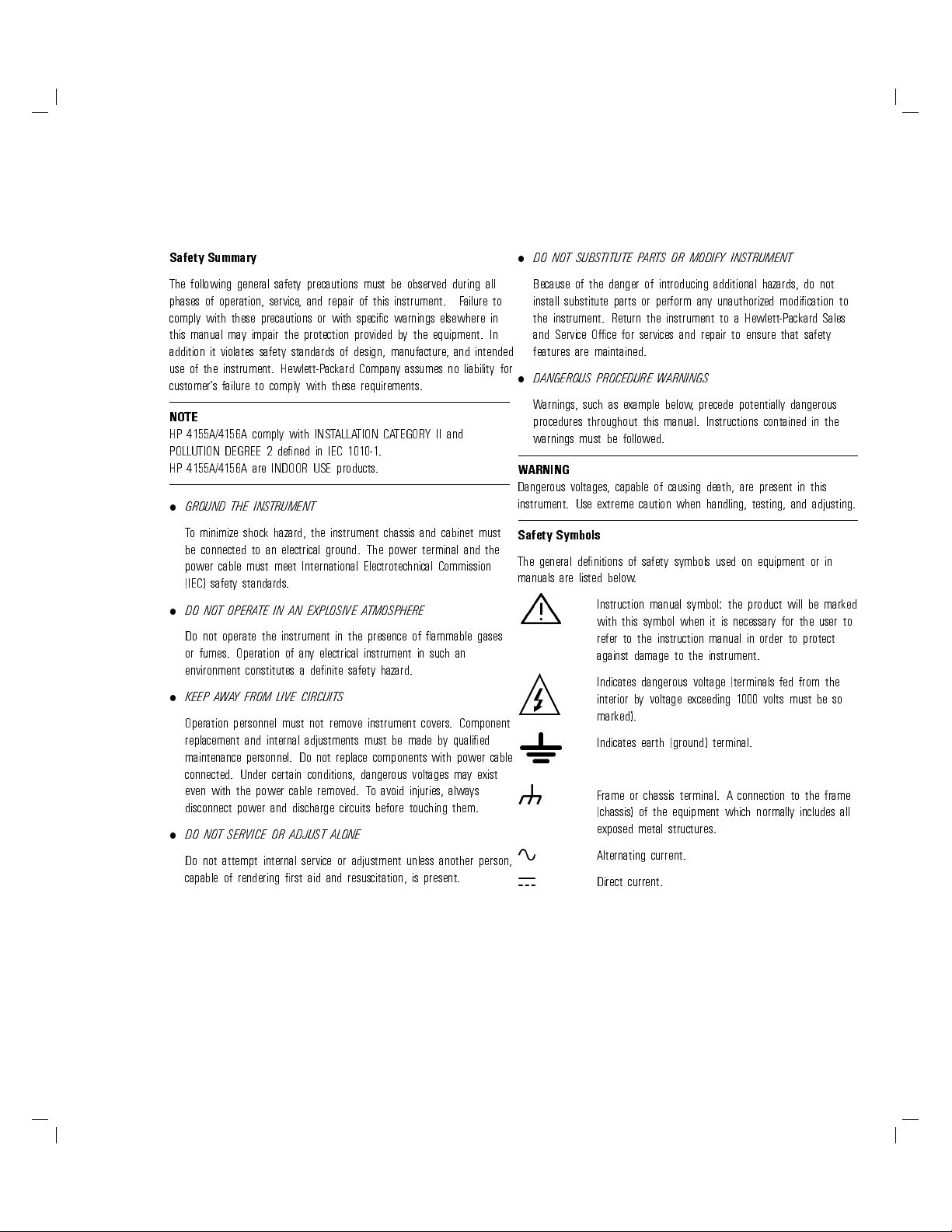
Safety Symbols
The general denitions of safety symbols used on equipment or in
manuals are listed below.
Instruction manual symbol: the product will be marked
L
with this symbol when it is necessary for the user to
refer to the instruction manual in order to protect
against damage to the instrument.
Indicates dangerous voltage (terminals fed from the
interior by voltage exceeding 1000 volts must be so
marked).
Indicates earth (ground) terminal.
K
Frame or chassis terminal. A connection to the frame
(chassis) of the equipment which normally includes all
exposed metal structures.
A
F
Alternating current.
Direct current.
ON (Supply).
OFF (Supply).
Herstellerbescheinigung
GEAUSCHEMISSION
WARNING
CAUTION
The warning sign denotes a hazard. It calls attention to
a procedure, practice, condition or the like, which, if
not correctly performed or adhered to, could result in
injury or death to personnel.
The caution sign denotes a hazard. It calls attention to
an operating procedure, practice, condition or the like,
which, if not correctly performed or adhered to, could
result in damage to or destruction of part or all of the
product.
Lpa<70 dB
am Arbeitsplatz
normaler Betrieb
nach DIN 45635 T.19
Manufacturer's Declaration
ACOUSTIC NOISE EMISSION
Lpa<70 dB
operator position
normal operation
per ISO 7779


Introduction
HP 4155A/4156A is an electronic instrument for measuring and analyzing the
characteristics of semiconductor devices. This one instrument allows you to
perform
both
measurement
and
analysis of measurement results.
highly accurate measurements.
HP 4155A/4156A has four highly accurate source/monitor units (SMUs), two
voltage source units (VSUs), and two voltage measurement units (VMUs).
The HP 4156A is designed for Kelvin connections and has high-resolution
SMUs (HRSMUs), so HP 4156A is especially suited for low resistance and low
current measurements.You can measure voltage values with a resolution of
0.2V by using the dierential measurement mode of VMUs.
reliability testing.
HP 4155A/4156A can perform
stress
testing. That is, can force a specied dc
voltage or current for the specied duration.
Also, you can force ac stress by using pulse generator units (PGUs), which are
installed in HP 41501A SMU/Pulse Generator Expander. The HP 41501A is
attached to HP 4155A or HP 4156A, and can be equipped with a ground unit
(GNDU), high power SMU (HPSMU), two medium power SMUs (MPSMUs), or
two PGUs.
data storing and printing.
HP 4155A/4156A can print and store, in addition to performing measurement
and analysis.You can store measurement setup information, measurement
data, and instrument setting information on a 3.5-inch diskette inserted into
the disk drive of HP 4155A/4156A. And you can print the setting information
and measurement results on a plotter or printer that is connected to
HP 4155A/4156A.
remote control.
HP 4155A/4156A can be controlled by an external controller via HP-IB by
using remote control commands. These commands are based on Standard
Commands for Programmable Instruments (SCPI), so you can easily develop
measurement programs.
HP 4155A/4156A has internal HP Instrument BASIC, so you can develop and
execute measurement programs by using the HP 4155A/4156A only, without
using an external controller.
ix
In This Manual
This manual gives step-by-step instructions for performing common HP
4155A/4156A tasks, and consists of the following chapters:
NOTE
If you have never used the HP 4155A/4156A or HP 4145A/B, read the HP 4155A/4156A
Guide
rst before reading this manual. The
Quick Start Guide
gives you an overview of the product
Quick Start
and a brief introduction, which is a good rst step for beginners.
Introducing the HP 4155A/4156A
This chapter is an overview of the HP 4155A/4156A.
Installation
This chapter describes how to install HP 4155A/4156A, accessories
, and
peripherals.
Making a Measurement
This chapter describes device connections, making a sweep measurement,
knob sweep measurement, and sampling measurement, and forcing stress.
Analyzing Measurement Results
This chapter describes how to analyze measurement results manually and
automatically.
Filer and Hardcopy
This chapter describes how to print or plot out measurement results or
measurement setups.
If You Have a Problem
This chapter provides problem-solving information that you may encounter.
Manual Changes Depending on ROM Version
Index
x
Other Manuals.
Also the following manuals about HP 4155A/4156A are available:
User's Dictionary Reference
This manual is a dictionary reference for all parts and functions of the HP
4155A/4156A, and consists of the following chapters:
Measurement Units
Measurement Mode
Measurement Functions
Page Organization
Print/Plot Function
Data Variable and Analysis Function
Softkey Maps and External Keyboard
Specications
Accessories and Options
Manual Changes Depending on ROM Version
Index
Programmer's Guide
This manual provides information about controlling the HP 4155A/4156A
by remote command via HP-IB interface and HP Instrument B
ASIC, and
consists of the following chapters:
Using HP Instrument BASIC
Reference: HP Instrument BASIC
Getting Started on Programming the HP 4155A/4156A
HP 4155A/4156A SCPI Programming
Running HP 4145A/B Program Directly on HP 4155A/4156A
Sample Application Programs
Manual Chages Depending on ROM Version
HP-IB Command Reference
This manual is a complete reference of HP-IB commands
the following chapters:
SCPI Commands
HP 4145B Syntax Commands
Manual Changes Depending on ROM Version
Index
Quick Start Guide
, and consists of
xi
This manual is mainly for beginners and provides brief instructions about
using HP 4155A/4156A.
Text Conventions.
The following text conventions are used in this manual:
4
Front-panel key
NNNNNNNNNNNNNNNNNNNNNNNNNNNNN
Softkey
Screen Text
Italic
5
Represents a key physically located on HP 4155A/4156A
or external keyboard.
Represents a softkey that appears on screen of
HP 4155A/4156A.
Represents text that appears on screen of
HP 4155A/4156A.
Refers to a related document, or is used for emphasis
.
xii
Contents
1. Introducing the HP 4155A/4156A
Overview of HP 4155A/4156A . . . . . . . . . . . .
Conguration of HP 4155A/4156A and HP 41501A . .
Front View of HP 4155A/4156A . . . . . . . . . . .
Rear View of HP 4155A/4156A . . . . . . . . . . .
1-3
1-4
1-5
1-9
L
L
L
. . . . . . . . . . . . . . . . . . . . .
. . . . . . . . . . . . . . . . . . . . .
. . . . . . . . . . . . . . . . . . . . .
Front and Rear View of HP 41501A . . . . . . . . .
L
. . . . . . . . . . . . . . . . . . . . .
An Overview of Functions . . . . . . . . . . . . . .
Operation and Control . . . . . . . . . . . . . . .
Measurements and Results Display . . . . . . . . .
Graphical Analysis . . . . . . . . . . . . . . . .
Data Storage . . . . . . . . . . . . . . . . . . .
Plotting and Printing . . . . . . . . . . . . . . .
2. Installation
L
. . . . . . . . . . . . . . . . . . . . .
Requirements . . . . . . . . . . . . . . . . . . . .
Power Requirements . . . . . . . . . . . . . . . .
Power Cable . . . . . . . . . . . . . . . . . . .
Ventilation Requirements . . . . . . . . . . . . . .
Operating Environment . . . . . . . . . . . . . .
Cleaning . . . . . . . . . . . . . . . . . . . . .
Setting up HP 4155A/4156A . . . . . . . . . . . . .
To Inspect HP 4155A/4156A and Accessories . . . . .
To Install HP 41501A SMU/Pulse Generator Expander
To Check HP 4155A/4156A Operation . . . . . . . .
Installing Accessories . . . . . . . . . . . . . . . .
To Install Connector Plate . . . . . . . . . . . . .
To Connect InterlockTerminal . . . . . . . . . . .
1-10
1-10
1-11
1-12
1-13
1-19
1-20
1-22
1-25
1-26
1-27
2-2
2-3
2-4
2-5
2-7
2-7
2-7
2-8
2-8
2-9
2-10
2-12
2-13
2-17
Contents-1

Change 1
To Connect Connector Plate and DUT . . . . . . . .
To Install HP 16442A Test Fixture ........... 2-29
To Install HP 16441A R-Box . . . . . . . . . . . .
To Install HP 16440A SMU/Pulse Generator Selector .
To Connect HP 16440A Selector to HP 4155A/56A . .
3. Making a Measurement
Connection to Device Under Test (DUT) . . . . . . . .
To Mount a DUT on Test Fixture . . . . . . . . . .
To Make Connections to Reduce Leakage Current . . .
To Make Connections to Measure Low Resistance (For
HP 4156A Only) . . . . . . . . . . . . . . . .
Sweep Measurements . . . . . . . . . . . . . . . .
To Dene Sweep Measurement Units . . . . . . . . .
To Set up Primary Sweep Source . . . . . . . . . .
To Set up Secondary Sweep Source . . . . . . . . .
To Set up Synchronous Sweep Source . . . . . . . .
To Set up Constant Output . . . . . . . . . . . . .
To Set up SMU Pulsed Output . . . . . . . . . . .
To Set up PGU Pulsed Output . . . . . . . . . . .
To Output Same Value Before and After Measurements
To Dene a User Function . . . . . . . . . . . . .
To Set up Graphical Display of Measurement Results .
To Set up List Display of Measurement Results . . . .
To Execute or Stop Measurement . . . . . . . . . .
To Control R-Box . . . . . . . . . . . . . . . . .
Knob Sweep Measurements . . . . . . . . . . . . . .
To Execute Knob Sweep Measurement . . . . . . . .
To Stop Knob Sweep Measurement . . . . . . . . .
Sampling Measurements . . . . . . . . . . . . . . .
To Dene Sampling Measurement Units . . . . . . .
To Set up Sampling Parameters . . . . . . . . . . .
To Set up Constant Output . . . . . . . . . . . . .
To Dene Measurement Stop Conditions . . . . . . .
Stress Force . . . . . . . . . . . . . . . . . . . .
To Set up Stress Source Channels . . . . . . . . . .
To Set up Stress Condition/Timing . . . . . . . . .
To Set up AC (Pulse) Stress . . . . . . . . . . . .
To Set up DC Stress . . . . . . . . . . . . . . . .
ToForce Stress . . . . . . . . . . . . . . . . . .
To Control Selector for Switching SMU and PGU . . .
2-22
2-35
2-38
2-45
3-3
3-4
3-6
3-8
3-10
3-12
3-14
3-16
3-18
3-20
3-21
3-24
3-27
3-28
3-30
3-32
3-33
3-34
3-37
3-38
3-42
3-43
3-45
3-47
3-49
3-51
3-53
3-55
3-57
3-60
3-62
3-64
3-66
Contents-2
4. Analyzing Measurement Results
Manual Analysis . . . . . . . . . . . . . . . . . .
To Specify a MeasurementPoint on Curve . . . . . .
To Specify between MeasurementPoints on Curve. . .
To DisplayorMove Cursor . . . . . . . . . . . . .
To Adjust Display Range to Measurement Curve
Automatically . . . . . . . . . . . . . . . . .
To Zo om the Display Range . . . . . . . . . . . .
To Center Display at Cursor Lo cation . . . . . . . .
To Draw Line through Two Sp ecied Points . . . . .
To Draw Line through Specied Point with Specied
Gradient . . . . . . . . . . . . . . . . . . .
To DrawTangent to Specied Point of Measurement
Curve. . . . . . . . . . . . . . . . . . . . .
To Draw Regression Line for Specied Region . . . . .
To Display and Select a Line . . . . . . . . . . . .
To Display Grid on the Graph . . . . . . . . . . .
To Change Data Variable on Graph . . . . . . . . .
To Change Range of X or Y Axis Scale .
. . . . . . .
To Change Variable Assigned to X, Y1, or Y2 Axis . .
ToOverlayanInternal Memory Measurement Curve
onto Plotting Area . . . . . . . . . . . . . . .
To Scroll the LIST Page . . . . . . . . . . . . . .
To DisplayorMove Marker on LIST Page . . . . . .
To Change Variables of LIST page . . . . . . . . . .
Automatic Analysis . . . . . . . . . . . . . . . . .
To Draw Line by Specifying TwoPoints . . . . . . .
To Draw Line by Specifying Gradient and One Point. .
To DrawTangent to Specied MeasurementPoint. . .
To Draw Regression Line by Sp ecifying TwoPoints . .
To Display Marker at Specied Point . . . . . . . .
Change 1
4-3
4-4
4-6
4-8
4-10
4-11
4-12
4-13
4-15
4-17
4-19
4-22
4-23
4-24
4-25
4-26
4-27
4-29
4-30
4-32
4-33
4-34
4-36
4-38
4-40
4-43
5. Filer
File Operations . . . . . . . . . . . . . . . . . . .
To List File Names Stored on Diskette . . . . . . . .
To Store Setup or Result Data onto Diskette . . . . .
To Store Setup or Result Data into Internal Memory . .
To Store Result Data in Spreadsheet Format . . . . .
To Load Setup or Result Data from Diskette . . . . .
To Load Setup or Result Data from Internal Memory .
To Rename a File on Diskette . . . . . . . . . . . .
5-3
5-5
5-7
5-9
5-11
5-13
5-16
5-18
Contents-3
Change 1
To Remove a File from Diskette . . . . . . . . . . .
To Copy File on Diskette to Another Diskette ...... 5-21
To Copy Setup or Result Data from Internal Memory to
Diskette . . . . . . . . . . . . . . . . . . . .
To Initialize a Diskette . . . . . . . . . . . . . . .
To Backup a Diskette . . . . . . . . . . . . . . .
6. If You Have A Problem
When You Install the HP 4155A/4156A . . . . . . . .
If HP 4155A/4156A cannot be Powered on . . . . . .
If Measurement Units of HP 41501A are not Displayed
on the CHANNELS: CHANNEL DEFINITION Page
If External Keyboard do es not Work . . . . . . . . .
If Display Page do es not App ear after Applying P
If HP 16442A Test Fixture is not Stable . . . . . . .
When You Make A Measurement . . . . . . . . . . .
If Measured Value Oscillates when Measuring
High-Frequency Devices . . . . . . . . . . . . .
If Measured Value Oscillates when Measuring Negative
Resistance . . . . . . . . . . . . . . . . . . .
If Noise Aects the Measured Values . . . . . . . . .
If Measured Voltage has some Error when Forcing a
Large Current . . . . . . . . . . . . . . . . .
If Large Current Causes High Temperature (Thermal
Drift) . . . . . . . . . . . . . . . . . . . . .
If MeasurementTakes More Time than Specied . . .
If Measurement Damages the Device under Test . . . .
If You Get Unexpected Data when Performing Sampling
Measurement . . . . . . . . . . . . . . . . .
If Errors Occur . . . . . . . . . . . . . . . . . . .
If Errors Occur when You Perform Self-calibration or
Diagnostics . . . . . . . . . . . . . . . . . .
If an error o ccurs when you operate HP 4155A/4156A .
If a Measurement Data Status is Displayed. . . . . . .
ower .
5-19
5-23
5-24
5-26
6-4
6-5
6-6
6-7
6-7
6-7
6-8
6-9
6-10
6-12
6-13
6-13
6-14
6-14
6-15
6-16
6-17
6-25
6-40
7. Manual Changes Depending on ROM Version
Change 1 . . . . . . . . . . . . . . . . . . . . . .
Index
Contents-4
7-3
Figures
1-1. Front View of HP 4155A/4156A . . . . . . . . . . . . . . 1-5
1-2. Rear View of HP 4155A/4156A .............. 1-9
1-3. Front and Rear View of HP 41501A . . . . . . . . . . . . 1-12
1-4. Rear View of HP 41501A Option 402 ........... 1-14
1-5. Rear View of HP 41501A Option 410 ........... 1-15
1-6. Rear View of HP 41501A Option 412 ........... 1-16
1-7. Rear View of HP 41501A Option 420 ........... 1-17
1-8. Rear View of HP 41501A Option 422 ........... 1-18
2-1. Power Cables . . . . . . . . . . . . . . . . . . . . . .
2-2. Dimensions of Connector Plate for HP 4155A
(HP Part Number: 04155-60006) . . . . . . . . . . . .
2-3. Dimensions of Connector Plate for HP 4156A
(HP Part Number: 04156-60002) . . . . . . . . . . . .
2-4. Dimensions of Connector Plate for HP 41501A
(HP Part Number: 41501-60004) . . . . . . . . . . . .
2-5. Dimensions of Interlock Switch (HP part number 3101-0302) .
2-6. Dimensions of Interlock Switch (HP part number 3101-3241) .
2-7. Dimensions of LED (HP part number 1450-0641) ...... 2-21
2-5
2-14
2-15
2-16
2-20
2-20
Tables
1-1. Conguration of HP 41501A ............... 1-4
2-1. Connectors on Connector Plate . . . . . . . . . . . . . .
Contents-5
2-15

Contents

1
Introducing the HP
4155A/4156A
Introducing the HP 4155A/4156A
The HP 4155A semiconductor parameter analyzer and HP 4156A precision
semiconductor parameter analyzer are made for use in semiconductor
laboratories and factories. The HP 4155A/4156A can measure device
characteristics. The HP 4155A/4156A can do the following:
Perform measurements.
Graph the device characteristics.
Extract device parameters.
Perform go, no-go evaluation.
Perform reliability (stress test) evaluation.
The HP 4155A/4156A is easy to operate and can perform automatic graphical
analysis like the HP 4145B. In addition, the HP 4155A/4156A is also easy to
use in a system, which expands areas of application to quality assurance and
in-line monitoring.
In this chapter.
This chapter provides a view of front and rear panels of the HP 4155A/4156A
and its accessories, and briey describes the HP 4155A/4156A functions.
1-2
Overview of HP 4155A/4156A
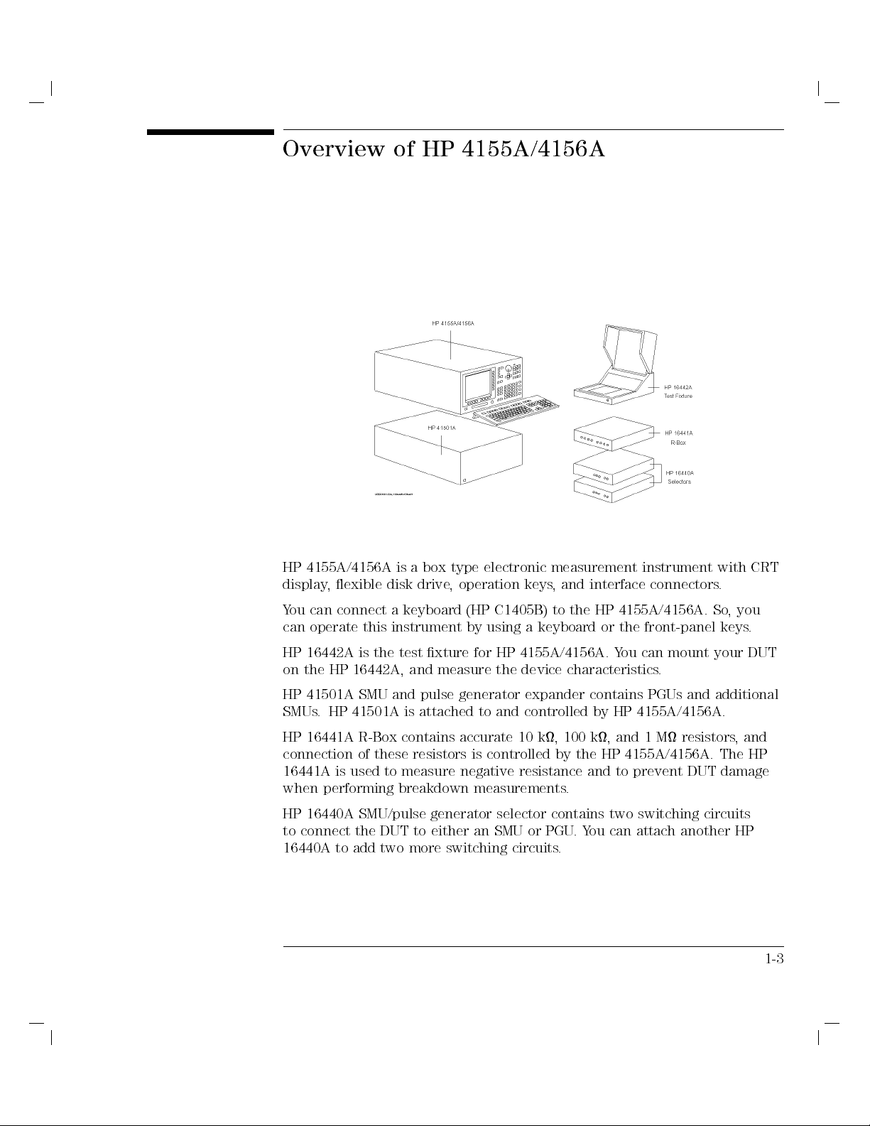
HP 4155A/4156A is a box type electronic measurement instrument with CRT
display, exible disk drive, operation keys, and interface connectors.
You can connect a keyboard (HP C1405B) to the HP 4155A/4156A. So
can operate this instrument by using a keyboard or the front-panel keys
HP 16442A is the test xture for HP 4155A/4156A. Y
on the HP 16442A, and measure the device characteristics
HP 41501A SMU and pulse generator expander contains PGUs and additional
SMUs. HP 41501A is attached to and controlled by HP 4155A/4156A.
HP 16441A R-Box contains accurate 10 k, 100 k, and 1 M resistors, and
connection of these resistors is controlled by the HP 4155A/4156A. The HP
16441A is used to measure negative resistance and to prevent DUT damage
when performing breakdown measurements.
HP 16440A SMU/pulse generator selector contains two switching circuits
to connect the DUT to either an SMU or PGU.You can attach another HP
16440A to add two more switching circuits.
ou can mount your DUT
.
, you
.
1-3
Introducing the HP 4155A/4156A
Overview of HP 4155A/4156A
Conguration of HP 4155A/4156A and HP 41501A
HP 4155A, HP 4156A, and HP 41501A are frames that contain the
measurement units. The measurement units are installed before the product
is shipped from factory. User cannot recongure the installed units.
HP 4155A conguration:
four medium power source monitor units (MPSMUs).
two voltage source units (VSUs).
two voltage monitor units (VMUs).
HP 4156A conguration:
four high resolution source monitor units (HRSMUs).
two voltage source units (VSUs).
two voltage monitor units (VMUs).
HP 4156A has higher measurement resolution. For details about
measurement range and resolution, refer to \Measurement Units" in
4155A/4156A User's Dictionary Reference
.
HP
HP 41501A conguration:
HP 41501A is attached to the HP 4155A/4156A at your site
. See Chapter 2
on how to install the HP 41501A.
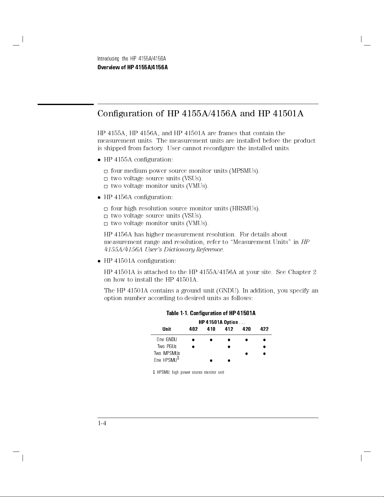
The HP 41501A contains a ground unit (GNDU). In addition, you specify an
option number according to desired units as follows:
Table 1-1. Conguration of HP 41501A
HP 41501A Option
Unit
One GNDU
Two PGUs
Two MPSMUs
One HPSMU
1
HPSMU: high power source monitor unit
402 410 412 420 422
1
...
1-4
Front View of HP 4155A/4156A
Introducing the HP 4155A/4156A
Overview of HP 4155A/4156A
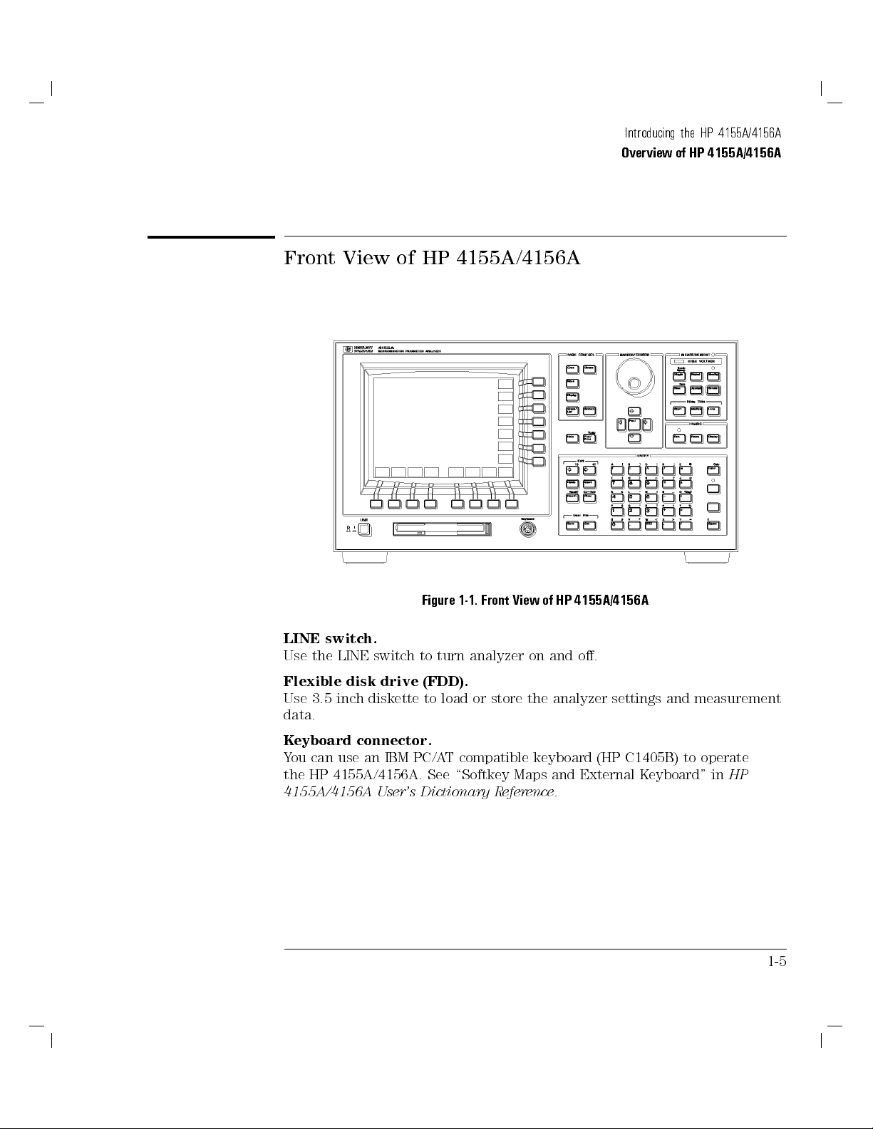
Figure 1-1. Front View of HP 4155A/4156A
LINE switch.
Use the LINE switch to turn analyzer on and o.
Flexible disk drive (FDD).
Use 3.5 inch diskette to load or store the analyzer settings and measurement
data.
Keyboard connector.
You can use an IBM PC/AT compatible keyboard (HP C1405B) to operate
the HP 4155A/4156A. See \Softkey Maps and External K
4155A/4156A User's Dictionary Reference
.
eyboard" in
HP
1-5
Introducing the HP 4155A/4156A
Overview of HP 4155A/4156A
PAGE CONTROL key group.
Page Control keys are used to change the pages.
4
Chan
5
Moves to CHANNELS page group.You dene channels, user
functions, and user variables.
4
Meas
5
Moves to MEASURE page group.You set the output parameters,
measurement parameters, and so on.
4
Display
5
Moves to DISPLAY page group.You set the result display
format, auto analysis denitions, and so on.
4
Graph/List
5
Moves to GRAPH/LIST page group. This softkey toggles between
GRAPH and LIST pages.
4
Stress
5
Moves to STRESS page group.You dene the stress channels,
set the stress parameters, and monitor the stress forcing.
4
System
5
Moves to SYSTEM page group.You operate on diskette les,
set up plotting and printing environment, dene colors of the
display, and so on.
MARKER/CURSOR key group.
Rotary knob and arrow keys of the Marker/Cursor key group are used to
move the marker and cursor.
Rotary knob Moves the marker, or increases or decreases setup value.
4(5,4
4*5
4
Fast
)
, and
5
5
,
Moves eld pointer or cursor.
4
5
+
Moves the marker or cursor faster. When you rotate the rotary
knob or press the arrow keys with holding
4
5
key down, the
Fast
marker or cursor moves faster.
1-6
Introducing the HP 4155A/4156A
Overview of HP 4155A/4156A
MEASUREMENT key group.
Measurement keys control the measurement, stress, and integration time.
4
Single
5
Executes the measurement once, then returns to the idle state
(or standby state if standby is enabled for the channel) after the
measurement is nished. Measurement data is updated, so data
of previous measurement is lost. Pressing the green key, then
4
5
4
Repeat
key starts
Single
5
Starts and repeats the measurement continuously. Measurement
knob sweep
measurement.
data is updated, so data of previous measurement is lost. To
4
Append
stop the measurement, press
5
Executes the measurement once, then returns to idle state
4
Stop
5
key.
(or standby state if standby is enabled for the channel) after
measurement is nished. Measurement data is appended to data
of previous measurement.
4
Stop
5
Stops the measurement or stress. Standby enabled channels
return to standby state, and other channels return to idle state.
4
Standby
5
Toggles between the standby enabled (Standby indicator is lit)
and disabled states. If Standby indicator is lit, then
STBY ON
channels change to standby state (instead of idle state) when
measurement or stress nishes.
4
5
key has no aect on
Stop
standby state.
4
Stress
4
Short
4
Medium
and
5
5
,
4
Long
5
Forces the specied stress. The guide around this key prevents
you from accidently pressing the
4
Stress
5
key.
Sets the integration time to SHORT, MEDIUM, or LONG,
,
respectively.
5
MEASUREMENT indicator.
This indicator lights when HP 4155A/4156A is in the measurement state.
HIGH VOLTAGE indicator.
This indicator lights when a unit forces more than 40 V
.
Standby indicator.
This indicator lights when the HP 4155A/4156A is standby enabled, which
means that the channels that are standby enabled (
STBY ON
) will return to
the standby state after the measurement is nished.
1-7
Introducing the HP 4155A/4156A
Overview of HP 4155A/4156A
IBASIC key group.
IBASIC keys control the IBASIC program execution.
4
Run
5
Starts the IBASIC program that is in memory. The indicator is
on during program execution.
4
Pause
4
Display
5
5
Pauses the IBASIC program execution.
Toggles between the IBASIC screen and measurement screen.
Run indicator.
When an IBASIC program is running, this indicator lights.
ENTRY key group.
You enter or modify data such as output values, comments, and variable
names.
Character keys Are used to enter alphanumeric and special characters.
4
Enter
5
After you enter desired characters into the data entry
eld, press this key. The characters are entered at the
eld pointer location.
Also, you can use the green key to calculate the value of
the data entry eld. For example, if you press
greenkey
4
5
, the result (24) appears.
Enter
4
454*546
5
Blue key Changes entry mode to blue-key shift mode, and lights
the indicator. In this mode, you can enter the blue
characters that are printed above the keys. Pressing blue
key again changes to normal mode. Indicator turns o.
Green key Changes entry mode to green-key shift mode. This mode
is eective for the next pressed key, then changes back to
normal mode.
Edit keys Are used to edit the characters in the data entry eld.
User File keys Are used to operate quickly on a diskette le. Pressing
4
5
moves into the ler's SAVE function, and pressing
Save
4
5
moves into the ler's GET function.
Get
4
5
key.
Help
Pressing
4
Plot/Print
Pressing
your plotter, printer, or diskette le. If you press green key and
4
5
Help
5
key.
4
Plot/Print
displays the
5
prints the setup information and measurement results to
help
pages.
4
Plot/Print
5
,
the screen image is dumped to plotter, printer, or diskette le.
1-8
Rear View of HP 4155A/4156A
Introducing the HP 4155A/4156A
Overview of HP 4155A/4156A
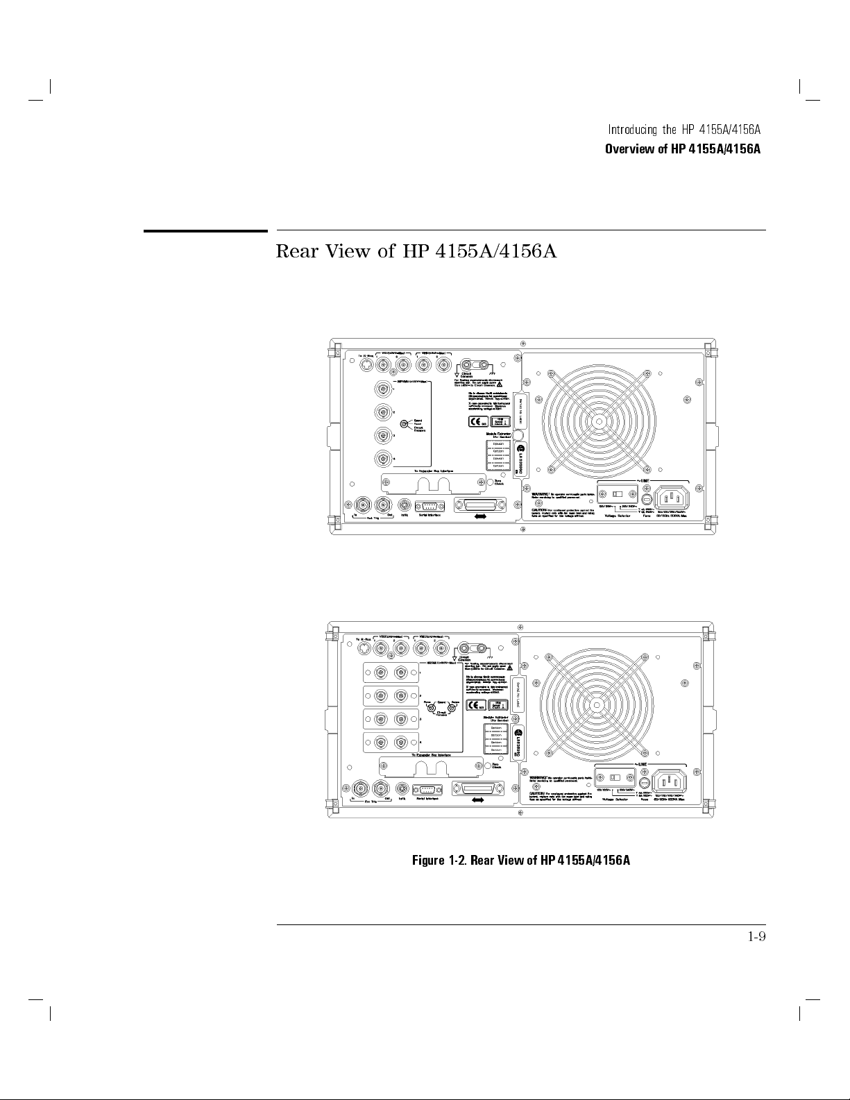
Figure 1-2. Rear View of HP 4155A/4156A
1-9
Introducing the HP 4155A/4156A
Overview of HP 4155A/4156A
To R-Box terminal.
\To R-Box" terminal is a 10-pin connector.To use R-Box, connect this
terminal to control terminal of HP 16441A R-Box.
VSU terminals.
VSU output terminals are BNC connectors.To use VSUs, connect these
terminals to VSU terminals of HP 16442A or connector plate.
VMU terminals.
VMU input terminals are BNC connectors.To use VMUs, connect these
terminals to VMU terminals of HP 16442A or connector plate.
L
WARNING
L
Circuit Common (
) and Frame ground ( ) terminals.
For oating measurement, remove the shorting bar (HP part number
5000-4206).
6
Do not oat the Circuit Common terminal at voltages greater than
42 V
referenced to frame ground. Failure to heed this warning may result in
damage to HP 4155A/4156A.
Serial number.
You need this
serial number
when using the telephone assistance program
(HP HelpLine).
Voltage selector.
Voltage selector must be in proper position. Line voltage and position are:
Line Voltage Position
90|132 Vac left
198|264 Vac right
Fuse.
Use the following fuse:
Line Fuse type HP part number
100/120 Vac UL/CSA T 8A, 250 Vac 2110-0383
220/240 Vac UL/CSA T 4A, 250 Vac 2110-0014
LINE input receptacle.
AC power cable is connected to this receptacle.
1-10
Introducing the HP 4155A/4156A
Overview of HP 4155A/4156A
SMU terminals.
HP 4155A has four triaxial connectors. HP 4156A has eight triaxial
connectors, and you can use Kelvin connections. When you use HP 16442A
test xture and Kelvin connections, up tp 3 SMUs can be connected to HP
16442A test xture.
To Expander Box Interface.
When you use HP 41501A, you insert the board for HP 41501A into this
interface.
Zero Check terminal.
Ground reference point of the HP 4155A/4156A.
Ext Trig terminals.
Two BNC connectors: one for trigger input, and one for trigger output.
L
WARNING
Intlk terminal.
Used in conjunction with interlock function of HP 4155A/4156A. If the Intlk
6
terminal is open, maximum SMU output is limited to
40 V. Be sure to
connect this terminal to HP 16442A test xture or connector plate before
performing measurement. If you use connector plate, you must install
interlock circuit. For details on how to install the interlock circuit, see \T
o
Connect Interlock Terminal" in Chapter 2.
Dangerous voltage of up to the maximum voltage of SMUs may be present
at force, guard, and sense terminals if the interlock terminal is shorted.
Serial Interface connector.
9-pin female connector for RS-232-C serial communication.
HP-IB connector.
Use HP 10833A/B/C/D HP-IB cable.
1-11
Introducing the HP 4155A/4156A
Overview of HP 4155A/4156A
Front and Rear View of HP 41501A
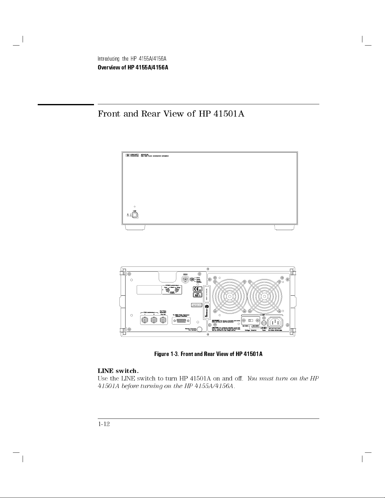
Figure 1-3. Front and Rear View of HP 41501A
LINE switch.
Use the LINE switch to turn HP 41501A on and o.
41501A before turning on the HP 4155A/4156A.
1-12
You must turn on the HP
 Loading...