

Page 1
Page 2

Table of Contents
EC DECLARATION OF CONFORMITY ................................................................................................... 3
1. Delivery Check .......................................................................................................................................... 4
2. Operating Instruction ................................................................................................................................. 4
2.1 Start-up and Rolling ............................................................................................................................. 4
2.2 Transport .............................................................................................................................................. 4
3. Maintenance ............................................................................................................................................... 5
4. Spare Part List, Roller ................................................................................................................................ 6
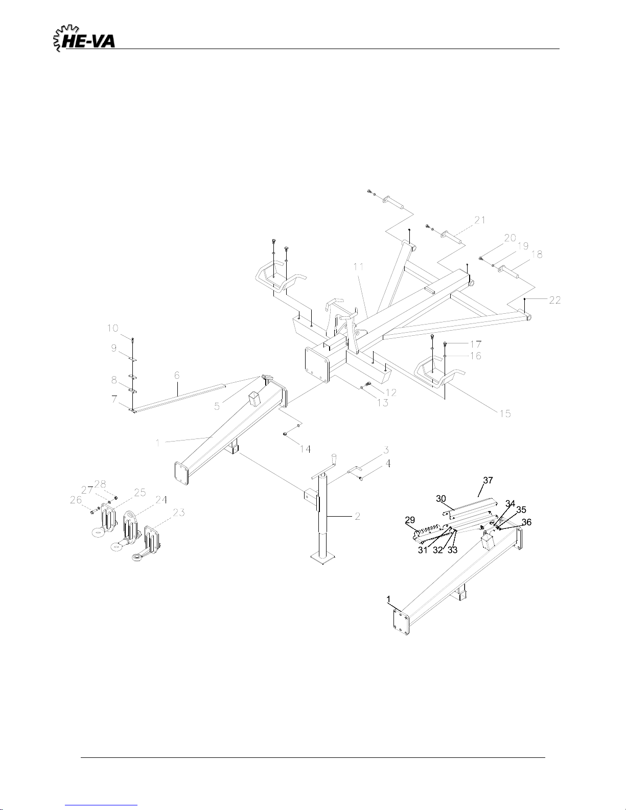
4.1 Drawbar before May 2010 ................................................................................................................... 6
4,2 Drawbar after May 2010 ...................................................................................................................... 8
4.3 Center Section .................................................................................................................................... 10
4.4 Wing Side Section .............................................................................................................................. 11
4.5 Center section for Ø620 rings after machine number: 342089 .......................................................... 12
4.6 Wing and Side Section Ø620 rings after machin number: 342089 .................................................... 13
4.7 Roller Block ....................................................................................................................................... 14
4.8 Hydraulic Roller ................................................................................................................................. 16
5. Spring-Board ............................................................................................................................................ 18
5.1 Installation of Cylinder on the Spring-Board ..................................................................................... 18
5.2 Spring-Board, Center Section ............................................................................................................. 18
5.3 Spring-Board – Left Side Section ...................................................................................................... 22
6. Lights ....................................................................................................................................................... 25
LED Light set ........................................................................................................................................... 25
Lighting set: El. diagram .......................................................................................................................... 26
7. Easy Change System ................................................................................................................................ 27
Page 3
EC DECLARATION OF CONFORMITY
in accordance with the EU Machinery Directive 2006/42/EC
applicable as from December 29th 2009:
HE-VA ApS
N. A. Christensensvej 34,
DK-7900 Nykøbing Mors
hereby confirms that the following machine has been manufactured in accordance with the Council
Directive 2006/42/EC.
The declaration comprises the following machine:
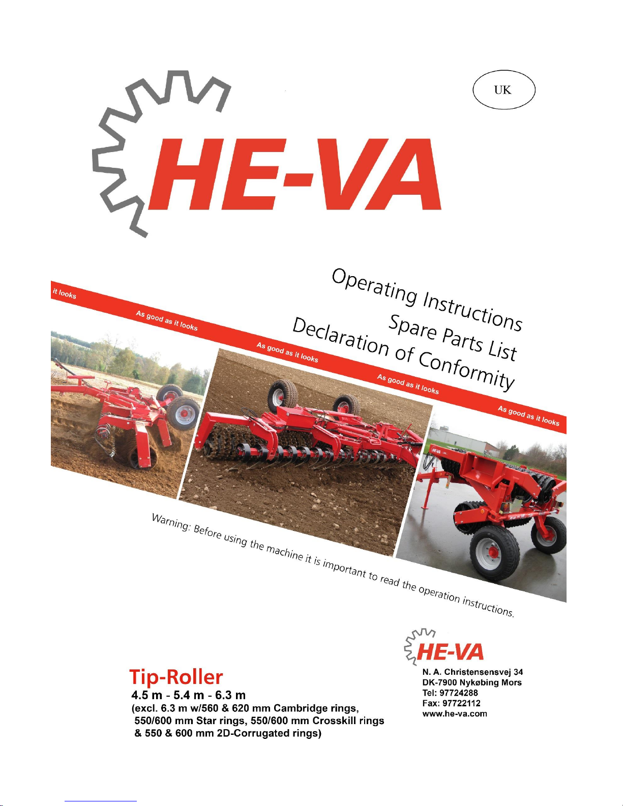
Tip – Roller 4,5m – 5,4m – 6,3m
Nykøbing the 29th December 2009
Villy Christiansen
The undersigned is furthermore authorised to compile technical documentation for the above machine.
Page 4

Tip Roller 4,5 / 5,4 / 6,3m (excl. 6,3 m w/620mm cambridge) 10/07-2018
4
1. Delivery Check
Check the roller for any damages. Check the hydraulic hoses for any cutting or squeezing damages.
Check that the other hydraulic components have not been damaged. Furthermore, you should check that
the roller blocks have not been exposed to impacts, which may have damaged the cast roller rings or the
double-sealed ball bearings.
Also check the transport wheels are tightened and working properly. Check the air pressure (approx. 3.8
bar / 55 psi)
2. Operating Instruction
2.1 Start-up and Rolling
When delivered from the factory, the roller will be in transport position. At start-up, the tractor is hitched
to the roller.
Important: Check that the hook height is between 400 and 500 mm.
Turn up the support leg and place in the drawbar. Now install the four hydraulic hoses.
The roller required two double-acting outlets.
The hoses for the tip cylinder are provided with red tie strap.
The hoses for the wing cylinder are provided with blue tie strap.
Important: Check that the male quick couplings installed by the factory fit the female quick couplings of
the tractor.
Now put pressure on the tip cylinder (red) so that the side sections are lifted free of the transport fittings.
Then put pressure on the wing cylinder (blue) so that the wings are turned backwards, as much as
possible.
Then depressurise the tip cylinder and the roller will tip forwards, down to working position. When the
tip cylinder is in bottom position, release the hydraulic lever, and the roller is ready for use.
2.2 Transport
When changing to transport position, the roller is tilted totally backwards by putting pressure on the tip
cylinder. Now pressurise the wing cylinder, and the side sections are tilted forwards towards the stop on
the transport fittings of the drawbar.
When both side sections lie in parallel with the drawbar, they are lowered into the transport fittings by
releasing the tip cylinder. Then all hydraulic hoses are released, and the roller is ready for transport.
Page 5
Tip Roller 4,5 / 5,4 / 6,3m (excl. 6,3 m w/620mm cambridge) 10/07-2018
5
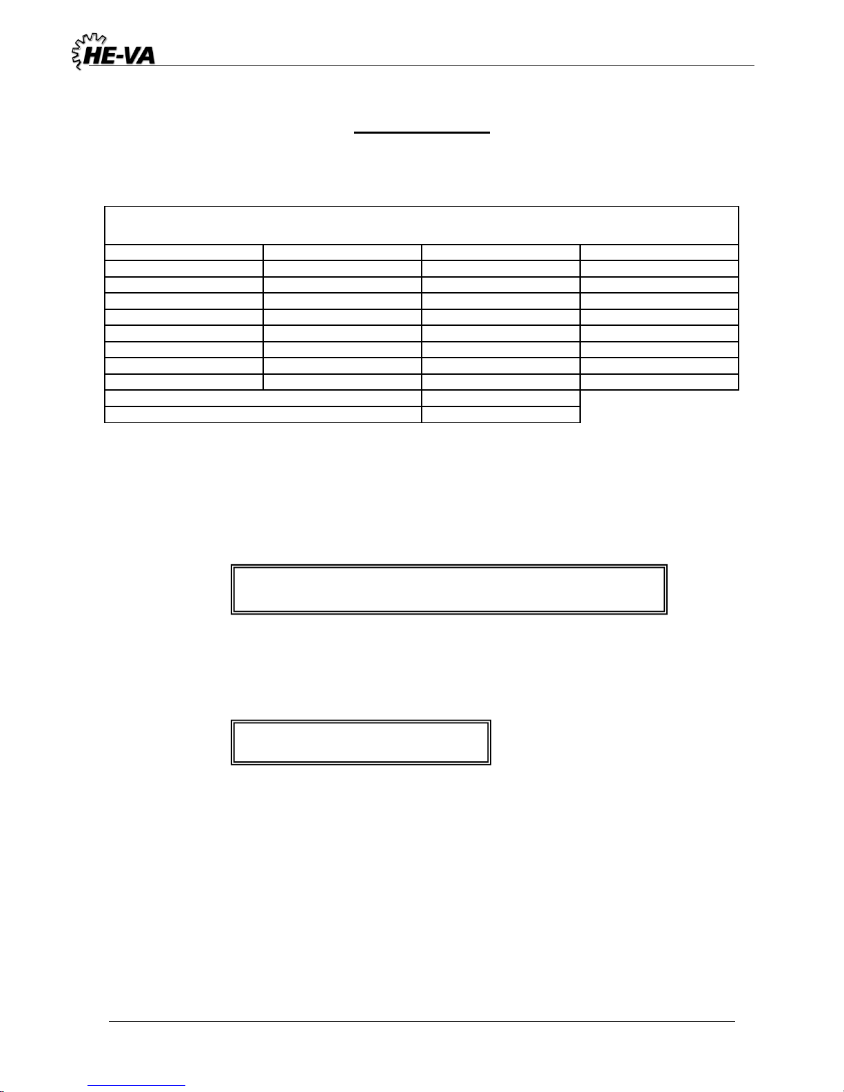
3. Maintenance
A. After approx. 10 hours of operation, retighten the wheels, ball bearings and stop rings. Check hoses,
fittings and cylinders for any leaks and retighten.
Maximum torque in Nm. w/lubricated thread
Metric thread
Quality 8.8
Quality 10.9
Quality 12.9
M10x1,5
47
65
79
M12x1,75
81
114
136
M14x2,0
128
181
217
M16x2,0
197
277
333
M18x2,5
275
386
463
M20x2,5
385
541
649
M22x2,5
518
728
874
M24x3,0
665
935
1120
Wheel nut M18x1,5 fine thread
433 Nm
Wheel nut M22x1,5 fine thread
803Nm
B. After every approx. 10 hours of operation, lubricate all movable parts in the side sections as well as
the three lubrication points of the wing cylinder. After every 30 hours of operation, lubricate the tip
cylinder pin and the three pins in the drawbar.
Important:
C. After the season, lubricate the roller with grease and oil.
Important:
Lubricate the piston rods with grease
The hydraulic system is filled with oil, type Hydro Texaco HD32.
Page 6
Tip Roller 4,5 / 5,4 / 6,3m (excl. 6,3 m w/620mm cambridge) 10/07-2018
6
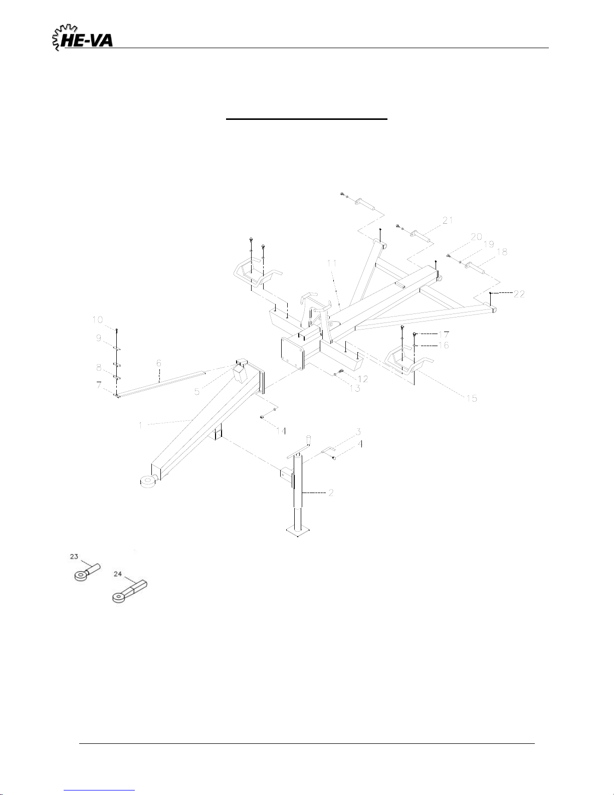
4. Spare Part List, Roller
4.1 Drawbar before May 2010
Page 7
Tip Roller 4,5 / 5,4 / 6,3m (excl. 6,3 m w/620mm cambridge) 10/07-2018
7
Pos.
Qty.
Designation
4,5m
5,4m
6,3m
1
630751000
Front drawbar (Danish)
1 1 1 1 630876000
Front drawbar (German)
1 1 1 2 690141100
Support leg 3500 kg (Danish)
1 1 1 2 690141101
Support leg 3500 kg (German)
1 1 1 3 69516094A
Pin ø16
1 1 1 4 0377400
Hairpin ø4 mm
1 1 1 5 0235040
M10x25 bolt
2 2 2 6 630771200
Parking device for hose
1 1 1
7
690210212
Weld. pl. f/double tube support (ø14, ø15, ø16, ø18)
1 1 1
8
690210210
Tube support, double ø14/ø14
2 2 2 9 690210211
Top pl. f/double tube support (ø14, ø15, ø16, ø18)
1 1 1
10
690210213
Screw for double tube support (ø14, ø15, ø16, ø18)
1 1 1
11
630715000
Back drawbar
1
11
630725000
Back drawbar
1
11
630755000
Back drawbar
1
12
690103128
Bolt M16x65 10.9
6 6 6
13
0272900
Facetted disc Ø16
12
12
12
14
0264090
Self-locking nut M16
6 6 6
15
630530300
Transport fittings Ø450 mm
2 2 2
15
630530400
Transport fittings Ø510 mm
2 2 2
16
0272900
Facetted disc Ø16
4 4 4
17
690103124
Bolt M16x35 mm
4 4 4
18
69530145G
Pin ø30 L=145
2 2 2
19
630532600
Locking bush for pin head
3 3 3
20
690101101
Bolt M12x25
3 3 3
21
69530175G
Pin ø30 L=175
1 1 1
22
0432510
Lub. nipple M8
3 3 3
23
690141211
Drawbar (Danish)
1 1 1
24
690105003
Drawbar (German)
1 1 1
Page 8
Tip Roller 4,5 / 5,4 / 6,3m (excl. 6,3 m w/620mm cambridge) 10/07-2018
8
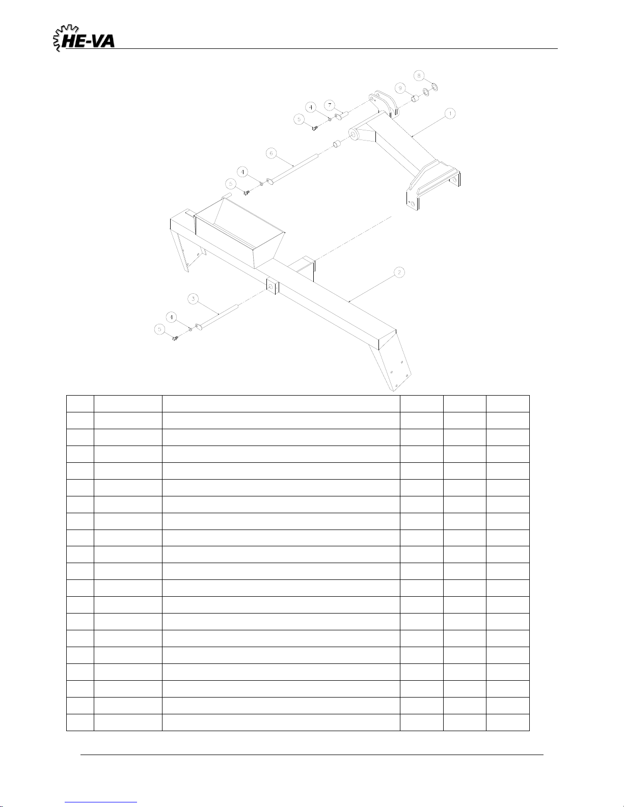
4,2 Drawbar after May 2010
Page 9
Tip Roller 4,5 / 5,4 / 6,3m (excl. 6,3 m w/620mm cambridge) 10/07-2018
9
Pos.
Qty.
Designation
4,5m
5,4m
6,3m
1
630757032
Front drawbar
1 1 1
1
630757097
Front drawbar for new parking device
1 1 1
2
690141100
Support leg 3500 kg
1 1 1
3
69516094A
Pin ø16
1 1 1
4
690133005
Hairpin ø4 mm
1 1 1
5
690103075
M10x25 bolt
2 2 2
6
630771200
Parking devise for hose
1 1 1
7
690210212
Weld.pl. f/double tube support (ø14, ø15, ø16, ø18)
1 1 1
8
690210210
Tube support, double ø14/ø14
2 2 2
9
690210211
Top pl. f/double tube support (ø14, ø15, ø16, ø18)
1 1 1
10
690210213
Screw f/double tube support (ø14, ø15, ø16, ø18)
1 1 1
11
630715000
Back drawbar
1
11
630725000
Back drawbar
1
11
630755000
Back drawbar
1
11
630536200
Back drawbar for Ø620 ringe after machin no. 342089
1
11
630546200
Back drawbar for Ø620 ringe after machin no. 342089
1
12
690103275
Bolt M16x65 10.9
6 6 6
13
0272290
Facetted disc Ø16
12
12
12
14
0264090
Self-locking nut M16
6 6 6
15
630530300
Transport fitting Ø450 mm
2 2 2
15
630530400
Transport fitting Ø510 mm
2 2 2
16
0272900
Facetted disc Ø16
4 4 4
17
690103124
Bolt M16x35 mm
4 4 4
18
69530145G
Pin Ø30 L=145
2 2 2
19
630532600
Locking bush for pin head
3 3 3
20
690101101
Bolt M12x25
3 3 3
21
69530175G
Pin Ø30 L=175
1 1 1
22
0432510
Lub. nipple M8
3 3 3
23
630757013
Drawbar Ø40 solid M16 bolts
1 1 1
23a
690105003
Loose towing eye, Ø40
24
630757025
Drawbar Ø50, pivoted, homologeret M16 bolts
1 1 1
24a
690105004
Loose towing eye, Ø50, pivoted, homologeret
25
630757028
Drawbar, Ø50, pivoted M16 bolts
1 1 1
25a
690141211
Loose towing eye, Ø50, pivoted
26
690103275
Bolt M16x65 10.9
6 6 6
27
0272290
Facetted disc Ø16
12
12
12
28
0264090
Self-locking nut M16
6 6 6
29
7345001
Parking devise for hose 8 places
1 1 1
29
7345002
Parking devise for hose 14 places
1 1 1
30
7345003
Cover for parking devise
1 1 1
31
0246060
Bolt 4 4
4
Page 10
Tip Roller 4,5 / 5,4 / 6,3m (excl. 6,3 m w/620mm cambridge) 10/07-2018
10
Pos.
Qty.
Designation
4,5m
5,4m
6,3m
32
0272240
Facetted disc 6mm
4 4 4
33
0264040
Self-locking nut M6, DIN985
4 4 4
34
0235360
Bolt M12x40mm,8.8 fzg
2 2 2
35
0272270
Facetted disc Ø12
4 4 4
36
0264070
Self-locking nut M12 DIN985
2 2 2
37
7345010
Complete parking device for hoses 8 places (pos 33-40)
37
7345019
Complete parking device for hoses 14 places (pos 33-40)
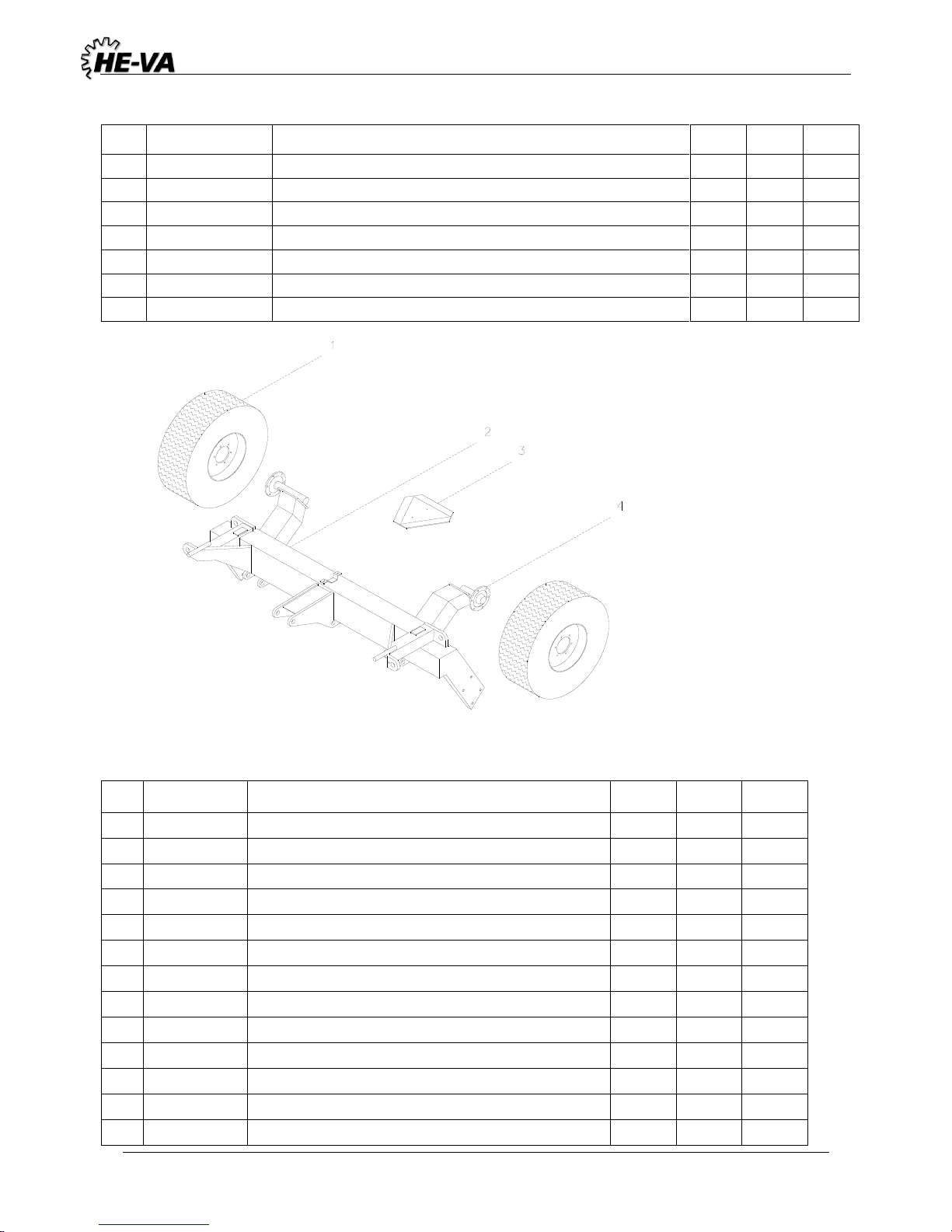
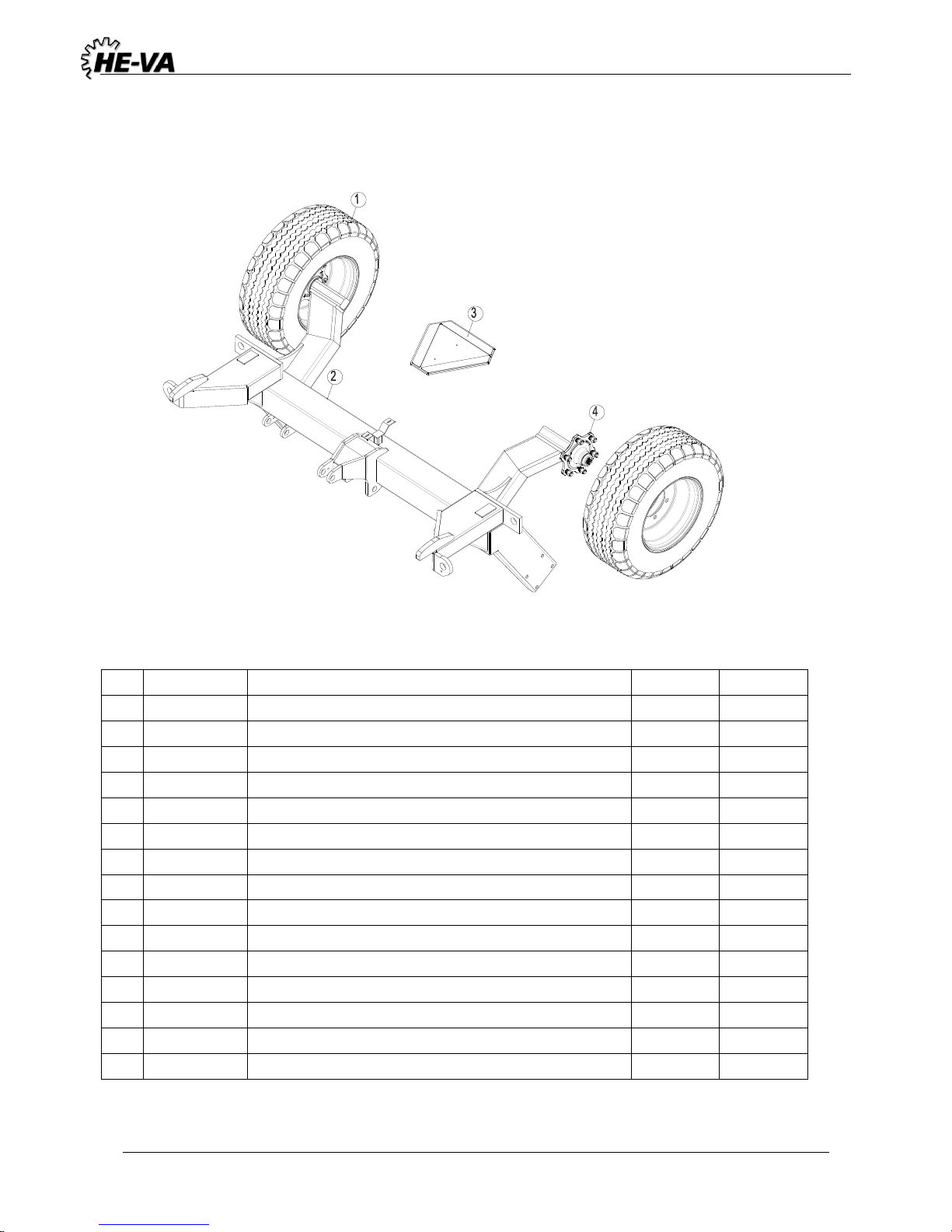
4.3 Center Section
Pos.
Qty.
Designation
4,5m
5,4m
6,3m
1
690141310
Wheel 10.0/75 x 15.3 10 layers
2 2 2
1
690141215
Hjul 11.5/80x15.3 - 14pr from machin no. 349836
2
2
630712000
Center frame
1
2
630722000
Center frame
1
2
630752000
Center frame
1
3
690142001
Warning triangle
1 1 1
3a
0233860
Bolt M5x20
2 2 2
3b
0264030
Nut M5
2 2 2
3c
0272230
Facetted disc Ø5
2 2 2
4
690141025
Hub 7050.6-M18/161-205 1700 kg
2 2 2
4a
690141039
Hub bolt M18x1,5x49
12
12
12
4b
0396470
Hub nut M18
12
12
12
4f
0395260
Hub cap Ø62
2 2 2
Page 11
Tip Roller 4,5 / 5,4 / 6,3m (excl. 6,3 m w/620mm cambridge) 10/07-2018
11
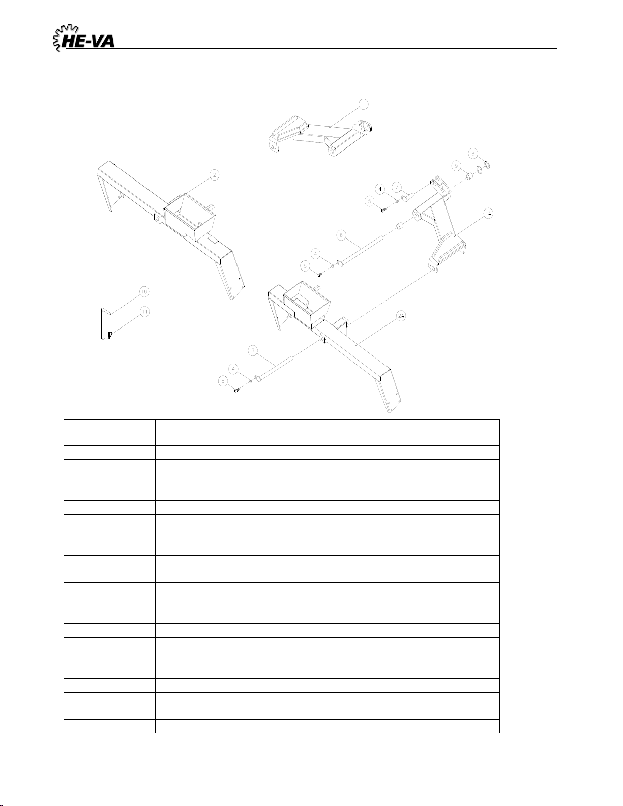
4.4 Wing Side Section
Pos.
Qty.
Designation
4,5m
5,4m
6,3m
1
630713011
Wing right
1
1
630723011
Wing right
1 1 630753007
Wing right
1 1 630713010
Wing left
1 1 630723010
Wing left
1
1
630753003
Wing left
1 2 630714000
Side section left
1
2
630724000
Side section left
1 2 630754000
Side section left
1 2 630714100
Side section right
1 2 630724100
Side section right
1
2
630754100
Side section right
1 3 69440425G
Pin ø40 L = 425
2 2 2
4
630532600
Bush for pin head
6 6 6
5
690101101
Bolt M12x25
6 6 6 6 69440525G
Pin ø40 L = 525
2 2 2 7 69430090G
Pin ø30 L = 90
2 2 2
8
690140714
Sliding disc Ø42/Ø66x1,5
4 4 4 9 0475100
Sliding bush Ø40/Ø44 L=40
4 4 4
Page 12
Tip Roller 4,5 / 5,4 / 6,3m (excl. 6,3 m w/620mm cambridge) 10/07-2018
12
4.5 Center section for Ø620 rings after machine number: 342089
Pos.
Qty.
Designation
4,5m
5,4m
1
690141310
Wheel10.0/75 x 15.3 10 layers
2
2
2
630536300
Centerframe
1
630546300
Centerframe
1
2
630536325
Centerframe w/side section lock
1
630546325
Centerframe w/side section lock
1
2a
630536521
Locking pin for side section lock Ø35 L=340
2
2
2b
690134010
Split for locking pin
2
2
3
0521010
Warning triangle
1
1
3a
0233860
Bolt M5x20
2
2
3b
0264030
Nut M5
2
2
3c
0272230
Facetted disc Ø5
2
2
4
690141025
Hub 7050.6-M18/160-205 1700 kg
2
2
4a
690141039
Hub bolt M18x1.5x49
12
12
4b
0396470
Hub nut M18
12
12
4f
0395260
Hub cap ø62
2
2
Page 13
Tip Roller 4,5 / 5,4 / 6,3m (excl. 6,3 m w/620mm cambridge) 10/07-2018
13
4.6 Wing and Side Section Ø620 rings after machin number: 342089
Pos
.
Qty.
Designation
4,5m
5,4m
1
630536410
Wing right
1 1
630546410
Wing right
1
1A
630536400
Wing left
1
1A
630546400
Wing left
1
2
630536510
Side section right
1 2
630546510
Side section right
1 2
630536525
Side section right w/side section lock
1 2
630546525
Side section right w/side section lock
1
2A
630536500
Side section left
1
2A
630546500
Side section left
1
2A
630536515
Side section left w/side section lock
1
2A
630546515
Side section left w/side section lock
1 3
69440425G
Pin ø40 L = 425
2 2 4
630532600
Bush for pinhead
6
6
5
690101101
Bolt M12x25
6
6
6
69440525G
Pin ø40 L = 525
2 2 7
69430090G
Pin ø30 L = 90
2 2 8
690140714
Sliding disc Ø42/Ø66x1,5
4 4 9
0475100
Sliding bush Ø40/Ø44 L=40
4
4
10
630536521
Pin for sidesection lock Ø35 L=340
2
2
11
690134010
Split 8mm
2
2
Page 14
Tip Roller 4,5 / 5,4 / 6,3m (excl. 6,3 m w/620mm cambridge) 10/07-2018
14
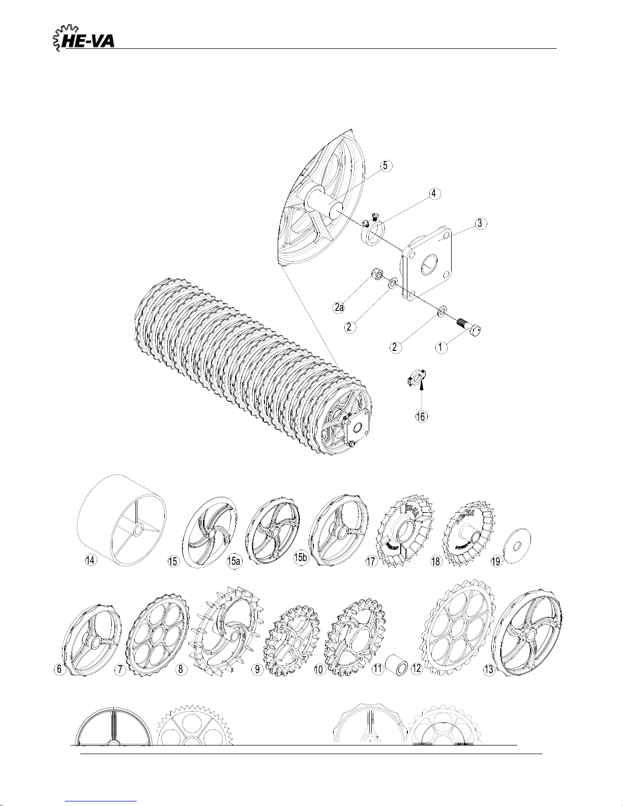
4.7 Roller Block
Aggresive
Lenient
Page 15
Tip Roller 4,5 / 5,4 / 6,3m (excl. 6,3 m w/620mm cambridge) 10/07-2018
15
Pos.
Art. No.
Designation
4,5 m
5,4 m
6,3 m
1
0235830
Bolt M16x55
24
24
24
2
0272290
Facetted disc ø16
48
48
48
2a
0264090
Self-locking nut M16
24
24
24
3
690140812
Bearing UCF 309, ø45, 4-hole, ø50 axle
6 6 6
3
690140813
Bearing UCF 211, ø55, 4-hole, ø60 axle
6 6 6
4
630552300
Stop ring with bolt, ø50 axle
3 3 3
4
671040400
Stop ring with bolt, ø60 axle
3 3 3
4a
691040045
Set screw for bearing UCF 309, M10x1.25 L=12
6 6 6
4a
691040046
Set screw for bearing UCF 211, M10x1.0 L=10
6 6 6
5
678541736
Axle for centre + side sections Ø50 ST70 L=1736
3 0 0
5
678542066
Axle for centre + side sections Ø50 ST70 L=2066
0 3 0
5
678542370
Axle for centre + side sections Ø50 CrNi L=2370
0 0 3
5
678661736
Axle for centre + side sections Ø60 ST70 L=1736
3 0 0
5
678662063
Axle for centre + side sections Ø60 ST70 L=2063
0 3 0
5
678662370
Axle for centre + side sections Ø60 ST70 L=2370
0 0 3
6
690150039
Cambridge plain ring Ø450 (Ø60) Lenient
45
54
63
7
690150040
Cambridge breaker ring Ø450 (Ø60) Lenient
42
51
60
6
690150024
Cambridge plain ring Ø510 (Ø60) Aggresive
45
54
63
6
690150030
Cambridge plain ring Ø510 (Ø60) Lenient
45
54
63
7
690150025
Cambridge breaker ring Ø510 (Ø60) Aggresive
42
51
60
7
690150032
Cambridge breaker ring Ø510 (Ø60) Lenient
42
51
60
8
690150007
Cam ring 22" (Ø50)
30
36
42
9
690150034
Crosskill ring ø485 mm (Ø60)
24
27
33
9
690150074
Cross-killring Ø550 mm (Ø60)
24
27
10
690150011
Loose Crosskill ring ø530 mm
21
27
30
10
690150075
Løs cross-killring Ø600 mm
21
27
11
690150076
Hub for loose Crosskill ring Ø60
21
27
30
12
690150059
Breaker ring 24" Ø620 after machin no. 342089
42
51 0 13
690150049
Plain ring 24" Ø620 after machin no. 342089
45
54
0
12
690150102
Breaker ring Ø560
42
51
13
690150101
Plain ring Ø560
45
54
14
690150028
Plainring Ø505 (ø60)
15
18
21
15
690150013
Corrugated ring Ø500 (ø60) END 1. april 2011
90
108
126
15a
690150050
2D Corrugated ring 600 mm 5 spokes New from 1. april 2011
57
69
15a
690150109
2D Corrugated ring 550mm 5 spokes
57
69
15b
690150087
2D Corrugated ring 500 mm 3 spokes New from 1. april 2011
57
69
78
16
690150091
Adjustment shim 25mm, complete set with bolts
16
690150090
Adjustment shim 15mm, complete set with bolts
16
690150099
Adjustment shim 20mm, complete set with bolts
Page 16
Tip Roller 4,5 / 5,4 / 6,3m (excl. 6,3 m w/620mm cambridge) 10/07-2018
16
17
690150063
Star ring Ø500, Center Ø135
45
54
63
18
690150064
Star ring Ø450 w/neck Ø60
45
54
63
17
690150065
Star ring Ø600, Center Ø135
45
54 18
690150066
Star ring Ø550 w/neck Ø60
45
54 19
690150112
Round plate Ø235 for mounting star rings
3 3 3
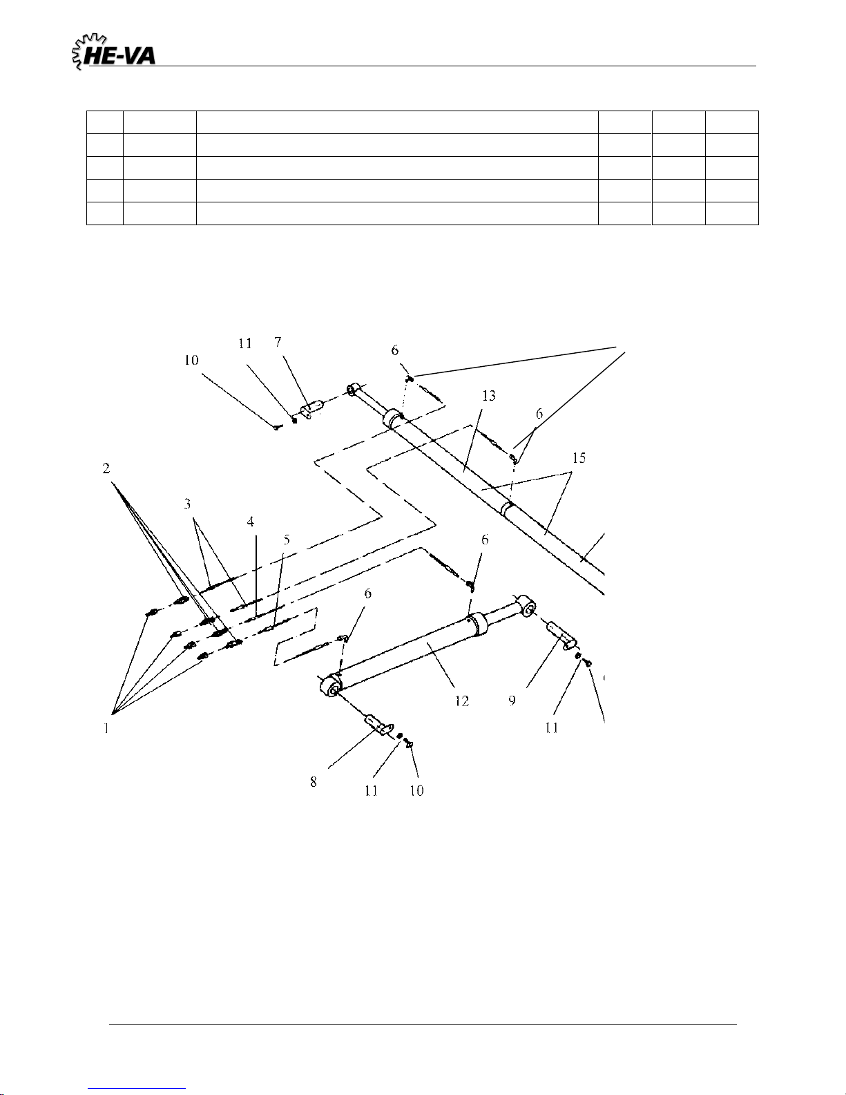
4.8 Hydraulic Roller
16
Page 17
Tip Roller 4,5 / 5,4 / 6,3m (excl. 6,3 m w/620mm cambridge) 10/07-2018
17
Pos.
Art. No.
Designation
4.5 m
5.4 m
6.3 m
1
690203001
Quick-coupling ½" male
4 4 4
1a
690119202
Tie strap blue
2 2 2
1b
690119203
Tie strap red
2 2 2
2
690203003
Screw-in straight GA10LK ½"
4 4 4 3 690201004
Hydraulic hose 1/4" L=4950 mm
2 2 0
3
690201034
Hydraulic hose 1/4" L=5500 mm
0 0 2
4
690201006
Hydraulic hose 1/4" L=3800 mm
1 1 0
4
690201029
Hydraulic hose 1/4" L=4300 mm
0 0 1
5
690201005
Hydraulic hose 1/4" L=3300 mm
1 1 0 5 690201007
Hydraulic hose 1/4" L=3700 mm
0 0 1 6 690203006
Screw-in angle VA10LK 3/8"
4 4 4 7 69430090G
Pin ø30 L=90
2 2 2 8 69530135G
Pin ø30 L=135
1 1 1 9 69430175G
Pin ø30 L=175
1 1 1
10
690101101
Bolt M12x25
4 4 4
11
630532600
Locking bush for pin head
4 4 4
12
690200050
Tip cylinder 80/40x500 mm
1 1 0
12
690200350
Tip cylinder 90/40x500mm v/Ø620mm Cambridgeringe
after machin no. 342089
1
12
690200120
Tip cylinder 80/40x600 mm
0 0 1
12e
690200143
Packing set 80/40
- - -
13
690200010
Wing cylinder for weight balancing cylinder 60/30x500
1 1 0
13e
690200076
Packing set 60/30
- - -
13
690200030
Wing cylinder for weight balancing cylinder 70/40x600
0 0 1
13e
690200068
Packing set 70/40
- - -
14
630727000
Spring unit for weight balancing cylinder
1 1 0
14
630757000
Spring unit for weight balancing cylinder
0 1 1
15
630727010
Weight balancing cylinder
1 1 0
15
630757010
Weight balancing cylinder
0 0 1
16
690207901
Restrictor 1 mm
2 2 2
Page 18
Tip Roller 4,5 / 5,4 / 6,3m (excl. 6,3 m w/620mm cambridge) 10/07-2018
18
5. Spring-Board
The Spring-Board requires a double-acting oil outlet on the tractor. The tine angle is hydraulically
controlled from the driver's cap, with manual depth control. The tines work independently of each other,
but can be coupled together by means of a transverse locking fittings (accessories), if a greater levelling
output is required. The replacement is done easily and without use of any tools.
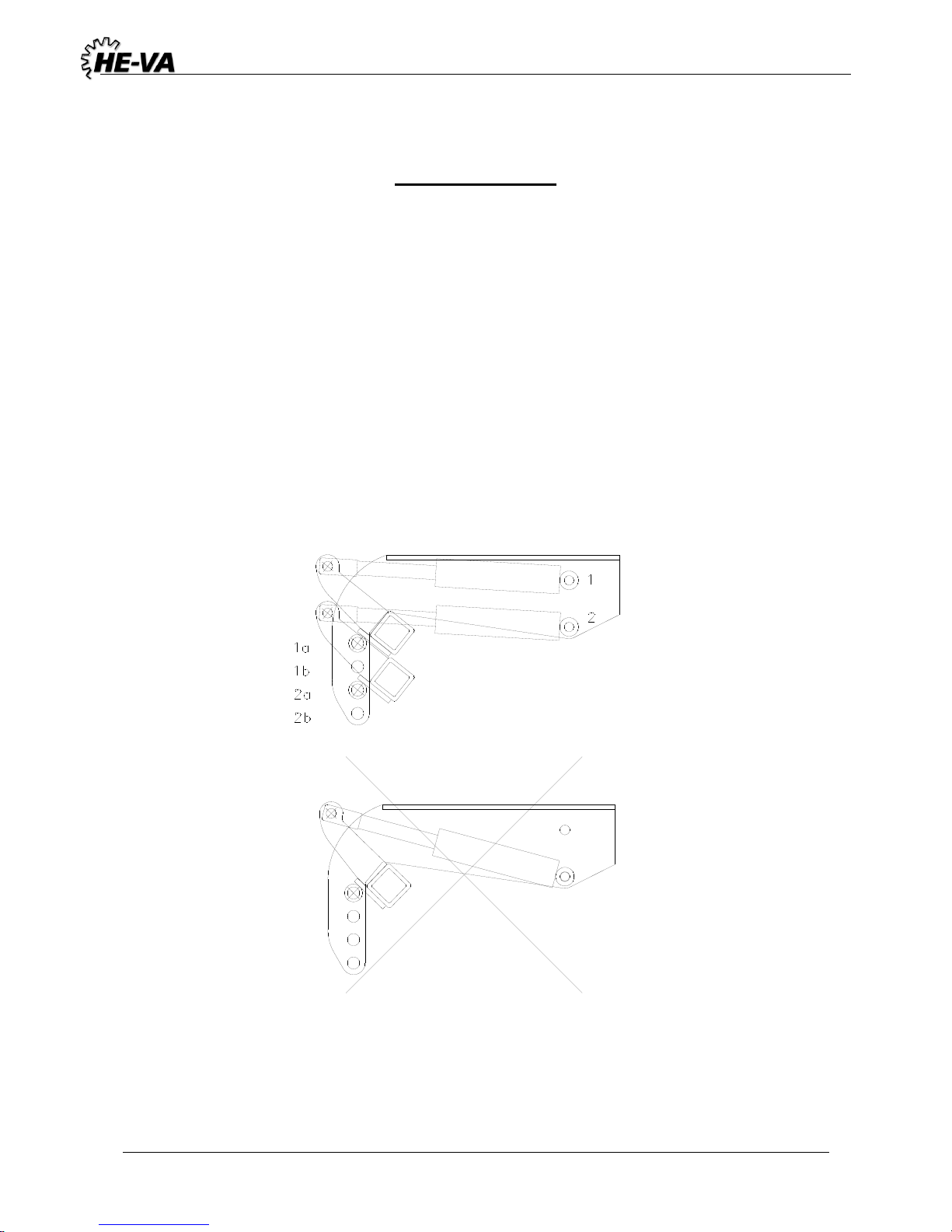
5.1 Installation of Cylinder on the Spring-Board
The hydraulic cylinders are installed as shown below. It is important that they are installed correctly in
order to achieve the proper force of the cylinders.
The ring type determines whether the cylinders must be installed in hole 1 or hole 2. If the machine is
with 450 or 550 mm rings, the cylinders must be installed in hole 1 and hole 1a or 1b. If the machine is
with 620 mm rings, the cylinders must be installed in hole 2 and hole 2a or 2b.
Page 19
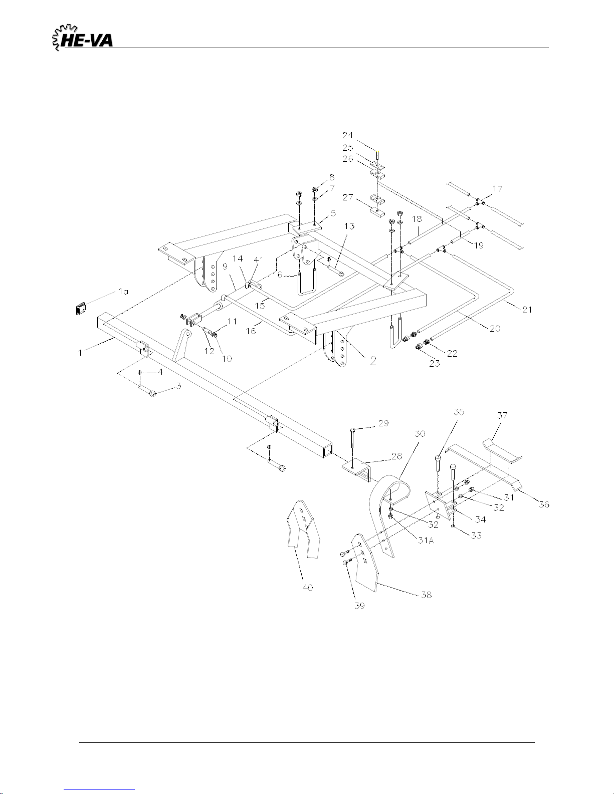
Tip Roller 4,5 / 5,4 / 6,3m (excl. 6,3 m w/620mm cambridge) 10/07-2018
19
5.2 Spring-Board, Center Section
Page 20
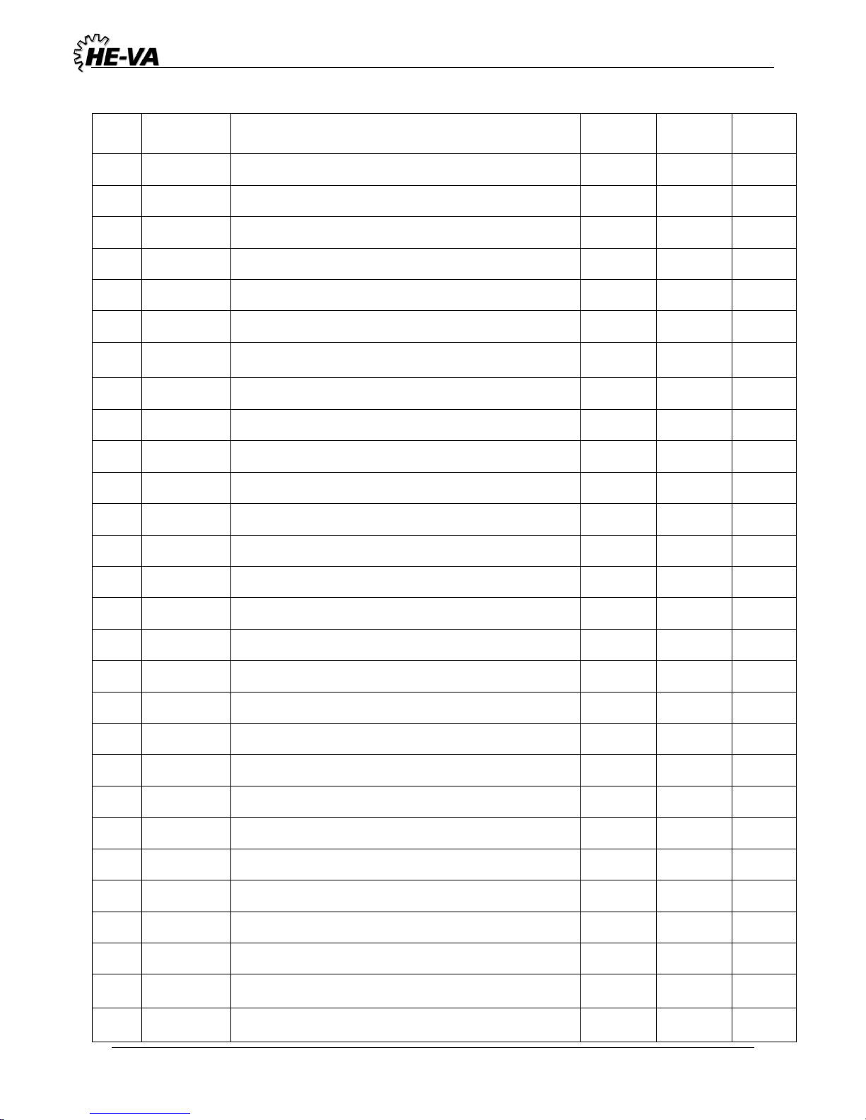
Tip Roller 4,5 / 5,4 / 6,3m (excl. 6,3 m w/620mm cambridge) 10/07-2018
20
Pos.
Art. No.
Designation
Qty.
Qty.
Qty.
4.5 m
5.4 m
6.3 m
1
633033020
Box section for tines
1 0 0
1
633043020
Box section for tines
0 1 0
1
633053020
Box section for tines
0 0 1
1A
690109202
Plast plug
2 2 2
2
633031000
Suspension for centre section
1 0 0
2
635041000
Suspension for centre section
0 1 0
2
635041005
Suspension for centre section
after machin no. 342089
1
2
633051000
Suspension for centre section
0 0 1
3
69525087F
Pin Ø25 L=87
2 2 2
4
0378200
Ring splitter-pin Ø4,5
3 3 3
5
670861100
Flange 2 2
2
6
690110101
U-Bolt M16x100x100x100
2 2 2
7
0272900
Disc Ø16
4 4 4
8
0264090
Nut M16
4 4 4
9
690200160
Cylinder 50/30x155
1 1 1
9e
690200045
Packing set 50/30 mm
- - -
10
691372020
Locking ring U 20 A2 Din 471
2 2 2
11
690115010
Washer Ø20/Ø28x1mm
2 2 2
12
69520046D
Pin Ø20 L=46
1 1 1
13
69520087F
Pin Ø20 L=87
1 1 1
14
690203006
Screw-in angle VA10LK 3/8"
2 2 2
15
690201015
Hydraulic hose 1/4" L=710
1 0 0
15
690201051
Hydraulic hose 1/4" L=250
0 1 1
16
690201015
Hydraulic hose 1/4" L=710
1 0 0
16
690201059
Hydraulic hose 1/4" L=350
0 1 1
17
690203015
Fastener T10
4 4 4
18
690201040
Hydraulic hose 1/4" L=1480
1 0 0
18
690201032
Hydraulic hose 1/4" L=1130
0 1 0
Page 21
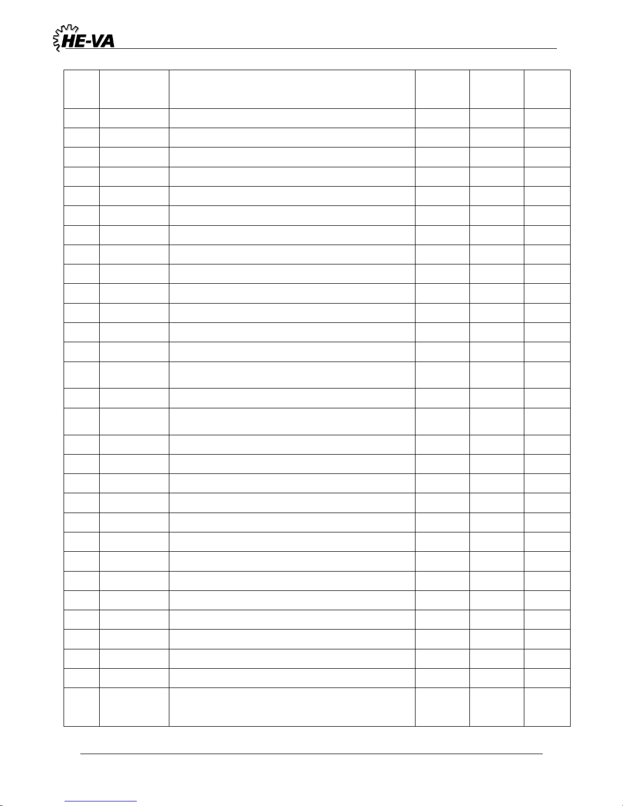
Tip Roller 4,5 / 5,4 / 6,3m (excl. 6,3 m w/620mm cambridge) 10/07-2018
21
Pos.
Art. No.
Designation
Qty.
Qty.
Qty.
4.5 m
5.4 m
6,3 m
18
690201032
Hydraulic hose 1/4" L=1130
0 0 1
19
690201040
Hydraulic hose 1/4" L=1480
1 0 0
19
690201053
Hydraulic hose 1/4" L=1260
0 1 0
19
690201053
Hydraulic hose 1/4" L=1260
0 0 1
20
690201060
Hydraulic hose 1/4" L=3000
1 0 0
20
690201044
Hydraulic hose 1/4" L=3460
0 1 0
20
690201038
Hydraulic hose 1/4" L=4000
0 0 1
21
690201060
Hydraulic hose 1/4" L=3000
1 0 0
21
690201005
Hydraulic hose 1/4" L=3300
0 1 0
21
690201006
Hydraulic hose 1/4" L=3800
0 0 1
22
690203003
½" screw-joint for quick-coupling (male)
2 2 2
23
690203001
Quick-coupling (male) ½"
2 2 2
24
690210213
Screw for double tube support (ø14, ø15, ø16, ø18)
5 5 5
25
690210211
Top plate for double tube support (ø14, ø15, ø16,
ø18) 5 5
5
26
690210210
Tube support double ø14/ø14
10
10
10
27
690210212
Welding plate for double tube support (ø14, ø15,
ø16, ø18)
5 5 5
28
633052200
Tine support
6 8 8
29
690103098
Bolt M12x110
6 8 8
30
633052050
Tine (10x80)
6 8 8
30a
633052000
Tine complete, with flat tine point
6 8 8
31
0264070
Self-locking nut M12
18
24
24
32
0272270
Disc ø12
18
24
24
33
0431975
Locking ring 30xø3
12
16
16
34
633055500
Tine fittings for locking system
6 8 8
35
69512040K
Pin Ø12,5 x 40
12
16
16
36
633055710
Long locking rod for locking system
10
14
14
37
633055700
Short locking rod fr locking system
2 2 2
38
633052100
Tine point (8x150)
6 8 8
39
0248670
Bolt M12 x 45
12
16
16
40
633052150
Tine point (crush breaker)
6 8 8
41
690207901
Restrictor 1 mm
1 1 1
Page 22
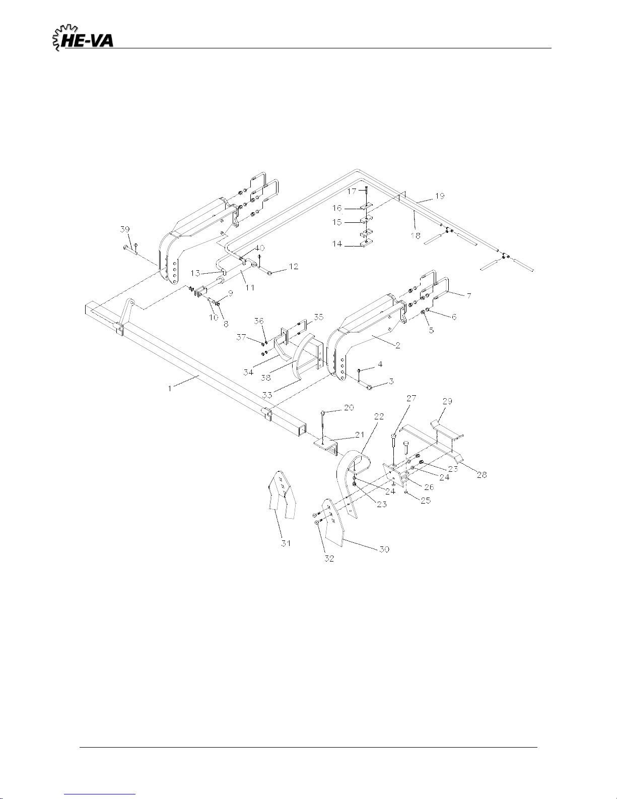
Tip Roller 4,5 / 5,4 / 6,3m (excl. 6,3 m w/620mm cambridge) 10/07-2018
22
5.3 Spring-Board – Left Side Section
Page 23
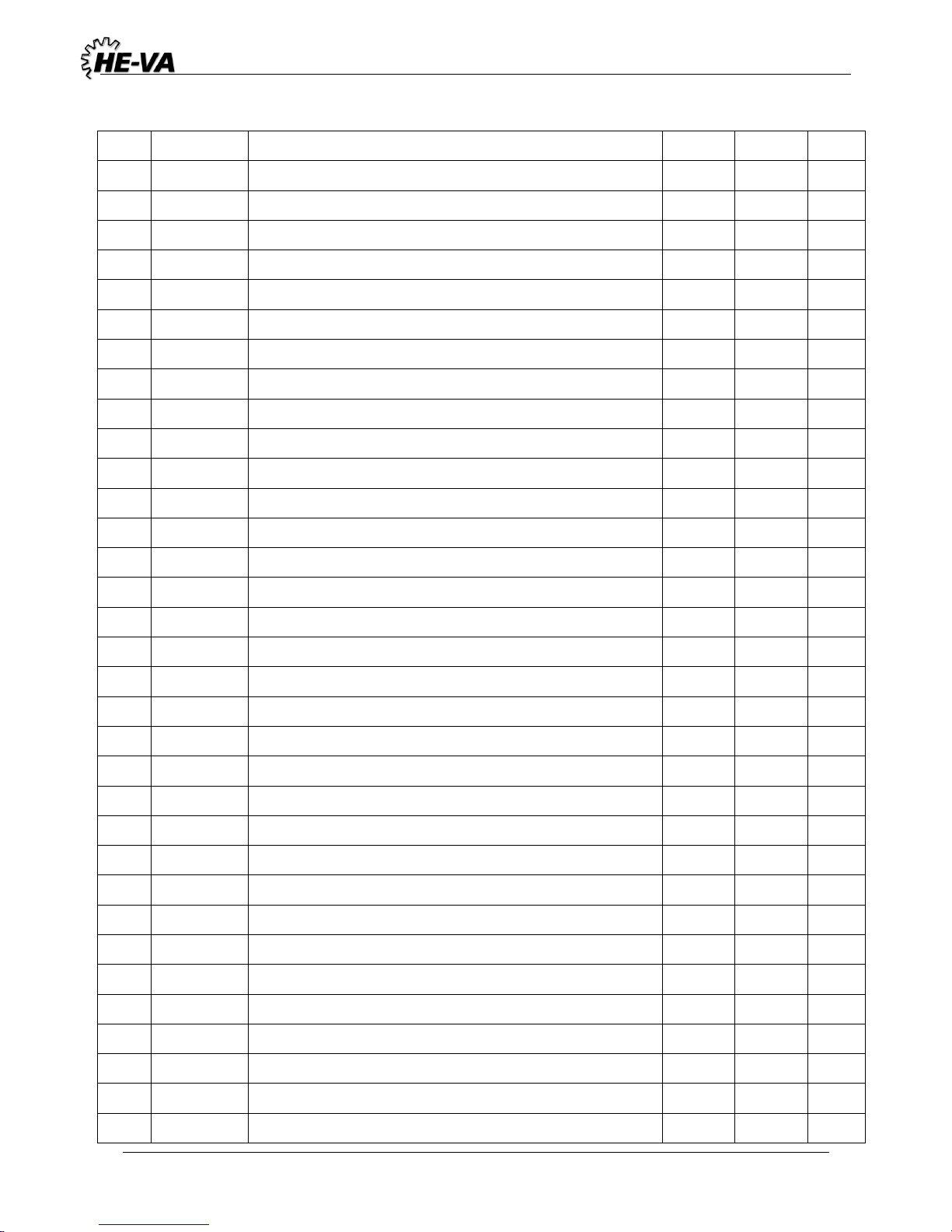
Tip Roller 4,5 / 5,4 / 6,3m (excl. 6,3 m w/620mm cambridge) 10/07-2018
23
Pos.
Art. No.
Designation
4.5 m
5.4 m
6.3 m
1
633033010
Box section for tines (right)
1 0 0 1 633033030
Box section for tines (left)
1 0 0 1 633043010
Box section for tines (right)
0 1 0 1 633043030
Box section for tines (left)
0 1 0 1 635053010
Box section for tines (right)
0 0 1 1 635053030
Box section for tines (left)
0 0 1
2
633054500
Suspension for side section
4 4 4
2
633054520
Suspension for side section (after 1th June 2010)
4 4 4
3
69525095F
Pin Ø25 L=95
1 1 1
4
690134001
Ring splitter-pin Ø4,5
6 6 6 5 690113008
Self-locking nut M16
16
16
16
5
690113016
Self-locking nut M18 (after 1th June 2010)
16
16
16 6 0272900
Disc Ø16
16
16
16
6
690117015
Disc Ø18 (after 1th June 2010)
16
16
16
7
690110402
U-Bolt M16x160x80x160 mm
8 8 8 7 690110405
U-Bolt M18x160x80x160 mm (after 1th June 2010)
8 8 8 8 691372020
Locking ring U 20 A2 Din 471
4 4 4 9 690115010
Washer Ø20/Ø28x1mm
4 4 4
10
69520046D
Pin Ø20 L=46
2 2 2
11
690200160
Cylinder 50/30 x 155
2 2 2
11e
690200045
Packing set 50/30 mm
2 2 2
12
69520087F
Pin Ø20 L=87
2 2 2
13
690203006
Screw-in angle VA10LK 3/8"
4 4 4
14
690210212
Welding plate f/double tube support (ø14, ø15, ø16, ø18)
6 6 8
15
690210210
Tube support double ø14/ø14
12
12
16
16
690210211
Top plate for double tube support (ø14, ø15, ø16, ø18)
6 6 8
17
690210213
Screw for double tube support (ø14, ø15, ø16, ø18)
6 6 8
18
690201022
Hydraulikslange 1/4" left side section L= 3140 mm
1 0 0
18
690201005
Hydraulikslange 1/4" right side section L= 3300 mm
1 0 0
18
690201044
Hydraulikslange 1/4" left side section L= 3460 mm
0 1 0
18
690201048
Hydraulikslange 1/4" right side section L= 3610mm
0 1 0
18
690201048
Hydraulikslange 1/4" left side section L= 3610 mm
0 0 1
18
690201006
Hydraulikslange 1/4" right side section L= 3800 mm
0 0 1
Page 24
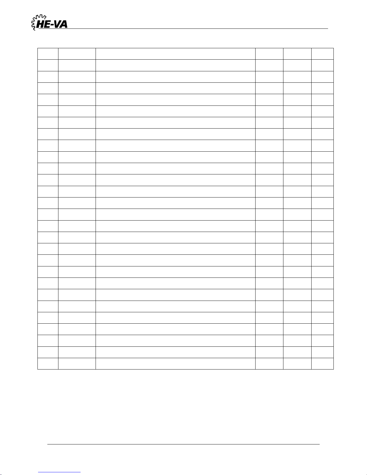
Tip Roller 4,5 / 5,4 / 6,3m (excl. 6,3 m w/620mm cambridge) 10/07-2018
24
19
690201060
Hydraulikslange 1/4" left side section L= 3000 mm
1 0 0
19
690201060
Hydraulikslange 1/4" right side section L= 3000 mm
1 0 0
19
690201022
Hydraulikslange 1/4" left side section L= 3140 mm
0 1 0
19
690201005
Hydraulikslange 1/4" right side section L= 3300 mm
0 1 0
19
690201044
Hydraulikslange 1/4" left side section L= 3460 mm
0 0 1
19
690201048
Hydraulikslange 1/4" right side section L= 3610 mm
0 0 1
20
690103098
Bolt M12x110
12
14
16
21
633052200
Tine support
12
14
16
22
633052050
Tine (10x80)
12
14
16
22a
633052000
Tine complete
12
14
16
23
0264070
Selflocking nut M12
36
42
48
24
0272270
Disc Ø12
36
42
48
25
0431975
Locking ring 30xø3
24
28
32
26
633055500
Tine fitting for locking system
12
14
16
27
69512040K
Pin ø12.5x40
24
28
32
28
633055710
Long locking nut for locking system
10
12
14
29
633055700
Short locking nut for locking system
4 4 4
30
633052100
Tine point (8x150)
12
14
16
31
633052150
Tine point (crush breaker)
12
14
16
32
0248670
Bolt M12x45
24
28
32
33
635151000
Scale for depth control
1 1 1
34
635152000
Indicator for depth control
1 1 1
35
690110020
U-bolt M10x70x70x70 mm
1 1 1
36
0272260
Disc Ø10
2 2 2
37
0264060
Self-locking nut M10
2 2 2
38
698500018
Sticker for scale f/springboard
1 1 1
39
69525087F
Pin ø25 L=87
3 3 3
40
690207901
Restrictor 1mm
2 2 2
Page 25
Tip Roller 4,5 / 5,4 / 6,3m (excl. 6,3 m w/620mm cambridge) 10/07-2018
25
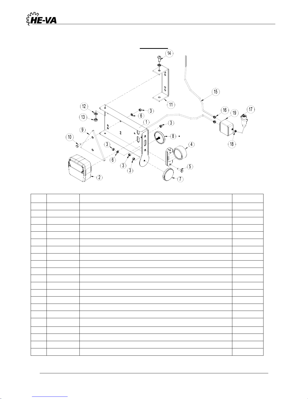
6. Lights
LED Light set
Pos.
Vare nr.
Betegnelse
Antal
1
7357505
Lightbox (L)
1
7357508
Lightbox (R)
1
2
7357504
Rear light
2
3
0264030
Locking nut M5
16
4
7357507
Marking lights (L)
1
7357509
Marking lights (R)
1
5
0234340
Bolt M5x25
4
6
0272240
Facet plate Ø5
8
7
0656240
Reflex, yellow
2
8
0656250
Reflex, white
2
9
692160017
Reflex, red
2
10
0234330
Bolt M6x20
4
11
7357516
Bracket
2
12
0272250
Facetplate Ø8
16
13
0264050
Locking nut M8
8
14
0234750
Bolt M8x20
4
15
690160080
Cable 5 x 1mm² (Inform about lenght by ordering sparepart)
16
7357545
Rutaseal nipple M20 8-12mm Grey RAL7001
2
17
690160070
Plug 7 poles DIN 72 577 – ISO 1724
1
18
7357546
Rubberbushing Nr. 38A Ø10/3 black
1
19
0520492
Junction box 105x105x60
1
Note:
Check number and measurements of all cables before ordering the spare parts.
Page 26
Tip Roller 4,5 / 5,4 / 6,3m (excl. 6,3 m w/620mm cambridge) 10/07-2018
26
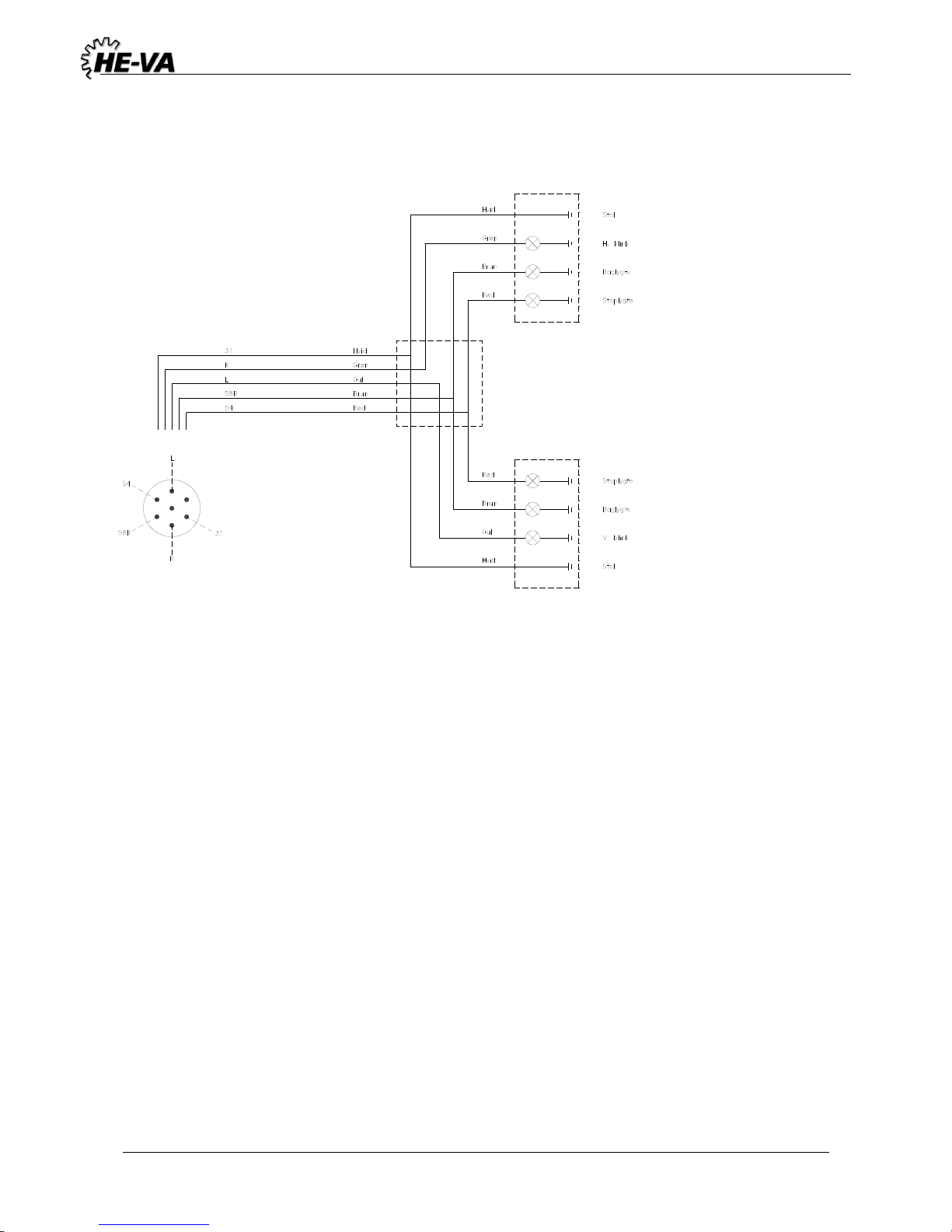
Lighting set: El. diagram
Page 27
Tip Roller 4,5 / 5,4 / 6,3m (excl. 6,3 m w/620mm cambridge) 10/07-2018
27
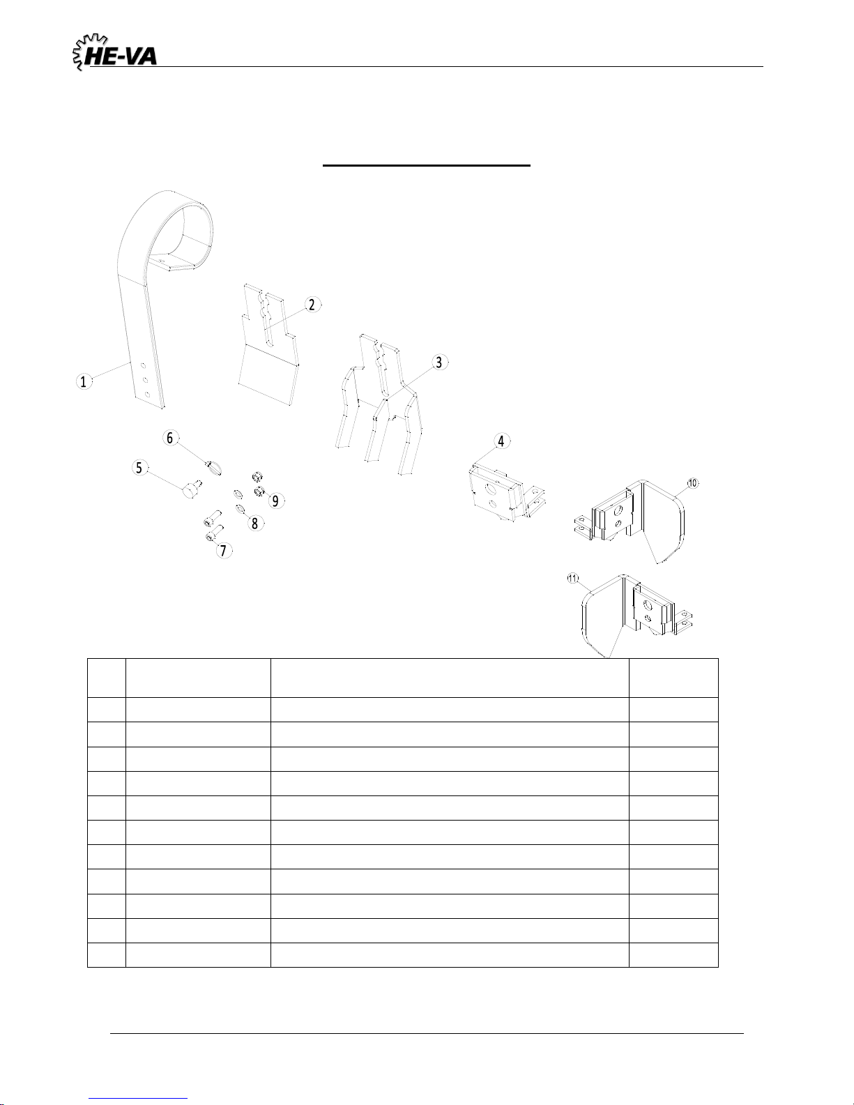
7. Easy Change System
Pos.
Item no.
Designation
Antal
1
0422145
Spring-Board tine
1 2 1170388
Flat wearing point - Easy Change
1
3
1170410
Slicing plate point w/3 tines – Easy-Change
1 4 1170389
Easy-Change bracket for transverse locking system
1
5
1170391
Locking pin
1 6 0378200
Ring split Ø4,5 mm
1 7 0227842
Insex DIN912 M12x35mm Fzb 8.8
2
8
0272270
Facet plate 12mm
2
9
0264070
Self-locking nut M12
2
10
1170806
Edge equipment, left
1
11
1170805
Edge equipment, right
1
Page 28
Subject to design modifications without prior notice.
 Loading...