

Page 1
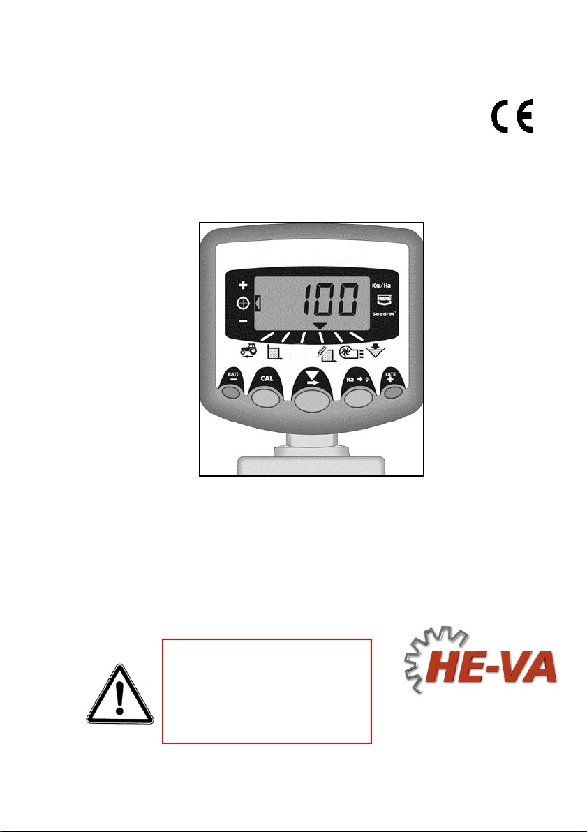
HE-VA Auto-Controller
AC-LITE
Installation, Calibration and
Operation
Software Reference WZ704-000 rev.15
N. A. Christensensvej 34
DK-7900 Nykøbing Mors
Tel: +45 9772 4288
Fax:+45 9772 2112
www.he-va.com
Important:
Before using the machine,
please study the Operating
Instructions thoroughly to
ensure that you are familiar
with the safety instructions.
User Guide
Electro-Magnetic Compatibility (EMC)
This product complies with
Council Directive 89/336/EEC
when installed and used in accordance
with the relevant instructions.
1
Page 2

HE-VA Auto-Controller AC-Lite - May 2016
1. Overview ____________________________________ 4
1.1 Programming Modes ..................................................................................... 4
2. Installation __________________________________ 5
2.1 The Head Unit ............................................................................................... 6
2.2 The ‘Tractor Terminator’ Assembly ................................................................ 7
2.3 Power supply ................................................................................................. 8
2.4 Radar sensor ................................................................................................. 8
2.5 Cutout switch ................................................................................................. 9
3. Normal Operating Mode ______________________ 10
3.1 Operating Summary .................................................................................... 10
3.2 Power On/Off ............................................................................................... 11
3.3 Work Status Indicator .................................................................................. 11
3.4 Starting and Stopping the Seeding .............................................................. 11
3.5 Pre-start function ......................................................................................... 11
3.6 Cutout Alarm................................................................................................ 12
3.7 Simulated Speed ......................................................................................... 12
3.8 Application Rate – kg/ha or seeds/m² .......................................................... 12
4. Forward Speed Display _______________________ 13
4.1 View Forward Speed ................................................................................... 13
4.2 Minimum Speed Alarm ................................................................................ 13
4.3 Speed Sensor Calibration ............................................................................ 13
4.4 ‘Autocal’ Speed Calibration ......................................................................... 14
5. Area Display ________________________________ 15
5.1 View Area Totals ......................................................................................... 15
5.2 Zero Area Total ............................................................................................ 15
5.3 Set Implement Width ................................................................................... 16
6. Drilling Rate Functions _______________________ 17
6.1 View Drilling Rate ........................................................................................ 17
6.2 Adjusting the Drilling Rate ........................................................................... 17
6.3 Drilling Rate Indicator .................................................................................. 17
6.4 Changing the Target Rate ........................................................................... 18
6.5 Product Calibration ...................................................................................... 19
6.6 Set % Step for Rate Offset .......................................................................... 20
2
Page 3

HE-VA Auto-Controller AC-Lite - May 2016
7. Hopper level Alarm ___________________________ 21
7.1 Feed roll monitoring………………………………………………………………21
8. Fan Speed / Speed Alarms ____________________ 21
Display Fan Speed ................................................................................................. 21
Fan Speed Alarms .................................................................................................. 21
Set Low Fan Speed Alarm ...................................................................................... 22
9. Programme Functions and Fault Diagnosis ______ 23
9.1 Programme (CAL) Modes 1 – 5 ................................................................... 23
9.2 Fault Diagnosis ............................................................................................ 24
10. Calibration Record ___________________________ 25
3
Page 4

HE-VA Auto-Controller AC-Lite - May 2016
1. Overview
The HE-VA Auto-Controller enables fully automatic control of the seed rate of
HE-VA Multi-Seeder.
The HE-VA Auto-Controller automatically maintains a preset application rate as
forward speed varies, with on-the-go adjustment of rate.
The instrument measures and indicates:
Forward Speed
Part Area and Total Area worked
Seed Application Rate (kg/ha)
Low Hopper Level
There are also audible and display alarms for,
Minimum / maximum forward speed (beyond which the programmed seed rate
cannot be maintained).
Feed motor stopped (no feedback)
Feed motor stalled
The head unit is powered on and off via a toggle switch on the rear of the instrument.
A pushbutton switch in the cab is used to manually switch the feed motor on and off.
The feed motor is also switched on and off automatically via the implement-mounted
cutout finger switch as the implement is raised and lowered.
Area totals and all calibration data are automatically stored in memory when the
instrument is powered off.
The system must be initially calibrated for the seed being applied. Seed calibration is
very simple to undertake via a priming switch provided on the junction box fitted on the
Multi-Seeder.
1.1 Programming Modes
There are 5 programming modes with various calibration factors and default settings.
Access to the programming modes is required for some settings that may be changed
as part of the normal operating procedure. Changing these settings is described with
the operation instructions (sections 4,5,6,7 and 8).
Other settings are made on installation and do not normally need to be changed.
These settings are appended to in the back of this manual (section 9). The operator
does not normally need to refer to them.
NOTE: The instrument front panel appearance may be slightly different to that illustrated.
4
Page 5
HE-VA Auto-Controller AC-Lite - May 2016
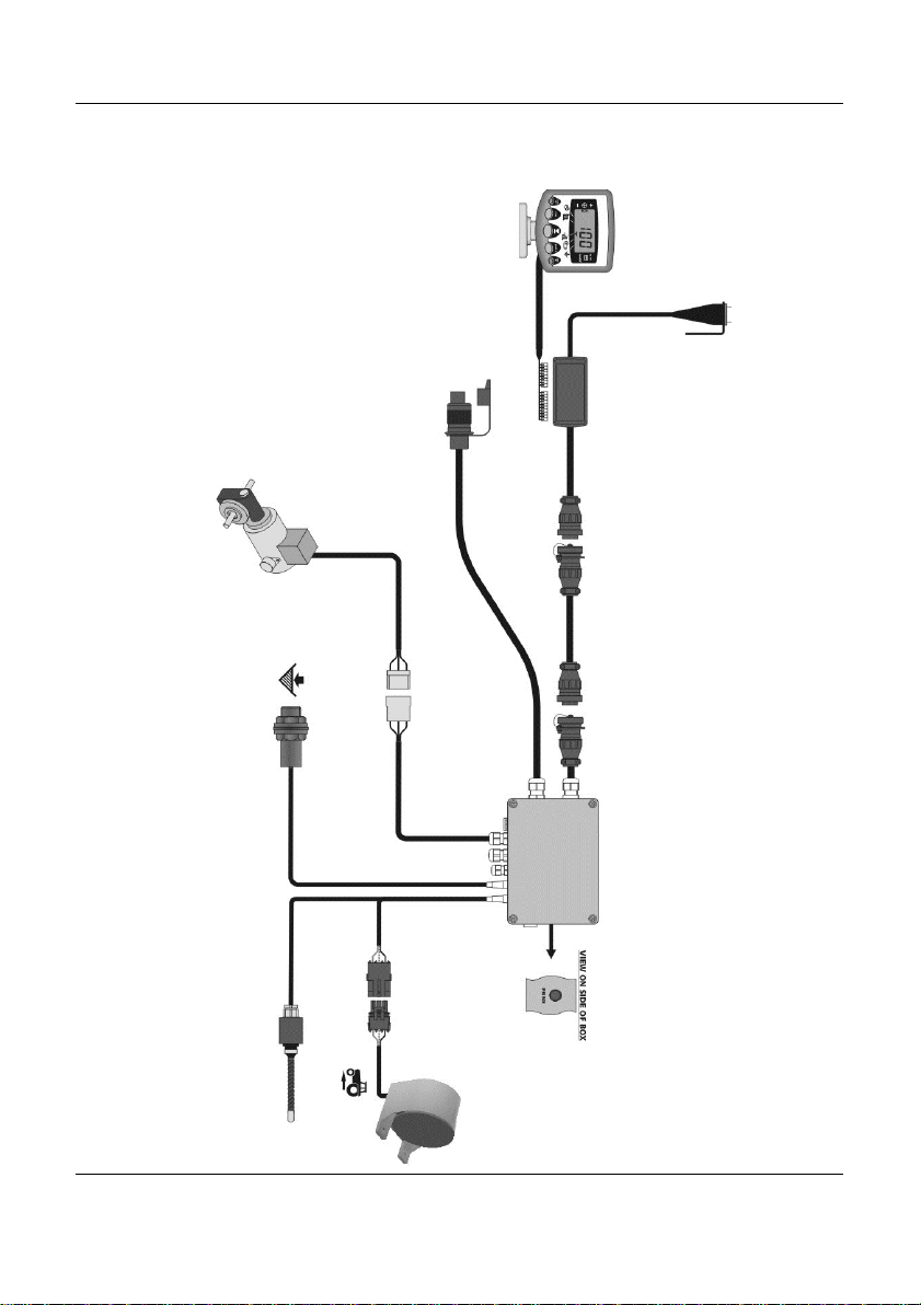
Head Unit
Manual
Cutout
Switch
Power supply
Junction Box
Assy
View on side of J/Box
- ‘Prime’ button
Automatic
Cutout Switch
Radar Sensor
TJ237
(shown as fitted on Multi-Seeder, but
can be fitted on tractor and wired into
Tractor Terminator Box)
Hopper Level
sensor
Feed Motor
Tractor Terminator
Assy
Extension cable
2. Installation
Figure 1
5
Page 6
HE-VA Auto-Controller AC-Lite - May 2016
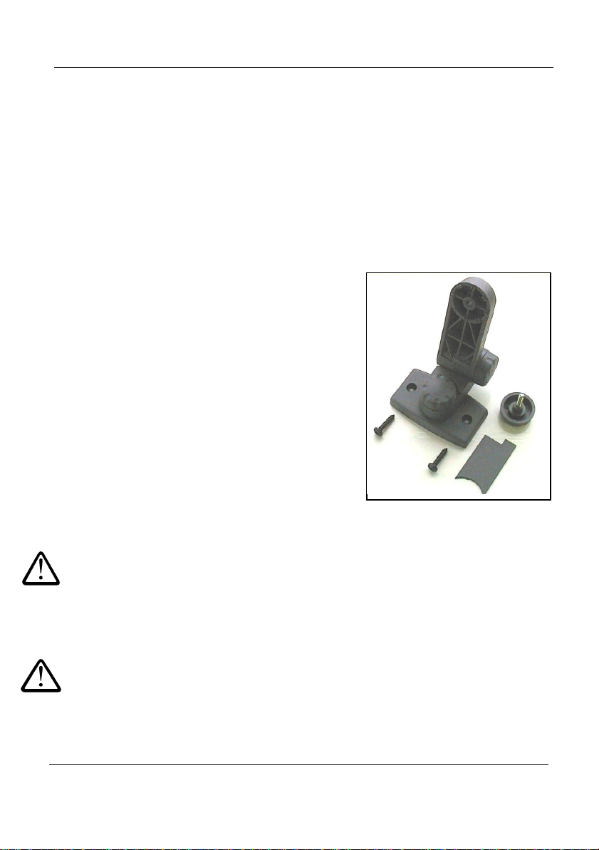
Figure 2 : Head Unit Mounting Kit
2.1 The Head Unit
Confirm with the operator on where to mount the head unit in the cab. It must not
restrict the view out of the cab, nor impede the use of the controls. The head unit is
fitted with a 1-metre flying lead terminating with an 8/10-way IDC type connector, ready
for connection into the "Terminator" junction box.
The head unit is supplied with mounting kit ref: TJ235 comprising the following parts
(fig. 2):
1 Long Bracket
1 Short Bracket
3 Clamping Knobs
1 Cover Plate
1 Mounting Plate
2 Self Tapping Screws
1. Snap the cover plate into the recess of the long
bracket (it only fits one way).
2. The instrument mount is designed to offer maximum
flexibility in positioning the head unit, either from the
right hand side of the cab, from the dashboard or
from an overhead position.
3. Assemble the two brackets, and mounting plate with
clamping knobs, and attach to the head unit.
NOTE: Either the long or short bracket can be
attached to the head unit, whichever gives the
most suitable orientation.
Having established the orientation for the
bracket, fix the mounting plate to the cab
with the self-tapping screws provided.
Do not drill into a ROPS or FOPS frame.
If you are fixing the mounting plate to plastic e.g. the dashboard or other cab moulding,
it is recommended to use M4 screws with mudwing washers to strengthen the
mounting point.
Do not attempt to adjust the mounting bracket assembly without first
slackening off the clamping knobs sufficiently. You will only succeed in
damaging the bracket otherwise.
6
Page 7
HE-VA Auto-Controller AC-Lite - May 2016
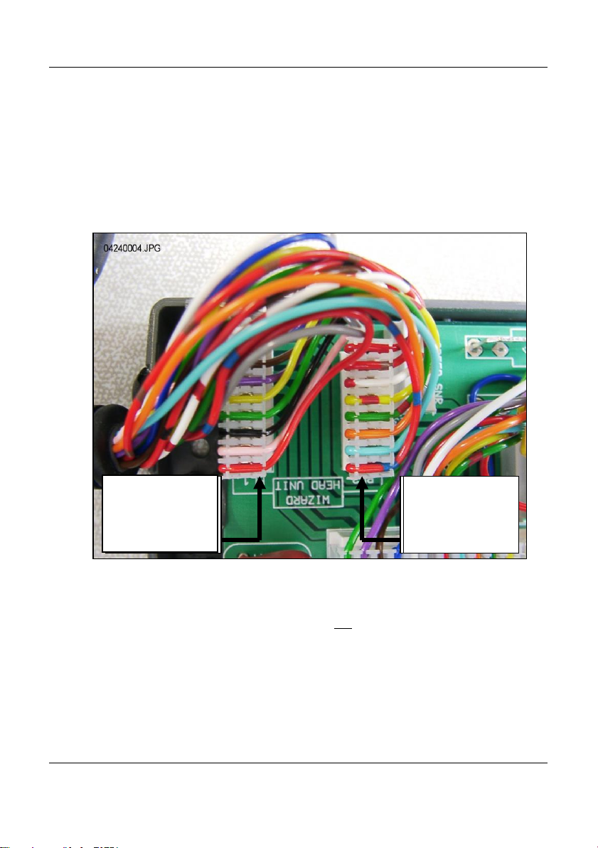
10-way connector
to PL1
(RED wire)
8-way connector
to PL2
(RED/BLUE wire)
2.2 The ‘Tractor Terminator’ Assembly
Mount the pushbutton Cutout Switch in a convenient position using 2 self-tapping
screws.
Remove the lid of the terminal box by squeezing the sides and connect the head unit
lead as shown in figure 3 below.
The Terminator is not a waterproof enclosure. Locate it where it is afforded protection
from possible water ingress and for neatness e.g. behind a trim panel or console.
Figure 3: Head unit connection
NOTE: The head unit receives its power supply via the junction box (see figure 1).
The power supply terminals in the Terminator are not used.
The circular (CPC) connector trails to the back of the tractor to connect with the 6-
metre extension lead going to the junction box.
7
Page 8
HE-VA Auto-Controller AC-Lite - May 2016
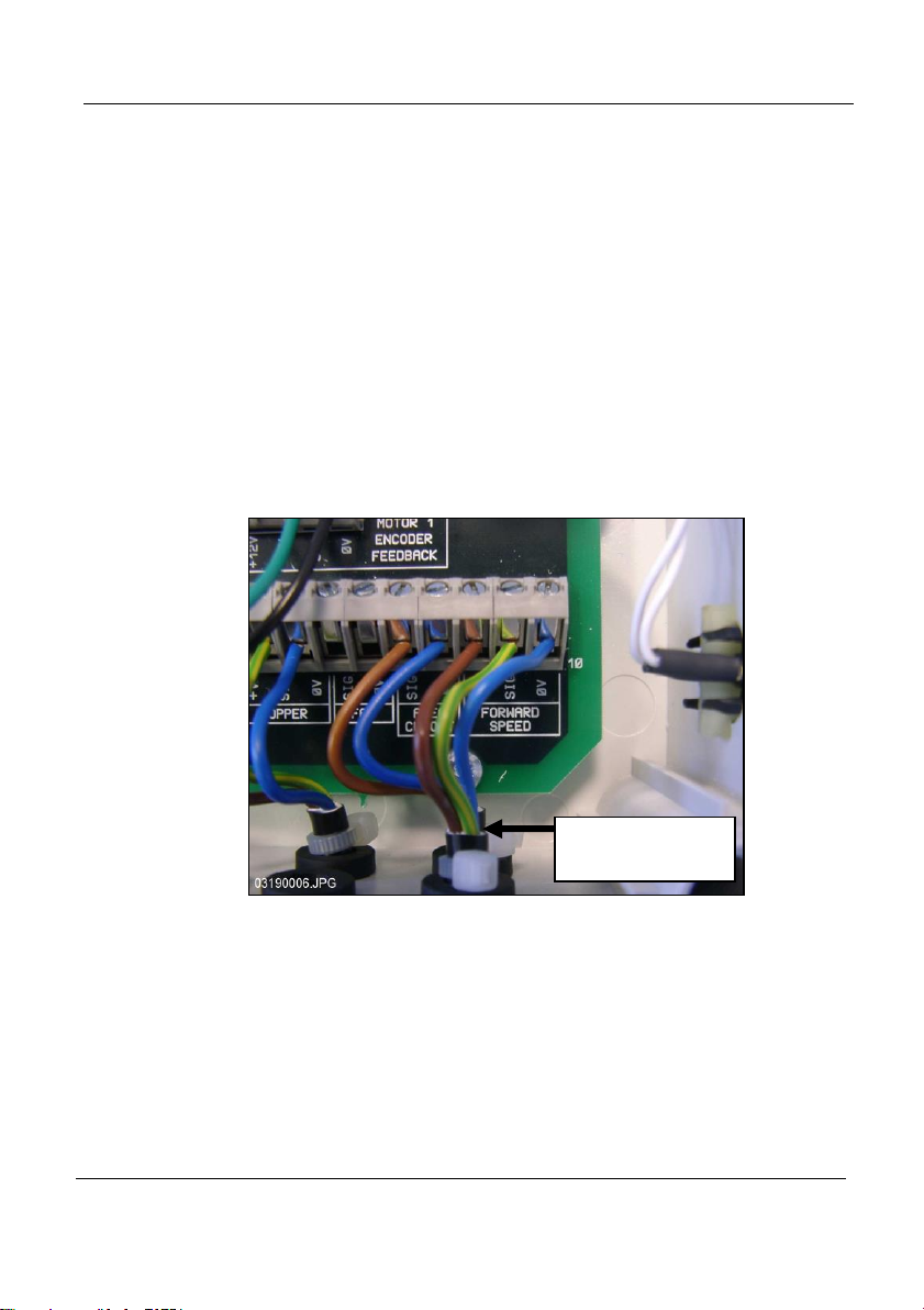
Remove the radar
sensor lead
2.3 Power supply
The system is powered via the three pole plug/connector.
2.4 Radar sensor
The radar sensor may be fitted either to the Multi-Seeder or to the tractor. For fitting
instructions please refer to the separate instruction leaflet ref. S/DC/500-10-511
provided.
Connecting a Multi-Seeder-mounted radar sensor:
Simply connect the radar sensor lead to the lead from the junction box
(3-way connector). Coil any excess lead near the junction box and secure
the lead from the sensor at regular intervals using the cable ties provided.
Connecting a tractor-mounted radar sensor:
Open the junction box and remove the sensor extension lead with the
3-way connector (fig. 4). Plug the hole to prevent water ingress.
Figure 4
Connect the extension lead to the sensor and route back to the Terminator junction
box. Where possible follow the existing wiring loom and secure at regular intervals
using the cable ties provided.
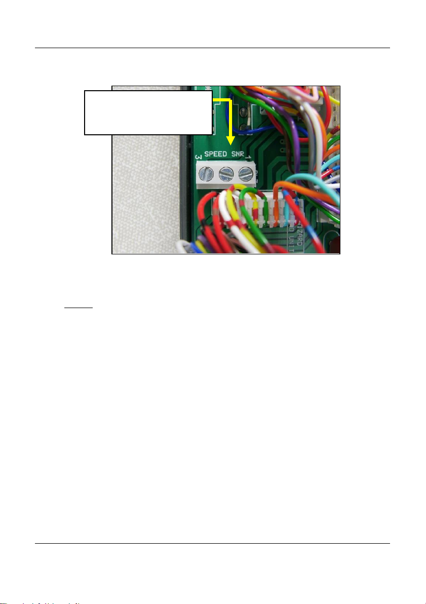
Remove the lid of the terminal box by squeezing the sides, cut off excess cable length
and connect the head unit lead as shown in figure 5.
8
Page 9
HE-VA Auto-Controller AC-Lite - May 2016
1 Brown (+V)
2 Blue (0V)
3 Yellow/Green (Sig)
Figure 5
The default speed sensor calibration factor (SSF) programmed in the head unit =
‘7.78’ (millimeters/pulse). This is theoretically correct for the radar sensor when it is
installed at exactly the specified angle to the ground. Often though, the sensor may
not be exactly at the prescribed angle. It is therefore recommended that to ensure
accurate speed measurement, you check the calibration value by performing an
‘Autocal’ procedure (please refer to section 4.4).
2.5 Cutout switch
The implement-mounted cutout finger switch enables the system to automatically start
and stop operation as the implement is lifted and lowered.
It therefore needs to be mounted in a suitable position to operate as the implement
enters work.
NOTE: For fitting instructions please refer to the separate instruction leaflet
ref. S/DC/500-10-121 provided.
9
Page 10
HE-VA Auto-Controller AC-Lite - May 2016
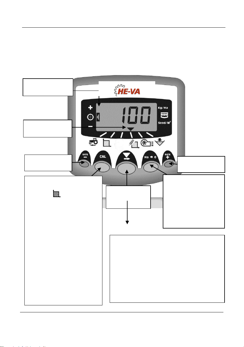
Press to select
the Display
Function
Decrease
Rate
Channel
Indicator
Increase
Rate
EITHER:
1. View Area Total
Select the (Area Total)
channel, then press the CAL
button to switch between Area
Total 1 and Area Total 2.
OR:
2. HOLD continuously for 10
seconds to enter
CAL Mode 1 / CAL Mode 2
(Normal Mode is resumed
when the button is released).
CH Function Units
1 Forward Speed km/h
2 Area Total 1 or 2 ha
3 (No function) -
4 Seed Rate kg/ha
5 (No function) -
6 Hopper level Status These channels have different functions when
the instrument is in Programme (CAL) Mode 1,
2, 3, 4 or 5.
With Area display
selected, press and
HOLD for 5 secs to zero
the selected area total
or,
HOLD whilst powering
on to enter CAL Mode 3
Target rate
Indicator
3. Normal Operating Mode
3.1 Operating Summary
10
Page 11

HE-VA Auto-Controller AC-Lite - May 2016
3.2 Power On/Off
Switch the head unit on via the toggle switch on the rear of the instrument.
The instrument powers up and displays the software version installed e.g. ‘A704’ then
‘Exxx’ then ‘Rxxx’ (software version WZ704-xxx rev.xxx). It then enters its normal
operating mode and displays the forward speed channel.
Select any other channel by pressing the (Channel Select) button once or more.
When the Multi-Seeder is out of work, the instrument will continue to display the
selected channel.
3.3 Work Status Indicator
The indicator is used to indicate the channel to which the information on the
display relates.
It also shows the working status of the Multi-Seeder. If the cursor is flashing then the
Multi-Seeder is out of work, if the cursor is on continuously then the Multi-Seeder is in
work.
3.4 Starting and Stopping the Seeding
The pushbutton switch is used to manually switch the feed motor on and off when the
Multi-Seeder in work*.
The Multi-Seeder is also fitted with a cutout finger switch so that the feed motor starts
and stops automatically when the implement is lowered and raised e.g. on the
headlands.
* The pushbutton switch is not effective when the implement is raised out of work, as it
is overidden by the operation of the cutout switch mounted on the implement.
3.5 Pre-start function
On commencing a bout, the seed motor only starts as you begin moving off. However,
it takes a short period for the seed to traverse the pipe to the coulter. The result is an
unseeded area at the beginning of a bout.
To avoid unseeded patches due to the delay in seed delivery, once positioned and
stationary at the start of the bout, press the outside right switch (“RATE +”). The prestart function is activated and the motor then runs at the calibration speed, so that
seed is planted as you move off.
The pre-start function is timed to run the motor at the calibration speed for a number of
seconds equal to the implement width in metres (e.g. 4m implement = 4 seconds prestart). After this time and the implement is moving forwards, the system reverts to
normal proportional control for the seed rate set. However, if after this time the
implement is still stationary, the motor will automatically switch off.
11
Page 12

HE-VA Auto-Controller AC-Lite - May 2016
NOTE: The default pre-start time is 4 seconds, however it can be changed if required in Cal
Mode 2-Channel 6 (ref. section 9).
3.6 Cutout Alarm
If the forward speed exceeds 2km/h with the Multi-Seeder ‘out of work’, the instrument
will alarm by beeping and flashing ‘C.out’ every 5 seconds. The alarm will continue
until the implement is lowered into work. The forward speed at which this alarm is
displayed can be modified by entering Cal Mode 5 and adjusting the speed on Channel
1. If set to 8.00, then it will not alarm until above 8 km/h.
3.7 Simulated Speed
If there is a problem with the forward speed, or for testing, a ‘Simulated Speed’ can be
used on the instrument. To enable this, disconnect the speed sensor, enter Mode 2
and while on Channel 1, use the + and – buttons to set a simulated speed value. Once
the correct speed is selected, press the Ha->0 button, and the instrument will now use
this speed until it is next powered down.
3.8 Application Rate – kg/ha or seeds/m²
The system can display application rate in either kg/ha or seeds/m². To switch between
the two settings, enter Cal Mode 3 and switch between ‘Rate’ kg/ha or ‘Pop’ seeds/m²
on Channel 1. The Thousand Grain Weight for that seed can then be entered on
Channel 2.
12
Page 13
HE-VA Auto-Controller AC-Lite - May 2016
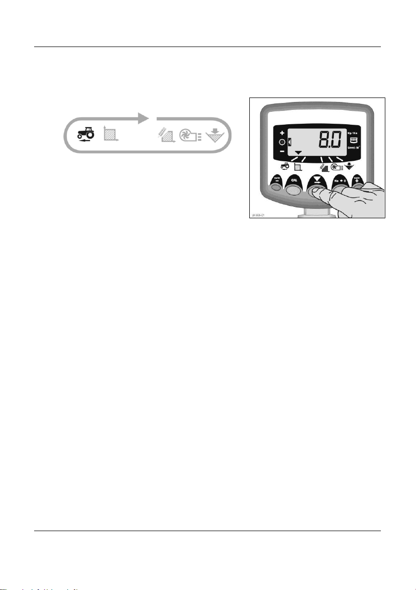
Figure 6: Select Fwd. Speed
4. Forward Speed Display
4.1 View Forward Speed
The forward speed is derived from a radar sensor fitted either to the Multi-Seeder or
the tractor, depending on your particular installation.
The speed is displayed in km/h only.
4.2 Minimum Speed Alarm
As part of product calibration, based on the resulting calibration factor, the instrument
automatically calculates the minimum forward speed below which the system cannot
maintain the programmed seed rate.
With the Multi-Seeder in work, if the forward speed goes below this threshold the
instrument display defaults to channel 1, flashes the actual speed and beeps
continuously. The alarm will continue until speed is increased above the threshold. It
may be cancelled temporarily by selecting another channel but will revert to channel 1
and repeat the alarm after 30 seconds until speed is increased.
NOTE: The application rate will not remain proportional below the minimum speed
threshold. The feed motor cannot run below 3 rpm, resulting in over-application.
4.3 Speed Sensor Calibration
The forward speed is derived from the speed sensor factor (“SSF”) – the distance
travelled in millimetres for each pulse received from the radar speed sensor. The
default factor is 7.8mm per pulse from the sensor. This will only result in a correct
speed display if the sensor has been mounted at the correct angle to the ground.
Failure to programme the correct speed sensor factor will also result in the drilling rate
being displayed incorrectly. Auto-calibration is likely to be more accurate than manual
calibration and therefore it is recommended to perform an "Autocal" routine (see
overleaf).
13
Page 14
HE-VA Auto-Controller AC-Lite - May 2016
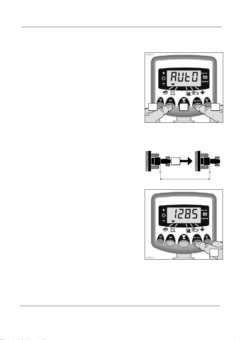
Figure 8: Stop Autocal
Figure 7: Start AutoCal
100 metres
6 5 3 4 2
4.4 ‘Autocal’ Speed Calibration
Auto-calibrate in field conditions for
maximum accuracy.
1. Place two markers 100 metres apart and position
some reference point on the tractor (e.g. the cab step)
opposite the first marker.
2. Select the forward speed channel.
3. Press and hold the CAL button until the cal
factor appears on the display. (7.8)
4. Continue holding the CAL button and press
the Ha>0 button.
The display will show "AUtO" ready to start the test run (fig. 7).
5. Drive up to the second marker and stop exactly
opposite the marker. The instrument counts and
displays the pulses received from the speed sensor
over the measured distance.
NOTE: The instrument only displays up to 9999.
Beyond this number of pulses it displays the
first 4 digits of a five-digit number, however the
pulses are still being counted internally.
Press the Ha>0 button (fig. 8).
The calibration factor is automatically calculated
and stored in memory.
The instrument then returns to the normal
display mode.
14
Page 15
HE-VA Auto-Controller AC-Lite - May 2016
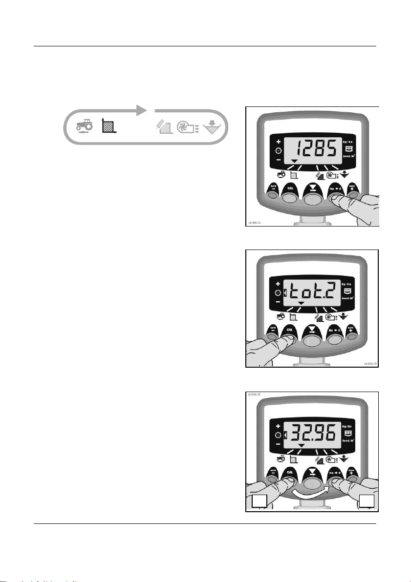
Figure 11: Zero Area Total
Figure 10: Select Area Register 1 / 2
Figure 9: Select Area Channel
1
2
5. Area Display
5.1 View Area Totals
The area display is derived from the forward
speed input and the programmed implement width.
There are two area registers. Each can be
independently reset to zero.
Press the CAL button to toggle between the two
area registers 'tot.1' and 'tot.2'.
The display then shows the area accumulated
since that total was last reset.
5.2 Zero Area Total
1. Select the total 1 or total 2 and release.
2. HOLD the Ha>0 button for 5 seconds.
The display flashes and the instrument sounds
5 beeps, before the total resets to zero.
15
Page 16
HE-VA Auto-Controller AC-Lite - May 2016
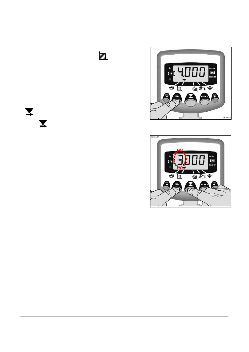
Figure 13 : Change Implement Width
Figure 12 : View Implement Width
5.3 Set Implement Width
1. Select the Area Total channel ( ).
2. Press and hold the CAL button for 5 seconds.
The display will flash "tot.1", then "tot.2" then
show the programmed implement width (fig. 12).
Default width = 4 metres.
3. Continue holding the CAL button and PRESS
to select the digit/decimal point to change.
4. HOLD to change the digit (or move the
decimal point). Releasing the button selects
the next digit (fig. 13).
5. Release the CAL button to return to the
normal display mode.
16
Page 17
HE-VA Auto-Controller AC-Lite - May 2016
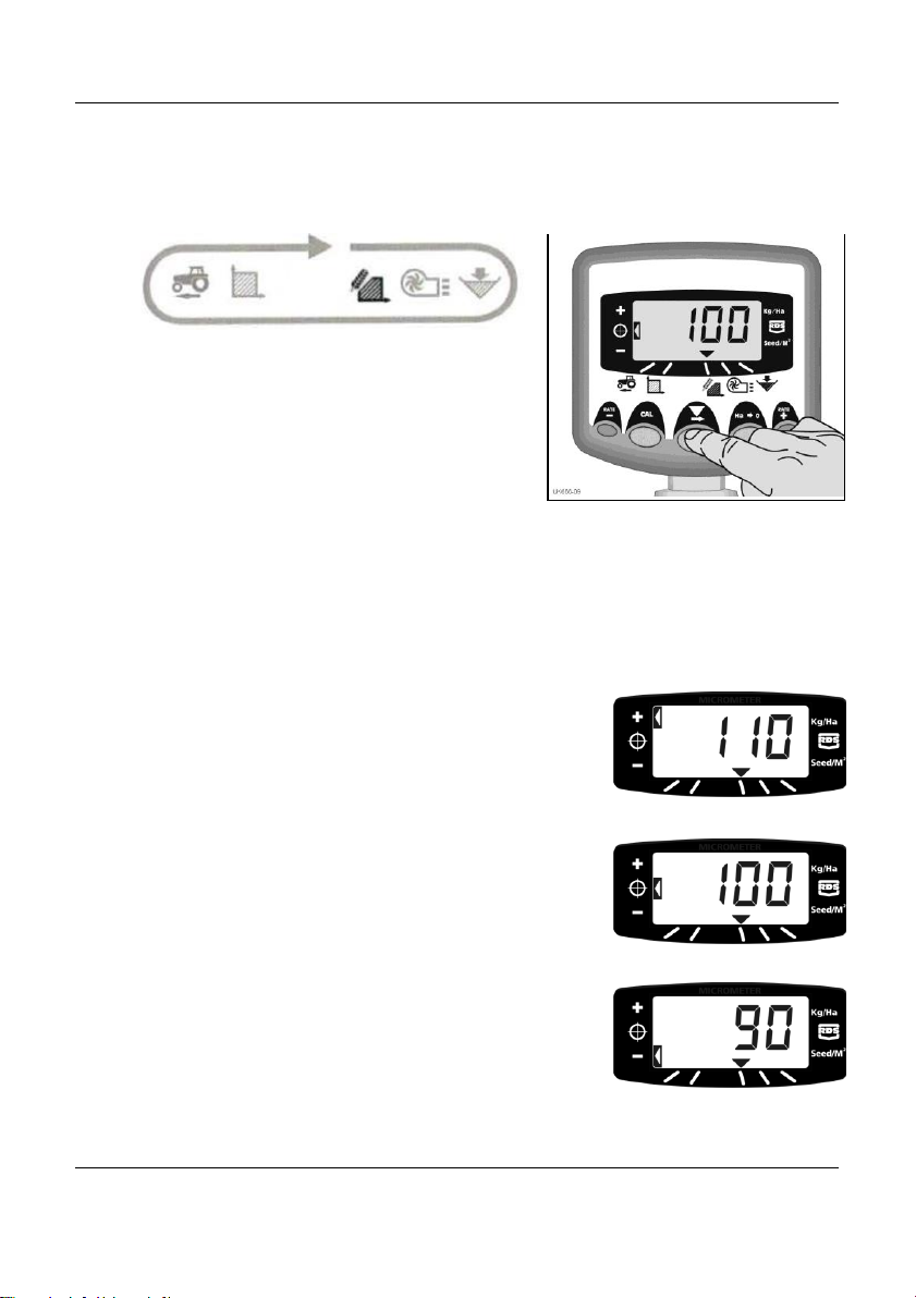
Figure 14: View Drilling Rate (kg/ha)
Pos. 1
Pos. 2
Pos. 3
6. Drilling Rate Functions
6.1 View Drilling Rate
This channel displays the current drilling rate
in Kg/Ha only.
The resolution for Kg/Ha units is:
0 to 24.9 0.1 Kg
25 to 250 1 Kg
250 to 9995 5 Kg
6.2 Adjusting the Drilling Rate
Press the RATE - button to decrease the
drilling rate.
Press the RATE + button to increase the
drilling rate.
The rate adjusts by the % step programmed
in programme mode 3, i.e. 5%, 10%, 15%,
20% or 25% of the programmed target or
base drilling rate.
6.3 Drilling Rate Indicator
The left indicator is used to remind the
operator of his drilling rate. When the
indicator is in position 2, then the Multi-Seeder
is operating at the target rate.
If the indicator is in position 1 then the actual
rate is increased from the target rate.
If the indicator is in position 3 then the actual
rate is decreased from the target rate.
17
Page 18
HE-VA Auto-Controller AC-Lite - May 2016
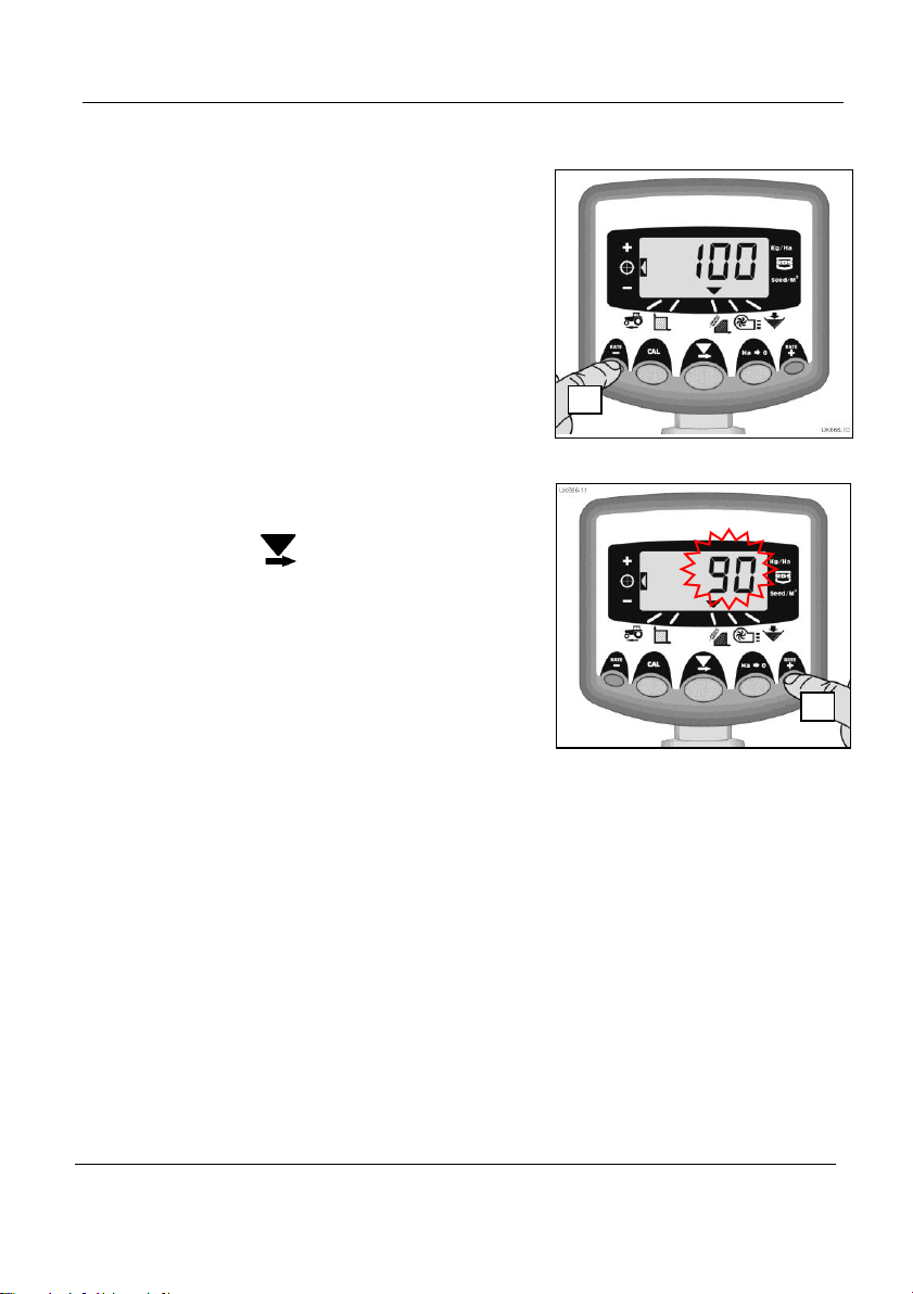
Figure 16: Adjust Target Rate
Figure 15: View current Target Rate
1
2
6.4 Changing the Target Rate
If the drilling rate is currently at the target
rate (the rate indicator at position 2), then:
1. With the rate display selected, press and
hold either the RATE + button or the
RATE - button for 5 seconds (fig. 15),
then release the button. The display will flash.
2. Press and hold either the RATE + button to
increase the target rate, or the RATE –
button to decrease the target rate (fig. 16).
The longer the switch is held, the faster
the number changes.
3. When the desired target rate is displayed,
press and hold the button.
The instrument will beep 5 times and the display
will alternate between the set rate and the calculated
minimum forward speed for that rate. After 5 seconds,
the instrument will display ‘donE’ after which the
button can be released to return to normal
operating mode.
18
Page 19

HE-VA Auto-Controller AC-Lite - May 2016
6.5 Product Calibration
Ensure the feed roll setup is appropriate for the intended seed type, application
rate and forward speed range for application. Please refer to the relevant
sections of the HE-VA ApS Fitting and Operating Instructions if necessary.
1. Place a container under the seed outlet of the metering
unit then press and hold the PRIME button to dispense
the product.
2. The instrument automatically switches to the programme mode, and the display will
count up the theoretical weight (in grams) of product based on the calibration factor
currently stored in memory.
3. Once you have dispensed sufficient product, release the priming switch and weigh
the product metered out. The theoretical weight will remain flashing on the display.
NOTE: If the priming switch is held for long enough to exceed 9999 grams then the
instrument will simply show ‘HiGh’, informing the operator that he must re-test to
ensure the weight does not exceed 9999 grams. Simply release the PRIME button
and press again when ready to restart the count from zero.
4. Adjust the displayed weight to match the measured weight using the RATE + or
RATE - buttons.
5. Press the Ha>0 button once to display the calculated minimum forward speed
(see note).
6. Press the Ha>0 button again to save the new calibration factor. The instrument
displays ‘donE’ to indicate the new factor is now stored. After 3 seconds, the
instrument reverts back to the normal operating mode.
NOTE : The instrument makes the calculation from the entered working width, target
application rate, and the metered weight delivered whilst calibrating. If you find that
you cannot achieve your desired field speed, then re-configure the feed roll assembly
and repeat the calibration procedure.
19
Page 20
HE-VA Auto-Controller AC-Lite - May 2016
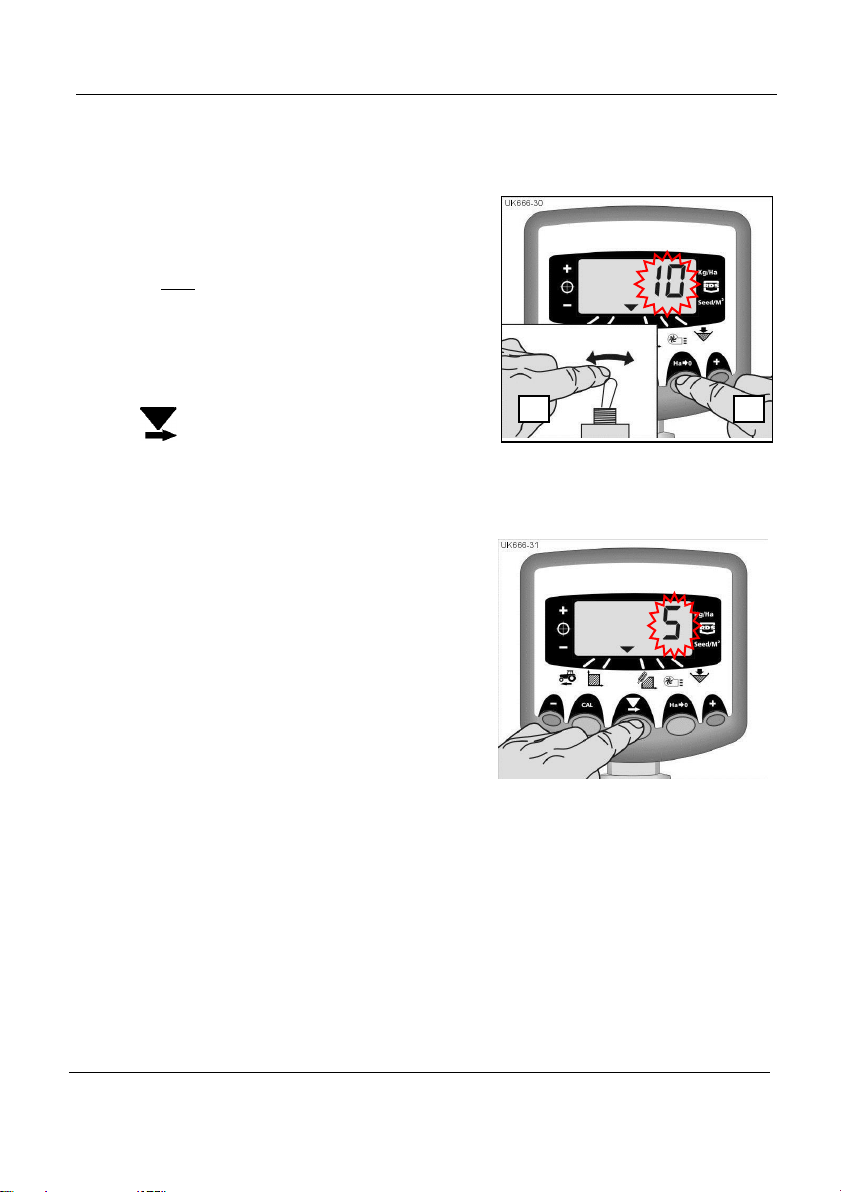
Figure 17: Set % Rate Step
2
3
Figure 18: Change % Rate Step
6.6 Set % Step for Rate Offset
This sets the amount by which the rate is
adjusted away from the target rate when you
press the RATE + or RATE - buttons.
1. Press and hold the Ha>0 button as you switch
the instrument on. The instrument is then in
programme mode 3 on channel 1.
2. The display will show a number indicating
the % step (5 - 25% in 5% increments) (fig. 18).
3. PRESS to select the required % step.
4. Switch off and on again to resume normal
operating mode.
20
Page 21
HE-VA Auto-Controller AC-Lite - May 2016
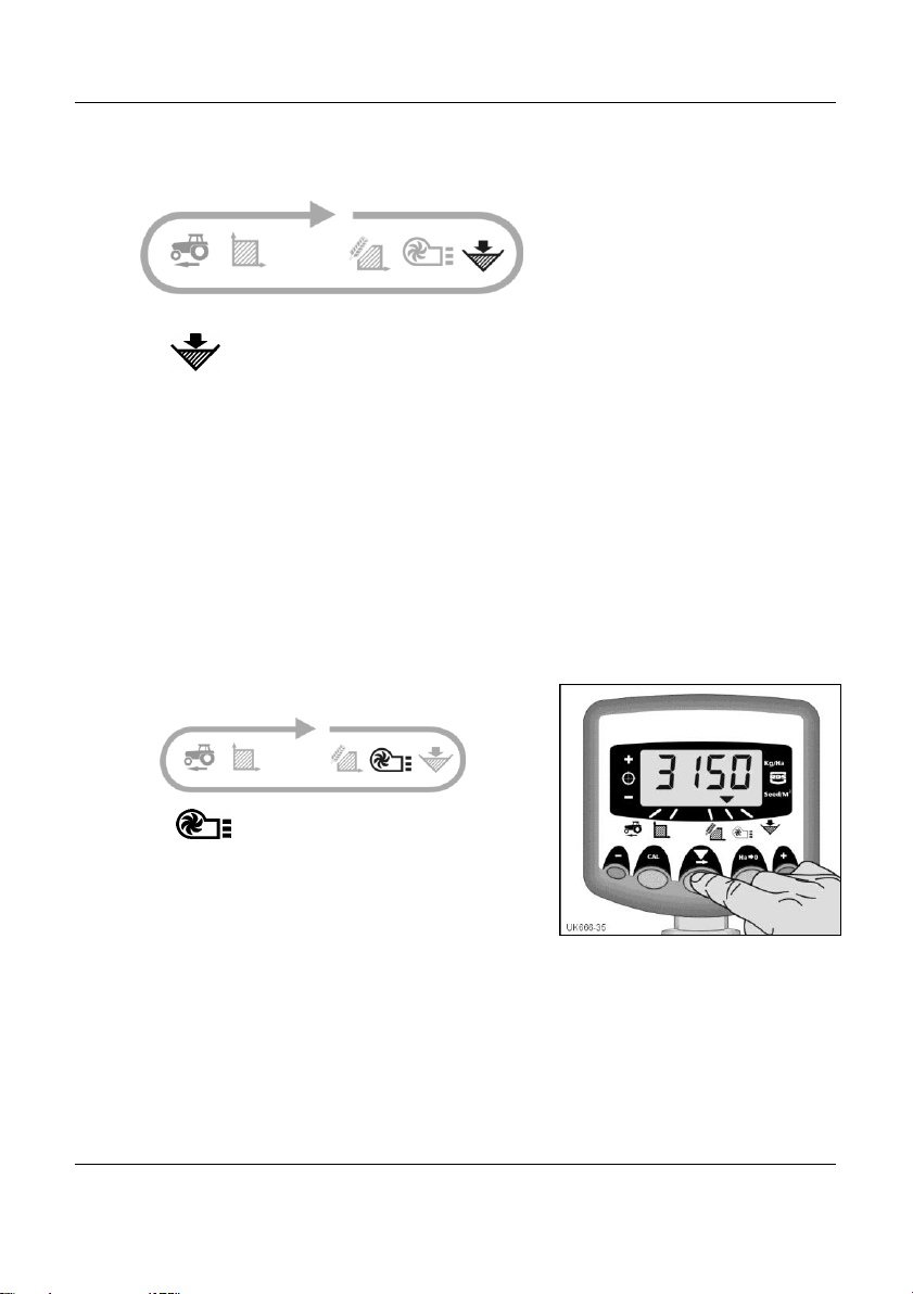
Figure 19: Display Fan Speed
7. Hopper level Alarm
When the hopper level sensor is uncovered, the instrument defaults to the hopper level
channel ( ), beeps 5 times and flashes ‘ALAr’ every 30 seconds.
The alarm can be cancelled temporarily by selecting another channel, but will revert to
the hopper level display and repeat the alarm after 30 seconds until the hopper is
refilled.
7.1 Feed roll monitoring
If the feed roll stops during operation (e.g. the chain between the motor and the feed
roll is breaking), the hopper level alarm will be activated too.
8. Fan Speed / Speed Alarms
Display Fan Speed
Select the channel.
Fan Speed displays for 10 seconds before
returning to the tramline display.
Fan Speed Alarms
There is a programmable high speed alarm and a programmable
low speed alarm. An alarm condition causes the instrument to default to the fan speed
channel, sound 5 beeps and flash the actual fan speed.
Cancel the alarm by restoring the fan speed within the programmed limits.
NOTE: The alarm is inhibited if the forward speed is less than 2 km/h.
Defaults Alarm Thresholds:
Low speed = 2700 rpm, High speed = 4500 rpm
21
Page 22
HE-VA Auto-Controller AC-Lite - May 2016
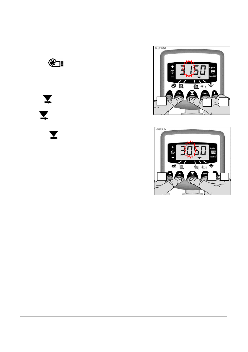
Figure 20: Low speed alarm
threshold
3
2
Figure 21: Set low speed alarm
threshold
4
2
5
1
Set Low Fan Speed Alarm
1. Select the channel.
2. Hold CAL to enter programme mode 1.
The alarm threshold is displayed after 3 seconds.
Continue holding the button and…
3. PRESS to select the digit or decimal point to
change.
4. HOLD to change the selected digit
(or move the decimal point).
5. RELEASE to select the next digit and
repeat as above, otherwise simply release
both buttons. The instrument will then return
to the normal display mode.
22
Page 23

HE-VA Auto-Controller AC-Lite - May 2016
Mode 1
Mode 2
Mode 3
(Product
calibration)
Mode 4
Mode 5
Mode
Entry
From normal
display mode,
select channel
and hold CAL
button
continuously
Press and hold
CAL button for
10 seconds
while switching
instrument on
Press and hold
HA-0 button while
switching
instrument on
Press and
hold RATE+
button for 10
seconds while
switching
instrument on
Press and
hold RATE-
button for 10
seconds while
switching
instrument on
Channel
selection
-
Press CAL
button
Press HA-0
button
Press RATE+
button
Press RATE-
button
Channel 1
Speed Sensor
Factor
[7.78 mm/pulse]
(see section 4.3)
Simulated
Speed
[10 km/h]
Rate selection
(kg/ha)
Pulses /
metering unit
rev. [600]
Cut Out Alarm
Speed
[2.00 km/h]
Channel 2
Implement Width
[4.0 m]
(see section 5.3)
Grand Total
Area [ha]
Thousand Grain
Weight [45]
Response
[1000]
Shaft Conf
[Hop]
Channel 3
-------
-------
Rate - % Step
[5%]
(see section 6.6)
-------
Channel 4
Seed calibration
factor
[0.01 kg/rev)
Automatic
pre-start
[OFF]
Expected Weight
(0-9999 grams)
(see section 6.5)
Motor
Calibration
Speed
[35 rpm]
Channel 5
Low Fan Speed
Alarm
[2500rpm]
[4500]
*see note 1
Minimum Fwd
speed
(see section 6.5)
Fan PPR
[0.000]
*see note 1
Channel 6
Hopper Level
Alarm
On / Off
[On]
Pre-start time
[4 seconds]
Calibration
complete
(see section 6.5)
Minimum
Metering
Speed
[3 rpm]
9. Programme Functions and Fault Diagnosis
9.1 Programme (CAL) Modes 1 – 5
Some settings do not need to be accessed during normal operation, unless the system
is transferred to another implement. Those settings that need to be accessed during
normal operation are explained in the operators’ section (sections 3 - 7) of the manual.
*Note 1: Used to set the number of pulses the fan sensor sees for 1 revolution
23
Page 24

HE-VA Auto-Controller AC-Lite - May 2016
Condition
Possible reasons
When in work and moving, the Instrument
displays ‘C.out’ and beeps every 5
seconds
The forward speed is above 2km/h while
the Multi-Seeder is out of work.
The cutout switch is not operating correctly
when the implement is lifted or lowered.
When in work the instrument flashes
‘ALAr’ and beeps.
Hopper level is low.
When in work the instrument defaults to
the rate channel, displays ‘FaiL’ and beeps
every 30 seconds. The metering roll does
not turn.
The metering motor has stopped due to an
internal fault with the motor or the encoder,
or the external power supply.
First switch the instrument off and back on
to try and clear the fault. Otherwise, check
the wiring connections (both power supply
and encoder) and try again.
When in work the instrument defaults to
the rate channel, displays ‘StAL’ and
beeps every 30 seconds. The metering
roll does not turn.
The metering motor has stalled. It has
automatically stopped to prevent further
damage.
Investigate the metering mechanism.
When in work the instrument defaults to
the application rate channel, flashes a rate
lower than the target and beeps
continuously.
The application rate is low because the
forward speed is too high and the target
motor speed cannot be achieved.
Reduce your speed or change the metering
roll and recalibrate.
When in work the instrument defaults to
the forward speed channel, the speed
display flashes and beeps continuously.
Forward speed is too low. The metering roll
is at its minimum possible rpm.
Increase your speed, or if this would be too
fast, change the metering roll and
recalibrate.
If you find that the minimum forward speed
is too high at low application rates you
should change the feed roll to a lower
volume roll and redo the product
calibration.
9.2 Fault Diagnosis
24
Page 25

HE-VA Auto-Controller AC-Lite - May 2016
Multi-Seeder Make/Model
Instrument Serial No.
Speed Sensor Factor [mm/pulse]
Implement Width [m]
Units [kg/ha]
Seed Type
Application
Rate
No. of rolls
Seed Cal.
Factor
[kg/rev]
10. Calibration Record
25
Page 26

HE-VA Auto-Controller AC-Lite - May 2016
26
Page 27

HE-VA Auto-Controller AC-Lite - May 2016
27
Page 28

HE-VA Auto-Controller AC-Lite - May 2016
28
 Loading...