

Page 1
11.07 Andreas Hettich GmbH & Co. KG AB5600DEENFRIT
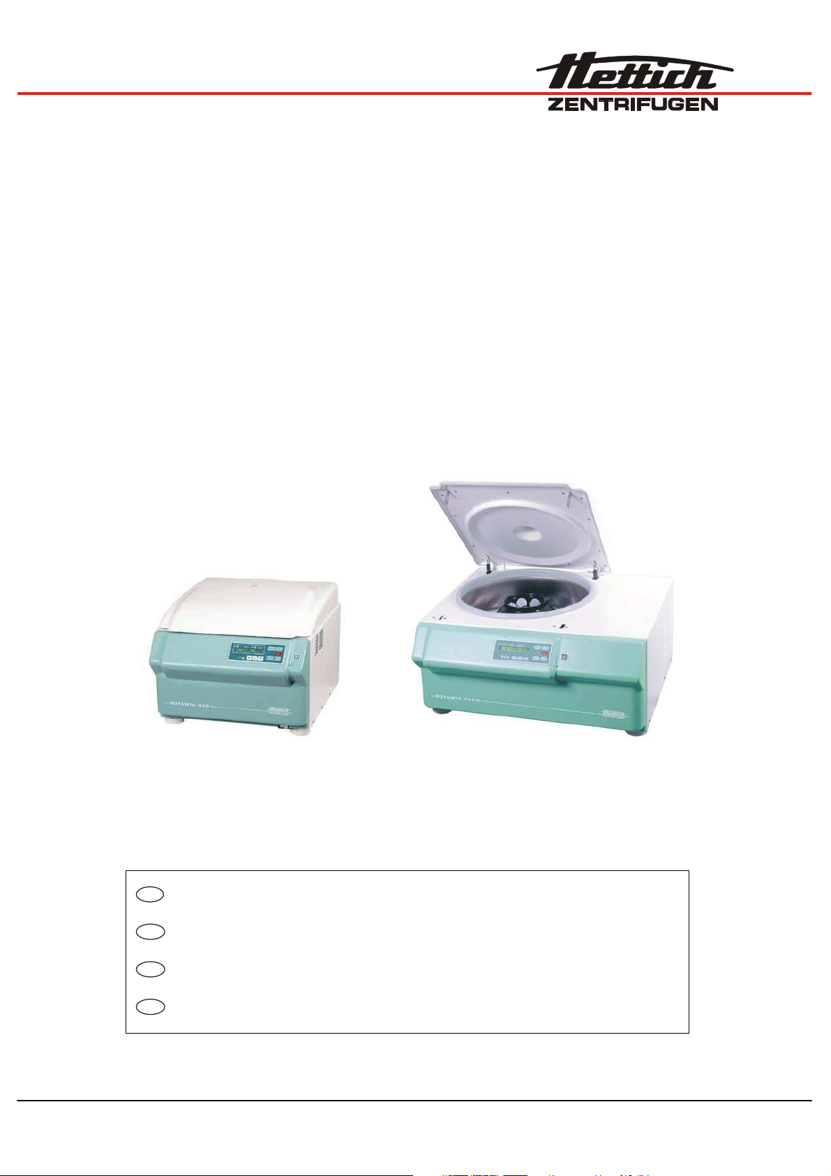
ROTANTA 460
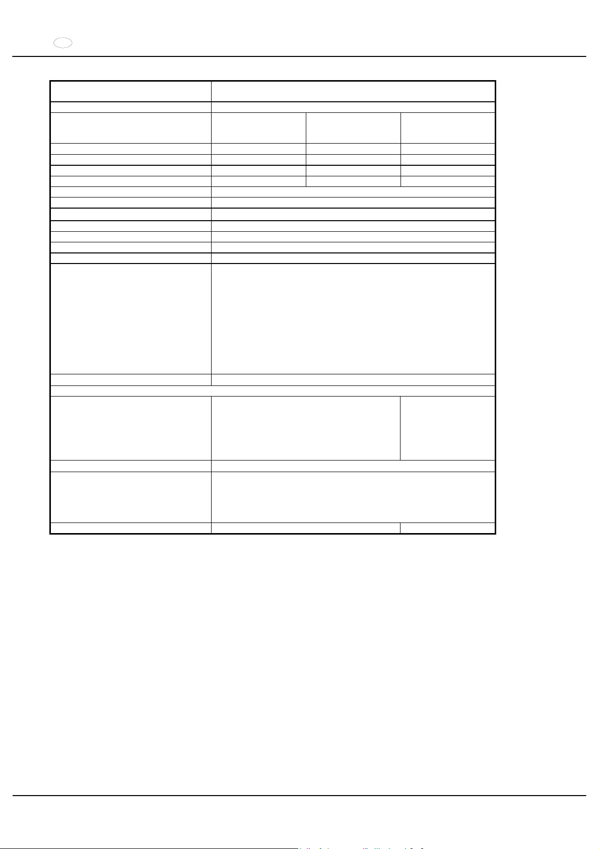
ROTANTA 460 R
DE
Bedienungsanleitung...................................................... 5
EN
Operating Instructions.................................................... 22
FR
Mode d'emploi ................................................................. 37
IT
Istruzioni per l'uso .......................................................... 53
Page 2
2/104
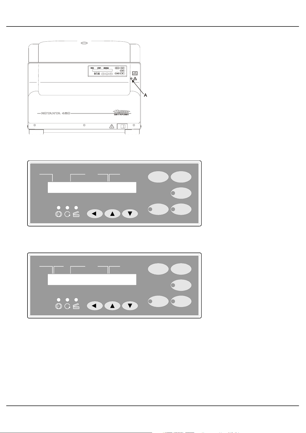
Fig. 1
IMPULS START
STOP
RCFPROG
PROG >RCF< RPM t/min
1
4000
22:11
Fig. 2 ROTANTA 460
IMPULS START
STOP
RCFPROG
PROG >RCF< RPM t/minT/°C
1
400020
22:11
Fig. 3 ROTANTA 460 R
Page 3
3/104
EG-Konformitätserklärung
EC Conformity Declaration
Déclaration de conformité CE
Dichiarazione di conformità alle norme CEE
Andreas Hettich GmbH & Co. KG x Föhrenstraße 12 x D-78532 Tuttlingen x Germany
Das bezeichnete Gerät, inklusive Zubehör entspricht den aufgeführten EG-Richtlinien und Normen.
The denoted device, including accessories corresponds to the listed EC guidelines and standards.
L'appareil désigné, y compris les accessoires, correspond aux directives CE et aux normes énumérées.
L'apparecchio designato, compresi gli accessori, è conforme alle direttive CE e alle norme citate.
Geräteart, Type of device, Type d'appareil, Tipo di apparecchio:
Laborzentrifuge mit Zubehör, Laboratory centrifuge with accessories, Centrifugeuse de
laboratoire avec des accessoires, Centrifuga da laboratorio con accessori
Typenbezeichnung, Type designation, Désignation de modèle, Contrassegno tipo:
ROTANTA 460 / ROTANTA 460 R
EG-Richtlinien/Normen, EC guidelines/standards, Directives CE/Normes, Direttive/Norme CEE:
73/23/EWG, EN 61010-1, EN 61010-2-020
89/336/EWG + 92/31/EWG + 93/68/EWG, EN 61000-6-1, EN 55011, EN 61000-3-2, EN 61000-3-3
98/37/EG, EN ISO 12100-1, EN ISO 12100-2
98/79/EG
Tuttlingen, 29.10.2007
H. Eberle
Page 4

4/104
Andreas Hettich GmbH & Co. KG
Föhrenstraße 12, D-78532 Tuttlingen / Germany
Phone +49 (0)7461 / 705-0
Fax +49 (0)7461 / 705-125
[email protected], [email protected]
www.hettichlab.com
© 2002 by Andreas Hettich GmbH & Co. KG
All rights reserved. No part of this publication may be reproduced without the written prior permission of the copyright
owner.
Änderungen vorbehalten! , Modifications reserved! , Sous réserve de modifications ! , Con riserva di modifiche!
AB5600DEENFRIT / 11.07
Page 5

DE
5/104
Inhaltsverzeichnis
1 Bestimmungsgemäße Verwendung........................................................................................................................7
2 Restrisiken..............................................................................................................................................................7
3 Technische Daten...................................................................................................................................................7
4 Sicherheitshinweise ................................................................................................................................................9
5 Bedeutung der Symbole .......................................................................................................................................10
6 Lieferumfang.........................................................................................................................................................10
7 Auspacken der Zentrifuge.....................................................................................................................................10
8 Inbetriebnahme.....................................................................................................................................................11
9 Deckel öffnen und schließen.................................................................................................................................11
9.1 Deckel öffnen.................................................................................................................................................11
9.2 Deckel schließen ...........................................................................................................................................11
10 Ein- und Ausbau des Rotors..............................................................................................................................12
11 Beladen des Rotors...........................................................................................................................................12
12 Winkelrotoren aerosoldicht verschließen...........................................................................................................12
13 Bedien- und Anzeigeelemente ..........................................................................................................................13
13.1 Symbole des Bedienfeldes.........................................................................................................................13
13.2 Tasten des Bedienfeldes............................................................................................................................13
13.3 Einstellmöglichkeiten..................................................................................................................................13
14 Zentrifugations–Parameter eingeben ................................................................................................................14
15 Programmierung................................................................................................................................................14
15.1 Programm-Eingabe / -Änderung ................................................................................................................14
15.2 Programm-Abruf.........................................................................................................................................14
16 Zentrifugation ....................................................................................................................................................15
16.1 Zentrifugation mit Zeitvorwahl ....................................................................................................................15
16.2 Dauerlauf ...................................................................................................................................................15
16.3 Kurzzeitzentrifugation.................................................................................................................................15
17 Not-Stop ............................................................................................................................................................15
18 Akustisches Signal ............................................................................................................................................16
19 Betriebsstunden-Abfrage...................................................................................................................................16
20 Kühlung (nur bei Zentrifuge mit Kühlung)..........................................................................................................16
20.1 Standby-Kühlung .......................................................................................................................................16
20.2 Vorkühlen des Rotors.................................................................................................................................16
21 Heizung (nur bei Zentrifuge mit Option Heizen/Kühlen) ....................................................................................16
22 Relative Zentrifugalbeschleunigung (RCF)........................................................................................................17
23 Zentrifugation von Stoffen mit höherer Dichte ...................................................................................................17
24 Rotor-Erkennung ...............................................................................................................................................17
25 Notentriegelung.................................................................................................................................................17
26 Pflege und Wartung...........................................................................................................................................18
26.1 Zentrifuge...................................................................................................................................................18
26.2 Rotoren und Zubehör.................................................................................................................................18
26.2.1 Tragzapfen..........................................................................................................................................18
26.2.2 Rotoren und Zubehör mit begrenzter Verwendungsdauer ..................................................................18
26.3 Autoklavieren .............................................................................................................................................19
Page 6

DE
6/104
26.4 Zentrifugiergefäße......................................................................................................................................19
27 Störungen.......................................................................................................................................................... 20
28 Reparaturannahme von Zentrifugen ................................................................................................................. 21
29 Entsorgung........................................................................................................................................................ 21
30
Anhang / Appendix............................................................................................................................................ 69
30.1 Rotoren und Zubehör / Rotors and accessories.........................................................................................69
Page 7
DE
7/104
1 Bestimmungsgemäße Verwendung
Bei der vorliegenden Maschine handelt es sich um ein Medizinprodukt (Laborzentrifuge) im Sinne der IVD-Richtline
98/79/EG. Die Zentrifuge dient zum Trennen von Stoffen bzw. Stoffgemischen mit einer Dichte von max. 1,2 kg/dm³.
Darunter fallen auch Stoffe und Stoffgemische menschlichen Ursprungs. Die Zentrifuge ist nur für diesen
Verwendungszweck bestimmt. Eine andere oder darüber hinausgehende Benutzung gilt als nicht
bestimmungsgemäß. Für hieraus entstehende Schäden haftet die Firma Andreas Hettich GmbH & Co. KG nicht.
Zur bestimmungsgemäßen Verwendung gehört auch das Beachten aller Hinweise aus der Bedienungsanleitung und
die Einhaltung der Inspektions- und Wartungsarbeiten.
2 Restrisiken
Die Maschine ist nach dem Stand der Technik und den anerkannten sicherheitstechnischen Regeln gebaut. Bei
unsachgemäßer Verwendung und Behandlung können Gefahren für Leib und Leben des Benutzers oder Dritter bzw.
Beeinträchtigungen an der Maschine oder an anderen Sachwerten entstehen. Die Maschine ist nur für die
bestimmungsgemäße Verwendung, und nur in sicherheitstechnisch einwandfreiem Zustand zu benutzen.
Störungen, die die Sicherheit beeinträchtigen können, sind umgehend zu beseitigen.
3 Technische Daten
Hersteller
Andreas Hettich GmbH & Co. KG
D-78532 Tuttlingen
Modell ROTANTA 460
Typ 5600 5600-01
Netzspannung (r 10%) 208-240 V 1a
110-127 V 1~
Netzfrequenz 50 - 60 Hz 50 - 60 Hz
Anschlusswert 1500 VA 1300 VA
Stromaufnahme 6.5 A 11 A
Kältemittel ---Kapazität max. 4 x 750 ml
zulässige Dichte
1.2 kg/dm
3
Drehzahl (RPM) 15000
Beschleunigung (RCF) 24400
Kinetische Energie 41000 Nm
Prüfpflicht (BGR 261) ja
Umgebungsbedingungen (EN 61010-1)
Aufstellungsort
nur in Innenräumen
Höhe
bis zu 2000 m über Normal-Null
Umgebungstemperatur
2°C bis 40°C
Luftfeuchtigkeit
maximale relative Luftfeuchte 80% für Temperaturen bis 31°C, linear
abnehmend bis 50% relativer Luftfeuchte bei 40°C.
Überspannungskategorie
(IEC 60364-4-443)
,,
Verschmutzungsgrad
2
Geräteschutzklasse
,
nicht für den Einsatz in explosionsgefährdeter Umgebung geeignet.
EMV
Störaussendung (Funkentstörung)
EN 55011,
Gruppe 1, Klasse B
EN 61000-3-3
FCC Class A
Störfestigkeit
EN 61000-6-1 ----
Geräuschpegel (rotorabhängig)
d 67 dB(A)
Abmessungen
Breite
554 mm
Tiefe
707 mm
Höhe
453 mm
Gewicht 106 kg 115 kg
Page 8
DE
8/104
Hersteller
Andreas Hettich GmbH & Co. KG
D-78532 Tuttlingen
Modell ROTANTA 460 R
Typ
5605,
5605-20
5605-50
5605-07
5605-01,
5605-51
Netzspannung (r 10%) 208-240 V 1a
208-240 V 1~ 110-127 V 1~
Netzfrequenz 50 - 60 Hz 60 Hz 60 Hz
Anschlusswert 2400 VA 2200 VA 2000 VA
Stromaufnahme 10 A 10 A 16 A
Kältemittel R 404A
Kapazität max. 4 x 750 ml
zulässige Dichte
1.2 kg/dm
3
Drehzahl (RPM) 15000
Beschleunigung (RCF) 24400
Kinetische Energie 51000 Nm
Prüfpflicht (BGR 261) ja
Umgebungsbedingungen (EN 61010-1)
Aufstellungsort
nur in Innenräumen
Höhe
bis zu 2000 m über Normal-Null
Umgebungstemperatur
5°C bis 35°C
Luftfeuchtigkeit
maximale relative Luftfeuchte 80% für Temperaturen bis 31°C, linear
abnehmend bis 50% relativer Luftfeuchte bei 40°C.
Überspannungskategorie
(IEC 60364-4-443)
,,
Verschmutzungsgrad
2
Geräteschutzklasse
,
nicht für den Einsatz in explosionsgefährdeter Umgebung geeignet.
EMV
Störaussendung (Funkentstörung)
EN 55011,
Gruppe 1, Klasse B
EN 61000-3-3
FCC Class A
Störfestigkeit
EN 61000-6-1 ----
Geräuschpegel (rotorabhängig)
d 64 dB(A)
Abmessungen
Breite
770 mm
xTiefe
707 mm
xHöhe
453 mm
Gewicht 147 kg 156 kg
Page 9

DE
9/104
4 Sicherheitshinweise
Bei Nichteinhaltung dieser Hinweise kann beim Hersteller kein Gewährleistungsanspruch geltend
gemacht werden.
xVor Inbetriebnahme der Zentrifuge ist die Bedienungsanleitung zu lesen und zu beachten.
Nur Personen, die die Bedienungsanleitung gelesen und verstanden haben, dürfen das Gerät bedienen.
xNeben der Bedienungsanleitung und den verbindlichen Regelungen der Unfallverhütung sind auch die
anerkannten fachtechnischen Regeln für sicherheits- und fachgerechtes Arbeiten zu beachten. Die
Bedienungsanleitung ist um Anweisungen aufgrund bestehender nationaler Vorschriften des Verwenderlandes
zur Unfallverhütung und zum Umweltschutz zu ergänzen.
xDie Zentrifuge ist nach dem Stand der Technik gebaut und betriebssicher.
Es können aber von ihr Gefahren für den Benutzer oder Dritte ausgehen, wenn sie nicht von geschultem
Personal oder unsachgemäß oder zu nicht bestimmungsgemäßem Gebrauch eingesetzt wird.
xDie Zentrifuge ist so aufzustellen, dass sie standsicher betrieben werden kann.
xVor Benutzung der Zentrifuge unbedingt den Rotor auf festen Sitz prüfen.
xWährend eines Zentrifugationslaufes dürfen sich gemäß IEC 61010-2-020, in einem Sicherheitsbereich von
300 mm um die Zentrifuge herum, keine Personen, Gefahrstoffe und Gegenstände befinden.
xDie Zentrifuge darf während des Betriebs nicht bewegt oder angestoßen werden.
xIm Störungsfall bzw. bei der Notentriegelung nie in den sich drehenden Rotor greifen.
xUm Schäden durch Kondensat zu vermeiden, muss bei Wechsel von einem kalten in einen warmen Raum die
Zentrifuge entweder mindestens 3 Stunden im warmen Raum aufwärmen bevor sie an das Netz angeschlossen
werden darf oder 30 Minuten im kalten Raum warmlaufen.
xEs dürfen nur die vom Hersteller für dieses Gerät zugelassenen Rotoren und das zugelassene Zubehör
verwendet werden (siehe Kapitel "Anhang/Appendix, Rotoren und Zubehör/Rotors and accessories").
xDer Rotor der Zentrifuge darf nur entsprechend dem Kapitel "Beladen des Rotors" beladen werden.
xBei der Zentrifugation mit maximaler Drehzahl darf die Dichte der Stoffe oder Stoffgemische 1,2 kg/dm
3
nicht
überschreiten.
xZentrifugationen mit unzulässiger Unwucht sind nicht erlaubt.
xDie Zentrifuge darf nicht in explosionsgefährdeter Umgebung betrieben werden.
xEine Zentrifugation mit:
brennbaren oder explosiven Materialien
Materialien, die chemisch mit hoher Energie miteinander reagieren ist verboten.
xBei der Zentrifugation von gefährlichen Stoffen bzw. Stoffgemischen, die toxisch, radioaktiv oder mit pathogenen
Mikroorganismen verseucht sind, sind durch den Benutzer geeignete Maßnahmen zu treffen.
Es müssen grundsätzlich Zentrifugiergefäße mit speziellen Schraubverschlüssen für gefährliche Substanzen
verwendet werden. Bei Materialien der Risikogruppe 3 und 4 ist zusätzlich zu den verschließbaren
Zentrifugiergefäßen ein Bio-Sicherheitssystem zu verwenden (siehe Handbuch "Laboratory Biosafety Manual"
der Weltgesundheitsorganisation).
Bei einem Bio-Sicherheitssystem verhindert eine Bioabdichtung (Dichtring) zwischen Gehänge und Deckel das
Austreten von Tröpfchen und Aerosolen.
Wird das Gehänge eines Bio-Sicherheitssystems ohne den Deckel verwendet, muss der Dichtring vom Gehänge
entfernt werden, um eine Beschädigung des Dichtrings während des Zentrifugationslaufes zu vermeiden.
Beschädigte Dichtringe dürfen nicht mehr zum Abdichten des Bio-Sicherheitssystems verwendet werden.
Ohne Verwendung eines Bio-Sicherheitssystems ist eine Zentrifuge im Sinne der Norm EN 61010-2-020 nicht
mikrobiologisch dicht.
Lieferbare Bio-Sicherheitssysteme siehe Kapitel "Anhang/Appendix, Rotoren und Zubehör/Rotors and
accessories". Im Zweifelsfall sind entsprechende Informationen beim Hersteller einzuholen.
xDer Betrieb der Zentrifuge mit stark korrodierenden Stoffen, welche die mechanische Festigkeit von Rotoren,
Gehängen und Zubehörteilen beeinträchtigen können, ist nicht erlaubt.
xRotoren, Gehänge und Zubehörteile, die starke Korrosionsspuren oder mechanische Schäden aufweisen, oder
deren Verwendungsdauer abgelaufen ist, dürfen nicht mehr verwendet werden.
xReparaturen dürfen nur von einer vom Hersteller autorisierten Person ausgeführt werden.
xEs dürfen nur Originalersatzteile und zugelassenes Originalzubehör der Firma Andreas Hettich GmbH & Co. KG
verwendet werden.
xEs gelten die folgenden Sicherheitsbestimmungen:
IEC 61010-1 und IEC 61010-2-020 sowie deren nationalen Abweichungen.
xDie Sicherheit und Zuverlässigkeit der Zentrifuge ist nur dann gewährleistet, wenn:
die Zentrifuge nach der Bedienungsanleitung betrieben wird.
die elektrische Installation, am Aufstellungsort der Zentrifuge, den Anforderungen von IEC Festlegungen
entspricht.
vorgeschriebene Prüfungen nach BGV A1, BGR 261 durch einen Sachkundigen durchgeführt werden.
Page 10
DE
10/104
5 Bedeutung der Symbole
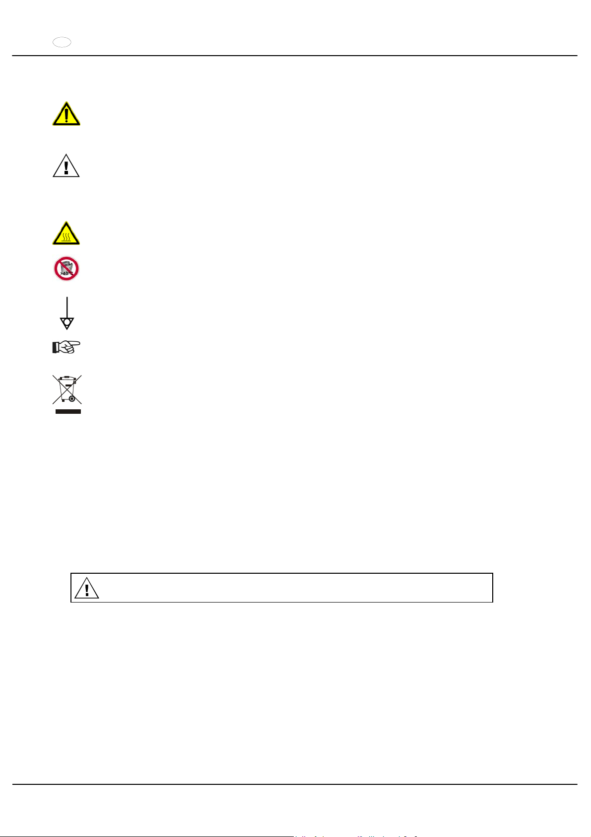
Symbol an der Maschine:
Achtung, allgemeine Gefahrenstelle.
Vor Benutzung der Zentrifuge unbedingt die Bedienungsanleitung lesen und die sicherheitsrelevanten
Hinweise beachten!
Symbol in der Bedienungsanleitung:
Achtung, allgemeine Gefahrenstelle.
Dieses Symbol kennzeichnet sicherheitsrelevante Hinweise und deutet auf mögliche gefährliche
Situationen hin.
Das Nichtbeachten dieser Hinweise kann zu Sach- und Personenschäden führen.
Symbol an der Maschine und in der Bedienungsanleitung:
Warnung vor heißer Oberfläche.
Symbol an der Maschine und in der Bedienungsanleitung:
Das Kunststoff-Nutgehänge Best.-Nr. 5091 darf nur bei Temperaturen bis maximal 40°C verwendet
werden.
Symbol an der Maschine:
Äquipotential: Steckverbinder (PA-Stecker) für Potentialausgleich (nur bei Zentrifuge mit PA-Stecker).
Symbol in der Bedienungsanleitung:
Dieses Symbol deutet auf wichtige Sachverhalte hin.
Symbol an der Maschine und in der Bedienungsanleitung:
Symbol für die getrennte Sammlung von Elektro- und Elektronikgeräten, gemäß der Richtlinie
2002/96/EG (WEEE). Das Gerät gehört zur Gruppe 8 (Medizinische Geräte).
Verwendung in den Ländern der Europäischen Union sowie in Norwegen und der Schweiz.
6 Lieferumfang
1 Anschlusskabel
1 Sechskant-Stiftschlüssel 2,5 mm
1 Sechskant-Stiftschlüssel 5 mm
1 Schmierfett für Tragzapfen
1 Bedienungsanleitung
1 Hinweisblatt Transportsicherung
Rotor(en) und das entsprechende Zubehör werden je nach Bestellung mitgeliefert.
7 Auspacken der Zentrifuge
xDen Karton nach oben abheben und die Polsterung entfernen.
x
Nicht an der Frontblende anheben.
Das Gewicht der Zentrifuge beachten, siehe Kapitel "Technische Daten".
Die Zentrifuge, mit der angemessenen Anzahl von Helfern, an beiden Seiten anheben und auf den Labortisch
stellen.
Page 11
DE
11/104
8 Inbetriebnahme
xGemäß der Laborgerätenorm IEC 61010-2-020 muss in der Gebäudeinstallation ein Notausschalter zur
Trennung der Netzversorgung im Fehlerfall angebracht sein.
Dieser Schalter muss abseits der Zentrifuge angebracht sein, vorzugsweise außerhalb des Raumes, in dem sich
die Zentrifuge befindet, oder neben dem Ausgang dieses Raumes.
xDie Zentrifuge an einem geeigneten Platz standsicher aufstellen und nivellieren. Bei der Aufstellung ist der
geforderte Sicherheitsbereich gemäß IEC 61010-2-020, von 300 mm um die Zentrifuge herum, einzuhalten.
Während eines Zentrifugationslaufes dürfen sich gemäß IEC 61010-2-020, in einem Sicherheitsbereich von 300 mm um die Zentrifuge herum, keine Personen, Gefahrstoffe und Gegenstände
befinden.
xLüftungsöffnungen dürfen nicht zugestellt werden.
Es muss ein Lüftungsabstand von 300 mm um die Lüftungsschlitze oder Lüftungsöffnungen eingehalten werden.
xBei der Zentrifuge, Best.-Nr. 5605-20, die Stickstoffversorgung gemäß dem beigefügten Hinweisblatt
AH5605-20XX anschließen.
Das Anschließen der Zentrifuge muss unbedingt gemäß dem beigefügten Hinweisblatt erfolgen.
Das beigefügte Hinweisblatt unbedingt beachten.
xZentrifuge mit PA-Stecker:
Bei Bedarf den PA-Stecker an der Rückseite des Gerätes mit einem zusätzlichen medizinischen PotentialAusgleich-System verbinden.
xPrüfen ob die Netzspannung mit der Angabe auf dem Typenschild übereinstimmt.
xDie Zentrifuge mit dem Anschlusskabel an eine genormte Netzsteckdose anschließen. Anschlusswert siehe
Kapitel "Technische Daten".
xDen Netzschalter einschalten. Schalterstellung ",
".
Der Maschinentyp und die Programmversion werden angezeigt, die LED's leuchten. Nach 8 Sekunden wird
OPEN OEFFNEN angezeigt. Die LED leuchtet
xDen Deckel öffnen.
Die zuletzt benutzten Zentrifugierdaten werden angezeigt.
xDie Transportsicherung entfernen, siehe Hinweisblatt "Transportsicherung".
9 Deckel öffnen und schließen
9.1 Deckel öffnen
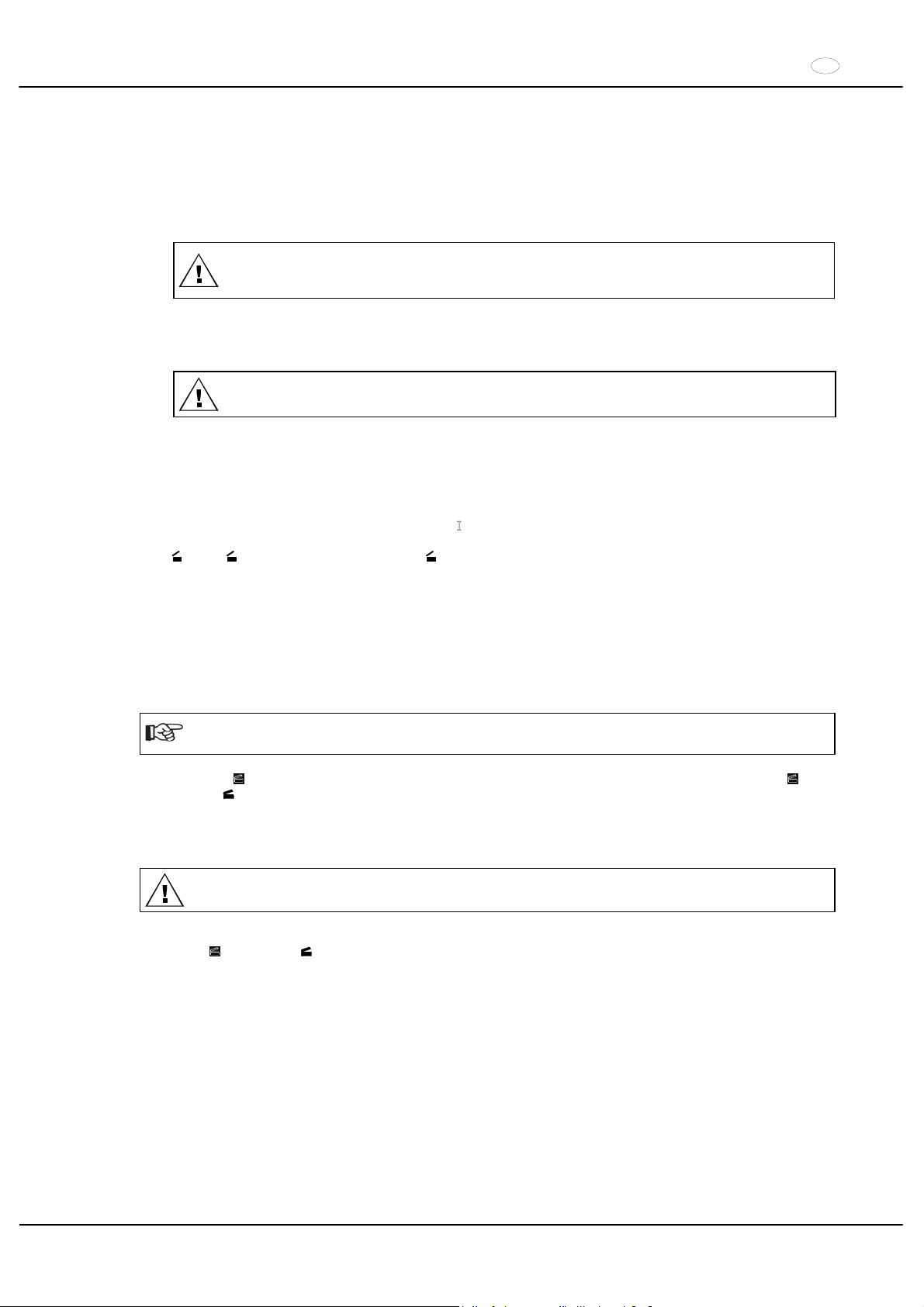
Der Deckel lässt sich nur öffnen, wenn die Zentrifuge eingeschaltet ist und der Rotor stillsteht.
Sollte dies nicht möglich sein, siehe Kapitel "Notentriegelung".
xDie Taste
an der Frontblende drücken. Der Deckel entriegelt motorisch, die Beleuchtung in der Taste und
die LED
erlöschen.
9.2 Deckel schließen
Mit den Fingern nicht zwischen Deckel und Gehäuse greifen.
Den Deckel nicht zuschlagen.
xDen Deckel auflegen und die Deckelvorderkante leicht niederdrücken. Die Verriegelung erfolgt motorisch. Die
Taste
und die LED leuchten auf.
Page 12
DE
12/104
10 Ein- und Ausbau des Rotors
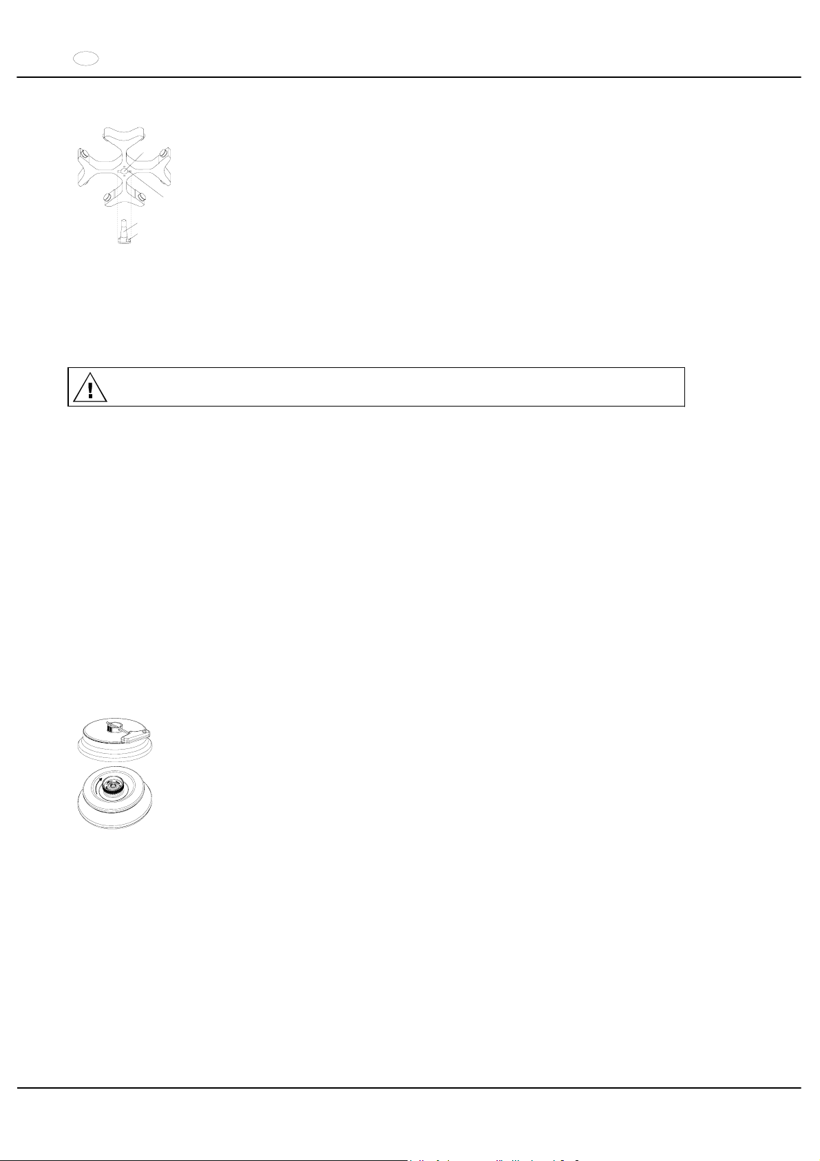
A
B
C
D
xDie Motorwelle (C) und die Bohrung des Rotors (A) reinigen und anschließend die
Motorwelle leicht einfetten. Schmutzpartikel zwischen der Motorwelle und dem Rotor
verhindern einen einwandfreien Sitz des Rotors und verursachen einen unruhigen Lauf.
xDen Rotor vertikal auf die Motorwelle aufsetzen. Der Mitnehmer der Motorwelle (D)
muss sich in der Nut des Rotors (B) befinden. Auf dem Rotor ist die Ausrichtung der Nut
gekennzeichnet.
xDie Spannmutter des Rotors mit dem mitgelieferten Schlüssel durch Drehen im
Uhrzeigersinn anziehen.
xDen Rotor auf festen Sitz prüfen.
xLösen des Rotors: Die Spannmutter durch Drehen entgegen dem Uhrzeigersinn lösen
und bis zum Abhebe-Druckpunkt drehen. Nach Überwindung des Abhebe-Druckpunkts
löst sich der Rotor vom Konus der Motorwelle. Die Spannmutter drehen, bis sich der
Rotor von der Motorwelle abheben lässt.
11 Beladen des Rotors
Standard-Zentrifugiergefäße aus Glas sind belastbar bis RZB 4000 (DIN 58970 Teil 2).
xDen Rotor auf festen Sitz prüfen.
xBei Ausschwingrotoren müssen alle Plätze des Rotors mit gleichen Gehängen besetzt sein. Bestimmte
Gehänge sind mit der Nummer des Rotorplatzes gekennzeichnet. Diese Gehänge dürfen nur in den
entsprechenden Platz des Rotors eingesetzt werden.
xDie Rotoren und Gehänge dürfen nur symmetrisch beladen werden. Zugelassene Kombinationen siehe Kapitel
"Anhang/Appendix, Rotoren und Zubehör/Rotors and accessories".
Bei Winkelrotoren müssen alle möglichen Plätze des Rotors beladen werden, siehe Kapitel "Anhang/Appendix,
Rotoren und Zubehör/Rotors and accessories".
xAuf bestimmten Gehängen ist das Gewicht der maximalen Beladung und das maximale Gewicht des komplett
bestückten Gehänges angegeben. Diese Gewichte dürfen nicht überschritten werden. Die Gewichtsangabe der
maximalen Beladung umfasst das Gesamtgewicht von Reduzierung, Gestell, Zentrifugiergefäß und Inhalt.
xBei Behältern mit Gummieinlagen muss sich unter den Zentrifugiergefäßen immer die gleiche Anzahl von
Gummieinlagen befinden.
xDie Zentrifugiergefäße immer außerhalb der Zentrifuge befüllen.
xEs darf beim Füllen und beim Ausschwingen der Gehänge keine Flüssigkeit in den Schleuderraum gelangen.
xDie vom Hersteller angegebene maximale Füllmenge der Zentrifugiergefäße darf nicht überschritten werden.
xUm die Gewichtsunterschiede innerhalb der Zentrifugiergefäße möglichst gering zu halten, ist auf eine
gleichmäßige Füllhöhe in den Gefäßen zu achten.
12 Winkelrotoren aerosoldicht verschließen
Um Aerosoldichtigkeit zu gewährleisten, muss der Deckel eines aerosoldichten Winkelrotors
fest verschlossen werden.
Das geschieht mit Hilfe des mitgelieferten Schlüssels, der durch die Bohrung im Drehgriff
gesteckt wird. Besitzt der Drehgriff keine Bohrung, muss der Deckel von Hand, durch
Drehen im Uhrzeigersinn, fest verschlossen werden.
Lieferbare aerosoldichte Winkelrotoren siehe Kapitel "Anhang/Appendix, Rotoren und
Zubehör/Rotors and accessories".
Page 13

DE
13/104
13 Bedien- und Anzeigeelemente
Siehe Abbildung auf Seite 2.
Fig. 2, Fig. 3: Anzeige- und Bedienfeld
13.1 Symbole des Bedienfeldes
Unwuchtanzeige. Die Unwuchtanzeige leuchtet, wenn der zulässige Gewichtsunterschied innerhalb der
Beladung des Rotors überschritten wurde.
Rotationsanzeige. Die Rotationsanzeige leuchtet während des Zentrifugationslaufes, solange der Rotor
dreht.
Deckelanzeige. Die Deckelanzeige leuchtet wenn der Deckel geschlossen und verriegelt ist. Während des
Zentrifugationslaufes erlischt die Deckelanzeige.
Bedienfehler bzw. auftretende Störungen werden im Display symbolisiert (siehe Kapitel "Störungen").
13.2 Tasten des Bedienfeldes
Wähltaste zum Anwählen der einzelnen Parameter.
Durch jeden weiteren Tastendruck wird der nachfolgende Parameter angewählt.
Durch Drücken der Pfeiltasten wird der Wert eines zuvor angewählten Parameters erhöht oder verkleinert.
Bei Gedrückthalten einer Pfeiltaste erhöht oder verkleinert sich der Wert mit zunehmender Geschwindigkeit.
START
Zentrifugationslauf starten. Die Rotationsanzeige
leuchtet.
Übernahme von Eingaben und Änderungen.
STOP
Zentrifugationslauf beenden.
Der Rotor läuft mit vorgewählter Bremsstufe aus. Die LED in der Taste leuchtet bis der Rotor stillsteht.
Zweimaliges Drücken der Taste löst den NOT-STOP aus.
RCF
Anwählen der RCF-Anzeige.
Die LED in der Taste leuchtet.
IMPULS
Kurzzeitzentrifugation.
Der Zentrifugationslauf erfolgt, solange die Taste gedrückt gehalten wird.
PROG
Speichern und Abrufen von Programmen.
Durch jeden weiteren Tastendruck wird das nachfolgende Programm angezeigt (1 - 2 - 3 - #)
13.3 Einstellmöglichkeiten
t/min Einstellbar von 1 - 99 min, in 1 min-Schritten.
t/sec Einstellbar von 1 - 59 s, in 1 Sekunden-Schritten.
Dauerlauf "f".
RPM Drehzahl. Einstellbar ist ein Zahlenwert von 500 RPM bis zur maximalen Drehzahl des Rotors. Maximale
Drehzahl des Rotors siehe Kapitel "Anhang/Appendix, Rotoren und Zubehör/Rotors and accessories“.
Einstellbar von 500 RPM bis 10000 RPM in 10er Schritten und ab 10000 RPM bis zur maximalen Drehzahl
in 100er Schritten.
RAD/mm Zentrifugierradius. Eingabe in mm. Zentrifugierradius siehe Kapitel "Anhang/Appendix, Rotoren und
Zubehör/Rotors and accessories". Die Eingabe des Radius ist nur möglich, wenn die RCF-Anzeige
angewählt ist (LED in der Taste
RCF
leuchtet).
RCF Relative Zentrifugalbeschleunigung. Einstellbar ist ein Zahlenwert, der eine Drehzahl zwischen 500 RPM
und der maximalen Drehzahl des Rotors ergibt. Einstellbar bis 100 in 1er Schritten und ab 100 in 10er
Schritten. Der RCF-Wert wird automatisch auf den Drehzahlschritt auf- bzw. abgerundet. Die Eingabe der
RCF ist nur möglich, wenn die RCF-Anzeige angewählt ist (LED in der Taste
RCF
leuchtet).
Anlaufstufen 1 - 9. Stufe 9 = kürzeste Anlaufzeit, Stufe 1 = längste Anlaufzeit.
Page 14
DE
14/104
Bremsstufen 0 - 9. Stufe 9 = kürzeste Auslaufzeit, Stufe 1 = lange Auslaufzeit,
Stufe 0 = längste Auslaufzeit (ungebremster Auslauf).
T/°C Temperatur-Sollwert (nur bei Zentrifuge mit Kühlung). Einstellbar von -20°C bis +40°C, in 1°C-Schritten (bei
Option Heizen/Kühlen von -20°C bis +60°C / +90°C einstellbar). Die tiefste erreichbare Temperatur ist
rotorabhängig (siehe Kapitel "Anhang/Appendix, Rotoren und Zubehör/Rotors and accessories").
PROG Programm-Nummer. Es können 3 Programme gespeichert werden (Programmplätze 1 - 2 - 3). Der
Programmplatz # dient als Zwischenspeicher für geänderte Einstellungen.
14 Zentrifugations–Parameter eingeben
Wird nach der Anwahl oder während der Eingabe von Parametern 8 Sekunden lang keine Taste gedrückt,
werden in der Anzeige wieder die vorherigen Werte angezeigt. Die Eingabe der Parameter muss dann erneut
durchgeführt werden.
xMit der Taste
RCF
die RPM- oder RCF-Anzeige anwählen. Ist die RCF-Anzeige angewählt, so leuchtet die LED
in der Taste
RCF
.
xMit der Taste
die gewünschten Parameter anwählen und mit den Tasten einstellen.
Um den Dauerlauf einzustellen müssen die Parameter t/min und t/sec mit der Taste
auf Null gestellt werden.
Der Dauerlauf wird in der Anzeige durch das Symbol "f
" angezeigt.
xNach der Eingabe aller Parameter die Taste
START
drücken, um die Einstellungen auf Programmplatz # zu
speichern. Als Bestätigung wird kurzzeitig
ok angezeigt.
Die Daten auf Programmplatz # werden bei jeder Eingabe von Parametern und Drücken der Taste
START
überschrieben.
15 Programmierung
15.1 Programm-Eingabe / -Änderung
xMit der Taste
RCF
die RPM- oder RCF-Anzeige anwählen. Ist die RCF-Anzeige angewählt, so leuchtet die LED
in der Taste
RCF
.
xMit der Taste
die gewünschten Parameter anwählen und mit den Tasten einstellen.
xMit der Taste
den Parameter PROG anwählen und mit den Tasten den gewünschten Programmplatz
einstellen. Die LED in der Taste
PROG
leuchtet.
xDie Taste
PROG
drücken, um die Einstellungen auf dem gewünschten Programmplatz zu speichern. Als
Bestätigung wird kurzzeitig
ok angezeigt.
15.2 Programm-Abruf
xDen gewünschten Programmplatz durch Drücken der Taste
PROG
anwählen.
Die Zentrifugations-Daten des angewählten Programmplatzes werden angezeigt.
xDie Parameter können durch Drücken der Taste
überprüft werden.
Page 15
DE
15/104
16 Zentrifugation
Während eines Zentrifugationslaufes dürfen sich gemäß IEC 61010-2-020, in einem Sicherheitsbereich von
300 mm um die Zentrifuge herum, keine Personen, Gefahrstoffe und Gegenstände befinden.
Wird der zulässige Gewichtsunterschied innerhalb der Beladung des Rotors überschritten, schaltet der Antrieb
während des Anlaufs ab, die Unwuchtanzeige leuchtet auf und IMBALANCE wird angezeigt.
Ist die Drehzahl im angewählten Programm höher als die maximale Drehzahl des Rotors, kann kein
Zentrifugationslauf gestartet werden. Es wird N > ROTOR MAX angezeigt (siehe Kapitel "Störungen").
Ein Zentrifugationslauf kann jederzeit durch Drücken der Taste
STOP
abgebrochen werden.
Während des Zentrifugationslaufes können alle Parameter angewählt und geändert werden (siehe Kapitel
"Zentrifugations–Parameter eingeben").
Mit der Taste
RCF
kann jederzeit zwischen der RPM- und RCF-Anzeige umgeschaltet werden. Wird mit der
RCF-Anzeige gearbeitet, ist die Eingabe des Zentrifugierradius notwendig.
Wird
OPEN OEFFNEN angezeigt, so ist eine weitere Bedienung der Zentrifuge erst nach einmaligem
Öffnen des Deckels möglich.
Wird R xx n-max xxxxx angezeigt, so hat kein Zentrifugationslauf stattgefunden, weil zuvor der Rotor
gewechselt wurde, siehe Kapitel "Rotor-Erkennung".
xDen Netzschalter einschalten. Schalterstellung ,.
xDen Rotor beladen und den Zentrifugendeckel schließen.
16.1 Zentrifugation mit Zeitvorwahl
xZeit einstellen oder ein Programm mit Zeitvorwahl abrufen (siehe Kapitel "Zentrifugations–Parameter eingeben"
oder "Programm-Abruf").
xDie Taste
START
drücken. Die Rotationsanzeige leuchtet solange der Rotor dreht.
xNach Ablauf der Zeit oder bei Abbruch des Zentrifugationslaufes durch Drücken der Taste
STOP
, erfolgt der
Auslauf mit der angewählten Bremsstufe. Die Bremsstufe wird angezeigt.
Während des Zentrifugationslaufes werden die Drehzahl des Rotors oder der daraus resultierende RCF-Wert, die
Proben-Temperatur (nur bei Zentrifuge mit Kühlung), und die verbleibende Zeit angezeigt.
16.2 Dauerlauf
xSymbol f einstellen oder ein Dauerlauf-Programm abrufen (siehe Kapitel "Zentrifugations–Parameter eingeben"
oder "Programm-Abruf").
xDie Taste
START
drücken. Die Rotationsanzeige leuchtet solange der Rotor dreht. Die Zeitzählung beginnt bei
00:00.
xDie Taste
STOP
drücken um den Zentrifugationslauf zu beenden. Der Auslauf erfolgt mit der angewählten
Bremsstufe. Die Bremsstufe wird angezeigt.
Während des Zentrifugationslaufes werden die Drehzahl des Rotors oder der daraus resultierende RCF-Wert, die
Proben-Temperatur (nur bei Zentrifuge mit Kühlung), und die gelaufene Zeit angezeigt.
16.3 Kurzzeitzentrifugation
xDie Taste
IMPULS
gedrückt halten. Die Rotationsanzeige leuchtet solange der Rotor dreht.
xDie Taste
IMPULS
wieder loslassen um den Zentrifugationslauf zu beenden. Der Auslauf erfolgt mit der
angewählten Bremsstufe. Die Bremsstufe wird angezeigt.
Während des Zentrifugationslaufes werden die Drehzahl des Rotors oder der daraus resultierende RCF-Wert, die
Proben-Temperatur (nur bei Zentrifuge mit Kühlung), und die gelaufene Zeit angezeigt.
17 Not-Stop
xDie Taste
STOP
2x drücken.
Beim Not-Stop erfolgt der Auslauf mit Bremsstufe 9 (kürzeste Auslaufzeit). Die Bremsstufe 9 wird angezeigt.
War die Bremsstufe 0 vorgewählt, so ist die Auslaufzeit technisch bedingt länger als mit Bremsstufe 9.
Page 16
DE
16/104
18 Akustisches Signal
Das akustische Signal ertönt:
xbei Auftreten einer Störung im 2 s-Intervall.
xnach Beendigung des Zentrifugationslaufes und Stillstand des Rotors im 30 s-Intervall.
Durch Öffnen des Deckels oder Drücken einer beliebigen Taste wird das akustische Signal beendet.
Das Signal nach Beendigung des Zentrifugationslaufes kann, bei Stillstand des Rotors, folgendermaßen aktiviert
oder deaktiviert werden:
xDie Taste
8 s gedrückt halten.
Nach 8 s erscheint SOUND / BELL in der Anzeige.
xMit der Taste
oder OFF (aus) oder ON (ein) einstellen.
xDie Taste
START
drücken um die Einstellung zu speichern.
Als Bestätigung wird kurzzeitig
ok angezeigt.
19 Betriebsstunden-Abfrage
Die Abfrage der Betriebsstunden ist nur bei Stillstand des Rotors möglich.
xDie Taste
8 s gedrückt halten.
Nach 8 s erscheint SOUND / BELL in der Anzeige.
xDie Taste
nochmals drücken.
Die Betriebsstunden (CONTROL: ) der Zentrifuge werden angezeigt.
xZum Verlassen der Betriebsstunden-Abfrage die Taste
oder drücken.
20 Kühlung (nur bei Zentrifuge mit Kühlung)
Der Temperatur-Sollwert kann von -20°C bis +40°C eingestellt werden. Bei Zentrifugen mit Option Heizen/Kühlen ist
der Temperatur-Sollwert von -20°C bis +60°C / +90°C einstellbar. Die tiefste erreichbare Temperatur ist
rotorabhängig (siehe Kapitel "Anhang/Appendix, Rotoren und Zubehör/Rotors and accessories").
20.1 Standby-Kühlung
Bei Stillstand des Rotors und geschlossenem Deckel wird der Schleuderraum auf die vorgewählte Temperatur
gekühlt. Im Display wird der Temperatur-Sollwert angezeigt.
20.2 Vorkühlen des Rotors
Zum schnellen Vorkühlen des unbeladenen Rotors und des Zubehörs, empfiehlt sich ein Zentrifugationslauf mit den
Einstellungen Dauerlauf und einer Drehzahl von ca. 20% der maximalen Drehzahl des Rotors.
21 Heizung (nur bei Zentrifuge mit Option Heizen/Kühlen)
Während des Zentrifugationslaufes wird bei Bedarf der Schleuderraum auf die vorgewählte Temperatur geheizt. Bei
Stillstand des Rotors ist die Heizung ausgeschaltet.
Verbrennungsgefahr! Die Oberflächen-Temperatur des Heizelements im Schleuderraum der Zentrifuge
kann bis zu 500°C / 932°F betragen. Das Heizelement nicht berühren.
Das Kunststoff-Nutgehänge Best.-Nr. 5091 darf nur bei Temperaturen bis maximal 40°C verwendet
werden.
Page 17
DE
17/104
22 Relative Zentrifugalbeschleunigung (RCF)
Die relative Zentrifugalbeschleunigung (RCF) wird als Vielfaches der Erdbeschleunigung (g) angegeben. Sie ist ein
einheitsfreier Zahlenwert und dient zum Vergleich der Trenn- und Sedimentationsleistung.
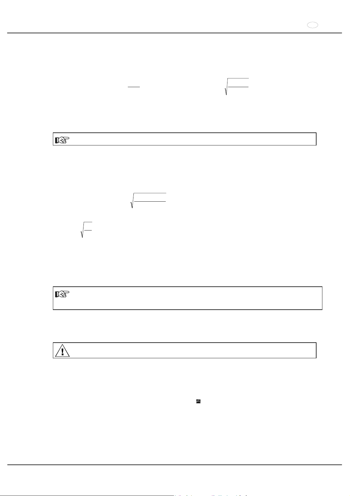
Die Berechnung erfolgt nach der Formel:
1,118r
2
1000
RPM
RCF uu
¸
¹
·
¨
©
§
1000
1,118r
RCF
RPM u
u
RCF = Relative Zentrifugalbeschleunigung
RPM = Drehzahl
r = Zentrifugierradius in mm = Abstand von der Mitte der Drehachse bis zum Zentrifugiergefäßboden.
Zentrifugierradius siehe Kapitel "Anhang/Appendix, Rotoren und Zubehör/
Rotors and accessories".
Die relative Zentrifugalbeschleunigung (RCF) ist abhängig von der Drehzahl und dem Zentrifugierradius.
23 Zentrifugation von Stoffen mit höherer Dichte
Die Rotoren sind so konstruiert, dass sie bei angegebener Nenndrehzahl Stoffe mit einer durchschnittlichen
homogenen Dichte von max. 1,2 kg/dm3 zentrifugieren können. Stoffe mit einer höheren Dichte müssen mit
reduzierter Drehzahl zentrifugiert werden.
Die erlaubte Drehzahl lässt sich nach folgender Formel berechnen:
hlNenndrehza
Dichtehöhere
1,2
)(nDrehzahlReduzierte
red u
z.B.: RPM 4000, Dichte 1,6 kg/dm
3
RPM34644000
1,6
1,2
nred u
Bei eventuellen Unklarheiten ist Auskunft beim Hersteller einzuholen.
24 Rotor-Erkennung
Nach jedem Start eines Zentrifugationslaufes wird der eingesetzte Rotor erkannt.
Nach einem Rotorwechsel schaltet der Antrieb ab und der Rotorcode (R xx) sowie die maximale Drehzahl
(n-max=xxxxx) des Rotors werden angezeigt.
Eine weitere Bedienung der Zentrifuge ist erst nach einmaligem Öffnen des Deckels möglich.
Wenn nach einem Rotorwechsel die maximale Drehzahl des Rotors kleiner als die eingestellte Drehzahl ist,
wird die Drehzahl auf die maximale Drehzahl des Rotors begrenzt.
25 Notentriegelung
Bei einem Stromausfall kann der Deckel nicht motorisch entriegelt werden. Es muss eine Notentriegelung von Hand
durchgeführt werden.
Zur Notentriegelung die Zentrifuge vom Netz trennen.
Den Deckel nur bei Stillstand des Rotors öffnen.
Siehe Abbildung auf Seite 2.
xDen Netzschalter ausschalten (Schalterstellung "0").
xDurch das Fenster im Deckel schauen, um sich zu vergewissern, dass der Rotor stillsteht.
xDen Sechskant-Stiftschlüssel waagerecht in die Bohrung (Fig. 1, A) einführen und vorsichtig eine halbe
Umdrehung im Uhrzeigersinn drehen, bis sich der Deckel öffnen lässt.
xDen Sechskant-Stiftschlüssel wieder aus der Bohrung herausziehen.
xNach dem Wiedereinschalten der Zentrifuge die Taste
drücken, dass die motorische Deckelverriegelung
wieder die Grundstellung (geöffnet) einnimmt.
Page 18
DE
18/104
26 Pflege und Wartung
Vor der Reinigung den Netzstecker ziehen.
Bevor ein anderes als das vom Hersteller empfohlene Reinigungs- oder Dekontaminationsverfahren
angewandt wird, hat sich der Benutzer beim Hersteller zu vergewissern, dass das vorgesehene Verfahren
das Gerät nicht schädigt.
xEs sind Reinigungs- oder Desinfektionsmittel zu verwenden, die im pH-Bereich 5 - 8 liegen. Alkalische
Reinigungsmittel mit einem pH-Wert > 8 sind zu vermeiden.
xUm Korrosionserscheinungen durch Reinigungs- oder Desinfektionsmittel zu vermeiden sind die speziellen
Anwendungshinweise vom Hersteller des Reinigungs- oder Desinfektionsmittels unbedingt zu beachten.
26.1 Zentrifuge
xDas Gehäuse der Zentrifuge und den Schleuderraum regelmäßig säubern und bei Bedarf mit Seife oder einem
milden Reinigungsmittel und einem feuchten Tuch reinigen. Dies dient zum einen der Hygiene und es verhindert
Korrosion durch anhaftende Verunreinigungen.
xBei Bildung von Kondenswasser den Schleuderraum, durch Auswischen mit einem saugfähigen Tuch, trocknen.
xGelangt infektiöses Material in den Schleuderraum, so ist dieser umgehend zu desinfizieren. Zur Flächen-
Desinfektion empfehlen wir Bacillol® Plus von der Firma Bode Chemie Hamburg oder Biocidal ZF
TM
von der
Firma WAK-Chemie Medical GmbH Steinbach.
xDie Gummidichtung des Schleuderraums nach jeder Reinigung leicht einfetten.
26.2 Rotoren und Zubehör
xUm einer Korrosion und Materialveränderungen vorzubeugen müssen die Rotoren und die Zubehörteile
regelmäßig mit Seife oder einem milden Reinigungsmittel und einem feuchten Tuch gereinigt werden. Die
Reinigung wird mindestens einmal wöchentlich, noch besser nach jedem Gebrauch empfohlen.
xSind die Rotoren oder die Zubehörteile durch pathogenes oder radioaktives Material verunreinigt, so muss eine
geeignete Reinigung durchgeführt werden. Zur Desinfektion empfehlen wir Helipur
®
H plus N von der Firma B.
Braun Melsungen. Zum Entfernen von radioaktivem Material empfehlen wir decon neutracon® von der Firma
Decon Laboratories Limited.
xDie Rotoren und Zubehörteile müssen unmittelbar nach der Reinigung getrocknet werden.
xWinkelrotoren, Behälter und Gehänge aus Aluminium sind nach dem Trocknen mit säurefreiem Fett z.B.
Vaseline leicht einzufetten.
xBei aerosoldichten Rotoren und Bio-Sicherheitssystemen (siehe Kapitel "Anhang/Appendix, Rotoren und
Zubehör/Rotors and accessories") sind die Dichtungsringe regelmäßig (wöchentlich) zu prüfen und zu reinigen.
Bei Anzeichen von Rissbildung, Versprödung oder Abnutzung ist der Dichtungsring sofort auszutauschen. Um
ein Verdrehen des Dichtungsringes während dem Öffnen und Schließen des Deckels zu vermeiden, muss der
Dichtungsring mit säurefreiem Fett z.B. Vaseline leicht eingefettet werden.
xUm Korrosion infolge Feuchtigkeit zwischen Rotor und Motorwelle zu verhindern, sollte der Rotor mindestens
einmal im Monat ausgebaut, gereinigt und die Motorwelle leicht gefettet werden.
xDie Rotoren und die Zubehörteile sind monatlich auf Korrosionsschäden zu überprüfen.
Rotoren und Zubehör dürfen bei Anzeichen von Verschleiß oder Korrosion nicht mehr verwendet werden.
xDen Rotor wöchentlich auf festen Sitz prüfen.
26.2.1 Tragzapfen
Bei Ausschwingrotoren müssen die Tragzapfen regelmäßig gefettet werden (Hettich-Schmierfett Nr. 4051), um ein
gleichmäßiges Ausschwingen der Gehänge zu gewährleisten.
26.2.2 Rotoren und Zubehör mit begrenzter Verwendungsdauer
Die Verwendung von bestimmten Rotoren, Gehängen und Zubehörteilen ist zeitlich begrenzt.
Diese sind mit dem Ablaufdatum gekennzeichnet, z.B.: "einsetzbar bis Ende: / usable until end of: ,V. Quartal 2011".
Die Rotoren, Gehänge und Zubehörteile dürfen aus Sicherheitsgründen nicht mehr verwendet werden,
wenn das darauf gekennzeichnete Ablaufdatum erreicht ist.
Page 19
DE
19/104
26.3 Autoklavieren
Ausschwingrotoren, Winkelrotoren aus Aluminium, Gehänge aus Metall, Deckel mit Bioabdichtung sowie Gestelle
und Reduzierungen können bei 121°C / 250°F (20 min) autoklaviert werden.
Im Zweifelsfall muss beim Hersteller nachgefragt werden.
Die Deckel der Rotoren und Behälter müssen vor dem Autoklavieren abgenommen werden.
Das Autoklavieren beschleunigt den Alterungsprozess von Kunststoffen. Außerdem kann es bei
Kunststoffen Farbveränderungen verursachen.
Wir empfehlen nach dem Autoklavieren die Dichtungsringe von aerosoldichten Rotoren und Bio-
Sicherheitssystemen auszutauschen.
26.4 Zentrifugiergefäße
xBei Undichtigkeit oder nach dem Bruch von Zentrifugiergefäßen, sind zerbrochene Gefäßteile, Glassplitter und
ausgelaufenes Zentrifugiergut vollständig zu entfernen.
xDie Gummieinlagen sowie die Kunststoff-Hülsen der Rotoren sind nach einem Glasbruch zu ersetzen.
Verbleibende Glassplitter verursachen weiteren Glasbruch !
xHandelt es sich um infektiöses Material so ist umgehend eine Desinfektion durchzuführen.
Page 20
DE
20/104
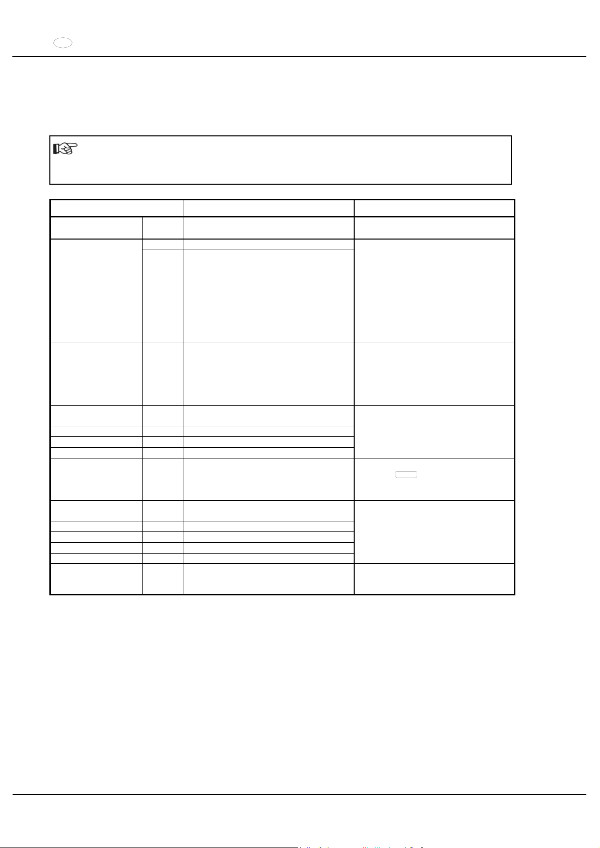
27 Störungen
Lässt sich der Fehler laut Störungstabelle nicht beheben, so ist der Kundendienst zu benachrichtigen.
Bitte den Zentrifugentyp und die Werknummer angeben. Beide Werte sind auf dem Typenschild der Zentrifuge
ersichtlich.
Einen NETZ-RESET durchführen:
Den Netzschalter ausschalten (Schalterstellung "0").
Mindestens 10 Sekunden lang warten und anschließend den Netzschalter wieder einschalten
(Schalterstellung ",").
Anzeige Ursache Beseitigung
keine Anzeige --- keine Spannung.
Auslösen der Überstromschutzsicherung.
Versorgungsspannung überprüfen.
Netzschalter EIN.
01 Tacho defekt. TACHO - ERROR
02 Kein Rotor eingebaut.
Motor, Umrichter, Antrieb defekt.
Deckel öffnen.
Den Netzschalter ausschalten
(Schalterstellung "0").
Mindestens 10 Sekunden lang
warten.
Den Rotor von Hand kräftig drehen.
Den Netzschalter wieder
einschalten (Schalterstellung ",").
Während des Einschaltens muss
sich der Rotor drehen
IMBALANCE --- Der Rotor ist ungleichmäßig beladen.
Deckel öffnen.
Die Beladung des Rotors über-
prüfen, siehe Kapitel "Beladen des
Rotors".
Den Zentrifugationslauf wieder-
holen.
CONTROL - ERROR 04,
06 - 09
Fehler Deckelverriegelung
N > MAX 05 Überdrehzahl
N < MIN 13 Unterdrehzahl
ROTORCODE 10 Fehler Rotorcodierung
Einen NETZ-RESET durchführen.
MAINS INTERRUPT --- Netzunterbrechung während des Zentrifu-
gationslaufes. (Der Zentrifugationslauf
wurde nicht beendet.)
Deckel öffnen.
Taste
START
drücken.
Bei Bedarf den Zentrifugationslauf
wiederholen.
VERSIONS-ERROR 12 Keine Übereinstimmung der Elektronik-
Komponenten
CONTROL-ERROR 21 - 27 Fehler / Defekt Steuerteil
SER I/O - ERROR 30 - 38 Fehler / Defekt Schnittstelle
° C * - ERROR 50 - 56 Fehler / Defekt Kühlung
FU / CCI - ERROR 60 - 83 Fehler / Defekt Motorsteuerung
Einen NETZ-RESET durchführen.
N > ROTOR MAX --- Drehzahl im angewählten Programm
größer als die maximale Drehzahl des
Rotors.
Drehzahl überprüfen und
korrigieren.
Page 21
DE
21/104
28 Reparaturannahme von Zentrifugen
Wird die Zentrifuge zur Reparatur an den Hersteller zurückgesandt, so muss diese, zum Schutz von Personen,
Umwelt und Material, vor dem Versand dekontaminiert und gereinigt werden.
Eine Annahme von kontaminierten Zentrifugen behalten wir uns vor.
Anfallende Kosten für Reinigungs- und Desinfektionsmaßnahmen werden dem Kunden in Rechnung gestellt.
Wir bitten dafür um Ihr Verständnis.
29 Entsorgung
Bei der Entsorgung des Geräts sind die jeweiligen gesetzlichen Vorschriften zu beachten.
Gemäß der Richtlinie 2002/96/EG (WEEE) dürfen alle nach dem 13.08.2005 gelieferten Geräte nicht mehr mit dem
Hausmüll entsorgt werden. Das Gerät gehört zur Gruppe 8 (Medizinische Geräte) und ist in den Business-toBusiness-Bereich eingeordnet.
Mit dem Symbol des durchgestrichenen Abfalleimers wird darauf hingewiesen, dass das Gerät nicht mit
dem Hausmüll entsorgt werden darf.
Die Entsorgungsvorschriften der einzelnen EU-Länder können unterschiedlich sein. Im Bedarfsfall
wenden Sie sich bitte an Ihren Lieferanten.
Page 22

EN
22/104
Contents
1 Use according to specification ..............................................................................................................................24
2 Residual risks .......................................................................................................................................................24
3 Technical specifications........................................................................................................................................ 24
4 Notes on safety.....................................................................................................................................................26
5 Symbol meanings .................................................................................................................................................27
6 Delivery checklist..................................................................................................................................................27
7 Unpacking the centrifuge......................................................................................................................................27
8 Initial operation .....................................................................................................................................................28
9 Opening and closing the lid ..................................................................................................................................28
9.1 Opening the lid .............................................................................................................................................. 28
9.2 Closing the lid................................................................................................................................................ 28
10 Installation and removal of the rotor ..................................................................................................................29
11 Loading the rotor ...............................................................................................................................................29
12 Aerosol tight sealing of angle rotors ..................................................................................................................29
13 Control and display elements ............................................................................................................................ 29
13.1 Control panel symbols ............................................................................................................................... 29
13.2 Control panel pushbuttons (keys) ..............................................................................................................30
13.3 Adjustment possibilities..............................................................................................................................30
14 Entering centrifugation parameter ..................................................................................................................... 31
15 Programming.....................................................................................................................................................31
15.1 Programme input/alteration........................................................................................................................31
15.2 Programme recall.......................................................................................................................................31
16 Centrifugation.................................................................................................................................................... 31
16.1 Centrifugation with pre-set time .................................................................................................................31
16.2 Continuous run...........................................................................................................................................32
16.3 Short-term centrifugation ........................................................................................................................... 32
17 Emergency Stop................................................................................................................................................ 32
18 Acoustic Signal.................................................................................................................................................. 32
19 Recall hours of operation .................................................................................................................................. 32
20 Cooling (only in centrifuges with cooling) .......................................................................................................... 32
20.1 Standby-cooling .........................................................................................................................................32
20.2 Pre-cooling the rotor .................................................................................................................................. 32
21 Heating (only on centrifuges with heating/cooling option) .................................................................................33
22 Relative centrifugal force (RCF) ........................................................................................................................ 33
23 Centrifugation of materials with higher density..................................................................................................33
24 Rotor Identification ............................................................................................................................................ 33
25 Emergency release ........................................................................................................................................... 34
26 Maintenance and servicing................................................................................................................................34
26.1 Centrifuge .................................................................................................................................................. 34
26.2 Rotors and Attachments ............................................................................................................................ 34
26.2.1 Trunnions............................................................................................................................................34
26.2.2 Rotors and accessories with limited term of use.................................................................................35
26.3 Autoclaving ................................................................................................................................................ 35
Page 23

EN
23/104
26.4 Centrifuge containers.................................................................................................................................35
27 Faults ................................................................................................................................................................36
28 Acceptance of the centrifuges for repair............................................................................................................36
29 Disposal ............................................................................................................................................................36
30
Anhang / Appendix ............................................................................................................................................69
30.1 Rotoren und Zubehör / Rotors and accessories.........................................................................................69
Page 24
EN
24/104
1 Use according to specification
The machine presented here is a medical product (laboratory centrifuge) according to the IVD guideline 98/79/EG.
The centrifuge is used to separate substances or substance mixtures with a density of max. 1.2 kg/dm³. This also
includes substances and substance mixtures of human origin. The centrifuge is only intended to be used for this
purpose. A different use or application over and above this is deemed not in accordance with the specifications. The
company Andreas Hettich GmbH & Co. KG undertakes no liability for damages resulting therefrom.
Belonging to the application according to specification is also the observance of all references contained in the
Instruction Manual and compliance with the inspection and maintenance works.
2 Residual risks
The machine is constructed according to the state of the art and the recognized technical safety regulations.
Improper use and handling can result in dangers to life and limb of the user or third parties and impairments to the
machine or to other material assets. The machine is only to be used for the specified applications and only in an
impeccable technical safety condition.
Disturbances that can interfere with the safety are to be immediately rectified.
3 Technical specifications
Manufacturer
Andreas Hettich GmbH & Co. KG
D-78532 Tuttlingen
Model ROTANTA 460
Type 5600 5600-01
Mains voltage (r 10%) 208-240 V 1a
110-127 V 1~
Mains frequency 50 - 60 Hz 50 - 60 Hz
Connected load 1500 VA 1300 VA
Current consumption 6.5 A 11 A
Cooling medium ---Max. capacity 4 x 750 ml
Allowed density
1.2 kg/dm
3
Speed (RPM) 15000
Force (RCF) 24400
Kinetic energy 41000 Nm
Obligatory inspection (BGR 261) yes
Ambient conditions (EN 61010-1)
Set-up site
Indoors only
Altitude
Up to 2000 m above sea level
Ambient temperature
2°C to 40°C
Humidity
Maximum relative humidity 80% for temperatures up to 31°C, linearly
decreasing to 50% relative humidity at 40°C.
Excess-voltage category
(IEC 60364-4-443)
,,
Pollution degree
2
Device protection class
,
Not suitable for use in explosion-endangered areas.
EMC
Emitted interference (suppression
of radio interference)
EN 55011,
Group 1, Class B
EN 61000-3-3
FCC Class A
Interference immunity
EN 61000-6-1 ----
Noise level (dependent on rotor)
d 67 dB(A)
Dimensions
Width
554 mm
Depth
707 mm
Height
453 mm
Weight 106 kg 115 kg
Page 25
EN
25/104
Manufacturer
Andreas Hettich GmbH & Co. KG
D-78532 Tuttlingen
Model ROTANTA 460 R
Type
5605,
5605-20
5605-50
5605-07
5605-01,
5605-51
Mains voltage (r 10%) 208-240 V 1a
208-240 V 1~ 110-127 V 1~
Mains frequency 50 - 60 Hz 60 Hz 60 Hz
Connected load 2400 VA 2200 VA 2000 VA
Current consumption 10 A 10 A 16 A
Cooling medium R 404A
Max. capacity 4 x 750 ml
Allowed density
1.2 kg/dm
3
Speed (RPM) 15000
Force (RCF) 24400
Kinetic energy 51000 Nm
Obligatory inspection (BGR 261) yes
Ambient conditions (EN 61010-1)
Set-up site
Indoors only
Altitude
Up to 2000 m above sea level
Ambient temperature
5°C to 35°C
Humidity
Maximum relative humidity 80% for temperatures up to 31°C, linearly
decreasing to 50% relative humidity at 40°C.
Excess-voltage category
(IEC 60364-4-443)
,,
Pollution degree
2
Device protection class
,
Not suitable for use in explosion-endangered areas.
EMC
Emitted interference (suppression
of radio interference)
EN 55011,
Group 1, Class B
EN 61000-3-3
FCC Class A
Interference immunity
EN 61000-6-1 ----
Noise level (dependent on rotor)
d 64 dB(A)
Dimensions
Width
770 mm
Depth
707 mm
Height
453 mm
Weight 147 kg 156 kg
Page 26

EN
26/104
4 Notes on safety
No claim under guarantee will be considered by the manufacturer unless the above instructions have
been adhered to.
xBefore the initial operation of your centrifuge you should read and pay attention to the operating
instructions.
Only personnel that has read and understood the operating instructions are allowed to operate the
device.
xAlong with the operating instructions and the legal regulations on accident prevention, you should also follow the
recognised professional regulations for working in a safe and professional manner.
These operating instructions should be read in conjunction with any other instructions concerning accident
prevention and environmental protection based on the national regulations of the country where the device is to
be used.
xThis centrifuge is a state-of-the-art piece of equipment which is extremely safe to operate.
However, it can lead to danger for users or others if used by untrained staff, in an inappropriate way or for a
purpose other than that it was designed for.
xThe centrifuge should be installed on a good, stable base.
xBefore using the centrifuge absolutely check the rotor for firm placement.
xWhen the centrifuge is running, according to IEC 61010-2-020, no persons, dangerous substances or objects may
be within the safety margin of 300 mm around the centrifuge.
xThe centrifuge must not be moved or knocked during operation.
xIn case of fault or emergency release, never touch the rotor before it has stopped turning.
xTo avoid damage due to condensate, when changing from a cold to a warm room the centrifuge must either heat
up for at least 3 hours in the warm room before being connected to the mains, or run hot for 30 minutes in the
cold room.
xOnly the rotors and accessories approved by the manufacturer for this device may be used (see chapter
"Anhang/Appendix, Rotoren und Zubehör/Rotors and accessories").
xThe centrifuge rotor may only be loaded in accordance with the chapter "Loading the rotor".
xWhen centrifuging with maxim revolutions per minute the density of the materials or the material mixtures may not
exceed 1.2 kg/dm
3
.
xThe centrifuge may only be operated when the balance is within the bounds of acceptability.
xThe centrifuge may not be operated in explosion-endangered areas.
xThe centrifuge must not be used with:
inflammable or explosive materials
materials that react with one another producing a lot of energy.
xIf users have to centrifuge hazardous materials or compounds contaminated with toxic, radioactive or pathogenic
micro-organisms, they must take appropriate measures.
For hazardous substances centrifuge containers with special screw caps must strictly be used. In addition to the
screw cap centrifuge containers, for materials in hazard category 3 and 4 a biosafety system must be used (see
the World Health Organisation’s “Laboratory Biosafety Manual”).
Under a biosafety system small drips and aerosols are prevented from escaping by a bioseal (packing ring)
located between the hanger and the lid.
If the hanger of a biosafety system is used without the lid, the packing ring must be removed from the hanger in
order to prevent the packing ring from being damaged during the centrifugation run. Damaged packing rings must
not be used to seal the biosafety system.
Without the use of a biosafety system the centrifuge is not microbiologically sealed in the sense of the EN
610101-2-020 standard.
For further details of available biosafety systems see chapter "Anhang/Appendix, Rotoren und Zubehör/Rotors
and accessories". If in doubt, you should obtain relevant information from the manufacturer.
xThe centrifuge must not be operated with highly corrosive substances which could impair the mechanical integrity
of rotors, hangers and accessories.
xRotors, suspensions and accessories that possess traces of corrosion or mechanical damage or if their term of
use has expired may not be used any longer.
xRepairs must only be carried out by personnel authorised to do so by the manufacturer.
xOnly original spare parts and original accessories licensed by the Andreas Hettich GmbH & Co. KG company are
allowed to be utilised.
xThe following safety regulations apply:
IEC 61010-1 and IEC 61010-2-020 as well as their national deviations.
xThe safe operation and reliability of the centrifuge can only be guaranteed if:
the centrifuge is operated in accordance with the operating instructions,
the electrical installation on the site where the centrifuge is installed conforms to the demands of IEC
stipulations,
prescribed tests to BGV A1, BGR 261 are carried out by an expert.
Page 27
EN
27/104
5 Symbol meanings
Symbol on the machine:
Attention, general hazard area.
Before using the centrifuge implicitly read the operating instructions and pay attention to the safety
relevant references!
Symbol in the operating instructions:
Attention, general hazard area.
This symbol refers to safety relevant warnings and indicates possibly dangerous situations.
The non-adherence to these warnings can lead to material damage and injury to personal.
Symbol on the machine and in the operating instructions:
Beware of hot surface.
Symbol on the machine and in the operating instructions:
The plastic buckets, order no. 5091, may only be used for temperatures up to a maximum of 40°C.
Symbol on the machine:
Equipotential: Connector (PE connector) for potential equalization (only for centrifuge with PE
connector).
Symbol in the operating instructions:
This symbol refers to important circumstances.
Symbol on the machine and in the operating instructions:
Symbol for the separate collection of electric and electronic devices according to the guideline
2002/96/EG (WEEE). The device belongs to Group 8 (medical devices).
Applies in the countries of the European Union, as well as in Norway and Switzerland.
6 Delivery checklist
1 Connecting cable
1 Hex. pin driver 2,5 mm
1 Hex. pin driver 5 mm
1 Lubricating grease for trunnions
1 Operating instructions
1 Notes on moving the equipment safely
The rotor(s) and associated accessories are included in the delivery in the quantity ordered.
7 Unpacking the centrifuge
xLift the carton upward and remove the padding.
x
Do not lift by the front panel.
Observe the weight of the centrifuge, refer to chapter "Technical specifications".
Lift the centrifuge on both sides with an appropriate number of helpers and place it on the laboratory table.
Page 28
EN
28/104
8 Initial operation
xAccording to the laboratory instrument standards IEC 61010-2-020 an emergency switch to separate power
supply in the event of a failure must be installed in the building electrical system.
This switch has to be placed remote from the centrifuge, prefered outside of the room in which the centrifuge is
installed or near by the exit of this room.
xPosition the centrifuge in a stable and level manner in a suitable place. During set-up, the required safety margin
of 300 mm around the centrifuge is to be kept according to IEC 61010-2-020.
When the centrifuge is running, according to IEC 61010-2-020, no persons, dangerous substances or
objects may be within the safety margin of 300 mm around the centrifuge.
xDo not place any object in front of the ventiduct.
Keep a ventilation area of 300 mm around the ventiduct.
xIn the case of the centrifuge, type 5605-20, connect the nitrogen supply according to the enclosed instruction
sheet AH5605-20XX.
It is mandatory that the centrifuge be connected according to the enclosed instruction sheet.
Make sure you observe the enclosed instruction sheet.
xCentrifuge with PE connector:
If required, connect the PE connector at the back of the device with an additional medical potential equalization
system.
xCheck whether the mains voltage tallies with the statement on the type plate.
xConnect the centrifuge with the connection cable to a standard mains socket. For connection ratings refer to
Chapter "Technical specifications".
xTurn on the mains switch. Switch position ",
".
The machine type and program version will be displayed and the LEDs light up.
OPEN OEFFNEN will be
displayed after 8 seconds. The LED
lights up.
xOpen the lid.
The last used centrifuge data will be displayed.
xRemove the transport safety device (see instruction sheet on “Moving the equipment safely”).
9 Opening and closing the lid
9.1 Opening the lid
The lid can only be opened when the centrifuge is switched on and the rotor is at rest. If it cannot be
opened under these circumstances, see the section on “Emergency release”.
xPress the button on the front panel. The lid unlocks via the motor, the illuminated pushbutton and the LED
extinguish.
9.2 Closing the lid
Do not put your fingers between lid and housing.
Do not bang the lid shut.
xPlace the lid and lightly press down the front edge of the lid. The locking action is effected by motor. The button
and the LED light up.
Page 29
EN
29/104
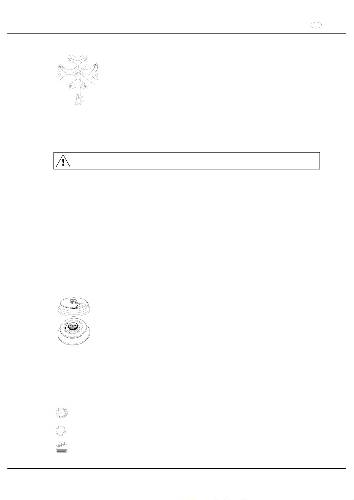
10 Installation and removal of the rotor
A
B
C
D
xClean the motor shaft (C) and the rotor drilling (A), and lightly grease the motor shaft
afterwards. Dirt particles between the motor shaft and the rotor hinder a perfect seating
of the rotor and cause an irregular operation.
xPlace the rotor vertically on the motor shaft. The motor shaft dog (D) has to fit in the
rotor slot (B). The alignment of the groove is labelled on the rotor.
xTighten the rotor tension nut with the supplied wrench by turning in a clockwise
direction.
xCheck the rotor for firm seating.
xLoosening the rotor: Loosen the tension nut by turning in a counter clockwise direction,
and turning until the working point for lifting. After passing the working point for lifting
the rotor is loosened from the motor shaft cone. Turn the tension nut until the rotor is
able to be lifted from the motor shaft.
11 Loading the rotor
Standard centrifuge containers of glass will not stand RCF values exceeding 4000 (DIN 58970, pg. 2).
xCheck the rotor for firm seating.
xWith swing-out rotors all rotor positions must be lined with identical hangers. Certain hangers are marked with
the number of the rotor position. These hangers may only be used in the respective rotor position.
xThe rotors and hangers may only be loaded symmetrically. For authorised combinations see Chapter
"Anhang/Appendix, Rotoren und Zubehör/Rotors and accessories".
In the case of angle rotors all possible rotor positions must be loaded, see chapter "Anhang/Appendix, Rotoren
und Zubehör/Rotors and accessories".
xOn certain suspensions, the weight of the maximum load and the maximum weight of the suspension when it is
fully equipped is displayed. This weight may not be exceeded. The weight specified for the maximum loading
includes the total weight of adapter, frame, centrifuging container and content.
xIn containers with rubber inserts, the same number of rubber inserts must always be among the centrifuge
containers.
xAlways fill the centrifuge containers outside of the centrifuge.
xNo liquid should be allowed to enter the centrifugal chamber during filling and swinging out of the hangers.
xThe maximum filling quantity for the centrifuge containers specified by the manufacturer must not be exceeded.
xIn order to maintain the weight differences within the centrifuge container as marginal as possible, a consistent
fill level in the containers is to be heeded.
12 Aerosol tight sealing of angle rotors
To ensure aerosol sealing the lid of an aerosol sealed angular rotor must be firmly closed.
This is performed with the help of the supplied spanner that is inserted through the borehole
in the rotary handle. If the rotary handle does not have a borehole then the lid must be firmly
closed by turning in clockwise direction.
For available aerosol tight angle rotors, please see chapter "Anhang/Appendix, Rotoren und
Zubehör/Rotors and accessories".
13 Control and display elements
See figure on page 2.
Fig. 2, Fig. 3: Display and control panel
13.1 Control panel symbols
Unbalance display. The unbalance display lights up if the permissible weight difference within the rotor
loading has been exceeded.
Rotation display. The rotation display lights up during the centrifugation run as long as the rotor is turning.
Lid display. The lid display lights up if the lid is closed and locked. During the centrifugation run the lid
display is extinguished.
Page 30

EN
30/104
Operating errors or any occurring disturbances are symbolised in the display (see Chapter "Faults").
13.2 Control panel pushbuttons (keys)
Selection control key for selection of specific parameter.
The subsequent parameter is selected by every further keystroke.
By pushing the arrow keys the value of a previously selected parameter is increased or decreased. By
keeping an arrow key depressed the value is increased or decreased with increasing speed.
START
Start the centrifugation run. The rotation display
lights up.
Acquisition of input and changes.
STOP
Stop the centrifugation run.
The rotor runs down with pre-selected brake step. The LED in the key lights up until the rotor stops.
Pushing the key twice triggers the EMERGENCY STOP.
RCF
Selecting the RCF display.
The LED in the key lights up.
IMPULS
Short-term centrifugation.
The centrifugation run is effected as long as the key is held down.
PROG
Storing and recalling programmes.
The subsequent programme is displayed by every further keystroke (1 - 2 - 3 - #).
13.3 Adjustment possibilities
t/min Adjustable from 1 - 99 min. in 1-min. intervals.
t/sec Adjustable from 1 - 59 sec. in 1-sec. intervals.
Continuous run "f".
RPM Revolutions per minute. A numerical value from 500 RPM up to the maximum speed of the rotor can be set.
Maximum speed of the rotor, see Chapter "Anhang/Appendix, Rotoren und Zubehör/Rotors and
accessories". Adjustable from 500 RPM to 10000 RPM in steps of 10 and from 10000 RPM up to the
maximum speed in steps of 100.
RAD/mm Centrifugation radius. Input in mm. For centrifugation radius see Chapter "Anhang/Appendix, Rotoren und
Zubehör/Rotors and accessories". The input of the radius is only possible if the RCF display is selected
(LED in the key
RCF
lights up).
RCF Relative Centrifugal Acceleration. A numerical value can be set, which gives a speed between 500 RPM
and the maximum speed of the rotor. Adjustable up to 100 in intervals of 1, and from 100 in intervals of 10.
The RCF value is automatically rounded up or rounded down with regard to the RPM interval. The input of
the RCF is only possible if the RCF display is selected (LED in the key
RCF
lights up).
Starting steps 1 - 9. Step 9 = shortest starting time, Step 1 = longest starting time.
Brake steps 0 - 9. Step 9 = shortest run-down time, Step 1 = long run-down time,
Step 0 = longest run-down time (brakeless run-down).
T/°C Temperature Set Point (only in centrifuges with cooling). Adjustable from -20°C to +40°C, in 1°C intervals
(heating/cooling option settable between -20°C and +60°C / +90°C). The lowest obtainable temperature
depends on the rotor (see Chapter "Anhang/Appendix, Rotoren und Zubehör/Rotors and accessories").
PROG Programme Number. 3 programmes can be stored (programme positions 1 - 2 - 3). The programme
position # serves as temporary storage for altered adjustments.
Page 31
EN
31/104
14 Entering centrifugation parameter
If no key is pressed for 8 seconds long after the selection or during the input of parameters, the previous
values will be shown in the display. The input of parameter then has to be executed again.
xSelect the RPM or RCF display with the key
RCF
. If the RCF display is selected, the LED in the key
RCF
.
lights up.
xSelect the desired parameter with the key
, and adjust with the keys .
In order to set continuous operation, the parameters t/min and t/sec must be set to zero with the
key.
Continual running is represented in the display by the following symbol, "f".
xAfter input of all parameters, press the key
START
in order to store the adjustments on the programme position #
. As confirmation,
ok will be displayed for a short period.
The data on the programme position # will be overwritten with every input of parameters and pressing of the
key
START
.
15 Programming
15.1 Programme input/alteration
xSelect the RPM or RCF display with the key
RCF
. If the RCF display is selected, the LED in the key
RCF
.
lights up.
xSelect the desired parameter with the key
, and adjust with the keys .
xSelect the parameter PROG with the key
, and set the desired programme position with the keys . The
LED in the key
PROG
lights up.
xPress the key
PROG
in order to store the adjustments to the desired programme position. As confirmation,
ok will be displayed for a short period.
15.2 Programme recall
xSelect the desired programme position by pressing the key
PROG
.
The centrifugation data of the selected programme position will be displayed.
xThe parameters can be checked by pressing the key
.
16 Centrifugation
When the centrifuge is running, according to IEC 61010-2-020, no persons, dangerous substances or objects
may be within the safety margin of 300 mm around the centrifuge.
If the permissible weight difference within the rotor loading has been exceeded, the drive shuts down during
the start-up, the unbalance display lights up, and IMBALANCE is displayed.
If the speed in the selected program is higher than the maximum speed of the rotor, it will not be possible to
start a centrifugation run. N > ROTOR MAX will be displayed (see Chapter "Faults ").
A centrifugation run can be stopped at any time by pushing the key
STOP
.
All parameters can be selected and altered during the centrifugation run (see Chapter “Entering centrifugation
parameter”).
You can switch-over at any time between the RPM and RCF display with the key
RCF
. The input of the
centrifugation radius is necessary if you are working with the RCF display.
If
OPEN OEFFNEN is displayed, a further operation of the centrifuge is only possible after opening the lid
once.
If R xx n-max xxxxx is displayed, then no centrifugation run has taken place as the rotor was changed
beforehand, refer to Chapter " Rotor Identification ".
xTurn on the mains switch. Switch position ,.
xLoad the rotor and close the centrifuge lid.
16.1 Centrifugation with pre-set time
xAdjusting time or recall a programme with pre-set time (see Chapter "Entering centrifugation parameter" or
"Programme recall").
xPress the key
START
. The rotation display lights up as long as the rotor is turning.
xAfter expiration of the time or with truncation of the centrifugation run by pushing the key
STOP
, the run-down is
effected with the selected brake step. The brake step is displayed.
Page 32

EN
32/104
During the centrifugation run the rotational speed of the rotor or the subsequently resulting RCF value, the sample
temperature (only in centrifuges with cooling) and the remaining time will be displayed.
16.2 Continuous run
xAdjusting the symbol f or recall a continuous run programme (see Chapter "Entering centrifugation parameter"
or "Programme recall").
xPress the key
START
. The rotation display lights up as long as the rotor is turning. The time metering begins at
00:00.
xPress the key
STOP
in order to stop the centrifugation run. The run-down is effected with the selected brake
step. The brake step is displayed.
During the centrifugation run the rotational speed of the rotor or the subsequently resulting RCF value, the sample
temperature (only in centrifuges with cooling) and the expired time will be displayed.
16.3 Short-term centrifugation
xHold down the key
IMPULS
. The rotation display lights up as long as the rotor is turning.
xLet go of the key
IMPULS
again in order to stop the centrifugation run. The run-down is effected with the selected
brake step. The brake step is displayed.
During the centrifugation run the rotational speed of the rotor or the subsequently resulting RCF value, the sample
temperature (only in centrifuges with cooling) and the expired time will be displayed.
17 Emergency Stop
xPress the key
STOP
twice.
With Emergency Stop the run-down is effected with brake step 9 (shortest run-down time). Brake step 9 is displayed.
If brake step 0 was pre-selected, the run-down time is technically longer than with brake step 9.
18 Acoustic Signal
The acoustic signal sounds:
xUpon the appearance of a disturbance in 2 second intervals.
xAfter completion of a centrifugation run and rotor standstill in 30 second intervals.
The acoustic signal is stopped by opening the lid or pressing any key.
The signal after completion of the centrifugation run can be activated or deactivated in the following manner, if the
rotor is at standstill:
xHold down the key
for 8 seconds.
After 8 seconds, SOUND / BELL appears in the display.
xSet OFF or ON with the key
or .
xPress the key
START
in order to store the setting.
As confirmation,
ok will be displayed for a short period.
19 Recall hours of operation
Recall hours of operation is only possible during rotor standstill.
xHold down the key
for 8 seconds.
After 8 seconds, SOUND / BELL appears in the display.
xPress the key
once again.
The centrifuge’s hours of operation (CONTROL: ) are displayed.
xPress the key
or to exit the hours of operation recall.
20 Cooling (only in centrifuges with cooling)
The temperature set-point can be adjusted from -20°C to +40°C. On centrifuges with a heating/cooling option, the
temperature set-point is settable from -20°C to +60°C / +90°C. The lowest obtainable temperature is dependent on
the rotor (see Chapter "Anhang/Appendix, Rotoren und Zubehör/Rotors and accessories").
20.1 Standby-cooling
With rotor standstill and closed lid the centrifugal chamber is cooled to the pre-selected temperature. The
temperature set-point is shown in the display.
20.2 Pre-cooling the rotor
For rapid pre-cooling of the unloaded rotor and the accessories, it is recommended that the centrifuge is run with the
continuous running settings and a speed of ca. 20% of the maximum rotor speed.
Page 33
EN
33/104
21 Heating (only on centrifuges with heating/cooling option)
During operation of the centrifuge the centrifuge chamber can be heated as required to the preselected temperature.
The heating is switched off when the rotor is stationary.
Risk of burning! The surface temperature of the heating element in the centrifugal chamber of the centrifuge
can reach 500°C / 932°F. Do not touch the heating element.
The plastic buckets, order no. 5091, may only be used for temperatures up to a maximum of 40°C.
22 Relative centrifugal force (RCF)
The relative centrifugal force (RCF) is given as a multiple of the acceleration of gravity (g). It is a unit-free value and
serves to compare the separation and sedimentation performance.
These values are calculated using the formula below:
1,118r
2
1000
RPM
RCF
uu
¸
¹
·
¨
©
§
1000
1,118r
RCF
RPM
u
u
RCF = relative centrifugal force
RPM = rotational speed (revolutions per minute)
r = centrifugal radius in mm = distance from the centre of the turning axis to the bottom of the centrifuge.
For more on the centrifugal radius see the chapter ” Anhang/Appendix,
Rotoren und Zubehör/Rotors and accessories”.
The relative centrifugal force (RCF) stands in relation to the revolutions per minute and the centrifugal
radius.
23 Centrifugation of materials with higher density
The rotors are designed to centrifuge substances up to a maximum mean homogenous density of 1.2 kg/dm3 when
rotating at the stated speed.
Denser substances must be centrifuged at lower speed.
The permissible speed can be calculated using the following formula:
speedRated x
densityGreater
1.2
=)(nspeedReduced red
e.g.: RPM 4000, density 1.6 kg/dm
3
RPM3464=4000 x
1.6
1.2
=nred
If in doubt you should obtain clarification from the manufacturer.
24 Rotor Identification
After every start of a centrifugation run the rotor utilised is identified.
After a change of rotor the drive switches off and the rotor code (R xx) as well as the maximum rotational speed
(n-max=xxxxx) of the rotor are displayed.
A further operation of the centrifuge is only possible after a single opening of the lid.
If, following a rotor change, the maximum speed of the rotor is less than the set speed, the speed is limited to
the maximum speed of the rotor.
Page 34
EN
34/104
25 Emergency release
During a power failure the lid cannot be unlocked by motor. An emergency release has to be executed by hand.
For emergency release disconnect the centrifuge from the mains.
Open the lid only during rotor standstill.
See figure on page 2.
xSwitch off the mains switch (switch position "0").
xLook through the window in the lid to be sure that the rotor has come to a standstill.
xInsert the hexagon socket head wrench horizontally into the drilling (Fig. 1, A) and carefully rotate by half a turn
in clockwise direction until the lid can be opened.
xPull the hexagon socket head wrench out of the drilling again.
xAfter turning the centrifuge on again, press the button
so that the motor-driven lid locking once again assumes
the normal position (opened).
26 Maintenance and servicing
Pull the mains plug before cleaning.
Before any other cleaning or decontamination process other than that recommended by the manufacturer is
applied, the user has to check with the manufacturer that the planned process does not damage the device.
xCleaning agents and disinfectants which lie in the pH range 5 – 8 are to be utilised. Alkaline cleaning agents with
a pH value > 8 are to be avoided.
xIn order to prevent appearances of corrosion through cleaning agents or disinfectants, the application guide from
the manufacturer of the cleaning agent or disinfectant are absolutely to be heeded.
26.1 Centrifuge
xClean the centrifuge housing and the centrifuging chamber regularly, using soap or a mild detergent and a damp
cloth if required. For one thing, this services purposes of hygiene, and it also prevents corrosion through
adhering impurities.
xIn the event of condensation water formation, dry the centrifugal chamber by wiping out with an absorbent cloth.
xIf infectious materials penetrates into the centrifugal chamber this is to be disinfected immediately. For surface
disinfection we recommend Bacillol® manufactured by Bode Chemie in Hamburg or Biocidal ZFTM from the
company WAK-Chemie Medical GmbH in Steinbach.
xLightly grease the rubber seal of the centrifugal chamber after every cleaning.
26.2 Rotors and Attachments
xIn order to prevent corrosion and material changes, rotors and accessories must be cleaned regularly with soap
or a mild detergent and a damp cloth. Cleaning is recommended at least once a week, even better after every
usage.
xIf the rotor or accessory parts are contaminated by pathogenic or radioactive material, a suitable cleaning has to
be executed. For disinfection we recommend Helipur® H plus N from the company B. Braun Melsungen. For the
removal of radioactive material we recommend decon neutracon® from the company Decon Laboratories
Limited.
xThe rotors and accessory parts must be dried immediately after cleaning.
xAngle rotors, container and hanger made of aluminium are to be lightly greased after drying using acid-free
grease, e.g. vaseline.
xWith aerosol-sealed rotors and bio safety systems (see Chapter "Anhang/Appendix, Rotoren und
Zubehör/Rotors and accessories") the sealing rings are to be checked and cleaned regularly (weekly). The
sealing ring is to be replaced immediately upon indication of crack formation, embrittlement or abrasive wear. To
prevent the sealing ring from twisting when the lid is opened and closed, the sealing ring must be lightly greased
with acid-free grease, such as Vaseline.
xIn order to prevent corrosion as a result of moisture between the rotor and the motor shaft, the rotor should be
disassembled and cleaned at least once a month, and the motor shaft should be lightly greased.
xThe rotors and accessory parts are to be checked on a monthly basis for corrosion damage.
Rotors and attachments may no longer be utilised upon indication of wear and tear or corrosion.
xCheck the firm seating of the rotor on a weekly basis.
26.2.1 Trunnions
With swing-out rotors the trunnions must be regularly lubricated (Hettich Lubricating Grease No. 4051) in order to
ensure consistent swinging out of the hangers.
Page 35
EN
35/104
26.2.2 Rotors and accessories with limited term of use
The use of specific rotors, suspensions and accessories is time limited.
They are marked with an expiry date, e.g. "einsetzbar bis Ende: / usable until end of: ,V. Quartal 2011" (applicable
until the end of: ,Vth quarter 2011).
The rotors, suspensions and accessories may not be used for longer periods for safety reasons once the
marked expiry date has been reached.
26.3 Autoclaving
Swing-out rotors, angle rotors made of aluminium, suspension made of metal, lids with biodegradable seals as well
as stands and reductions can be autoclaved at 121° C / 250°F (20 mins).
Otherwise you must ask the manufacturer.
The lids of the rotors and containers must be removed prior to autoclaving.
Autoclaving accelerates the ageing process of plastics. In addition, autoclaving may discolour plastics.
After autoclaving, we recommend that the sealing rings of the aerosol-tight and bio-safety systems be
exchanged.
26.4 Centrifuge containers
xWith leakiness or after the breakage of centrifuging containers broken container parts and leaked centrifugation
material are to be completely removed.
xThe rubber inserts as well as the plastic sleeves of the rotors are to be replaced after a glass breakage.
Remaining glass splitters cause further glass breakage!
xIf this concerns infectious material, a disinfection process is to be executed immediately.
Page 36
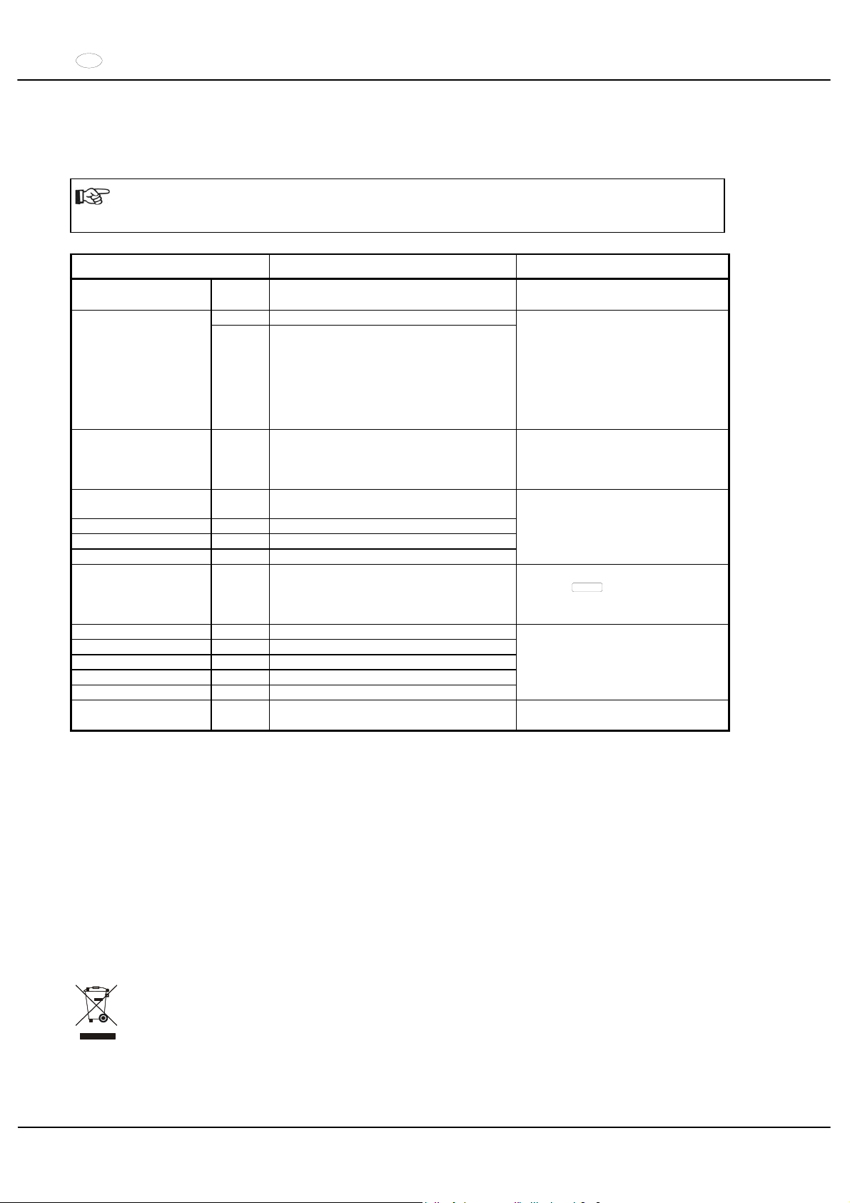
EN
36/104
27 Faults
If the fault cannot be eliminated with the help of the fault table, please inform Customer Service.
Please state the type of centrifuge and the factory serial number. Both values are visible on the centrifuge type plate.
Perform a MAINS RESET:
Switch off the mains switch (switch position "0").
Wait at least 10 seconds and then switch on the mains switch again (switch position ",").
Message / fault Cause Remedy
No display --- No voltage.
Overvoltage protection tripped out.
Check supply voltage.
Mains switch ON.
01 Faulty speedometer. TACHO - ERROR
02 No rotor installed.
Defective motor, frequency converter or
drive.
Open the cover.
Switch off the mains switch
(switch position "0").
Wait at least 10 seconds.
Turn the rotor vigorously by hand.
Switch on the mains switch again
(switch position ","). The rotor
must turn during switch-on.
IMBALANCE --- The rotor is unevenly loaded.
Open lid.
Check the loading of the rotor,
see chapter "Loading the rotor".
Repeat the centrifugation run.
CONTROL - ERROR 04,
06 - 09
Error in lid locking or lid closure.
N > MAX 05 Rotation too fast
N < MIN 13 Rotation too slow
ROTORCODE 10 Incorrect rotor coding
Perform a MAINS RESET.
MAINS INTERRUPT --- Power failure during the centrifugation run.
(The centrifugation run was not finished.)
Open lid.
Push
START
button.
Repeat the centrifugation run if
necessary.
VERSIONS-ERROR 12 Mismatch between electronic components
CONTROL-ERROR 21 - 27 Error / defective control unit
SER I/O - ERROR 30 - 38 Error / defective interface
° C * - ERROR 50 - 56 Error / defective cooling
FU / CCI - ERROR 60 - 83 Error / defective motor control
Perform a MAINS RESET.
N ! ROTOR MAX
--- Speed in the selected program greater than
the maximum speed of the rotor.
Check the set speed.
Reduce the set speed
28 Acceptance of the centrifuges for repair
If the centrifuge is returned to the manufacturer for repair, it must be decontaminated and cleaned to protect persons,
environment and material.
We reserve the right to accept contaminated centrifuges.
Costs incurred for cleaning and disinfection are to be charged to the customer.
We ask for your understanding in this matter.
29 Disposal
When you are disposing of the device, the respective statutory rules must be observed.
Pursuant to guideline 2002/96/EC (WEEE), all devices supplied after August 13, 2005 may not be disposed as part of
domestic waste. The device belongs to group 8 (medical devices) and is categorized in the business-to-business
field.
The icon of the crossed-out trash can shows that the device may not be disposed as part of domestic
waste.
The waste disposal guidelines of the individual EC countries might vary. If necessary, contact your
supplier.
Page 37

FR
37/104
Table des matières
1 Usage conforme ...................................................................................................................................................39
2 Risques résiduels .................................................................................................................................................39
3 Données techniques .............................................................................................................................................39
4 Consignes de sécurité ..........................................................................................................................................41
5 Signification des symboles....................................................................................................................................42
6 Composition de la livraison...................................................................................................................................42
7 Déballer la centrifugeuse ......................................................................................................................................42
8 Mise en service.....................................................................................................................................................43
9 Ouvrir et fermer le couvercle.................................................................................................................................43
9.1 Ouvrir le couvercle.........................................................................................................................................43
9.2 Fermer le couvercle.......................................................................................................................................43
10 Montage et démontage du rotor ........................................................................................................................44
11 Chargement du rotor .........................................................................................................................................44
12 Fermer le rotor à orientation libre de manière étanche aux aérosols ................................................................44
13 Organes de commande et indicateurs...............................................................................................................44
13.1 Icônes de la console de commande...........................................................................................................44
13.2 Touches de la console de commande........................................................................................................45
13.3 Possibilités de réglage ...............................................................................................................................45
14 Saisie des paramètres de centrifugation ...........................................................................................................46
15 Programmation..................................................................................................................................................46
15.1 Saisie / Modification de programme...........................................................................................................46
15.2 Appel de programme..................................................................................................................................46
16 Centrifugation....................................................................................................................................................46
16.1 Centrifugation avec sélection de temps préalable......................................................................................47
16.2 Centrifugation continue ..............................................................................................................................47
16.3 Centrifugation rapide..................................................................................................................................47
17 Arrêt d'urgence..................................................................................................................................................47
18 Signal sonore ....................................................................................................................................................47
19 Interrogation du compteur de durée de fonctionnement....................................................................................47
20 Refroidissement (uniquement sur centrifugeuse avec refroidissement)............................................................48
20.1 Refroidissement en veilleuse .....................................................................................................................48
20.2 Pré-refroidissement du rotor ......................................................................................................................48
21 Chauffage (uniquement sur centrifugeuse avec l'option Chauffer/refroidir).......................................................48
22 Accélération centrifuge relative (RCF)...............................................................................................................48
23 Centrifugation de substances à haute densité...................................................................................................48
24 Identification de rotor.........................................................................................................................................49
25 Déverrouillage d'urgence...................................................................................................................................49
26 Entretien et maintenance ..................................................................................................................................49
26.1 Centrifugeuse.............................................................................................................................................49
26.2 Rotors et accessoires.................................................................................................................................50
26.2.1 Goupilles de fixation............................................................................................................................50
26.2.2 Rotors et accessoires ayant une durée d'utilisation limitée.................................................................50
26.3 Autoclavage ...............................................................................................................................................50
Page 38

FR
38/104
26.4 Réservoirs de centrifugation ...................................................................................................................... 50
27 Défauts..............................................................................................................................................................51
28 Réparation des centrifugeuses..........................................................................................................................52
29 Élimination des déchets ....................................................................................................................................52
30 Anhang / Appendix............................................................................................................................................69
30.1 Rotoren und Zubehör / Rotors and accessories......................................................................................... 69
Page 39
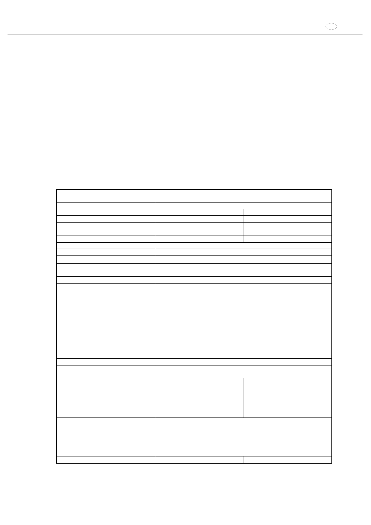
FR
39/104
1 Usage conforme
La présente machine correspond à un produit de médecine (centrifugeuse de laboratoire) au sens de la directive IVD
98/79/EG. La centrifugeuse sert à séparer les substances ou les substances mélangées ayant une densité
supérieure à 1,2 kg/dm³ au max. Cela concerne également les substances et les substances mélangées d'origine
humaine. La centrifugeuse est uniquement destinée à cette utilisation. Tout usage autre ou dépassant ce contexte
est considéré comme non-conforme. La société Andreas Hettich GmbH & Co. KG décline toute responsabilités pour
les dégâts causés par un usage non-conforme.
L’usage conforme comprend également le respect des instructions du mode d’emploi et l’exécution des travaux
d’inspection et de maintenance.
2 Risques résiduels
La machine est construite selon l’état de la technique et les règles de sécurité technique reconnues. Une utilisation et
un maniement incorrect peuvent entraîner des risques de blessure et de décès pour l'utilisateur ou les tiers ou bien
provoquer des dommages sur la machine ou les autres biens matériels. La machine doit uniquement être utilisée
dans le cadre de son usage conforme et dans un état de sécurité technique irréprochable.
Il convient de dépanner immédiatement tout dérangement susceptible d’affecter la sécurité.
3 Données techniques
Fabricant
Andreas Hettich GmbH & Co. KG
D-78532 Tuttlingen
Modèle ROTANTA 460
Type 5600 5600-01
Tension du réseau (r 10%) 208-240 V 1a
110-127 V 1~
Fréquence du réseau 50 - 60 Hz 50 - 60 Hz
Charge de connexion 1500 VA 1300 VA
Consommation de courant 6.5 A 11 A
Réfrigérant ---Capacité max. 4 x 750 ml
Densité admise
1.2 kg/dm
3
Vitesse de rotation (RPM) 15000
Accélération (RCF) 24400
Energie cinétique 41000 Nm
Obligation de contrôle (BGR 261) oui
Conditions ambiantes (EN 61010-1)
Emplacement
uniquement dans les intérieurs
Hauteur
Jusqu’à 2000 m au dessus du niveau de la mer
Température ambiante
2°C à 40°C
Humidité de l’air
humidité de l’air max. relative 80% pour températures jusqu’à 31°C,
décroissant en linéaire jusqu’à 50% de l’humidité relative pour 40°C.
Catégorie de surtension
(IEC 60364-4-443)
,,
Degré d’encrassement
2
Catégorie de protection de l’appareil
,
Non approprié pour l’usage dans un environnement exposé aux
explosions.
EMV
Emission de parasites
(antiparasitage)
EN 55011,
Groupe 1, catégorie B
EN 61000-3-3
FCC Class A
Résistance aux interférences
EN 61000-6-1 ----
Niveau du bruit (en fonction du rotor)
d 67 dB(A)
Dimensions
Largeur
554 mm
Profondeur
707 mm
Hauteur
453 mm
Poids 106 kg 115 kg
Page 40
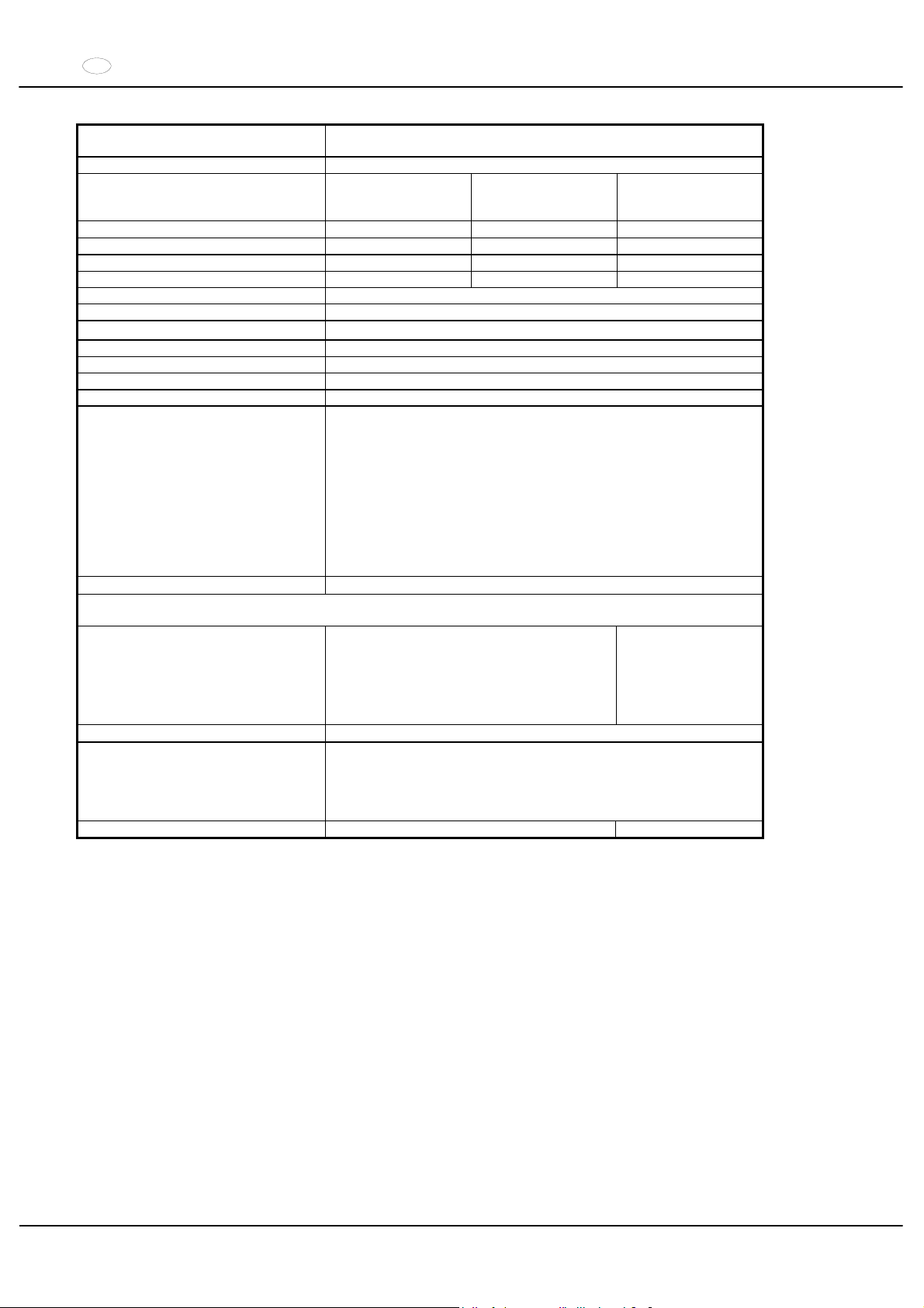
FR
40/104
Fabricant
Andreas Hettich GmbH & Co. KG
D-78532 Tuttlingen
Modèle ROTANTA 460 R
Type
5605,
5605-20
5605-50
5605-07
5605-01,
5605-51
Tension du réseau (r 10%) 208-240 V 1a
208-240 V 1~ 110-127 V 1~
Fréquence du réseau 50 - 60 Hz 60 Hz 60 Hz
Charge de connexion 2400 VA 2200 VA 2000 VA
Consommation de courant 10 A 10 A 16 A
Réfrigérant R 404A
Capacité max. 4 x 750 ml
Densité admise
1.2 kg/dm
3
Vitesse de rotation (RPM) 15000
Accélération (RCF) 24400
Energie cinétique 51000 Nm
Obligation de contrôle (BGR 261) oui
Conditions ambiantes (EN 61010-1)
Emplacement
uniquement dans les intérieurs
Hauteur
Jusqu’à 2000 m au dessus du niveau de la mer
Température ambiante
5°C à 35°C
Humidité de l’air
humidité de l’air max. relative 80% pour températures jusqu’à 31°C,
décroissant en linéaire jusqu’à 50% de l’humidité relative pour 40°C.
Catégorie de surtension
(IEC 60364-4-443)
,,
Degré d’encrassement
2
Catégorie de protection de l’appareil
,
Non approprié pour l’usage dans un environnement exposé aux
explosions.
EMV
Emission de parasites
(antiparasitage)
EN 55011,
Groupe 1, catégorie B
EN 61000-3-3
FCC Class A
Résistance aux interférences
EN 61000-6-1 ----
Niveau du bruit (en fonction du rotor)
d 64 dB(A)
Dimensions
Largeur
770 mm
Profondeur
707 mm
Hauteur
453 mm
Poids 147 kg 156 kg
Page 41

FR
41/104
4 Consignes de sécurité
Le non respect des présentes consignes exclut tout recours à la garantie.
xIl importe de lire et de respecter le mode d’emploi avant la mise en service de la centrifugeuse.
Seules les personnes ayant lu et compris le mode d’emploi sont autorisées à manipuler l’appareil.
x
Outre le mode d’emploi et les réglementations contraignantes relatives à la prévention des accidents, il importe
également de respecter les règles spécifiques et communément admises en matière de sécurité et de travail.
Le mode d’emploi doit être complété des dispositions nationales applicables à la prévention des accidents et à la
protection de l’environnement.
xLa centrifugeuse a été construite conformément à l’état actuel de la technique et son fonctionnement est sûr.
Elle peut cependant présenter des dangers pour l’utilisateur ou des tiers si son utilisation n’est pas confiée à
un personnel dûment formé, est inadéquate ou non conforme à sa destination.
xVeiller à la stabilité de la centrifugeuse.
xAvant d’utiliser la centrifuge, il est indispensable de vérifier la fixation correcte du rotor.
xDurant un processus de centrifugation, aucune personne, matière dangereuse et aucun objet ne doivent se
trouver dans une zone de sécurité de 300 mm autour de la centrifugeuse selon IEC 61010-2-020.
xPendant le fonctionnement, la centrifugeuse ne devra pas être déplacée ou être heurtée.
xEn cas de défaillance ou en cas de déverrouillage d’urgence, ne jamais intervenir dans l’appareil lorsque le rotor
tourne.
xAfin d'éviter les dommages causés par la condensation en passant d'un local froid à un local chaud, il faut soit
réchauffer la centrifugeuse en la laissant pendant au moins 3 heures dans le local chaud avant de la raccorder au
secteur, soit la faire fonctionner pendant 30 minutes dans le local froid pour la chauffer.
xPour cet appareil, vous ne devez utiliser que des rotors et des accessoires homologués par le fabricant (voir
chapitre "Anhang/Appendix, Rotoren und Zubehör/Rotors and accessories").
xLe rotor de la centrifugeuse doit uniquement être chargé conformément au chapitre "Chargement du rotor".
xDans le cas de la centrifugation à la vitesse maximale, la densité des substances et des mélanges de substances
ne doit pas excéder 1,2 kg/dm3.
xIl est interdit de procéder à des centrifugations en présence de défauts d’équilibrage.
xLa centrifugeuse ne doit pas être exploitée dans un environnement explosif.
xIl est interdit de procéder à des centrifugations :
avec des matières inflammables ou explosives,
avec des matières susceptibles de réagir chimiquement ou de dégager d’importantes quantités d’énergie.
xEn cas de centrifugation de substances dangereuses ou de substances mixtes toxiques, radioactives ou
contaminées par des micro-organismes pathogènes, il incombe à l’utilisateur de prendre les mesures ad hoc.
Il faut systématiquement utiliser des récipients de centrifugation avec des bouchons spéciaux à vis destinés aux
substances dangereuses. Dans le cas des substances des groupes de risques 3 et 4, il faut utiliser un système
de sécurité biologique en plus des récipients de centrifugation pouvant être obturés (voir le manuel "Laboratory
Biosafety Manual" publié par l’Organisation Mondiale de la Santé).
Dans un système de sécurité biologique, un joint biologique (bague d’étanchéité) placé entre les supports et le
capot empêchera la fuite de gouttelettes et d’aérosols.
Lorsque la suspension d'un système de sécurité biologique est utilisée sans couvercle, il faut enlever la bague
d'étanchéité de la suspension pour éviter de l'endommager pendant le cycle de centrifugation. Les bagues
endommagées ne doivent plus être utilisées pour assurer l'étanchéité le système de sécurité biologique.
En l'absence d'un système de sécurité biologique, une centrifugeuse n'est pas étanche du point de vue
microbiologique au sens de la norme EN 61010-2-020.
Pour ce qui concerne les systèmes à sécurité biologique, voir le chapitre "Anhang/Appendix, Rotoren und
Zubehör/Rotors and accessories". Dans le doute vous pouvez obtenir les informations auprès du fabricant.
xIl est interdit de centrifuger des matières fortement corrosives pouvant réduire la résistance mécanique des
rotors, des supports et des accessoires.
xLes rotors, balanciers et accessoires qui présentent d'importantes traces de corrosion ou des défauts mécaniques
ou dont la durée d'utilisation a expiré ne doivent plus être utilisés.
xLes réparations ne peuvent être effectuées que par une personne autorisée à cet effet par le fabricant.
xUtiliser uniquement les pièces de rechange originales et les accessoires d'origine homologués par les
Etablissements Andreas Hettich GmbH & Co. KG.
xLes dispositions de sécurité suivantes font foi :
IEC 61010-1 et IEC 61010-2-020 ainsi que les dérogations nationales.
xLa sécurité et la fiabilité de la centrifugeuse seront uniquement garanties si :
la centrifugeuse est utilisée conformément aux instructions du mode d’emploi,
l’installation électrique du site de la centrifugeuse est conforme aux prescriptions IEC,
les contrôles prescrits selon BGV A1, BGR 261 sont effectués par un personnel spécialisé averti.
Page 42
FR
42/104
5 Signification des symboles
Symbole sur la machine:
Attention, zone de danger général.
Avant l’utilisation de la centrifuge, il est indispensable de lire le mode d’emploi et de respecter les
consignes de sécurité !
Symbole dans le mode d’emploi:
Attention, zone de danger général.
Ce symbole indique des consignes de sécurité et signale des situations pouvant être sources de danger.
Le non-respect de ces instructions peut entraîner des dégâts matériels et personnels.
Symbole sur la machine et dans le mode d'emploi:
Faire attention aux surfaces chaudes.
Symbole sur la machine et dans le mode d'emploi:
Le pendant à rainure en matière plastique, N° de commande 5091, ne peut être utilisée que pour des
températures allant jusqu’à 40°C max.
Symbole sur la machine:
Équipotentiel : connecteur à fiche (connecteur L.E.P.) pour la liaison équipotentielle (uniquement pour
une centrifugeuse avec un connecteur L.E.P.).
Symbole dans le mode d’emploi:
Ce symbole signale des informations importantes.
Symbole sur la machine et dans le mode d'emploi:
Symbole pour la collecte séparée des appareils électriques et électroniques, conformément á la directive
2002/96(EG (WEEE). L’appareil fait partie du groupe 8 (appareils de médecine).
Utilisation dans les pays de l’Union Européenne ainsi qu’en Norvège et en Suisse.
6 Composition de la livraison
1 Câble de connexion
1 Clé mâle coudée 2,5 mm
1 Clé mâle coudée 5 mm
1 Graisse pour tourillon porteur
1 Mode d’emploi
1 Fiche de consignes pour le transport
Le(s) rotor(s) et accessoires correspondant sont livrés selon les spécifications de la commande.
7 Déballer la centrifugeuse
xSoulever le carton et retirer le matériau d'amortissement.
x
Ne pas saisir sur le tableau de commande frontal pour soulever.
Tenir compte du poids de la centrifugeuse, voir au chapitre "Données techniques".
Avec un nombre suffisant d'aides, soulever la centrifugeuse sur les deux faces et la déposer sur la table de
laboratoire.
Page 43
FR
43/104
8 Mise en service
x
Aux termes de la norme EN sur les laboratoires IEC 61010-2-020, l'installation locale doit être équipée d'un
interrupteur d'arrêt d'urgence pour sectionner l'alimentation du secteur en cas de défaut.
Cet interrupteur doit être éloigné de la centrifugeuse, de préférence hors de la pièce dans laquelle est la
centrifugeuse ou près de la porte.
xPlacer la centrifugeuse sur un emplacement approprié de manière à ce qu'elle soit stable et mettre de niveau.
Lors de la mise en place, il faut respecter la zone de sécurité exigée de 300mm autour de la centrifugeuse selon
IEC 61010-2-020.
Durant un processus de centrifugation, aucune personne, matière dangereuse et aucun objet ne
doivent se trouver dans une zone de sécurité de 300 mm autour de la centrifugeuse selon
IEC 61010-2-020.
xNe pas placer d’objet devant la grille de ventilation.
Ménager un espace de ventilation de 300 mm autour de la grille.
xPour la centrifugeuse de type 5605-20, raccorder l’alimentation en azote selon la fiche de consignes jointe
AH5605-20XX.
Le raccord de la centrifugeuse doit absolument être effectué conformément à la fiche de consignes
jointe.
Observer impérativement la feuille de consignes jointe.
xCentrifugeuse avec un connecteur L.E.P. :
relier en cas de besoin le connecteur L.E.P. au dos de l'appareil à un système médical de liaison équipotentielle
supplémentaire.
xVérifier que la tension de secteur est identique à la mention de la plaque signalétique.
xRaccorder la centrifugeuse à une prise de secteur normalisée au moyen du câble de connexion. Puissance
connectée voir chapitre "Données techniques".
xActiver l'interrupteur de secteur. Amener l'interrupteur en position ",
".
Le type de la machine et la version du programme s’affichent, les diodes s’allument. Au bout de 8
secondes,
OPEN OEFFNEN s’affiche. La DEL s’allume.
xOuvrir le capot.
Les dernières données de centrifuge utilisées s’affichent.
xEnlever la sécurité de transport (voir la fiche de consignes "Sécurité de transport").
9 Ouvrir et fermer le couvercle
9.1 Ouvrir le couvercle
Le capot ne peut être ouvert que lorsque la centrifugeuse est sous tension et que le rotor est à l’arrêt. Dans
les autres cas, voir le chapitre, "Déverrouillage d’urgence".
xAppuyer sur la touche sur le panneau frontal. Le couvercle est déverrouillé par le moteur, l'éclairage de la
touche
et la DEL s'éteignent.
9.2 Fermer le couvercle
Ne pas mettre les doigts entre le couvercle et le boîtier.
Ne pas laisser tomber le couvercle pour le fermer.
xMettre le couvercle en place et appuyer légèrement sur la bordure avant du couvercle. Le verrouillage est
automatique. La touche
et la diode s'allument.
Page 44
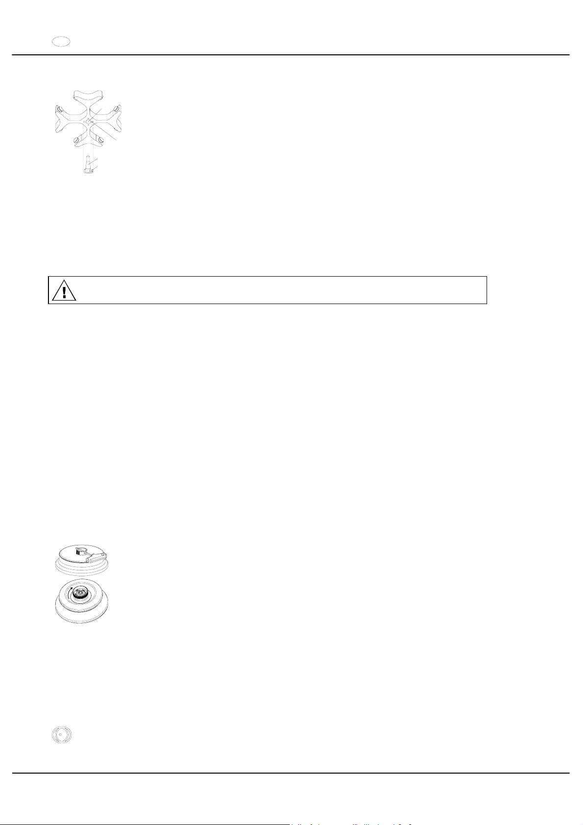
FR
44/104
10 Montage et démontage du rotor
A
B
C
D
x
Nettoyer l'arbre d'entraînement (C) et l'alésage du rotor (A) et enduire ensuite l'arbre
d'entraînement d'une pellicule de graisse. Les particules d'impuretés entre l'arbre
d'entraînement et le rotor réduisent la stabilité d'assise du rotor et provoquent un
fonctionnement irrégulier.
xEnficher le rotor à la verticale sur l'arbre d'entraînement. Le taquet de l'arbre
d'entraînement (D) doit être logé dans la rainure du rotor (B). L'orientation de la rainure
est indiquée sur le rotor.
xSerrer l'écrou de fixation du rotor avec la clé de la livraison en tournant dans le sens
horloger.
xVérifier la stabilité d'assise du rotor.
xDémontage du rotor : Desserrer l'écrou de fixation par rotation dans le sens anti-
horloger jusqu'à ce que le rotor puisse être détaché par pression. En exerçant une
légère pression, détacher le rotor du cône de l'arbre d'entraînement. Dévisser l'écrou de
fixation jusqu'à ce que le rotor soit détaché de l'arbre d'entraînement.
11 Chargement du rotor
Des récipients standard de centrifugation en verre sont résistants jusqu' à un ACR de 4000 (DIN 58970,
partie 2).
xVérifier la stabilité d'assise du rotor.
xDans le cas des rotors à balanciers, toutes les positions des rotors doivent être équipées avec les mêmes
balanciers. Certains balanciers sont désignés avec le numéro de la place du rotor. Ces balanciers doivent
exclusivement être installés dans la place de rotor correspondante.
xLe chargement des rotors et des balanciers doit être nécessairement symétrique. Pour les combinaisons
possibles, voir le Chapitre "Anhang/Appendix, Rotoren und Zubehör/Rotors and accessories".
Dans le cas des rotors à angle fixe, il faut charger tous les logements possibles du rotor, voir au chapitre
"Annexe/Appendix, Rotors et accessoires/Rotors and accessories".
xSur certains balanciers sont indiqués le poids du chargement maximal et le poids maximal du balancier
entièrement équipé. Ces poids ne doivent pas être dépassés. L’indication du poids de la charge maximale
comprend le poids total de la réduction, châssis, récipient de centrifugation et contenu.
xDans le cas des récipients à garniture de caoutchouc, les récipients de centrifugation doivent avoir le même
nombre de garnitures dans la partie inférieure.
xLes récipients de centrifugation doivent toujours être remplis hors de la centrifugeuse.
xAucun liquide ne doit parvenir dans le bol de centrifugeuse pendant le remplissage et le déplacement des
balanciers.
xLa quantité maximale de remplissage indiquée par le fabricant pour les récipients de centrifugation ne doit pas
être dépassée.
xLa hauteur de remplissage des récipients sera autant que possible égale pour maintenir les différences de poids
entre les récipients de centrifugation aussi réduites que possible .
12 Fermer le rotor à orientation libre de manière étanche aux aérosols
Afin de garantir l’étanchéité aux aérosols, le couvercle d’un rotor avec tube à orientation
libre étanche aux aérosols doit être correctement fermé.
Ceci s’effectue en insérant la clé livrée dans la fourniture dans l’orifice de la poignée
béquille. Si la poignée béquille ne possède pas d’orifice, le couvercle doit être fermé
correctement à la main en tournant la poignée dans le sens des aiguilles d’une montre.
Rotors à orientation libre disponibles, voir chapitre "Anhang/Appendix, Rotoren und
Zubehör/Rotors and accessories".
13 Organes de commande et indicateurs
Voir illustration sur la page 2.
Fig. 2, Fig. 3: Console des indicateurs et organes de commande
13.1 Icônes de la console de commande
Indicateur de déséquilibre. L'indicateur de déséquilibre s'allume lorsque la différence de poids autorisée est
dépassée pour le chargement du rotor.
Page 45
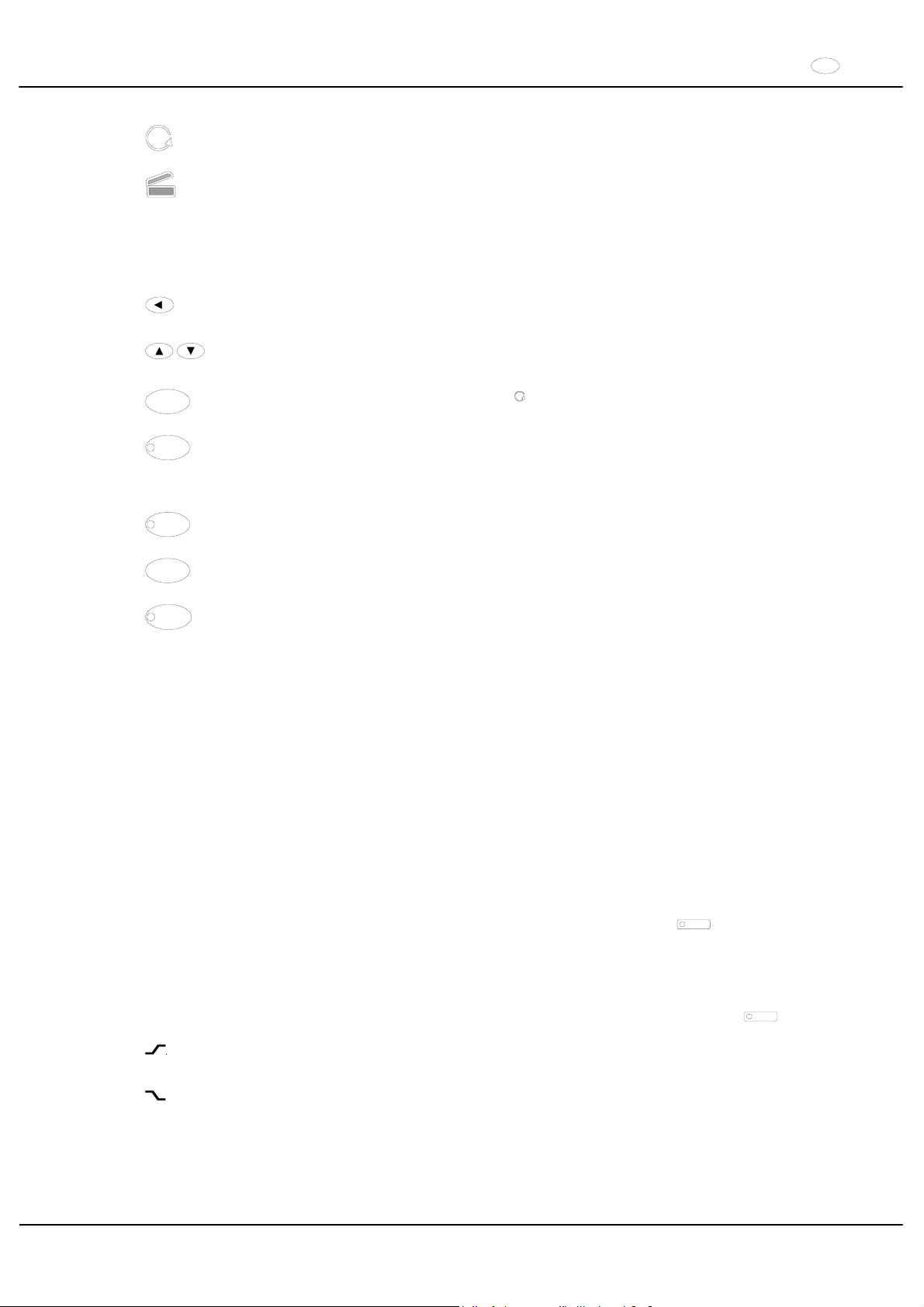
FR
45/104
Indicateur de rotation. L'indicateur de rotation s'allume pendant la centrifugation et reste allumé tant que le
rotor tourne.
Indicateur de couvercle. L'indicateur de couvercle s'allume lorsque le couvercle est fermé et verrouillé.
L'indicateur de couvercle s'éteint pendant la centrifugation.
Les erreurs de commande et les défauts sont signalés par des icônes sur l'afficheur (voir le Chapitre "Défauts").
13.2 Touches de la console de commande
Touche de sélection des différents paramètres.
Les paramètres sont sélectionnés l'un après l'autre en appuyant sur la touche.
Incrémenter/Décrémenter la valeur du paramètre sélectionné précédemment en appuyant sur les touches
fléchées. Le maintien de l'action sur la touche fléchée entraîne la modification rapide des valeurs.
START
Démarrer la centrifugation. L'indicateur de rotation s'allume.
Transfert des entrées et modifications.
STOP
Stopper la centrifugation.
Le rotor est décéléré à la vitesse de freinage sélectionnée. La diode luminescente incorporée dans la
touche reste allumée jusqu'à ce que le rotor soit immobilisé. L'ARRET D'URGENCE est activé en appuyant
deux fois sur la touche.
RCF
Sélection de l'indicateur RCF.
La diode luminescente incorporée dans la touche s'allume.
IMPULS
Centrifugation rapide.
La centrifugation est exécutée tant que l'action est maintenue sur la touche.
PROG
Sauvegarde et appel de programmes.
Les programmes sont sélectionnés dans l'ordre l'un après l'autre en appuyant sur la touche (1 - 2 - 3 - #).
13.3 Possibilités de réglage
t/min Réglage de 1 à 99 min, par in incréments de 1 min.
t/sec Réglage de 1 à 59 s, par incréments de 1 seconde.
Fonctionnement continu "
f".
RPM Vitesse. Il est possible de régler une valeur numérique comprise entre 500 RPM et la vitesse de rotation
maximale du rotor. Pour la vitesse maximale de rotation du rotor, se reporter au chapitre
"Anhang/Appendix, Rotoren und Zubehör/Rotors and accessories“. Paramétrable de 500 RPM à 10000
RPM par intervalles de 10 et à partir de 10000 RPM jusqu'à la vitesse maximale de rotation, par intervalles
de 100.
RAD/mm Rayon de centrifugation. Valeurs en mm. Pour la saisie de rayon de centrifugation, voir le Chapitre
"Anhang/Appendix, Rotoren und Zubehör/Rotors and accessories". La saisie du rayon n'est possible que
lorsque l'indicateur RCF a été sélectionné (la diode incorporée dans la touche
RCF
s'allume).
RCF Accélération relative de centrifugation. Il est possible de régler une valeur numérique dont découle une
vitesse de rotation située entre 500 RPM et la vitesse maximale de rotation du rotor. Réglage par
incréments de 1 jusqu'à 100, par incréments de 10 à partir de 100. La valeur RCF est arrondie
automatiquement au chiffre supérieur/inférieur en fonction de l'incrément de vitesse. La saisie de RCF n'est
possible que lorsque l'indicateur RCF est sélectionné (la diode incorporée dans la touche
RCF
s'allume).
Etages de montée en puissance de 1 à 9. Etage 9 = temps de montée en puissance le plus court, étage 1 =
temps de montée en puissance le plus long.
Etages de décélération de 0 à 9. Etage 9 = temps de décélération le plus court, étage 1 = étage de
décélération long,
étage 0 = étage de décélération le plus long (décélération par inertie, sans freinage).
Page 46
FR
46/104
T/°C Valeur de température de consigne (uniquement sur centrifugeuse avec refroidissement). Réglage de
-20 °C à +40 °C, par incréments de 1 °C (réglable de -20°C à +60°C / +90°C avec l'option
Chauffer/refroidir). La température la plus basse pouvant être établie est fonction du rotor (voir le Chapitre
"Anhang/Appendix, Rotoren und Zubehör/Rotors and accessories").
PROG Numéro de programme. Il est possible cde sauvegarder 3 programmes (positions de programme 1 - 2 - 3).
La position de programme # sert de mémoire temporaire pour la modification des réglages.
14 Saisie des paramètres de centrifugation
Après sélection de paramètres et pendant la sélection des paramètres, l'indicateur bascule sur les valeurs
précédentes si aucune action n'exécutée sur les touches pendant 8 secondes. Il est alors nécessaire de
recommencer la saisie des paramètres.
xSélectionner l'indicateur RPM ou RCF en appuyant sur la touche
RCF
La diode incorporée dans la touche
RCF
s'allume après sélection de l'indicateur RCF.
xSélectionner les paramètres souhaités en appuyant sur la touche
et ajuster en appuyant sur les touches
.
Afin de régler le fonctionnement continu, il faut mettre les paramètres
t/min et t/sec à zéro avec la touche
. Le
fonctionnement continu est indiqué dans l'affichage par le symbole "f
".
xAprès entrée de tous les paramètres, appuyer sur la touche
START
pour sauvegarder les réglages sur la position
de programme #. La saisie est confirmée par affichage de
ok pendant un instant.
Les données de la position de programme # sont écrasées par entrée de paramètres et en appuyant sur la
touche
START
.
15 Programmation
15.1 Saisie / Modification de programme
xSélectionner l'indicateur RPM ou RCF en appuyant sur la touche
RCF
. la diode incorporée dans la touche
RCF
. s'allume après sélection de RCF.
xSélectionner les paramètres souhaités en appuyant sur la touche et ajuster en appuyant sur les touches
xSélectionner le paramètre PROG en appuyant sur la touche et régler la position de programme souhaitée en
appuyant sur les touches
La diode incorporée dans la touche
PROG
s'allume.
xAppuyer sur la touche
PROG
pour sauvegarder les réglages sur la position de programme souhaitée. La saisie
est confirmée par affichage de
ok pendant un instant.
15.2 Appel de programme
x
Sélectionner la position de programme souhaitée en appuyant sur la touche
PROG
.
Les informations de centrifugation de la position de programme sélectionné sont affichées.
xVérifier les paramètres en appuyant sur la touche
.
16 Centrifugation
Durant un processus de centrifugation, aucune personne, matière dangereuse et aucun objet ne doivent se
trouver dans une zone de sécurité de 300 mm autour de la centrifugeuse selon IEC 61010-2-020.
L'entraînement est stoppé en phase de montée en puissance si la différence de tare admissible a été
dépassée pendant le chargement du rotor, l'indicateur de déséquilibre s'allume et la mention
IMBALANCE est
affichée.
Si la vitesse de rotation du programme sélectionné est supérieure à la vitesse de rotation maximale du rotor,
aucun processus de centrifugation ne peut être lancé. La mention
N > ROTOR MAX est affichée (voir le
Chapitre "Défauts").
La centrifugation peut être stoppée n'importe quand en appuyant sur la touche
STOP
.
Il est possible de sélectionner et de modifier tous les paramètres pendant la centrifugation (voir le Chapitre
"Saisie des paramètres de centrifugation").
Il est possible de basculer n'importe quand sur l'indicateur RPM et RCF en appuyant sur la touche
RCF
.
Pour travailler avec l'indicateur RCF, il est nécessaire d'entrer le brayon de centrifugation.
Après affichage de
OPEN OEFFNEN (= OUVRIR) la commande de centrifugeuse n'est possible qu'après
avoir ouvert le couvercle une fois.
Si
R xx n-max xxxxx est affiché, la marche de centrifugation n’a pas été exécutée en raison du changement
du rotor, voir chapitre "Identification de rotor".
Page 47

FR
47/104
xMettre la centrifugeuse sous tension. Amener l'interrupteur en position ,.
xCharger le rotor et fermer le couvercle de centrifugeuse.
16.1 Centrifugation avec sélection de temps préalable
x
Régler le temps et appeler un programme avec sélection de temps préalable (voir le Chapitre "Saisie des
paramètres de centrifugation" ou "Appel de programme").
xAppuyer sur la touche
START
L'indicateur de rotation reste allumé pendant toute la durée de fonctionnement
du rotor.
xLa décélération selon l'étage de freinage sélectionné est exécutée après écoulement du temps ou interruption de
la centrifugation en appuyant sur la touche
STOP
. L'étage de freinage est affiché.
Pendant la centrifugation, l'afficheur donne la vitesse du rotor ou la valeur RCF résultants, la température des
échantillons (uniquement sur centrifugeuse avec refroidissement) et la durée restante.
16.2 Centrifugation continue
xAjuster sur l'icône f ou appeler un programme de centrifugation continue (voir le Chapitre "Saisie des
paramètres de centrifugation" ou "Appel de programme").
xAppuyer sur la touche
START
. L'indicateur de rotation reste allumé pendant toute la durée de fonctionnement
du rotor. Le compte du temps commence à 00:00.
xPour stopper la centrifugation, appuyer sur la touche
STOP
. La décélération est exécutée selon l'étage de
freinage sélectionné. L'étage de freinage est affiché.
Pendant la centrifugation, l'afficheur donne la vitesse du rotor ou la valeur RCF résultants, la température des
échantillons (uniquement sur centrifugeuse avec refroidissement) et la durée restante.
16.3 Centrifugation rapide
xAppuyer sur la touche
IMPULS
et maintenir l'action. L'indicateur de rotation reste allumé pendant toute la durée
de fonctionnement du rotor.
xPour stopper la centrifugation rapide, cesser l'action sur la touche
IMPULS
La décélération est exécutée selon
l'étage de freinage sélectionné. L'étage de freinage est affiché.
Pendant la centrifugation, l'afficheur donne la vitesse du rotor ou la valeur RCF résultants, la température des
échantillons (uniquement sur centrifugeuse avec refroidissement) et la durée restante.
17 Arrêt d'urgence
x
Appuyer 2 fois sur la touche
STOP
La décélération est exécutée sur l'étage 9 (temps de décélération le plus court) en cas d'arrêt d'urgence L'étage de
freinage 9 est affiché.
Si l'étage de freinage 0 a été sélectionné, la décélération est plus longue, pour des raisons technique, que pour
l'étage de freinage 9.
18 Signal sonore
Le signal sonore retentit :
xen présence d'un défaut à un intervalle de 2 s.
xau terme de la centrifugation et après immobilisation du rotor, à un intervalle de 30 s.
Le signal sonore cesse après ouverture du couvercle, en appuyant sur une touche quelconque.
Pour activer / désactiver le signal sonore après la centrifugation, alors que le rotor est immobilisé, procéder comme
suit :
xAppuyer sur la touche
pendant 8 s.
Après 8 s, la mention
SOUND / BELL est affichée.
xEn appuyant sur la touche
ou OFF (arrêt) ou ON (marche) selon le réglage de votre choix.
xAppuyer sur la touche
START
pour sauvegarder le réglage.
La saisie est confirmée par affichage de
ok pendant un instant.
19 Interrogation du compteur de durée de fonctionnement
Il n'est possible d'interroger le compteur de durée de fonctionnement qu'à l'arrêt du rotor.
xAppuyer sur la touche pendant 8 s.
Après 8 s, la mention
SOUND / BELL est affichée.
xAppuyer une nouvelle fois sur la touche
La durée de fonctionnement (CONTROL: ) de la centrifugeuse est affichée.
xPour quitter l'interrogation du compteur de durée de fonctionnement, appuyer sur la touche
ou
Page 48
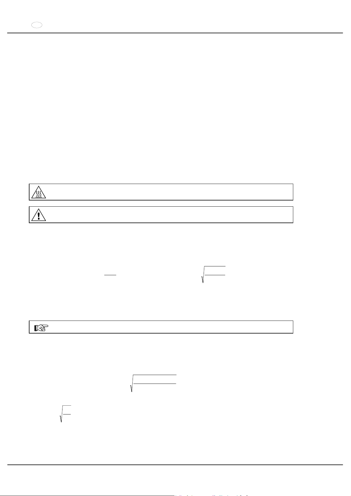
FR
48/104
20 Refroidissement (uniquement sur centrifugeuse avec refroidissement)
La température de consigne peut être réglée sur une plage de -20 °C à +40 °C. Pour les centrifugeuses équipée de
l'option Chauffer/refroidir, la valeur prescrite de la température est réglable de -20°C à +60°C / +90°C. Le minimum
de température possible est fonction du rotor (voir le Chapitre "Anhang/Appendix, Rotoren und Zubehör/Rotors and
accessories").
20.1 Refroidissement en veilleuse
A l'arrêt du rotor et lorsque le couvercle est fermé, le bol de centrifugeuse est refroidi à la température sélectionnée.
La température de consigne est indiquée sur l'afficheur.
20.2 Pré-refroidissement du rotor
Afin de garantir une préréfrigération rapide du rotor à l'état non chargé et des accessoires utilisés, il est recommandé
de sélectionner un processus de centrifugation avec les paramétrages du fonctionnement en continu et une vitesse
de rotation d'environ 20% de la vitesse de rotation maximale du rotor.
21 Chauffage (uniquement sur centrifugeuse avec l'option Chauffer/refroidir)
Au cours du fonctionnement de centrifugation, en cas de besoin, la zone de centrifugation peut être chauffée à une
température pré-sélectionnée.
Lorsque le rotor est au point mort, le chauffage est éteint.
Risque de brûlure ! La température de surface de l'élément chauffant dans le compartiment de
centrifugation de la centrifugeuse peut monter jusqu'à 500 °C / 932 °F. Ne pas toucher l'élément chauffant.
Le pendant à rainure en matière plastique, N° de commande 5091, ne peut être utilisée que pour des
températures allant jusqu’à 40°C max.
22 Accélération centrifuge relative (RCF)
L'accélération centrifuge relative (RCF) est indiqué en tant que multiple de l'accélération gravitationnelle (g). Il s'agit
d'une valeur dépourvue d'unité, qui sert à la comparaison entre la puissance de séparation et de sédimentation.
Le calcul s’effectue à l’aide de la formule suivante:
1,118r
2
1000
RPM
RCF
uu
¸
¹
·
¨
©
§
1000
1,118r
RCF
RPM
u
u
RCF = accélération centrifuge relative
RPM = régime
r = rayon de centrifugation en mm = distance qui sépare le centre de l'axe de rotation du fond de la cuve de
centrifugation. Rayon de centrifugation voir chapitre
"Anhang/Appendix, Rotoren und Zubehör/Rotors and accessories ".
L'accélération centrifuge relative (RCF) est dépendante du régime et du rayon de centrifugation.
23 Centrifugation de substances à haute densité
Les rotors sont conçus pour centrifuger à vitesse de rotation nominale des matières à densité homogène moyenne
maximale de 1,2 kg/dm3. Les matières à densités plus élevées doivent être centrifugées à vitesse plus lente.
La vitesse de rotation autorisée se calcule de la manière suivante:
nominalerotationde x Vitesse
supérieuredensité
1,2
=)(nlentetioncentrifugadeVitesse red
Exemple: RPM 4000, densité 1,6 kg/dm
3
RPM3464=4000 x
1,6
1,2
=n
red
En cas d’incertitude, prendre contact avec le fabricant.
Page 49
FR
49/104
24 Identification de rotor
Après démarrage de chaque cycle de centrifugation, la machine exécute une routine d'identification du rotor utilisé.
Après un changement de rotor, l’entraînement s’éteint et le code du rotor (R xx) ainsi que la vitesse de rotation
maximale (n-max=xxxxx) du rotor sont affichés.
Toute commande ultérieure de la centrifuge n’est possible qu’après une ouverture du couvercle.
Suite à un changement de rotor, si la vitesse maximale de rotation du rotor est inférieure à la vitesse de
rotation paramétrée, la vitesse de rotation est limitée à la vitesse maximale de rotation du rotor.
25 Déverrouillage d'urgence
En cas de panne de courant, le couvercle ne peut pas être déverrouillé avec le moteur. Il est nécessaire d'exécuter
un déverrouillage manuel.
Avant d'exécuter le déverrouillage manuel, retirer la fiche de l'alimentation.
Attendre que le rotor est à l'arrêt pour ouvrir le couvercle.
Voir illustration sur la page 2.
xCouper l'interrupteur de secteur (position de l'interrupteur "0").
xRegarder par la fenêtre située sur le couvercle pour s'assurer que le rotor est immobile.
xInsérer horizontalement la clé mâle coudée à six pans creux dans l’orifice (Fig. 1, A) et tourner avec précaution
d’un demi-tour dans le sens des aiguilles d’une montre jusqu’à ce que le couvercle puisse être ouvert.
xRetirer la clé à six pans hors de l'alésage.
xAprès avoir remis la centrifugeuse sous tension, appuyer sur la touche
pour ramener le verrouillage de
couvercle automatique en position initiale (ouvert).
26 Entretien et maintenance
Retirer la prise de secteur avant de nettoyer.
Avant d'utiliser une procédure de nettoyage ou de décontamination autre que celle recommandée par le
fabricant, l'utilisateur vérifiera auprès du fabricant que la procédure prévue n'endommage pas l'appareil.
xUtiliser des agents de nettoyage et de désinfection de pH entre 5 et 8. Ne pas utiliser les agents de nettoyage
alcalins d'un pH > 8.
xRespecter impérativement les consignes spéciales d'utilisation données par le fabricant des agents de nettoyage
et de désinfection, afin de prévenir la corrosion par les agents de nettoyage et de désinfection.
26.1 Centrifugeuse
x
Nettoyer régulièrement le boîtier de la centrifugeuse et le compartiment de centrifugation et les laver en cas de
besoin avec du savon ou un détergent doux et un chiffon humide. Ces opérations sont nécessaires pour garantir
l'hygiène et pour prévenir la corrosion par la présence durable d'impuretés.
xSécher le bol avec un chiffon absorbant en cas de dépôt d'eau de condensation dans le bol de la centrifugeuse.
xLe bol de la centrifugeuse doit être nettoyé immédiatement dans le cas où un matériau infectieux a pénétré dans
le bol de la centrifugeuse. Pour désinfecter des surfaces, nous recommandons Bacillol® Plus de la société Bode
Chemie de Hambourg ou Biocidal ZFTM de la société WAK-Chemie Medical GmbH de Steinbach.
xEnduire d'un film de graisse le joint en caoutchouc du bol de centrifugeuse au terme de chaque nettoyage.
Page 50
FR
50/104
26.2 Rotors et accessoires
x
Afin de prévenir la corrosion et les modifications des matériaux, il faut laver régulièrement les rotors et les
accessoires avec du savon ou un détergent doux et un chiffon humide. Exécuter le nettoyage au moins une fois
par semaine, l'idéal étant de nettoyer après chaque utilisation.
xUn nettoyage approprié sera exécuté dans le cas où le rotor et les accessoires ont été contaminés par un
matériau pathogène ou radioactif. Nous recommandons de procéder à la désinfection avec Helipur® H plus N de
la société B. Braun Melsungen. Pour éliminer les matières radioactives, nous recommandons decon neutracon
®
de la société Decon Laboratories Limited.
xSécher les rotors et les accessoires immédiatement après le nettoyage.
xAprès séchage, les rotors d'angle, les réservoirs et la suspension en aluminium seront enduits d'une pellicule de
graisse sans acide, par exemple la vaseline.
xVérifier régulièrement les bagues d'étanchéité (une fois par semaine) sur les rotors étanches aux aérosols et les
systèmes de sécurité biologiques (voir le chapitre "Anhang/Appendix, Rotoren und Zubehör/Rotors and
accessories"). Changer immédiatement la bague d'étanchéité si elle présente des marques de fissuration, de
friabilité et d'usure. Pour éviter une déformation de l’anneau d’étanchéité au cours de l’ouverture et de la
fermeture du couvercle, l’anneau doit être légèrement graissé avec de la graisse sans acide, par ex. Vaseline.
xDéposer le rotor au moins une fois par mois, nettoyer et enduire l'arbre d'entraînement d'une pellicule de graisse
pour prévenir la corrosion par la présente d'humidité entre le rotor et l'arbre d'entraînement.
xVérifier une fois par mois que les rotors et les accessoires ne sont pas endommagés par la corrosion.
Les rotors et les accessoires usés et endommagés par la corrosion ne doivent plus être utilisés.
xVérifier chaque semaine la stabilité de fixation du rotor.
26.2.1 Goupilles de fixation
Les goupilles de fixation des rotors à amortissement doivent être graissées régulièrement (graisse de lubrification
Hettich n° 4051) de manière à assurer le balancement régulier de la suspension.
26.2.2 Rotors et accessoires ayant une durée d'utilisation limitée
L'utilisation de certains rotors, balanciers et accessoires est limitée dans le temps.
Ceux-ci sont marqués avec une date d'expiration, par ex. : "einsetzbar bis Ende: / usable until end of:
,V. Quartal 2011" (utilisable jusqu'à la fin du 4
e
trimestre 2011).
Les rotors, balanciers et accessoires ne doivent plus être utilisés pour des raisons de sécurité, lorsque la
date d'expiration qui est marquée dessus a été atteinte.
26.3 Autoclavage
Les rotors à oscillation, les rotors angulaires en aluminium, les balanciers en métal, les couvercles avec un joint
d'étanchéité biologique, ainsi que les châssis et les réducteurs peuvent être autoclavés à 121 °C / 250 °F (20 min).
En cas de doute, il faut se renseigner auprès du fabricant.
Avant l'autoclavage, déposer le couvercle des rotors et du récipient.
L'autoclavage provoque l'accélération du vieillissement des plastiques et peut provoquer des décolorations
des plastiques.
Après le passage à l’autoclave, nous recommandons de remplacer les anneaux d’étanchéité des rotors
étanches aux aérosols et aux systèmes de sécurité bio.
26.4 Réservoirs de centrifugation
xEn cas de fuite ou de rupture de récipients de centrifugation, il faut éliminer tous les morceaux de récipients
cassés, les fragments de verre et les substances centrifugées écoulées.
xLes amortisseurs antivibrations ainsi que les caoutchouc intermédiaires des rotors doivent être remplacés après
un bris de verre.
Les fragments de verre restants peuvent entraîner d’autres bris de verre !
xS'il s'agit d'un matériau infectieux, exécuter immédiatement une désinfection.
Page 51
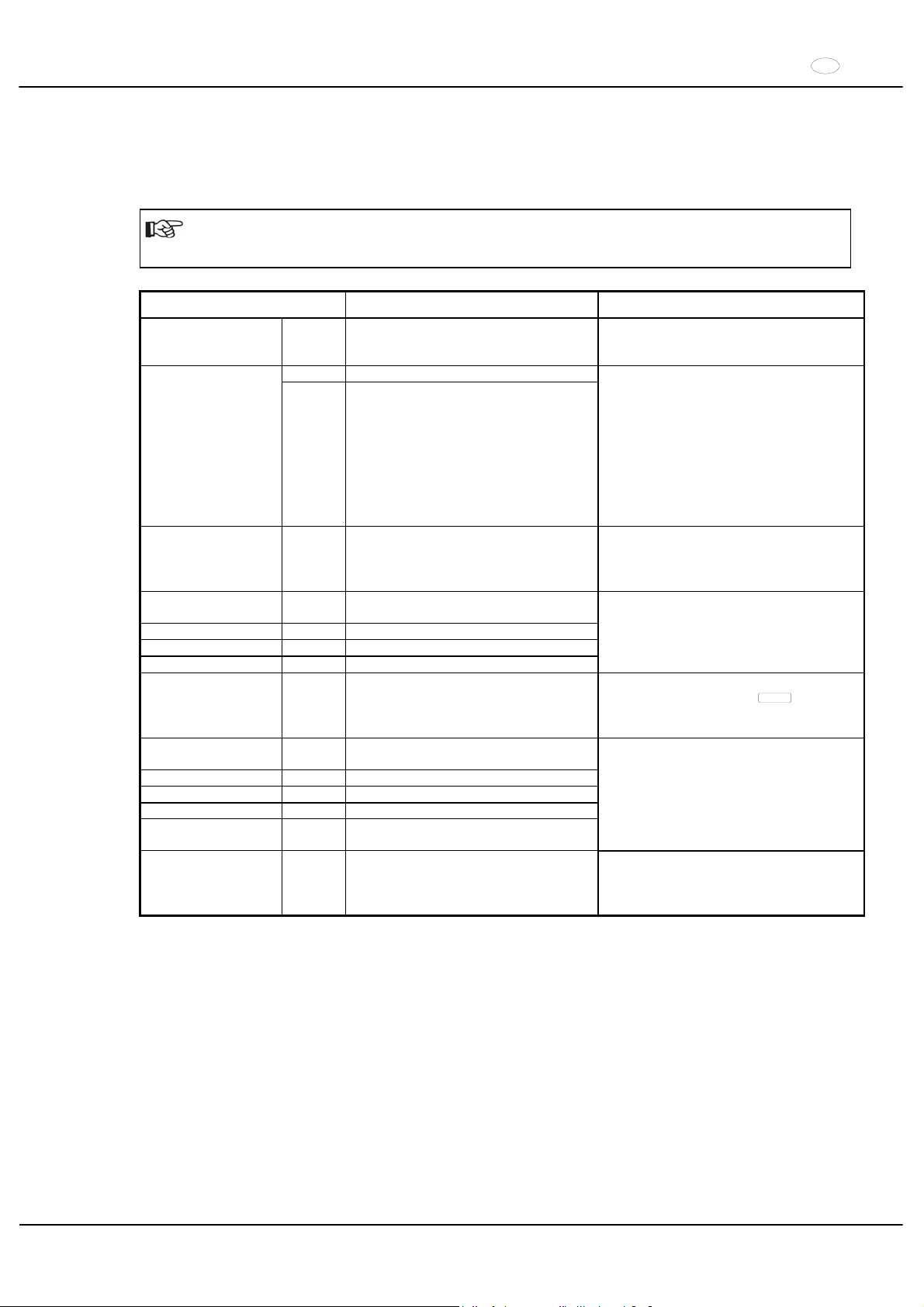
FR
51/104
27 Défauts
Si l'erreur ne peut pas être éliminée d'après le tableau des dérangements, il faut alors avertir le service après-vente.
Vous aurez l'obligeance de mentionner le modèle de centrifugeuse et le numéro d'usine. Les deux sont marqués sur
la plaque signalétique de la centrifugeuse.
Effectuer une RÉINITIALISATION DU SECTEUR :
Couper l'interrupteur de secteur (position de l'interrupteur "0").
Attendre au moins 10 secondes et refermer ensuite l'interrupteur de secteur (position de l'interrupteur ",").
Message / Erreur Origine Solution
Pas de message --- Pas de tension
Déclenchement du fusible protecteur
contre surintensité
Contrôler la tension d'alimentation
Secteur en marche
TACHO - ERROR 01 Tachymètre défectueux.
02 Absence de rotor.
Moteur, convertisseur, entraînement
défectueux.
Ouvrir le couvercle.
Couper l'interrupteur de secteur
(position de l'interrupteur "0").
Attendre au moins 10 secondes.
Tourner vigoureusement le rotor à la
main.
Refermer l'interrupteur de secteur
(position de l'interrupteur ","). Le rotor
doit fonctionner pendant la mise en
marche.
IMBALANCE --- Le rotor est chargé de manière non
symétrique.
Ouvrir le capot.
Vérifier le chargement du rotor, voir au
chapitre "Chargement du rotor".
Répéter le cycle de centrifugation.
CONTROL - ERROR 04,
06 - 09
Erreur du verrouillage ou de la fermeture
du capot.
N > MAX 05 Survitesse
N < MIN 13 Vitesse trop basse
ROTORCODE 10 Erreur codage du rotor
Effectuer une RÉINITIALISATION DU
SECTEUR.
MAINS INTERRUPT --- Interruption du secteur pendant le cycle
de centrifugation. (Le cycle de
centrifugation n'est pas terminé.)
Ouvrir le capot.
Appuyer sur la touche
START
.
En cas de besoin, répéter le cycle de
centrifugation.
VERSIONS-ERROR 12 Pas de correspondance entre les
composants électroniques
CONTROL-ERROR 21 - 27 Erreur / défectuosité de la commande
SER I/O - ERROR 30 - 38 Erreur / défectuosité de l’interface
° C * - ERROR 50 - 56 Erreur / défectuosité du refroidissement
FU / CCI - ERROR 60 – 83 Erreur / défectuosité de la commande du
moteur
Effectuer une RÉINITIALISATION DU
SECTEUR.
N > ROTOR MAX --- Vitesse de rotation paramétrée dans le
programme sélectionné supérieure à la
vitesse maximale de rotation du rotor.
Vérifier la vitesse du programme
sélectionnée
Corriger la vitesse du programme
sélectionnée
Page 52

FR
52/104
28 Réparation des centrifugeuses
Dans le cas où la centrifugeuse est expédiée au fabricant pour réparation, elle doit être décontaminée et nettoyée
avant expédition, dans le but d'assurer la protection des personnes, de l'environnement et du matériel.
Nous nous réservons le droit de refuser les centrifugeuses contaminées.
Nous facturons au client les frais de nettoyage et de désinfection.
Vous voudrez bien manifester votre compréhension pour cette réglementation.
29 Élimination des déchets
Les dispositions légales en vigueur doivent être respectées lors de l'élimination de l'appareil.
Conformément à la directive 2002/96/CE (WEEE), tous les appareils livrés après le 13.08.2005 ne doivent plus être
jetés avec les déchets ménagers. L'appareil fait partie du groupe 8 (dispositifs médicaux) et est classé dans le
domaine "Business-to-Business".
Le symbole de la poubelle barrée d'une croix indique que l'appareil ne doit pas être jeté avec les déchets
ménagers.
Les dispositions relatives à l'élimination des déchets des différents pays de l'UE peuvent varier. Veuillezvous adresser en cas de besoin à votre fournisseur.
Page 53

IT
53/104
Indice
1 Uso previsto..........................................................................................................................................................55
2 Rischi residui ........................................................................................................................................................55
3 Dati tecnici............................................................................................................................................................55
4 Indicazioni inerenti la sicurezza ............................................................................................................................57
5 Significato dei simboli ...........................................................................................................................................58
6 Contenuto della fornitura.......................................................................................................................................58
7 Disimballo della centrifuga....................................................................................................................................58
8 Messa in funzione.................................................................................................................................................59
9 Apertura e chiusura del coperchio ........................................................................................................................59
9.1 Apertura del coperchio...................................................................................................................................59
9.2 Chiusura del coperchio..................................................................................................................................59
10 Installazione e disinstallazione del rotore ..........................................................................................................60
11 Carico del rotore................................................................................................................................................60
12 Chiudere i rotori ad angolo a tenuta ermetica in modo da impedire la fuoriuscita di aerosol.............................60
13 Elementi di operazione e visualizzazione..........................................................................................................60
13.1 Simboli del display .....................................................................................................................................61
13.2 Tasti del display .........................................................................................................................................61
13.3 Possibilità di regolazione............................................................................................................................61
14 Inserire i parametri di centrifugazione ...............................................................................................................62
15 Programmazione...............................................................................................................................................62
15.1 Inserimento/Variazione del programma .....................................................................................................62
15.2 Richiamo del programma...........................................................................................................................62
16 Centrifugazione .................................................................................................................................................62
16.1 Centrifugazione con tempo preimpostato...................................................................................................63
16.2 Corsa continua...........................................................................................................................................63
16.3 Centrifugazione breve................................................................................................................................63
17 Arresto di emergenza ........................................................................................................................................63
18 Segnale acustico...............................................................................................................................................63
19 Consultazione delle ore di funzionamento.........................................................................................................63
20 Raffreddamento (solo per centrifuga con raffreddamento)................................................................................64
20.1 Raffreddamento-Standby...........................................................................................................................64
20.2 Pre-raffreddamento del rotore....................................................................................................................64
21 Riscaldamento (solo per centrifughe con opzione di riscaldamento/ raffreddamento) ......................................64
22 Accelerazione centrifuga relativa (RCF)............................................................................................................64
23 Centrifugazione di materiali con elevata densità ...............................................................................................64
24 Riconoscimento del rotore.................................................................................................................................65
25 Sblocco di emergenza.......................................................................................................................................65
26 Pulizia e manutenzione .....................................................................................................................................65
26.1 Centrifuga ..................................................................................................................................................65
26.2 Rotori ed accessori ....................................................................................................................................66
26.2.1 Perni di trascinamento ........................................................................................................................66
26.2.2 Rotori e accessori con durata d'impiego limitata.................................................................................66
26.3 Mantenere in autoclave..............................................................................................................................66
Page 54

IT
54/104
26.4 Contenitori centrifuga................................................................................................................................. 66
27 Guasti................................................................................................................................................................67
28 Accettazione di centrifughe da riparare............................................................................................................. 68
29 Smaltimento ......................................................................................................................................................68
30 Anhang / Appendix............................................................................................................................................69
30.1 Rotoren und Zubehör / Rotors and accessories......................................................................................... 69
Page 55
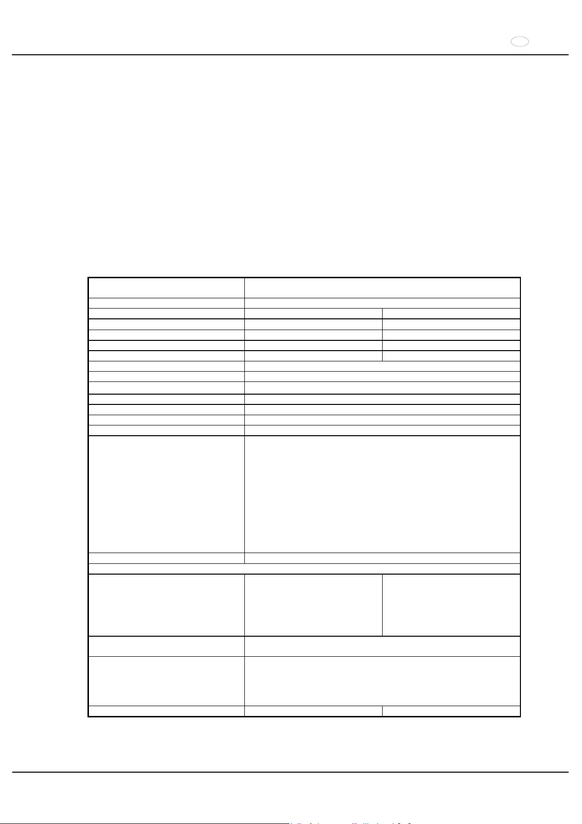
IT
55/104
1 Uso previsto
La presente macchina è un articolo medicale (centrifuga di laboratorio) ai sensi delle direttive IVD 98/79/CE. La
centrifuga separa sostanze e/o miscele di sostanze con una densità max. di 1,2 kg/dm³. Sono comprese anche
sostanze e miscele di origine umana. La centrifuga deve essere utilizzata unicamente per questo scopo. Qualsiasi
altro tipo di utilizzo è improprio. La ditta Andreas Hettich GmbH & Co. KG non risponde dei danni che ne
conseguono.
L’uso previsto comporta anche il rispetto di tutte le avvertenze delle istruzioni d’uso e l’esecuzione dei lavori di
ispezione e manutenzione stabiliti.
2 Rischi residui
La macchina è costruita secondo lo stato della tecnica e le regole tecniche di sicurezze riconosciute. L’utilizzo o il
trattamento non conformi possono causare pericoli per la vita e la salute dell’operatore o di terzi e anche danni
materiali e alla macchina. La macchina deve essere impiegata solo l’uso previsto e solo in perfetto stato di sicurezza.
Eliminare immediatamente i guasti che possono compromettere la sicurezza.
3 Dati tecnici
Costruttore
Andreas Hettich GmbH & Co. KG
D-78532 Tuttlingen
Modello ROTANTA 460
Tipo 5600 5600-01
Tensione di rete (r 10%) 208-240 V 1a
110-127 V 1~
Frequenza di rete 50 - 60 Hz 50 - 60 Hz
Potenza assorbita 1500 VA 1300 VA
Assorbimento di corrente 6.5 A 11 A
Tipo di refrigerante ---Capacità max. 4 x 750 ml
Densità permessa
1.2 kg/dm
3
Regime di rotazione (RPM) 15000
Accelerazione (RCF) 24400
Energia cinetica 41000 Nm
Obbligo di collaudo (BGR 261) si
Presupposti ambientali (EN 61010-1)
luogo di installazione
solo in interni
altezza
fino a 2000 metri sopra il livello del mare
temperatura ambiente
2°C fino a 40°C
umidità dell’aria
umidità relativa massima dell’aria 80% per temperature fino a 31°C, con
riduzione lineare fino al 50% dell’umidità relativa per una temperatura di
40°C.
Categoria di sovratensione
(IEC 60364-4-443)
,,
grado di imbrattamento
2
Classe di protezione
,
non adatto per l’impiego in ambiente a rischio di esplosione.
Compatibilità elettromagnetica
emissione di radiointerferenze
(schermatura)
EN 55011,
gruppo 1, classe B
EN 61000-3-3
FCC Class A
resistenza alle interferenze
EN 61000-6-1 ----
Livello di emissione acustica (in
funzione del rotore)
d 67 dB(A)
dimensioni
larghezza
554 mm
profondità
707 mm
altezza
453 mm
Peso 106 kg 115 kg
Page 56
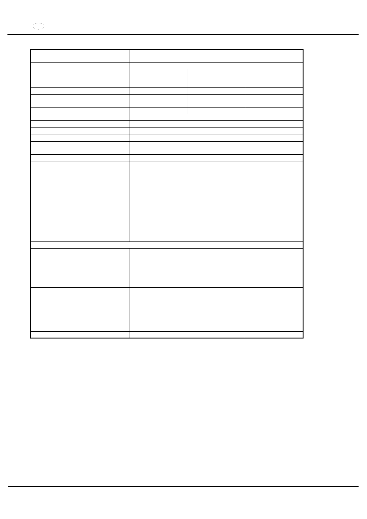
IT
56/104
Costruttore
Andreas Hettich GmbH & Co. KG
D-78532 Tuttlingen
Modello ROTANTA 460 R
Tipo
5605,
5605-20
5605-50
5605-07
5605-01,
5605-51
Tensione di rete (r 10%) 208-240 V 1a
208-240 V 1~ 110-127 V 1~
Frequenza di rete 50 - 60 Hz 60 Hz 60 Hz
Potenza assorbita 2400 VA 2200 VA 2000 VA
Assorbimento di corrente 10 A 10 A 16 A
Tipo di refrigerante R 404A
Capacità max. 4 x 750 ml
Densità permessa
1.2 kg/dm
3
Regime di rotazione (RPM) 15000
Accelerazione (RCF) 24400
Energia cinetica 51000 Nm
Obbligo di collaudo (BGR 261) si
Presupposti ambientali (EN 61010-1)
luogo di installazione
solo in interni
altezza
fino a 2000 metri sopra il livello del mare
temperatura ambiente
5°C fino a 35°C
umidità dell’aria
umidità relativa massima dell’aria 80% per temperature fino a 31°C, con
riduzione lineare fino al 50% dell’umidità relativa per una temperatura di
40°C.
Categoria di sovratensione
(IEC 60364-4-443)
,,
grado di imbrattamento
2
Classe di protezione
,
non adatto per l’impiego in ambiente a rischio di esplosione.
Compatibilità elettromagnetica
emissione di radiointerferenze
(schermatura)
EN 55011,
gruppo 1, classe B
EN 61000-3-3
FCC Class A
resistenza alle interferenze
EN 61000-6-1 ----
Livello di emissione acustica (in
funzione del rotore)
d 64 dB(A)
dimensioni
larghezza
770 mm
profondità
707 mm
altezza
453 mm
Peso 147 kg 156 kg
Page 57

IT
57/104
4 Indicazioni inerenti la sicurezza
Non si possono far valere diritti di garanzia presso il costruttore in caso di mancata osservanza delle
presenti indicazioni.
xPrima di mettere in funzione la centrifuga si devono leggere ed osservare le istruzioni per l'uso.
L’apparecchio può essere utilizzato solo da persone che abbiano letto e compreso le istruzioni d’uso.
x
Oltre alle istruzioni per l'uso, si devono osservare anche i regolamenti, relativi alla protezione antinfortunistica ed i
regolamenti tecnici, riconosciuti in materia di sicurezza del lavoro. Le istruzioni per l'uso vanno completate dalle
norme nazionali in vigore nel paese d'impiego, relative alla protezione antinfortunistica ed alla tutela ambientale.
xLa centrifuga è costruita in base all'attuale livello tecnologico e le regole di sicurezza conosciute.
La centrifuga può essere tuttavia fonte di pericolo per l'operatore o per terzi, se non viene utilizzata da
personale appositamente addestrato o se viene utilizzata in modo improprio o non conforme alla destinazione.
xLa centrifuga deve venire posizionata in modo sicuro.
xPrima di utilizzare la centrifuga, è necessario controllare che il rotore sia correttamente in sede.
xDurante un’operazione di centrifugazione, in una zona di sicurezza di 300 mm attorno alla centrifuga non deve
sostare alcuna persona, materiali pericolosi ed oggetti, in conformità alle norme IEC 61010-2-020.
xDurante l'esercizio bisogna evitare di muovere la centrifuga o di urtarvi contro.
xIn caso di guasto, ovvero del ripristino d'emergenza, non si deve assolutamente toccare il rotore.
xQuando la centrifuga passa da un ambiente freddo in uno caldo, per evitare danni dovuti alla condensa, lasciar
riscaldare la centrifuga per almeno 3 ore nell'ambiente caldo prima di collegarla alla rete, oppure portare la
centrifuga a temperatura d'esercizio mettendola in funzione per 30 minuti nell'ambiente freddo.
xDevono essere utilizzati esclusivamente i rotori e gli accessori omologati per questa apparecchiatura (vedere
capitolo "Anhang/Appendix, Rotoren und Zubehör/Rotors and accessories").
xIl rotore della centrifuga può essere caricato solo in conformità al capitolo " Carico del rotore".
xIn caso di centrifugazione con massimo numero di giri, la densità dei materiali o delle miscele di materiali non
deve superare il valore di composizione di 1,2 kg/dm3.
xNon è consentito l'uso di centrifughe non bilanciate in modo regolamentare.
xNon è permesso l’impiego della centrifuga in ambiente a pericolo di esplosione.
xE' proibito l'uso di una centrifuga con:
materiali infiammabili od esplosivi
materiali che possono reagire chimicamente tra loro con forte energia.
xSe vengono centrifugate sostanze pericolose o miscele di sostanze contaminate da micro organisimi tossici,
radioattivi o patogeni, l'utente dovrà prendere opportuni provvedimenti in materia.
Si devono fondamentalmente utilizzare contenitori per centrifugazione con tappi a vite speciali per sostanze
pericolose. Con materiali dei gruppi di rischio 3 e 4, oltre ai contenitori per centrifugazione chiudibili si deve
impiegare un sistema di sicurezza biologico (vedi manuale "Laboratory Biosafety Manual" dell'Organizzazione
mondiale per la salute).
La guarnizione biologica (guarnizione ad anello) di questo sistema di sicurezza biologico impedisce la fuoriuscita
delle goccioline e degli aerosol tra la sospensione ed il coperchio.
Se la sospensione di un sistema di sicurezza biologico viene usata senza coperchio, la guarnizione ad anello
deve essere rimossa dalla sospensione per evitare di danneggiarla durante il ciclo di centrifugazione. Le
guarnizioni ad anello danneggiate non possono più essere utilizzate per la chiusura a tenuta del sistema di
sicurezza biologico.
Senza l’impiego di un sistema di sicurezza biologico, una centrifuga non è microbiologicamente a tenuta in
conformità alla norma EN 61010-2-020.
Per quanto riguarda i sistemi biologici di sicurezza fornibili, rimandiamo al capitolo "Anhang/Appendix, Rotoren
und Zubehör/Rotors and accessories". Nel dubbio chiedere maggiori informazioni al produttore o importatore.
xNon è consentito il funzionamento della centrifuga con sostanze altamente corrosive che possono pregiudicare la
resistenza meccanica dei rotori, delle sospensioni e degli accessori.
xI rotori, le sospensioni e gli accessori che presentano forti segni di corrosione o danni meccanici, oppure la cui
durata d'impiego è scaduta, non devono più essere utilizzati.
xGli interventi di riparazione devono essere effettuati esclusivamente da una persona autorizzata dal costruttore.
xDevono essere impiegati solo ed esclusivamente pezzi di ricambio originali ed accessori autorizzati della ditta
Andreas Hettich GmbH & Co. KG.
xSono di validità le seguenti norme di sicurezza:
IEC 61010-1 e IEC 61010-2-020 come anche le loro nazionali varianti.
xLa sicurezza e l'affidabilità della centrifuga sono garantite solo se:
la centrifuga funziona in conformità con le istruzioni per l'uso
l'installazione elettrica sul luogo di posizionamento della centrifuga risponde ai requisiti previsti dalla IEC
i controlli previsti in base a BGV A1, BGR 261vengono eseguiti da un perito esperto in materia.
Page 58
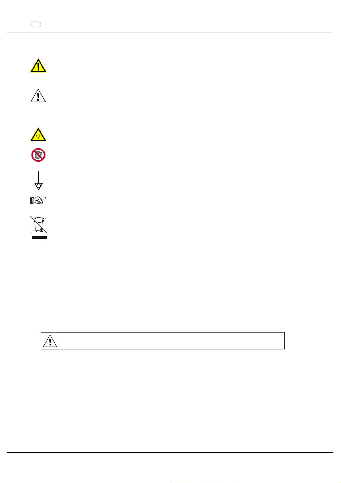
IT
58/104
5 Significato dei simboli
Simbolo sulla macchina:
Attenzione, punto pericoloso generico.
Prima di utilizzare la centrifuga, è assolutamente necessario leggere le istruzioni d’uso e rispettare le
avvertenze relative alla sicurezza!
Simbolo nelle istruzioni per il funzionamento:
Attenzione, punto pericoloso generico.
Questo simbolo contraddistingue le avvertenze relative alla sicurezza e indica situazioni potenzialmente
pericolose .
La mancata osservanza di tali avvertenze può causare danni materiali e personali.
Simbolo sulla macchina e nelle istruzioni d’uso:
Attenzione alle superfici molto calde.
Simbolo sulla macchina e nelle istruzioni d’uso:
Il caricatore di plastica, codice d’ordine N° 5091, deve essere utilizzato solo fino ad un massimo di
temperatura di 40°C.
Simbolo sulla macchina:
Equipotenziale: connettore a spina (connettore PA) per collegamento equipotenziale (solo nelle
centrifughe con connettore PA).
Simbolo nelle istruzioni per il funzionamento:
Questo simbolo indica argomenti importanti.
Simbolo sulla macchina e nelle istruzioni d’uso:
Simbolo per la raccolta separata delle apparecchiature elettriche ed elettroniche, in conformità alle
direttive 2002/96/CEE (WEEE). L’apparecchiatura appartiene al gruppo 8 (apparecchiature medicali).
Impiego nelle nazioni dell’Unione Europea, in Norvegia ed in Svizzera.
6 Contenuto della fornitura
1 cavo elettrico
1 chiave a forcella 2,5 mm
1 chiave a forcella 5 mm
1 grasso per perni portanti
1 istruzioni per l'uso
1 istruzioni per la sicurezza durante il trasporto
Rotore/i e i corrispondenti accessori vengono forniti in base alla commessa.
7 Disimballo della centrifuga
x
Levare il cartone verso l’alto e togliere l‘imbottitura.
x
Non sollevarla dalla copertura anteriore.
Considerare il peso della centrifuga, vedere capitolo “Dati tecnici“.
Con il numero adeguato di persone, sollevare la centrifuga da entrambi i lati e riporla sul tavolo di laboratorio.
Page 59
IT
59/104
8 Messa in funzione
x
In base alla normativa per gli strumenti di laboratorio IEC 61010-2-020 gli impianti domestici devono essere
provvisti di apposito sezionatore d’emergenza per l’interruzione della rete in caso di guasto.
L'interruttore deve essere posizionato distante dalla centrifuga, preferibilmente al di fuori della stanza in cui è
posizionata la centrifuga o vicino all'uscita.
xPorre la centrifuga in un posto adatto e livellarla. Per l’installazione deve essere rispettata la zona di sicurezza di
300 mm attorno alla centrifuga, richiesta in conformità alle norme IEC 61010-2-020.
Durante un’operazione di centrifugazione, in una zona di sicurezza di 300 mm attorno alla centrifuga
non deve sostare alcuna persona, materiali pericolosi ed oggetti, in conformità alle norme
IEC 61010-2-020.
xNon posizionare alcon oggetto in prossimita delle griglie di ventilazione
Mantenere un'area di ventilazione di 300 mm, intorno al condotto.
xCon la centrifuga del tipo 5605-20, collegare l’alimentazione dell’azoto in conformità alla documentazione
informativa AH5605-20XX allegata.
Il collegamento della centrifuga deve avvenire assolutamente in conformità con la documentazione
informativa allegata.
Prestate attenzione al foglio informativo allegato.
xCentrifuga con connettore PA:
all’occorrenza collegare il connettore PA sul retro dell’apparecchio con un sistema di collegamento
equipotenziale medico aggiuntivo.
xVerificare se la tensione di rete sia adatta all’indicazione riportata nella targhetta con i dati caratteristici.
xCollegare la centrifuga ad una spina standard di rete tramite il cavo di collegamento. Per la potenza massima
assorbita, vedere il capitolo "Dati tecnici".
xAccendere l’interruttore di rete. Posizione di accensione ",
".
Il tipo di macchina e la versione di programma vengono indicati, i LED sono illuminati. Dopo 8 secondi viene
indicato
OPEN OEFFNEN (aprire). Il LED è luminoso.
xAprire il coperchio.
I dati di centrifuga utilizzati per ultimi vengono illustrati.
xRimuovere la protezione per il trasporto, vedi le istruzioni per la sicurezza durante il trasporto".
9 Apertura e chiusura del coperchio
9.1 Apertura del coperchio
E' possibile aprire il coperchio solo se la centrifuga è accesa ed il rotore è fermo.
Se non dovesse essere possibile, vedi capitolo "Sblocco di emergenza".
xPremere il tasto sul pannello anteriore. Il coperchio si sblocca a motore, l’illuminazione del tasto e del LED
si spegne.
9.2 Chiusura del coperchio
Non afferrare con le dita tra il coperchio e il rivestimento.
Non chiudere il coperchio sbattendolo.
xPosizionare il coperchio e spingere leggermente verso il basso il bordo anteriore del coperchio. La chiusura
avviene grazie ad un sistema motorizzato. Il tasto luminoso
e il LED si accendono.
Page 60
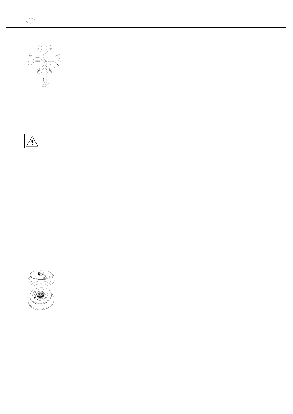
IT
60/104
10 Installazione e disinstallazione del rotore
A
B
C
D
x
Pulire l’albero motore (C) ed il foro del rotore (A), successivamente lubrificare
leggermente l’albero motore. Particelle di sporco tra l’albero motore ed il rotore
impediscono un normale funzionamento del rotore e causano un movimento rumoroso.
xPorre il rotore in senso verticale sull’albero motore. Il meccanismo di trascinamento
dell’albero motore (D) deve trovarsi nella scanalatura del rotore (B). Sul rotore è
segnato l’allineamento della scanalatura.
xStringere il dado di registrazione di tensione del rotore con l’aiuto della chiave inclusa
nel cartone, ruotandola in senso orario.
xVerificare che il rotore sia fissato.
xDisinstallare il rotore: svitare il dado di registrazione di tensione, ruotandolo in senso
anti-orario fino a che non abbia raggiunto il punto di completo svitamento. Con il punto
di svitamento completo, il rotore si può smontare dal cono dell’albero motore. Girare il
dado di registrazione di tensione fino a che diventi possibile smontare il rotore
dall’albero motore.
11 Carico del rotore
Lo standard dei recipienti di vetro centrifugati sono da caricare fino a RCF 4000 (DIN 58970 capoverso 2).
xVerificare che il rotore sia fissato.
xNel caso di rotori oscillanti, tutti i siti del rotore devono essere muniti di ganci uguali. Particolari ganci sono
contrassegnati con il numero del sito del rotore. Questi ganci devono essere applicati solo nel relativo sito del
rotore.
xI rotori ed i ganci devono essere caricati esclusivamente in modo simmetrico. Per le combinazioni permesse
vedere capitolo "Anhang/Appendix, Rotoren und Zubehör/Rotors and accessories".
In caso di rotori angolari devono essere caricati tutti i possibili siti del rotore, vedere il capitolo
"Anhang/Appendix, Rotoren und Zubehör/Rotors and accessories".
xIn determinate sospensioni è indicato il peso del carico massimo e il peso massimo della sospensione
completamente attrezzata. Questi pesi non devono essere superati. Il peso indicato per il carico massimo
comprende il peso completo di riduttore, supporto, provetta da centrifuga e contenuto.
xNel caso di contenitori con inserimenti in gomma, deve essere sempre mantenuto lo stesso numero di
inserimenti in gomma sotto i contenitori di centrifugazione.
xRiempire i recipienti della centrifuga all‘esterno della centrifuga stessa.
xFare attenzione che non giunga alcuna sostanza liquida nella camera di centrifugazione durante il carico ed
l’oscillazione dei ganci.
xIl carico massimo dei recipienti della centrifuga non deve essere superiore a quello indicato dalla casa
costruttrice.
xPer limitare al massimo le differenze di peso all’interno dei contenitori di centrifugazione, bisogna fare attenzione
che siano riempiti tutti in modo uguale.
12 Chiudere i rotori ad angolo a tenuta ermetica in modo da impedire la fuoriuscita di aerosol
Per garantire la tenuta agli aerosol, il coperchio di un rotore angolare a tenuta di aerosol
deve essere ben chiuso.
Ciò è possibile con l’ausilio della chiave in dotazione, che viene inserita attraverso il foro
della manopola. Se nella manopola non è presente alcun foro, il coperchio deve essere
chiuso manualmente, ruotandolo in senso orario.
Per i rotori ad angolo anti-aerosol disponibili, vedi capitolo "Anhang/Appendix, Rotoren und
Zubehör/Rotors and accessories“.
13 Elementi di operazione e visualizzazione
Vedere illustrazione alla pagina 2
Fig. 2, Fig. 3: Display
Page 61
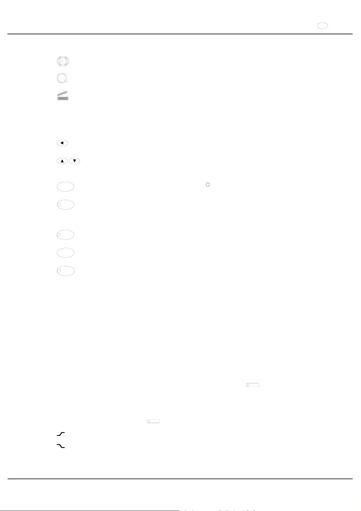
IT
61/104
13.1 Simboli del display
Indicazione di squilibrio. L‘indicazione di squilibrio si illumina nel caso in cui la differenza di peso
permissibile nel carico del rotore sia stata superata.
Indicazione di rotazione. L‘indicazionedi rotazione si illumina durante la centrifugazione, fino a che il rotore
giri.
Indicazione del coperchio. L‘indicazionedel coperchio si illumina quando il coperchio è chiuso e serrato.
Durante la centrifugazione, l‘indicazione del coperchio si spegne .
Errori di operazione (o guasti riscontrati) vengono segnalati nel display (vedere capitolo "Guasti").
13.2 Tasti del display
Tasto di selezione per selezionare i singoli parametri.
Premendo successivamente questo tasto viene selezionato il parametro successivo.
Premendo i tasti con la freccia viene aumentato o diminuito il valore di un parametro selezionato
precedentemente. Tenendo un tasto con la freccia premuto, si può aumentare o diminuire il valore più
rapidamente.
START
Iniziare la centrifugazione. L‘indicazione di rotazione si illumina.
Accettazione di inserimenti e modificazioni.
STOP
Finire la centrifugazione.
Il rotore rallenta gradualmente con il livello di frenatura preselezionato. Il segnale luminoso rimane acceso
fino a che il rotore non si arresta.
Per attivare L’ARRESTO DI EMERGENZA, premere due volte questo tasto.
RCF
Selezionare l‘indicazione RCF.
Il segnale luminoso nel tasto è acceso.
IMPULS
Centrifugazione breve.
La centrifugazione avviene fino a che il tasto viene tenuto premuto.
PROG
Salvare e richiamare i programmi.
Premendo successivamente il tasto, compaiono i programmi successivi (1 - 2 - 3 - #)
13.3 Possibilità di regolazione
t/min Regolabile da 1 a 99 min, in passi da 1 min.
t/sec Regolabile da 1 a 59 s, in passi da 1 sec.
Corsa continua "f".
RPM Numero di giri. È impostabile un valore numerico di 500 rpm fino al numero di giri massimo del rotore. Per il
numero di giri massimo del rotore, vedi capitolo "Anhang/Appendix, Rotoren und Zubehör/Rotors and
accessories“. Regolabile da 500 rpm a 10000 rpm ad intervalli di 10 e, a partire da 10000 rpm, fino al
numero di giri massimo ad intervalli di 100.
RAD/mm Raggio di centrifugazione. Inserimento in mm. Per il raggio di centrifugazione, vedere capitolo
"Anhang/Appendix, Rotoren und Zubehör/Rotors and accessories". L’inserimento del raggio è possibile
solo se l‘indicazione RCF è selezionata (il segnale luminoso del tasto
RCF
è acceso).
RCF Acceleramento relativo della centrifuga. È impostabile un valore numerico con il quale si ottiene un numero
di giri compreso tra 500 rpm ed il numero di giri massimo del rotore. Regolabile fino a 100 in passi da 1 e
da 100 in passi da 10 . Il valore RCF viene automaticamente arrotondato per eccesso o per difetto alpasso
del numero di giri. L’inserimento del RCF è possibile solo se l‘indicazione RCF è stata selezionata ((il
segnale luminoso del tasto
RCF
è acceso).
Livelli di inizio 1 - 9. Livello 9 = tempo di avvio più breve, livello 1 = tempo di avvio più lungo.
Livelli di frenatura 0 - 9. Livello 9 = tempo di arresto più breve, livello 1 = tempo di arresto più lungo
Livello 0 = tempo di arresto più lungo (arresto non frenato).
Page 62
IT
62/104
T/°C Valore nominale di temperatura (solo per centrifuga con raffreddamento). Regolabile da -20°C fino a
+40°C, in passi da 1°C (regolabile con opzione di riscaldamento/ raffreddamento da –20 °C a +60 °C /
+90°C. La temperatura minima raggiungibile dipende dal rotore (vedere capitolo "Anhang/Appendix,
Rotoren und Zubehör/Rotors and accessories").
PROG Numero del programma. Possono essere salvati 3 programmi (Memoria programmi 1 - 2 - 3). La posizione
di memoria programma # funge da memoria transitoria per impostazionimodificate.
14 Inserire i parametri di centrifugazione
Nel caso in cui, dopo aver selezionato oppure durante l‘inserimento di parametri, non venga premuto per 8
secondi alcun tasto, vengono indicati i valori precedenti. L’inserimento dei parametri deve essere poi eseguita
nuovamente.
xCon il tasto
RCF
selezionare l‘indicazione RPM oppure RCF. Se l‘indicazione RCF è stata selezionata il
segnale luminoso del tasto
RCF
è acceso.
xSelezionare con il tasto
i parametri desiderati e regolare con i tasti
Per impostare il funzionamento continuo, i parametri
t/min e t/sec devono essere azzerati con il tasto
. Il
funzionamento continuo è indicato sul display dal simbolo "f
".
xDopo l’inserimento di tutti i parametri, premere il tasto
START
per salvare gli inserimenti nella memoria di
programma
# . Per conferma, viene indicata per alcuni secondi la dicitura
ok .
I dati sulla posizione di memoria programma # vengono soprascritti con ogni nuovo inserimento di parametri e
premendo il tasto
START
15 Programmazione
15.1 Inserimento/Variazione del programma
x
Selezionare con il tasto
RCF
le indicazioni RPM oppure RCF. Se l‘indicazione RCF è stata selezionata, il
segnale luminoso del tasto
RCF
è acceso.
xSelezionare con il tasto
il parametro desiderato e regolare con i tasti
xSelezionare con il tasto il parametro PROG e regolare con i tasti la posizione di memoria programma
desiderata. Il segnale luminoso del tasto
PROG
è acceso.
xPremere il tasto
PROG
per salvare le impostazioni nella posizione di memoria programma desiderata. Per
conferma viene indicata per alcuni secondi la dicitura
ok .
15.2 Richiamo del programma
xSelezionare la posizione di memoria programma desiderata con il tasto
PROG
I dati di centrifugazione della posizione di memoria programma selezionata vengono indicati.
xI parametri possono essere verificati tramite il tasto
.
16 Centrifugazione
Durante un’operazione di centrifugazione, in una zona di sicurezza di 300 mm attorno alla centrifuga non deve
sostare alcuna persona, materiali pericolosi ed oggetti, in conformità alle norme IEC 61010-2-020.
Nel caso in cui la differenza di peso permissibile nel caricamento del rotore venga superata, si ferma
l’azionamento durante l‘avvio, si illumina l‘indicazione di squilibrio e compare la dicitura
IMBALANCE.
Se il numero di giri nel programma selezionato è più elevato del numero di giri massimo del rotore, non è
possibile avviare un ciclo di centrifugazione. Compare la dicitura N > ROTOR MAX (vedere capitolo "Guasti").
Una corsa di centrifugazione può essere interrotta in ogni momento premendo il tasto
STOP
Durante la corsa di centrifugazione, può essere selezionato e modificato ogni tipo di parametro (vedere
capitolo "Inserire i parametri di centrifugazione").
Con il tasto
RCF
è possibile commutare in ogni momento le indicazioni RPM e RCF. Se viene usata
l’indicazione RCF, è necessario inserire il raggio di centrifugazione.
Se compaiono le diciture
OPEN OEFFNEN (=APRIRE), è possibile un operazione della centrifuga solo
dopo aver aperto una volta il coperchio.
Se viene visualizzato R xx n-max xxxxx, non ha avuto luogo alcun processo di centrifugazione in quanto è
stato sostituito il rotore, vedere il capitolo " Riconoscimento del rotore ".
xAccendere l’interruttore di rete. Posizione di accensione ,.
xCaricare il rotore e chiudere il coperchio della centrifuga.
Page 63

IT
63/104
16.1 Centrifugazione con tempo preimpostato
x
Selezionare il tempo oppure richiamare un programma con tempo preimpostato (vedere capitolo "Inserire i
parametri di centrifugazione" oppure "Richiamo del programma“
xPremere il tasto
START
drücken. L’indicazione di rotazione è accesa fino a che il rotore gira..
xPassato il tempo o con l‘interruzione della corsa di centrifugazione premendo il tasto
STOP
, avviene l’arresto
con il livello di frenatura selezionato. Il livello di frenatura viena indicato..
Durante la corsa di centrifugazione compaiono il numero di giri del rotore, il valore RCF risultante, la temperatura
delle provette (solo per centrifuga con raffreddamento) ed il tempo rimanente.
16.2 Corsa continua
xImpostazione il simbolo f oppure richiamare il programma di corsa continua (vedere capitolo "Inserire i
parametri di centrifugazione" oppure "Richiamo del programma“)
xPremere il tasto
START
. L‘indicazione di rotazione illuminaa fino a che il rotore gira. Il conteggio del tempo inizia
da 00:00.
xPremere il tasto
STOP
per terminare la centrifugazione. L’arresto avviene con il livello di frenatura selezionato. Il
livello di frenatura viene indicato.
Durante la centrifugazione compaiono il numero di giri del rotore, il valore RCF risultante, la temperatura delle
provette (solo per centrifuga con raffreddamento) ed il tempo intercorso.
16.3 Centrifugazione breve
xTenere premuto il tasto
IMPULS
L‘indicazione di rotazione illumina fino a che il rotore gira.
xTogliere il dito dal tasto
IMPULS
per terminare la corsa di centrifugazione. L’arresto avviene con il livello di
frenatura selezionato. Il livello di frenatura viene indicato.
Durante la centrifugazione compaiono il numero di giri del rotore, il valore RCF risultante, la temperatura delle
provette (solo per centrifuga con raffreddamento) ed il tempo rimanente.
17 Arresto di emergenza
xPremere 2 volte il tasto
STOP
Con l’arresto di emergenza l’arresto avviene con il livello di frenatura 9 (arresto più breve). Il livello di frenatura 9
viene indicato.
Con il livello di frenatura preimpostato sullo 0, il tempo di arresto, per motivi tecnici, è superiore a quello raggiunto
con il livello di frenatura 9.
18 Segnale acustico
Il segnale acustico si attiva quando:
xcon il verificarsi di un guasto con intervallo di 2 sec
xdopo il terminare della corsa di centrifugazione e arresto del rotore con intervallo di 30 secondi
Aprendo il coperchio oppure premendo un tasto qualsiasi, il segnale acustico cessa.
Il segnale che si attiva in seguito alla cessazione della corsa di centrifugazione, può essere attivato o disattivato,
raggiunto l’arresto del rotore, in modo seguente:
xTenere premuto il tasto
per 8 secondi.
Dopo 8 sec. compare la dicitura
SOUND / BELL.
xImpostare con il tasto
oppure OFF (disinserito) oppure ON (inserito).
xPremere il tasto
START
per salvare le impostazioni. Per conferma, compare per alcuni secondi la dicitura
ok .
19 Consultazione delle ore di funzionamento
La consultazione delle ore di funzionamento è possibile solo con rotore in posizione di arresto.
xTenere premuto il tasto
per 8 secondi.
Dopo 8 sec. Compare la dicitura
SOUND / BELL.
xPremere nuovamente il tasto
Compaiono le ore di funzionamento della centrifuga (
CONTROL: ).
xPer uscire dalla consultazione delle ore di funzionamento premere il tasto
oppure
Page 64
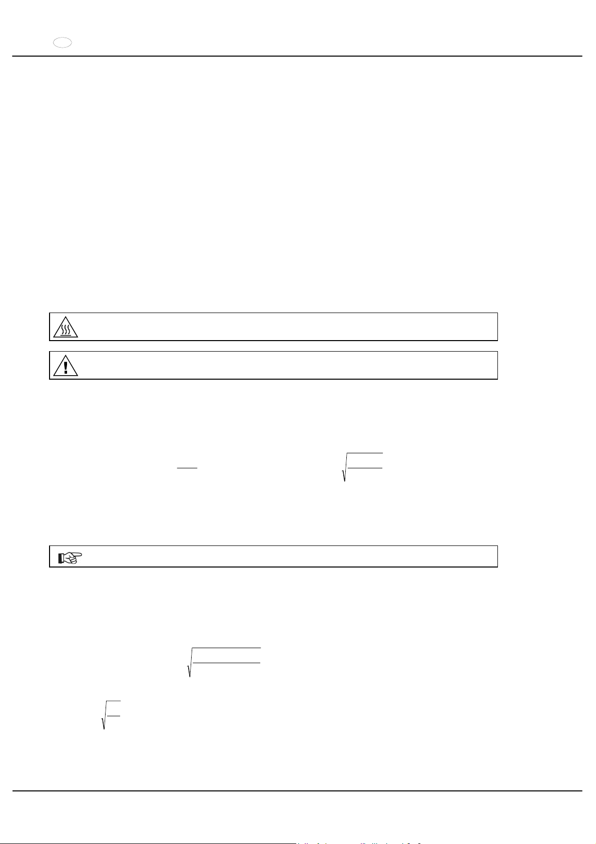
IT
64/104
20 Raffreddamento (solo per centrifuga con raffreddamento)
Il valore nominale di temperatura può essere selezionata da -20°C fino a +40°C. Nelle centrifughe con l’opzione di
riscaldamento/ raffreddamento, il valore nominale della temperatura è regolabile da –20 °C a +60 °C / +90°C. La
temperatura minima raggiungibile dipende dal rotore (vedere capitolo "Anhang/Appendix, Rotoren und
Zubehör/Rotors and accessories").
20.1 Raffreddamento-Standby
Con l’arresto del rotore e coperchio chiuso, la camera di centrifugazione viene raffreddata alla temperatura
selezionata. Nel display compare il valore nominale di temperatura.
20.2 Pre-raffreddamento del rotore
Per una rapida prerefrigerazione del rotore non carico e degli accessori è consigliabile effettuare un ciclo di
centrifugazione con le impostazioni funzionamento continuo ed un numero di giri all'incirca del 20% del numero di giri
massimo del rotore.
21 Riscaldamento (solo per centrifughe con opzione di riscaldamento/ raffreddamento)
Durante il processo di centrifuga, in caso di necessità, il vano di centrifugazione può essere riscaldato alla
temperatura preimpostata.
Al fermo del rotore, il riscaldamento è spento.
Pericolo di combustione! La temperatura superficiale dell’elemento riscaldante nella camera di
centrifugazione della centrifuga può raggiungere 500°C / 932°F. Non toccare l’elemento riscaldante.
Il caricatore di plastica, codice d’ordine N° 5091, deve essere utilizzato solo fino ad un massimo di
temperatura di 40°C.
22 Accelerazione centrifuga relativa (RCF)
L’accelerazione centrifuga relativa (RCF) è indicata come un multiplo dell’accelerazione terrestre (g). È un valore
numerico privo di unità e funge per paragonare le prestazioni di separazione de sedimentazione.
Il calcolo viene eseguito in base alla formula:
1,118r
2
1000
RPM
RCF
uu
¸
¹
·
¨
©
§
1000
1,118r
RCF
RPM
u
u
RCF = accelerazione centrifuga relativa
RPM = numero dei giri
r = raggio di centrifugazione in mm = distanza dal centro dell’asse di rotazione fino al fondo del recipiente di
centrifugazione. Raggio di centrifugazione vedi al capitolo
”Anhang/Appendix, Rotoren und Zubehör/Rotors and accessories”.
L’accelerazione centrifuga relativa (RCF) dipende dal numero dei giri e dal raggio di centrifugazione.
23 Centrifugazione di materiali con elevata densità
I rotori sono costruiti in modo da poter centrifugare delle sostanze dalla densità mediamente omogenea di max. 1,2
kg/dm3 , con il numero di giri indicato.
Sostanze di maggiore densità devono essere centrifugate con un numero di giri ridotto.
Il numero di giri consentito si calcola con la formula seguente:
nominalegiridinumerox
maggioreàdensit
2,1
=)n(ridottogiridinumero red
p.es.: RPM 4000, densità 1,6 kg/dm
3
RPM3464=4000 x
1,6
1,2
=n
red
In caso di dubbio, rivolgersi al costruttore per maggiori informazioni.
Page 65
IT
65/104
24 Riconoscimento del rotore
Con l’inizio di ogni corsa di centrifugazione, avviene il riconoscimento del rotore installato.
Dopo la sostituzione del rotore, l’azionamento si disinserisce e sono visualizzati il codice del rotore (R xx) e la
velocità massima del rotore (n-max=xxxxx).
L’ulteriore utilizzo della centrifuga è possibile solo dopo avere aperto una volta il coperchio.
Se dopo un cambio del rotore il numero di giri massimo del rotore è inferiore al numero di giri impostato, la
velocità viene limitata al numero di giri massimo del rotore.
25 Sblocco di emergenza
In caso di una caduta di tensione, il coperchio non può essere sbloccato a motore. Deve essere effettuata
manualmente uno sblocco di emergenza.
Per lo sblocco di emergenza, disconnettere la centrifuga dalla rete elettrica.
Aprire il coperchio solo con l’arresto del rotore.
Vedere illustrazione alla pagina 2.
xDisinserire l’interruttore di rete (posizione interruttore "0").
xGuardare attraverso la finestra presente nel coperchio per assicurarsi che il rotore sia fermo.
xIntrodurre la chiave per viti Allen nel foro (Fig. 1, A) e ruotarla con cautela di mezzo giro in senso orario, fino ad
aprire il coperchio.
xStrappare la vita senza testa esagonale dal foro.
xDopo la riaccensione della centrifuga, premere il tasto
, in modo che la chiusura a mezzo di motore del
coperchio riprenda nuovamente la posizione iniziale (apertura).
26 Pulizia e manutenzione
Prima della pulizia, staccare la presa di corrente.
Prima di iniziare un procedimento di pulizia e decontaminazione diverso da quello consigliato dal
produttore, l’utilizzatore deve accertarsi presso il produttore che tale procedimento previsto non rechi danno
all’apparecchio.
xDevono essere impiegati detersivi e disinfettanti con valore PH compreso tra 5 e 8. Evitare detersivi alcalini con
valore PH superiore di 8.
xSeguire attentamente le indicazioni speciali del produttore sull’impiego di detersivi e disinfettanti, al fine di evitare
qualsiasi fenomeno di corrosione.
26.1 Centrifuga
xPulire regolarmente il corpo della centrifuga e la camera di centrifugazione e impiegare all'occorrenza sapone o
un detergente delicato e un panno umido. Ciò serve da un lato per l’igiene e dall’altro lato per evitare la
corrosione causata da impurità incrostate.
xIn caso di formazione di acqua di condensa, asciugare la camera di centrifugazione pulendola con un panno
assorbente.
xIn presenza di materiale infettivo nella camera di centrifugazione si deve disinfettarla immediatamente. Per la
disinfezione delle superfici raccomandiamo Bacillol® Plus della ditta Bode Chemie Hamburg o Biocidal ZF
TM
della ditta WAK-Chemie Medical GmbH Steinbach.
xLubrificare leggermente la guarnizione in gomma della camera di centrifugazione dopo averla pulita.
Page 66
IT
66/104
26.2 Rotori ed accessori
x
Per evitare che il materiale si corroda o subisca variazione, i rotori e i pezzi accessori devono essere puliti
regolarmente con sapone o un detergente delicato e un panno umido. Si consiglia una pulizia settimanale
oppure meglio dopo ogni utilizzo.
xIn caso di sporco costituito da materiale patogeno o radioattivo nel rotore o nelle parti accessorie, bisogna
effettuare una pulizia idonea. Per la disinfezione si raccomanda Helipur® H plus N della ditta B. Braun
Melsungen. Per la rimozione di materiale radioattivo si raccomanda decon neutracon® della ditta Decon
Laboratories Limited.
xDopo la pulizia, i rotori e le parti accessorie devono essere immediatamente asciugati.
xI rotori ad angolo, i contenitori e i supporti in alluminio devono essere ingrassati leggermente con grasso privo
d’acidi come ad esempio vaselina quando sono ben asciutti.
xIn caso di rotori a tenuta di areosol e di sistemi di Bio-Sicurezza (vedi capitolo "Anhang/Appendix, Rotoren und
Zubehör/Rotors and accessories"), gli anelli di tenuta devono essere controllati e puliti regolarmente
(settimanalmente). In presenza di crepe, parti fragili o logorio, l’anello di tenuta deve essere subito sostituito. Per
evitare una distorsione dell’anello di guarnizione durante l’apertura e la chiusura del coperchio, l’anello delle
guarnizione deve essere ingrassato con grasso privo di acidi, come ad esempio vaselina.
xPer evitare la corrosione causata dall’umidità tra il rotore e l’albero motore, si deve provvedere almeno una volta
al mese di smontare il rotore, pulirlo e di lubrificare leggermente l’albero motore.
xBisogna verificare mensilmente che i rotori e le parti accessorie non siano danneggiati dalla corrosione.
Rotori ed accessori non devono essere più utilizzati se presentano consumo o corrosione.
xVerificare settimanalmente la posizione del rotore.
26.2.1 Perni di trascinamento
In rotori oscillanti, i perni di trascinamento devono essere lubrificati regolarmente (Grasso lubrificante Hettich no.
d’ord. 4051) per consentire un’oscillazione equilibrata dei ganci.
26.2.2 Rotori e accessori con durata d'impiego limitata
L'impiego di determinati rotori, sospensioni ed accessori è limitato nel tempo.
Questi sono contrassegnati con la data di scadenza, per esempio: "einsetzbar bis Ende: / usable until end of:
,V. Quartal 2011" (utilizzabile fino a fine: ,V° trimestre 2011).
Una volta raggiunta la relativa data di scadenza indicata, per motivi di sicurezza i rotori, le sospensioni e gli
accessori non devono più essere utilizzati.
26.3 Mantenere in autoclave
I rotori basculanti, i rotori angolari di alluminio, le sospensioni di metallo, i coperchi con chiusura ermetica anticontaminazione biologica, come pure i telai e le riduzioni possono essere trattati in autoclave a 121° C / 250° F
(20 minuti).
In caso di dubbio occorre informarsi presso la casa produttrice.
Il coperchio del rotore ed il contenitore devono essere staccati prima di essere riposti in autoclave.
La conservazione in autoclave accelera il processo di invecchiamento del materiale in plastica. Inoltre può
causare variazioni di colore nel materiale in plastica.
Dopo il trattamento in autoclave, consigliamo di sostituire gli anelli di guarnizione dei rotori ermetici
all’aerosol e dei sistemi di sicurezza biologici.
26.4 Contenitori centrifuga
xIn caso di mancanza di tenuta o dopo la rottura dei contenitori per centrifugazione, rimuovere completamente i
frammenti dei contenitori, le schegge di vetro e il centrifugato fuoriuscito.
xDopo la rottura di parti in vetro, sostituire gli inserti di gomma e i manicotti di plastica dei rotori.
Le schegge di vetro rimaste causano ulteriori rotture!
xNel caso di materiale infettivo, bisogna provvedere immediatamente ad una disinfezione.
Page 67
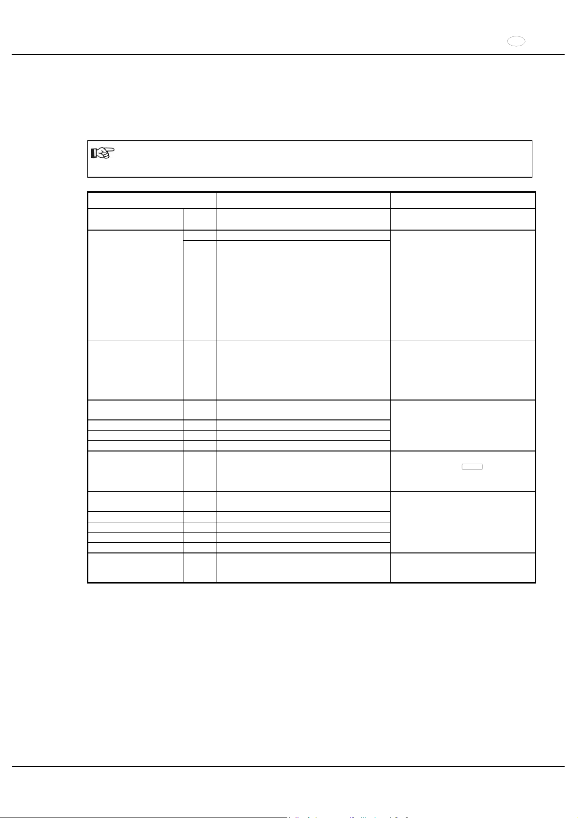
IT
67/104
27 Guasti
Se non si riesce a eliminare l’errore seguendo le indicazioni della tabella guasti, informare il servizio assistenza
clienti.
Pregasi comunicare il tipo di centrifuga ed il numero di fabbricazione che sono riportati nella targhetta con i dati
caratteristici della centrifuga.
Esecuzione di un RESET RETE:
Disinserire l’interruttore di rete (posizione interruttore "0").
Attendere almeno 10 secondi quindi reinserire l’interruttore di rete (posizione interruttore ",").
Visualizzazione/guasto Causa Eliminazione
Nessuna
visualizzazione
--- Non c'è tensione.
Scatto fusibile sovraccorrente.
Controllare alimentatore elettrico.
Interruttore di rete ON.
01 Tachimetro difettoso TACHO - ERROR
02 Rotore non installato
Motore, convertitore, azionatore difettosi.
Aprire il coperchio.
Disinserire l’interruttore di rete
(posizione interruttore "0").
Attendere per almeno 10
secondi.
Girare energicamente a mano il
rotore.
Reinserire l’interruttore di rete
(posizione interruttore ",").
Durante l’inserimento il rotore
deve girare
IMBALANCE --- Il rotore è caricato in modo non uniforme.
Aprire il coperchio.
Controllare il caricamento del
rotore, vedere il capitolo "Carico
del rotore".
Ripetere il ciclo di centrifuga-
zione.
CONTROL - ERROR 04,
06 - 09
Errore blocco coperchio, ovvero chiusura
coperchio.
N > MAX 05 N° giri eccedente
N < MIN 13 N° giri insufficiente
ROTORCODE 10 Errore codifica rotore
Esecuzione di un RESET RETE.
MAINS INTERRUPT --- Interruzione di rete durante il ciclo di
centrifugazione. (Il ciclo di centrifugazione
non viene terminato.)
Aprire il coperchio.
Premere tasto
START
.
All’occorrenza ripetere il ciclo di
centrifugazione.
VERSIONS-ERROR 12 Non c'è corrispondenza tra i componenti
elettronici
CONTROL-ERROR 21 - 27 Errore/guasto lato comandi
SER I/O - ERROR 30 - 38 Errore/guasto interfaccia
° C * - ERROR 50 - 56 Errore/guasto raffreddamento
FU / CCI - ERROR 60 - 83 Errore/guasto controllo motore
Esecuzione di un RESET RETE.
N > ROTOR MAX --- Il numero di giri nel programma selezionato è
superiore al numero di giri massimo del
rotore.
Verificare e correggere la velocità
nel programma selezionato.
Page 68

IT
68/104
28 Accettazione di centrifughe da riparare
Nel caso in cui la centrifuga debba essere rispedita al produttore per una eventuale riparazione, prima della
spedizione deve essere decontaminata e pulita a fondo a salvaguardia delle persone, dell’ambiente e del materiale.
Ci riserviamo di accettare centrifughe contaminate.
Eventuali costi di pulizia e disinfezione verranno fatturati al cliente.
Contiamo a questo riguardo sulla vostra comprensione.
29 Smaltimento
Per lo smaltimento dell'apparecchio osservare le rispettive norme di legge.
Ai sensi della direttiva 2002/96/CE (RAEE) tutti gli apparecchi forniti dopo il 13/08/2005 non possono più essere
smaltiti con i rifiuti domestici. Questo apparecchio appartiene alla categoria 8 (Dispositivi medicali) ed è classificato
nel settore Business-to-Business.
Il simbolo della pattumiera cancellata con una croce indica che l'apparecchio non deve essere smaltito
con i rifiuti domestici.
Le norme per lo smaltimento possono essere differenti nei singoli paesi UE. In caso di necessità rivolgersi
al proprio rivenditore.
Page 69
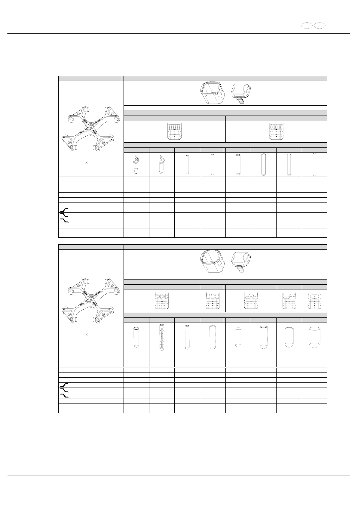
DE EN
69/104
30 Anhang / Appendix
30.1 Rotoren und Zubehör / Rotors and accessories
5624 5625 + 5627
+
mit Bioabdichtung / with bio-containment 12)
Gestell / frame
4730 4732
Röhrchen / tube
2078 0536 ---- ---- ---- 0553 0501 0578
Ausschwingrotor 4-fach /
Swing out rotor 4-times
90°
Kapazität / capacity ml 1,5 2,0 3 4 4 5 6 7
Maße / dimensions x L
mm 11 x 38 11 x 38 10 x 60 10 x 88 12 x 60 12 x 75 12 x 82 12 x 100
Anzahl p. Rotor / number p. rotor 224 224 120 120 80 80 80 80
Drehzahl / speed RPM 4600 4600 4600 4600 4600 4600 4600 4600
RZB / RCF
3)
3572/4637 3572/4637 4637 4637 4637 4637 4637 4637
Radius / radius mm 151/196 151/196 196 196 196 196 196 196
9 (97%)
sec 90 90 90 90 90 90 90 90
9
sec 95 95 95 95 95 95 95 95
0
sec 960 960 960 960 960 960 960 960
Temperatur / temperature °C 1) 4 4 4 4 4 4 4 4
Probenerwärmung/Sample
temp. rise
K2) 19 19 19 19 19 19 19 19
5624 5625 + 5627
+
mit Bioabdichtung / with bio-containment 12)
Gestell / frame
4733 4734 4735 4737 4738
Röhrchen / tube
2079 0518 0507 0519 0548 0521 0526 0530
Ausschwingrotor 4-fach /
Swing out rotor 4-times
90°
Kapazität / capacity ml 10 15 15 25 75 75 100 250
Maße / dimensions x L
mm 17 x 70 17 x 100 17 x 100 24 x 100 35 x 105 34 x 100 44 x 100 65 x 115
Anzahl p. Rotor / number p. rotor 68 68 68 24 12 12 8 4
Drehzahl / speed RPM 4600 4600 4600 4600 4600 4600 4600 4600
RZB / RCF
3)
4637 4637 4637 4637 4495 4495 4637 4495
Radius / radius mm 196 196 196 196 190 190 196 190
9 (97%)
sec 90 90 90 90 90 90 90 90
9
sec 95 95 95 95 95 95 95 95
0
sec 960 960 960 960 960 960 960 960
Temperatur / temperature °C 1) 4 4 4 4 4 4 4 4
Probenerwärmung/Sample
temp. rise
K2) 19 19 19 19 19 19 19 19
1) Niedrigste Probentemperatur bei Vorkühlung und maximaler
Drehzahl (nur bei Kühlzentrifuge)
1) Lowest sample temperature with pre-cooling and maximum speed (only
with cooling centrifuges)
2) Probenerwärmung bei maximaler Drehzahl und 1 Stunde
Laufzeit (nur bei Zentrifuge ohne Kühlung)
2) Sample temp. rise during maximum speed and 1 hour running time (only
with centrifuges without cooling)
3) Zentrifugiergefäße aus Glas nur belastbar bis RZB 4000 3) Centrifuge containers of glass will not stand RCF values exceeding 4000
12) Nach DIN EN 61010, Teil 2 – 020. Die Hinweise für Bio-Sicher-
heitssysteme in den Kapiteln "Sicherheitshinweise" und "Pflege
und Wartung" beachten.
12) in conformity with DIN EN 61010, part 2 – 020. Observe the notes for bio
safety systems in chapters "Notes on safety" and "Maintenance and
servicing".
Page 70
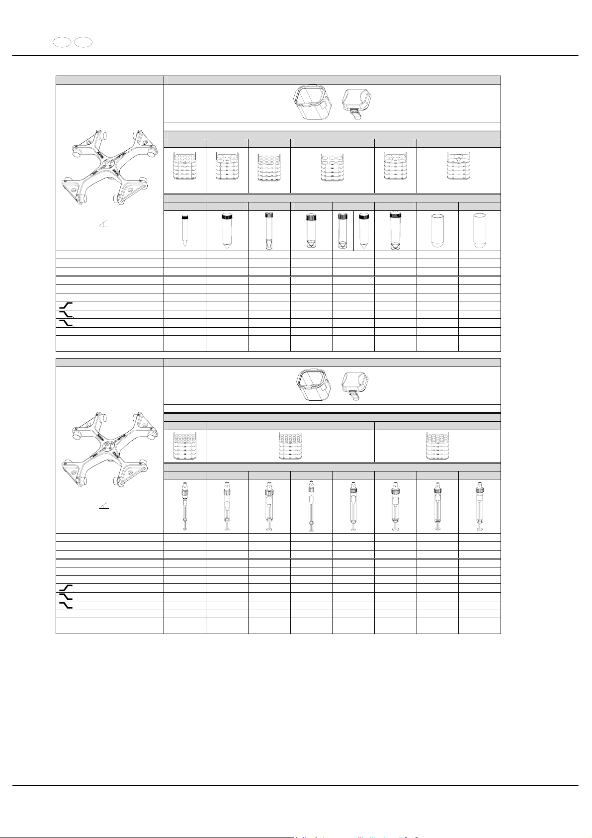
DE EN
70/104
5624 5625 + 5627
+
mit Bioabdichtung / with bio-containment 12)
Gestell / frame
4739 4740 4739 11) 4734 4740 11) 4736
Röhrchen / tube
0509 0513 ---- ---- ---- ---- 0549 0523
Ausschwingrotor 4-fach /
Swing out rotor 4-times
90°
Kapazität / capacity ml 15 50 12 25 30 50 85 100
Maße / dimensions x L
mm 17 x 120 30 x 115 17 x 100 25 x 90 25 x 110 30 x 115 38 x 106 40 x 115
Anzahl p. Rotor / number p. rotor 48 20 48 24 24 20 12 12
Drehzahl / speed RPM 4600 4600 4600 4600 4600 4600 4600 4600
RZB / RCF
3)
4637 4637 4637 4637 4637 4637 4495 4495
Radius / radius mm 196 196 196 196 196 196 190 190
9 (97%)
sec 90 90 90 90 90 90 90 90
9
sec 95 95 95 95 95 95 95 95
0
sec 960 960 960 960 960 960 960 960
Temperatur / temperature °C 1) 4 4 4 4 4 4 4 4
Probenerwärmung/Sample
temp. rise
K
2)
19 19 19 19 19 19 19 19
5624 5625 + 5627
+
mit Bioabdichtung / with bio-containment 12)
Gestell / frame
4730 4732 4733
Röhrchen / tube
---- ---- ---- ---- ---- ---- ---- ----
Ausschwingrotor 4-fach /
Swing out rotor 4-times
90°
Kapazität / capacity ml 1,1; 1,2; 1,4 2,7 - 3 2,6; 2,9 4,5 - 5 4,9 4 - 5,5 7,5 - 8,2 9 - 10
Maße / dimensions x L
mm 8 x 66 11 x 66 13 x 65 11 x 92 13 x 90 15 x 75 15 x 92 16 x 92
Anzahl p. Rotor / number p. rotor 120 80 80 80 80 68 68 68
Drehzahl / speed RPM 4600 4600 4600 4600 4600 4600 4600 4600
RZB / RCF
3)
4637 4637 4637 4637 4637 4637 4637 4637
Radius / radius mm 196 196 196 196 196 196 196 196
9 (97%)
sec 90 90 90 90 90 90 90 90
9
sec 95 95 95 95 95 95 95 95
0
sec 960 960 960 960 960 960 960 960
Temperatur / temperature °C 1) 4 4 4 4 4 4 4 4
Probenerwärmung/Sample
temp. rise
K
2)
19 19 19 19 19 19 19 19
1) Niedrigste Probentemperatur bei Vorkühlung und maximaler
Drehzahl (nur bei Kühlzentrifuge)
1) Lowest sample temperature with pre-cooling and maximum speed (only
with cooling centrifuges)
2) Probenerwärmung bei maximaler Drehzahl und 1 Stunde
Laufzeit (nur bei Zentrifuge ohne Kühlung)
2) Sample temp. rise during maximum speed and 1 hour running time (only
with centrifuges without cooling)
3) Zentrifugiergefäße aus Glas nur belastbar bis RZB 4000 3) Centrifuge containers of glass will not stand RCF values exceeding 4000
11) Die Einlage aus den Gestellen entfernen 11) Take the inserts out of the frame / adapter
12) Nach DIN EN 61010, Teil 2 – 020. Die Hinweise für Bio-Sicher-
heitssysteme in den Kapiteln "Sicherheitshinweise" und "Pflege
und Wartung" beachten.
12) in conformity with DIN EN 61010, part 2 – 020. Observe the notes for bio
safety systems in chapters "Notes on safety" and "Maintenance and
servicing".
Page 71
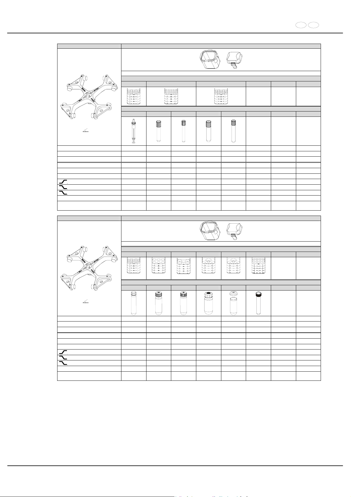
DE EN
71/104
5624 5625 + 5627
+
mit Bioabdichtung / with bio-containment 12)
Gestell / frame
4733 4732 4733
Röhrchen / tube
----
---- ---- ---- ----
Ausschwingrotor 4-fach /
Swing out rotor 4-times
90°
Kapazität / capacity ml 10 1,6 - 5 4 - 7 4 - 7 8,5 – 10
Maße / dimensions x L
mm 15 x 102 13 x 75 13 x 100 16 x 75 16 x 100
Anzahl p. Rotor / number p. rotor 68 80 80 68 68
Drehzahl / speed RPM 4600 4600 4600 4600 4600
RZB / RCF
3)
4637 4637 4637 4637 4637
Radius / radius mm 196 196 196 196 196
9 (97%)
sec 90 90 90 90 90
9
sec 95 95 95 95 95
0
sec 960 960 960 960 960
Temperatur / temperature °C 1) 4 4 4 4 4
Probenerwärmung/Sample
temp. rise
K2) 19 19 19 19 19
5624 5625 + 5627
+
mit Bioabdichtung / with bio-containment 12)
Gestell / frame
4733 4734 4740 11) 4736 4736 4739 11)
1
Röhrchen / tube
---- 0545 0546 0547 0539 / 0538 ----
Ausschwingrotor 4-fach /
Swing out rotor 4-times
90°
Kapazität / capacity ml 10 30 50 85 94 14
Maße / dimensions x L
mm 16 x 80 26 x 95 29 x 107 38 x 106 38 x 110,5 16,5 x 10⁶
Anzahl p. Rotor / number p. rotor 68 24 20 12 12 48
Drehzahl / speed RPM 4600 4600 4600 4600 4600 4600
RZB / RCF
3)
4637 4637 4637 4495 4495 4637
Radius / radius mm 196 196 196 190 190 196
9 (97%)
sec 90 90 90 90 90 90
9
sec 95 95 95 95 95 95
0
sec 960 960 960 960 960 960
Temperatur / temperature °C 1) 4 4 4 4 4 4
Probenerwärmung/Sample
temp. rise
K2) 19 19 19 19 19 19
1) Niedrigste Probentemperatur bei Vorkühlung und maximaler
Drehzahl (nur bei Kühlzentrifuge)
1) Lowest sample temperature with pre-cooling and maximum speed (only
with cooling centrifuges)
2) Probenerwärmung bei maximaler Drehzahl und 1 Stunde
Laufzeit (nur bei Zentrifuge ohne Kühlung)
2) Sample temp. rise during maximum speed and 1 hour running time (only
with centrifuges without cooling)
3) Zentrifugiergefäße aus Glas nur belastbar bis RZB 4000 3) Centrifuge containers of glass will not stand RCF values exceeding 4000
11) Die Einlage aus den Gestellen entfernen 11) Take the inserts out of the frame / adapter
12) Nach DIN EN 61010, Teil 2 – 020. Die Hinweise für Bio-Sicher-
heitssysteme in den Kapiteln "Sicherheitshinweise" und "Pflege
und Wartung" beachten.
12) in conformity with DIN EN 61010, part 2 – 020. Observe the notes for bio
safety systems in chapters "Notes on safety" and "Maintenance and
servicing".
Page 72
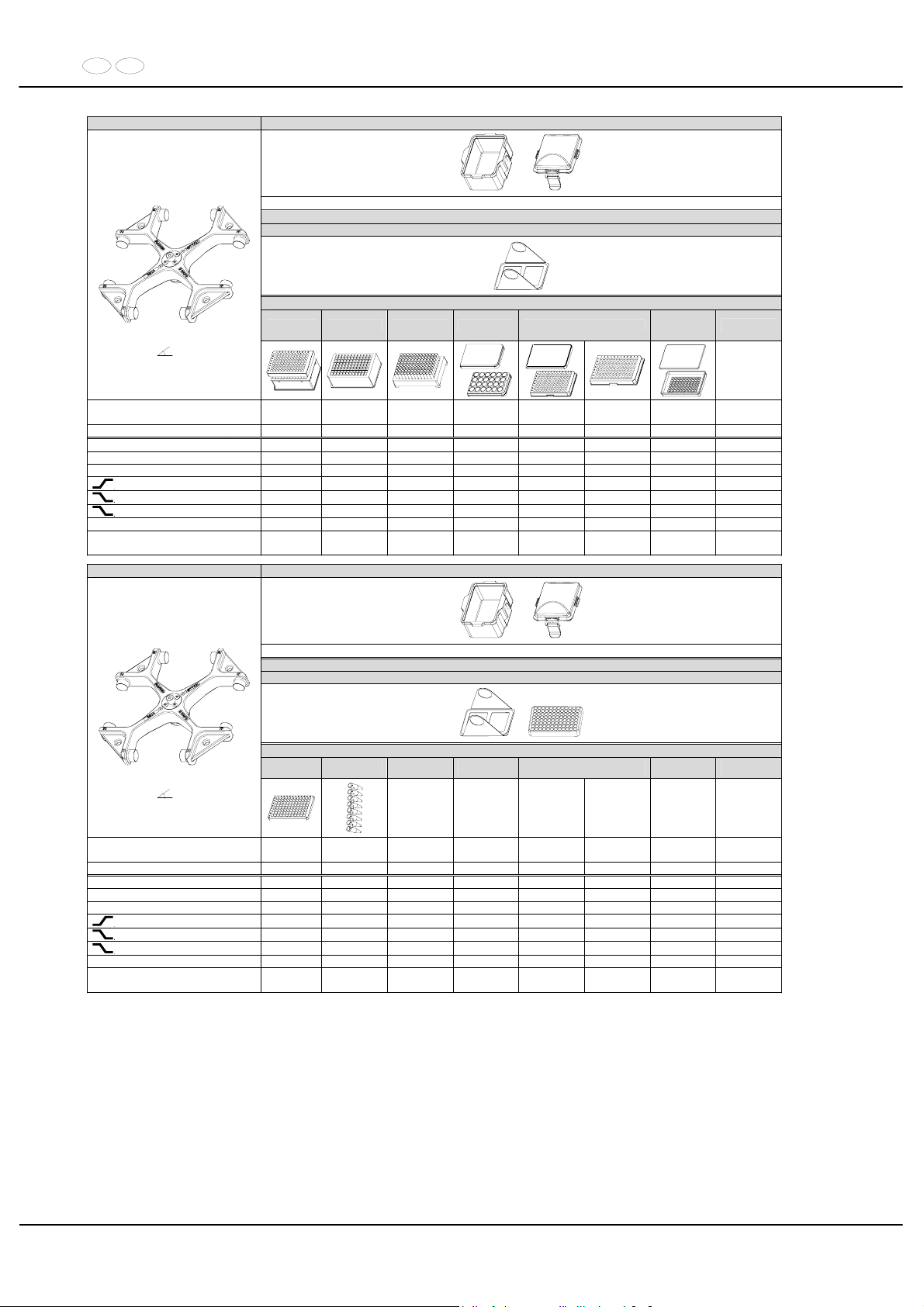
DE EN
72/104
5624 5628 + 5629
+
mit Bioabdichtung / with bio-containment 12)
Gestell / frame
4626
Platten / plates
QP DWP MS CP MTP
Microtest-
platten / plate
Terasaki
Ausschwingrotor 4-fach /
Swing out rotor 4-times
90°
Maße / dimensions
TxBxH / DxWxH
mm
86x128x 83 86x128x44,5 86x128x46 86x128x22 86x128x17,5 86x128x15 59x84x11
Anzahl p. Rotor / number p. rotor 4 4 4 16 20 24 8
Drehzahl / speed RPM 4600 4600 4600 4600 4600 4600 4600
RZB / RCF
3)
4211 4211 4211 4211 4211 4211 4211
Radius / radius mm 178 178 178 178 178 178 178
9 (97%)
sec 90 90 90 90 90 90 90
9
sec 95 95 95 95 95 95 95
0
sec 960 960 960 960 960 960 960
Temperatur / temperature °C 1) 4 4 4 4 4 4 4
Probenerwärmung/Sample
temp. rise
K
2)
18 18 18 18 18 18 18
5624 5628 + 5629
+
mit Bioabdichtung / with bio-containment 12)
Gestell / frame
4626 + 1469
+
Platten / plates
96-PCR-
Platte / plate
PCR-Strips
Ausschwingrotor 4-fach /
Swing out rotor 4-times
90°
Maße / dimensions
TxBxH / DxWxH
mm
82x124x20
Anzahl p. Rotor / number p. rotor 4 48 x 8
Drehzahl / speed RPM 4600 4600
RZB / RCF
3)
4211 4211
Radius / radius mm 178 178
9 (97%)
sec 90 90
9
sec 95 95
0
sec 960 960
Temperatur / temperature °C 1) 4 4
Probenerwärmung/Sample
temp. rise
K
2)
18 18
1) Niedrigste Probentemperatur bei Vorkühlung und maximaler
Drehzahl (nur bei Kühlzentrifuge)
1) Lowest sample temperature with pre-cooling and maximum speed (only
with cooling centrifuges)
2) Probenerwärmung bei maximaler Drehzahl und 1 Stunde
Laufzeit (nur bei Zentrifuge ohne Kühlung)
2) Sample temp. rise during maximum speed and 1 hour running time (only
with centrifuges without cooling)
3) Zentrifugiergefäße aus Glas nur belastbar bis RZB 4000 3) Centrifuge containers of glass will not stand RCF values exceeding 4000
12) Nach DIN EN 61010, Teil 2 – 020. Die Hinweise für Bio-Sicher-
heitssysteme in den Kapiteln "Sicherheitshinweise" und "Pflege
und Wartung" beachten.
12) in conformity with DIN EN 61010, part 2 – 020. Observe the notes for bio
safety systems in chapters "Notes on safety" and "Maintenance and
servicing".
MTP Mikrotiterplatte /
Microtitre plate
CP Kulturplatte /
Culture plate
DWP Deep Well Platte /
Deep well plate
MS Micronic System /
Micronic system
QP Filterplatte /
Filter plate
Page 73
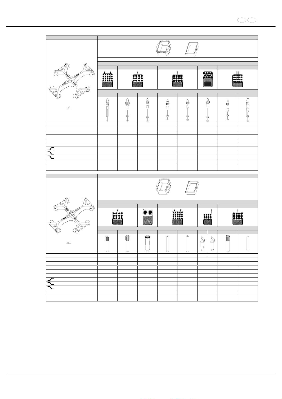
DE EN
73/104
5624 5628 + 5220-A
4) +
Gestell / frame
5267 5268 5264 5258 5227
---- ---- ---- ---- ---- ---- ---- ----
Ausschwingrotor 4-fach /
Swing out rotor 4-times
90°
Kapazität / capacity ml 1,1; 1,2; 1,4 2,6; 2,9 4,9 4 - 5,5 7,5-8,2 9 - 10 2,7 - 3 4,5 - 5
Maße / dimensions x L
mm 8 x 66 13 x 65 13 x 90 15 x 75 15 x 92 16 x 92 11 x 66 11 x 92
Anzahl p. Rotor / number p. rotor 160 96 96 96 96 88 160 160
Drehzahl / speed RPM 4600 4600 4600 4600 4600 4600 4600 4600
RZB / RCF
3)
4069 4164 4164 4116 4116 4093 4116 4116
Radius / radius mm 172 176 176 174 174 173 174 174
9 (97%)
sec 90 90 90 90 90 90 90 90
9
sec 95 95 95 95 95 95 95 95
0
sec 960 960 960 960 960 960 960 960
Temperatur / temperature °C 1) 4 4 4 4 4 4 4 4
Probenerwärmung/Sample
temp. rise
K
2)
18 18 18 18 18 18 18 18
5624 5628 + 5220-A
4) +
Gestell / frame
5268 5259 5267 5281 5264
Röhrchen / tube
---- ---- 0513 ---- ----
2078 0536
---- 0500
Ausschwingrotor 4-fach /
Swing out rotor 4-times
90°
Kapazität / capacity ml 1,6 - 5 4 - 7 50 4 3 1,5 2,0 4 - 7 9
Maße / dimensions x L
mm 13 x 75 13 x 100 30 x 115 10 x 88 10 x 60 11 x 38 16 x 75 14 x 100
Anzahl p. Rotor / number p. rotor 96 96 16 160 160 128 96 96
Drehzahl / speed RPM 4600 4600 4600 4600 4600 4600 4600 4600
RZB / RCF
3)
4164 4164 4187 4069 4069 4164 4116 4116
Radius / radius mm 176 176 177 160 172 176 174 174
9 (97%)
sec 90 90 90 90 90 90 90 90
9
sec 95 95 95 95 95 95 95 95
0
sec 960 960 960 960 960 960 960 960
Temperatur / temperature °C 1) 4 4 4 4 4 4 4 4
Probenerwärmung/Sample
temp. rise
K
2)
18 18 18 18 18 18 18 18
1) Niedrigste Probentemperatur bei Vorkühlung und maximaler
Drehzahl (nur bei Kühlzentrifuge)
1) Lowest sample temperature with pre-cooling and maximum speed (only
with cooling centrifuges)
2) Probenerwärmung bei maximaler Drehzahl und 1 Stunde
Laufzeit (nur bei Zentrifuge ohne Kühlung)
2) Sample temp. rise during maximum speed and 1 hour running time (only
with centrifuges without cooling)
3) Zentrifugiergefäße aus Glas nur belastbar bis RZB 4000 3) Centrifuge containers of glass will not stand RCF values exceeding 4000
4) nicht mit Deckel 5629 verschließbar 4) not closeable with lid 5629
Page 74
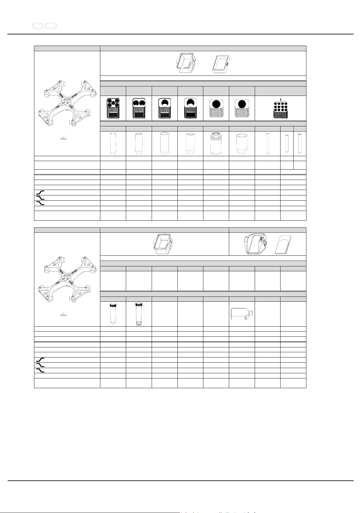
DE EN
74/104
5624 5628 + 5220-A
4) +
Gestell / frame
5242 5243 5249 5262
5263-A +
6319 11)
5263-A 5268
Röhrchen / tube
0519 0521 0523 0526 5127 0530 0578
0553 0501
Ausschwingrotor 4-fach /
Swing out rotor 4-times
90°
Kapazität / capacity ml 25 50 100 100 250 250 7 5 6
Maße / dimensions x L
mm 24 x 100 34 x 100 40 x 115 44 x 100 62 x 122 65 x 115 12 x 100
12 x 7512 x
82
Anzahl p. Rotor / number p. rotor 40 16 8 8 4 4 96 96
Drehzahl / speed RPM 4600 4600 4600 4600 4600 4600 4600 4600
RZB / RCF
3)
4093 4093 4069 4069 4187 4045 4164 4164
Radius / radius mm 173 173 172 172 177 171 176 176
9 (97%)
sec 90 90 90 90 90 90 90 90
9
sec 95 95 95 95 95 95 95 95
0
sec 960 960 960 960 960 960 960 960
Temperatur / temperature °C 1) 4 4 4 4 4 4 4 4
Probenerwärmung/Sample
temp. rise
K
2)
18 18 18 18 18 18 18 18
5624 5628 5630
4)
Gestell / frame
6338-A 6339-A
0513 ----
Ausschwingrotor 4-fach /
Swing out rotor 4-times
90°
Kapazität / capacity ml 50 50 200
Maße / dimensions x L
mm 29 x 115 29 x 115
146x79x36,5
Anzahl p. Rotor / number p. rotor 24 24 4
Drehzahl / speed RPM 4600 4600 4600
RZB / RCF
3)
4258 4187 3738
Radius / radius mm 180 177 158
9 (97%)
sec 90 90 90
9
sec 95 95 95
0
sec 960 960 960
Temperatur / temperature °C 1) 4 4 4
Probenerwärmung/Sample
temp. rise
K
2)
18 18 18
1) Niedrigste Probentemperatur bei Vorkühlung und maximaler
Drehzahl (nur bei Kühlzentrifuge)
1) Lowest sample temperature with pre-cooling and maximum speed (only
with cooling centrifuges)
2) Probenerwärmung bei maximaler Drehzahl und 1 Stunde
Laufzeit (nur bei Zentrifuge ohne Kühlung)
2) Sample temp. rise during maximum speed and 1 hour running time (only
with centrifuges without cooling)
3) Zentrifugiergefäße aus Glas nur belastbar bis RZB 4000 3) Centrifuge containers of glass will not stand RCF values exceeding 4000
4) nicht mit Deckel 5629 verschließbar 4) not closeable with lid 5629
11) Die Einlage aus den Gestellen entfernen 11) Take the inserts out of the frame / adapter
Page 75
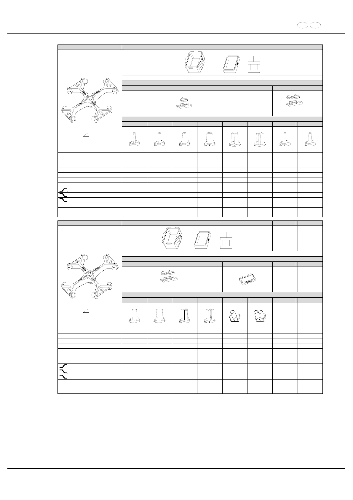
DE EN
75/104
5624 5628 + 5220-A + 5280
4) + +
Spannplatte / slide carrier
1662 1670
2 x in 5280
6)
2 x in 5280
Zyto-Kammer / cyto chamber
1663 1664 1665 1666 1667 1668 1663 1664
Ausschwingrotor4-fach /
Swing out rotor 4-times
90°
Kapazität / capacity ml 1 2 4 8 3 x 2 4 x 1 1 2
Maße / dimensions / A
mm² 6,2 / 30 8,7 / 60 12,4 / 120 17,5 / 240 8,7 / 60 6,2 / 30 6,2 / 30 8,7 x 60
Anzahl p. Rotor / number p. rotor 8 8 8 8 8 8 16 16
Filterkarten / filter cards 1675 1675 1675 1676 1677 1678 1692 1692
Drehzahl / speed RPM 4600 4600 4600 4600 4600 4600 4600 4600
RZB / RCF 2744/4069 2744/4069 2744/4069 2744/4069 2744/4069 2744/4069 2744/4069 2744/4069
Radius / radius mm 116 / 172 116 / 172 116 / 172 116 / 172 116 / 172 116 / 172 116 / 172 116 / 172
9 (97%)
sec 90 90 90 90 90 90 90 90
9
sec 95 95 95 95 95 95 95 95
0
sec 960 960 960 960 960 960 960 960
Temperatur / temperature °C 1) 4 4 4 4 4 4 4 4
Probenerwärmung/Sample
temp. rise
K2) 18 18 18 18 18 18 18 18
5624 5628 + 5220-A + 5280
4) + +
Spannplatte / slide carrier
1670 1470
6)
2 x in 5280
Zyto-Kammer / cyto chamber
1665 1666 1667 1668 1471 1475
Ausschwingrotor 4-fach /
Swing out rotor 4-times
90°
Kapazität / capacity ml 4 8 3 x 2 4 x 1 1 x 8 2 x 8
Maße / dimensions / A
mm² 12,4 x 120 17,5 x 240 8,7 / 60 6,2 / 30 17,5 / 240 17,5 / 240
Anzahl p. Rotor / number p. rotor 16 16 16 16 8 8
Filterkarten / filter cards 1692 1691 1694 1693 --- ---
Drehzahl / speed RPM 4600 4600 4600 4600 4600 4600
RZB / RCF 2744/4069 2744/4069 2744/4069 2744/4069 2626/3951 2626/3951
Radius / radius mm 116 / 172 116 / 172 116 / 172 116 / 172 111 / 167 111 / 167
9 (97%)
sec 90 90 90 90 90 90
9
sec 95 95 95 95 95 95
0
sec 960 960 960 960 960 960
Temperatur / temperature °C 1) 4 4 4 4 4 4
Probenerwärmung/Sample
temp. rise
K2) 18 18 18 18 18 18
1) Niedrigste Probentemperatur bei Vorkühlung und maximaler
Drehzahl (nur bei Kühlzentrifuge)
1) Lowest sample temperature with pre-cooling and maximum speed
(only with cooling centrifuges)
2) Probenerwärmung bei maximaler Drehzahl und
1 Stunde Laufzeit (nur bei Zentrifuge ohne Kühlung)
2) Sample temp. rise during maximum speed and 1 hour
running time (only with centrifuges without cooling)
4) nicht mit Deckel 5629 verschließbar 4) not closeable with lid 5629
6) Objektträger nur belastbar bis RZB 1100 6) Object slide will not stand RCF values exceeding 1100
Page 76
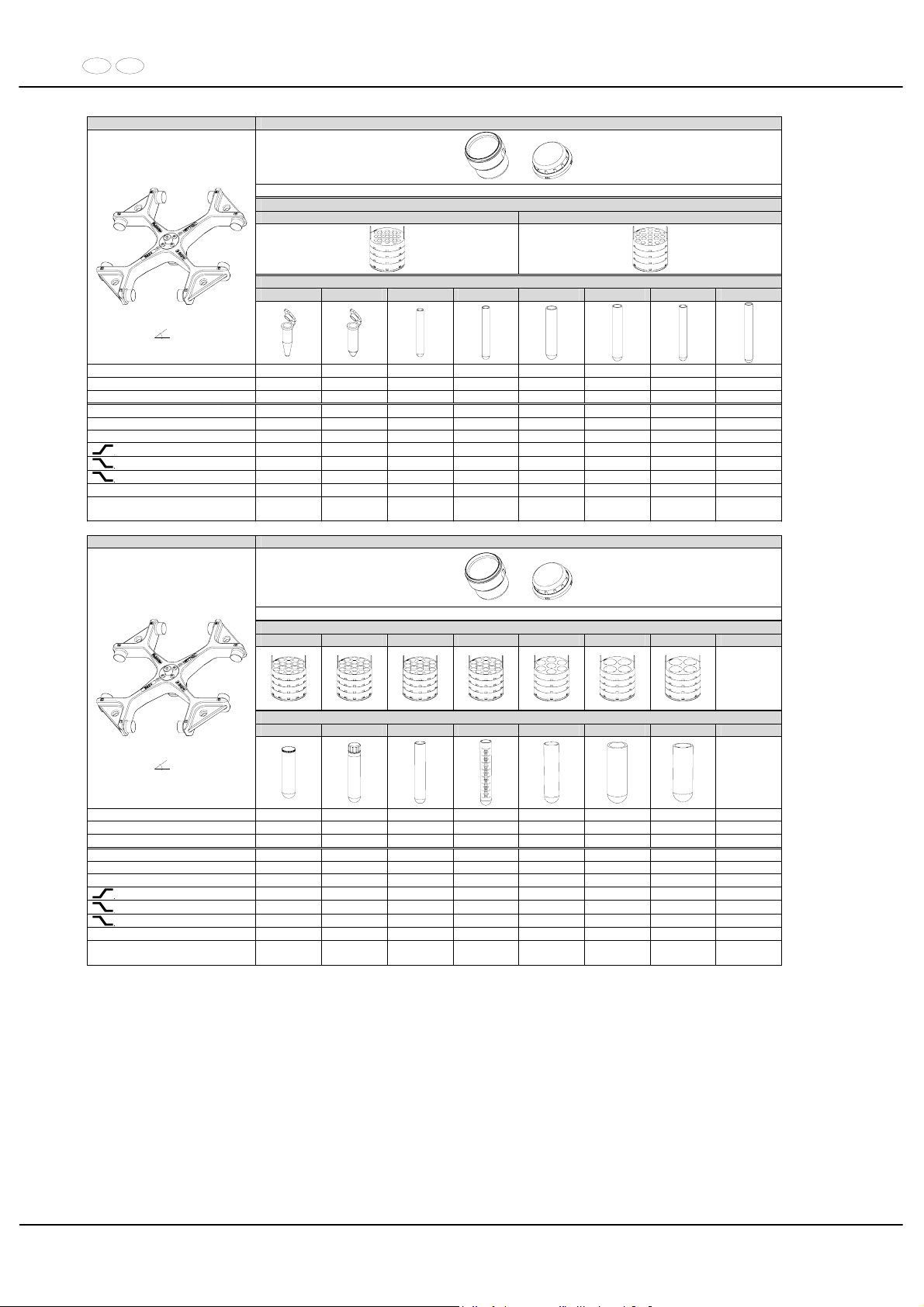
DE EN
76/104
5624 5620 + 5621
+
mit Bioabdichtung / with bio-containment 12)
Reduzierung / adapter
4830 4832
Röhrchen / tube
2078 0536 ---- ---- ---- 0553 0501 0578
Ausschwingrotor 4-fach /
Swing out rotor 4-times
90°
Kapazität / capacity ml 1,5 2,0 3 4 4 5 6 7
Maße / dimensions x L
mm 11 x 38 11 x 38 10 x 60 10 x 88 12 x 60 12 x 75 12 x 82 12 x 100
Anzahl p. Rotor / number p. rotor 192 192 96 96 76 76 76 76
Drehzahl / speed RPM 4600 4600 4600 4600 4600 4600 4600 4600
RZB / RCF
3)
3572/4637 3572/4637 4637 4637 4637 4637 4637 4637
Radius / radius mm 151/196 151/196 196 196 196 196 196 196
9 (97%)
sec 90 90 90 90 90 90 90 90
9
sec 95 95 95 95 95 95 95 95
0
sec 960 960 960 960 960 960 960 960
Temperatur / temperature °C 1) 4 4 4 4 4 4 4 4
Probenerwärmung/Sample
temp. rise
K2) 18 18 18 18 18 18 18 18
5624 5620 + 5621
+
mit Bioabdichtung / with bio-containment 12)
Reduzierung / adapter
4833 4833 4833 4833 4834 4835 4835
Röhrchen / tube
2079 ---- 0507 0518 0519 ---- 0521
Ausschwingrotor 4-fach /
Swing out rotor 4-times
90°
Kapazität / capacity ml 10 10 15 15 25 45 50
Maße / dimensions x L
mm 17 x 70 16 x 80 17 x 100 17 x 100 24 x 100 31 x 100 34 x 100
Anzahl p. Rotor / number p. rotor 76 76 76 76 28 16 16
Drehzahl / speed RPM 4600 4600 4600 4600 4600 4600 4600
RZB / RCF
3)
4637 4637 4637 4637 4637 4495 4495
Radius / radius mm 196 196 196 196 196 190 190
9 (97%)
sec 90 90 90 90 90 90 90
9
sec 95 95 95 95 95 95 95
0
sec 960 960 960 960 960 960 960
Temperatur / temperature °C 1) 4 4 4 4 4 4 4
Probenerwärmung/Sample
temp. rise
K2) 18 18 18 18 18 18 18
1) Niedrigste Probentemperatur bei Vorkühlung und maximaler
Drehzahl (nur bei Kühlzentrifuge)
1) Lowest sample temperature with pre-cooling and maximum speed (only
with cooling centrifuges)
2) Probenerwärmung bei maximaler Drehzahl und 1 Stunde
Laufzeit (nur bei Zentrifuge ohne Kühlung)
2) Sample temp. rise during maximum speed and 1 hour running time (only
with centrifuges without cooling)
3) Zentrifugiergefäße aus Glas nur belastbar bis RZB 4000 3) Centrifuge containers of glass will not stand RCF values exceeding 4000
12) Nach DIN EN 61010, Teil 2 – 020. Die Hinweise für Bio-Sicher-
heitssysteme in den Kapiteln "Sicherheitshinweise" und "Pflege
und Wartung" beachten.
12) in conformity with DIN EN 61010, part 2 – 020. Observe the notes for bio
safety systems in chapters "Notes on safety" and "Maintenance and
servicing".
Page 77
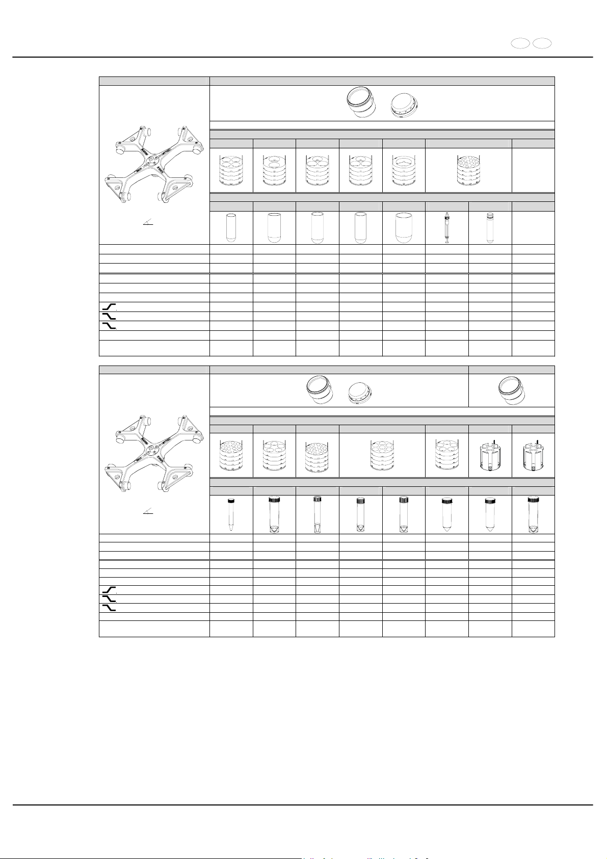
DE EN
77/104
5624 5620 + 5621
+
mit Bioabdichtung / with bio-containment 12)
Reduzierung / adapter
4835 4837 4836 4836 4838 4839 11)
Röhrchen / tube
0548 0526 0549 0523 0530
---- ----
Ausschwingrotor 4-fach /
Swing out rotor 4-times
90°
Kapazität / capacity ml 75 100 85 100 250 10 14
Maße / dimensions x L
mm 35 x 105 44 x 100 38 x 106 40 x 115 65 x 115 15 x 102 16,5 x 10⁶
Anzahl p. Rotor / number p. rotor 16 8 12 12 4 56 56
Drehzahl / speed RPM 4600 4600 4600 4600 4600 4600 4600
RZB / RCF
3)
4495 4637 4495 4495 4495 4637 4637
Radius / radius mm 190 196 190 190 190 196 196
9 (97%)
sec 90 90 90 90 90 90 90
9
sec 95 95 95 95 95 95 95
0
sec 960 960 960 960 960 960 960
Temperatur / temperature °C 1) 4 4 4 4 4 4 4
Probenerwärmung/Sample
temp. rise
K2) 18 18 18 18 18 18 18
5624 5620 + 5621 5620
+
mit Bioabdichtung / with bio-containment 12)
Reduzierung / adapter
4839 4840 11) 4839 11) 4834 4840 5647 5647 11)
)
Röhrchen / tube
0509 ---- ---- ---- ---- 0513 0513 ----
Ausschwingrotor 4-fach /
Swing out rotor 4-times
90°
Kapazität / capacity ml 15 50 12 25 30 50 50 50
Maße / dimensions x L
mm 17 x 120 30 x 115 17 x 100 25 x 90 25 x 110 29 x 115 30 x 115 30 x 115
Anzahl p. Rotor / number p. rotor 56 20 56 28 28 20 28 28
Drehzahl / speed RPM 4600 4600 4600 4600 4600 4600 4600 4600
RZB / RCF
3)
4637 4637 4637 4637 4637 4637 4708 4708
Radius / radius mm 196 196 196 196 196 196 199 199
9 (97%)
sec 90 90 90 90 90 90 90 90
9
sec 95 95 95 95 95 95 95 95
0
sec 960 960 960 960 960 960 960 960
Temperatur / temperature °C 1) 4 4 4 4 4 4 4 4
Probenerwärmung/Sample
temp. rise
K2) 18 18 18 18 18 18 18 18
1) Niedrigste Probentemperatur bei Vorkühlung und maximaler
Drehzahl (nur bei Kühlzentrifuge)
1) Lowest sample temperature with pre-cooling and maximum speed (only
with cooling centrifuges)
2) Probenerwärmung bei maximaler Drehzahl und 1 Stunde
Laufzeit (nur bei Zentrifuge ohne Kühlung)
2) Sample temp. rise during maximum speed and 1 hour running time (only
with centrifuges without cooling)
3) Zentrifugiergefäße aus Glas nur belastbar bis RZB 4000 3) Centrifuge containers of glass will not stand RCF values exceeding 4000
11) Die Einlagen aus den Gestellen / Reduzierungen entfernen 11) Take the inserts out of the frames / adapters
12) Nach DIN EN 61010, Teil 2 – 020. Die Hinweise für Bio-Sicher-
heitssysteme in den Kapiteln "Sicherheitshinweise" und "Pflege
und Wartung" beachten.
12) in conformity with DIN EN 61010, part 2 – 020. Observe the notes for bio
safety systems in chapters "Notes on safety" and "Maintenance and
servicing".
Page 78
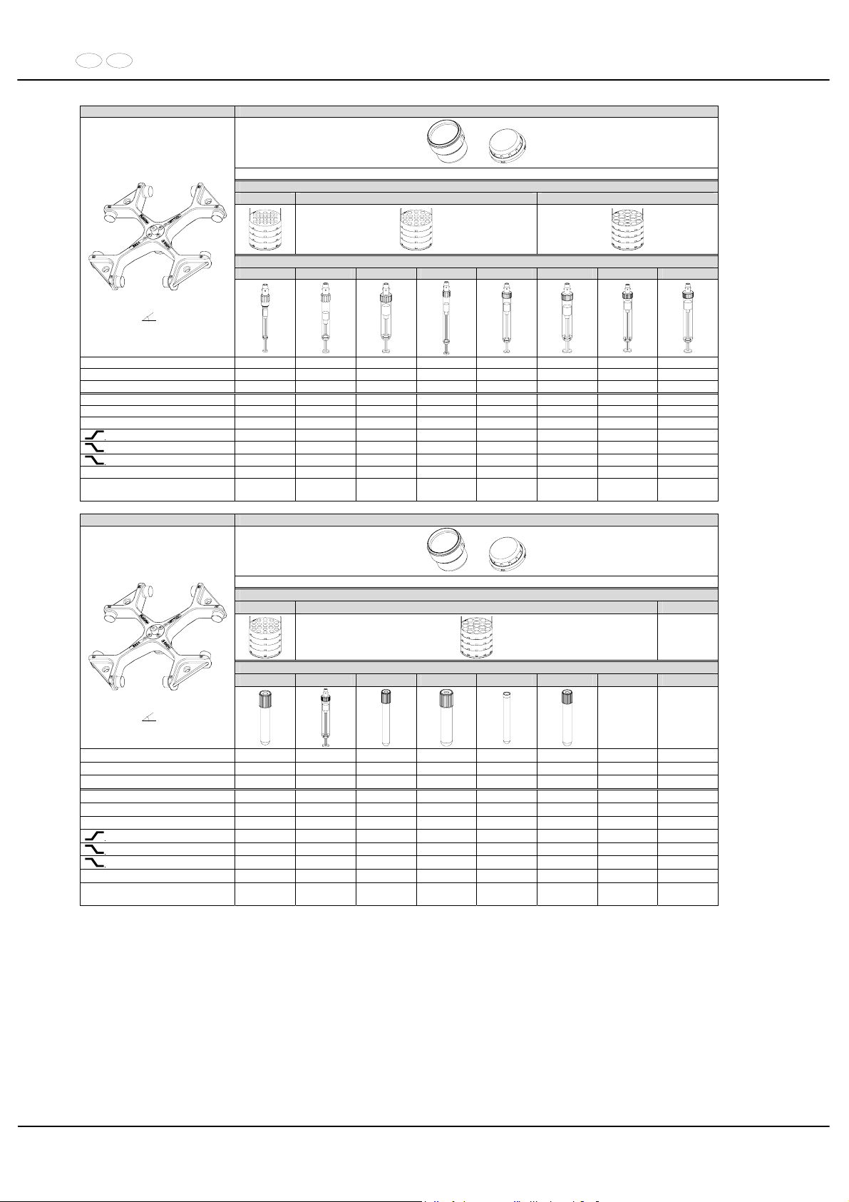
DE EN
78/104
5624 5620 + 5621
+
mit Bioabdichtung / with bio-containment 12)
Reduzierung / adapter
4830 4832 4833
Röhrchen / tube
---- ---- ---- ---- ---- ---- ---- ----
Ausschwingrotor 4-fach /
Swing out rotor 4-times
90°
Kapazität / capacity ml 1,1; 1,2; 1,4 2,7 - 3 2,6; 2,9 4,5 - 5 4,9 4 - 5,5 7,5 - 8,2 9 - 10
Maße / dimensions x L
mm 8 x 66 11 x 66 13 x 65 11 x 92 13 x 90 15 x 75 15 x 92 16 x 92
Anzahl p. Rotor / number p. rotor 96 76 76 76 76 76 76 76
Drehzahl / speed RPM 4600 4600 4600 4600 4600 4600 4600 4600
RZB / RCF
3)
4637 4637 4637 4637 4637 4637 4637 4637
Radius / radius mm 196 196 196 196 196 196 191 191
9 (97%)
sec 90 90 90 90 90 90 90 90
9
sec 95 95 95 95 95 95 95 95
0
sec 960 960 960 960 960 960 960 960
Temperatur / temperature °C 1) 4 4 4 4 4 4 4 4
Probenerwärmung/Sample
temp. rise
K2) 18 18 18 18 18 18 18 18
5624 5620 + 5621
+
mit Bioabdichtung / with bio-containment 12)
Reduzierung / adapter
4832 4833
Röhrchen / tube
---- ---- ---- ---- ---- ----
Ausschwingrotor 4-fach /
Swing out rotor 4-times
90°
Kapazität / capacity ml 1,6 - 5 10 4 - 7 4 - 7 8 8,5 - 10
Maße / dimensions x L
mm 13 x 75 15 x 102 13 x 100 16 x 75 16 x 125 16 x 100
Anzahl p. Rotor / number p. rotor 76 76 76 76 76 76
Drehzahl / speed RPM 4600 4600 4600 4600 4600 4600
RZB / RCF
3)
4637 4637 4637 4637 4637 4637
Radius / radius mm 196 196 196 196 196 196
9 (97%)
sec 90 90 90 90 90 90
9
sec 95 95 95 95 95 95
0
sec 960 960 960 960 960 960
Temperatur / temperature °C 1) 4 4 4 4 4 4
Probenerwärmung/Sample
temp. rise
K
2)
18 18 18 18 18 18
1) Niedrigste Probentemperatur bei Vorkühlung und maximaler
Drehzahl (nur bei Kühlzentrifuge)
1) Lowest sample temperature with pre-cooling and maximum speed (only
with cooling centrifuges)
2) Probenerwärmung bei maximaler Drehzahl und 1 Stunde
Laufzeit (nur bei Zentrifuge ohne Kühlung)
2) Sample temp. rise during maximum speed and 1 hour running time (only
with centrifuges without cooling)
3) Zentrifugiergefäße aus Glas nur belastbar bis RZB 4000 3) Centrifuge containers of glass will not stand RCF values exceeding 4000
12) Nach DIN EN 61010, Teil 2 – 020. Die Hinweise für Bio-Sicherheitssysteme in den Kapiteln "Sicherheitshinweise" und "Pflege
und Wartung" beachten.
12) In conformity with DIN EN 61010, part 2 – 020. Observe the notes for
bio safety systems in chapters "Notes on safety" and "Maintenance and
servicing".
Page 79
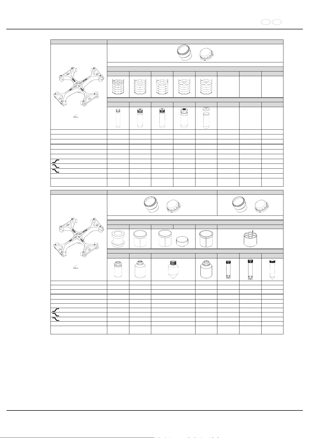
DE EN
79/104
5624 5620 + 5621
+
mit Bioabdichtung / with bio-containment 12)
Reduzierung / adapter
4833 4834 4840 11) 4836 4836
Röhrchen / tube
Nalgene
®
0545 0546 0547 0539 / 0538
Ausschwingrotor 4-fach /
Swing out rotor 4-times
90°
Kapazität / capacity ml 10 30 50 85 94
Maße / dimensions x L
mm 16 x 80 26 x 95 29 x 107 38 x 106 38 x 110,5
Anzahl p. Rotor / number p. rotor 76 28 20 12 12
Drehzahl / speed RPM 4600 4600 4600 4600 4600
RZB / RCF
3)
4637 4637 4637 4495 4495
Radius / radius mm 196 196 196 190 190
9 (97%)
sec 90 90 90 90 90
9
sec 95 95 95 95 95
0
sec 960 960 960 960 960
Temperatur / temperature °C 1) 4 4 4 4 4
Probenerwärmung/Sample
temp. rise
K
2)
18 18 18 18 18
5624 5620 + 5621 5623 + 5621
+
+
mit Bioabdichtung / with bio-containment 12)
Reduzierung / adapter
4841 4845 4845 4449 4846 4438
+
Flasche / bottle
5127 0512 4) Corning 0551
Ausschwingrotor 4-fach /
Swing out rotor 4-times
90°
Kapazität / capacity ml 250 750 500 600 25 30 30
Maße / dimensions x L
mm 62 x 122 97 x 152 96 x 147 93 x 134 25 x 90 25 x 110 25 x 110
Anzahl p. Rotor / number p. rotor 4 4 4 4 28 28 28
Drehzahl / speed RPM 4600 4600 4600 4600 4600 4600 4600
RZB / RCF
3)
4779 4779 4779 4779 4566 4566 4566
Radius / radius mm 202 202 202 202 193 193 193
9 (97%)
sec 90 90 90 90 90 90 90
9
sec 95 95 95 95 95 95 95
0
sec 960 960 960 960 960 960 960
Temperatur / temperature °C 1) 4 4 4 4 4 4 4
Probenerwärmung/Sample
temp. rise
K2) 18 18 18 18 18 18 18
1) Niedrigste Probentemperatur bei Vorkühlung und maximaler
Drehzahl (nur bei Kühlzentrifuge)
1) Lowest sample temperature with pre-cooling and maximum speed (only
with cooling centrifuges)
2) Probenerwärmung bei maximaler Drehzahl und 1 Stunde
Laufzeit (nur bei Zentrifuge ohne Kühlung)
2) Sample temp. rise during maximum speed and 1 hour running time (only
with centrifuges without cooling)
3) Zentrifugiergefäße aus Glas nur belastbar bis RZB 4000 3) Centrifuge containers of glass will not stand RCF values exceeding 4000
4) nicht mit Deckel 5629 verschließbar 4) not closeable with lid 5629
11) Die Einlage aus den Gestellen entfernen 11) Take the inserts out of the frame / adapter
12) Nach DIN EN 61010, Teil 2 – 020. Die Hinweise für Bio-Sicher-
heitssysteme in den Kapiteln "Sicherheitshinweise" und "Pflege
und Wartung" beachten.
12) In conformity with DIN EN 61010, part 2 – 020. Observe the notes for bio
safety systems in chapters "Notes on safety" and "Maintenance and
servicing".
Page 80
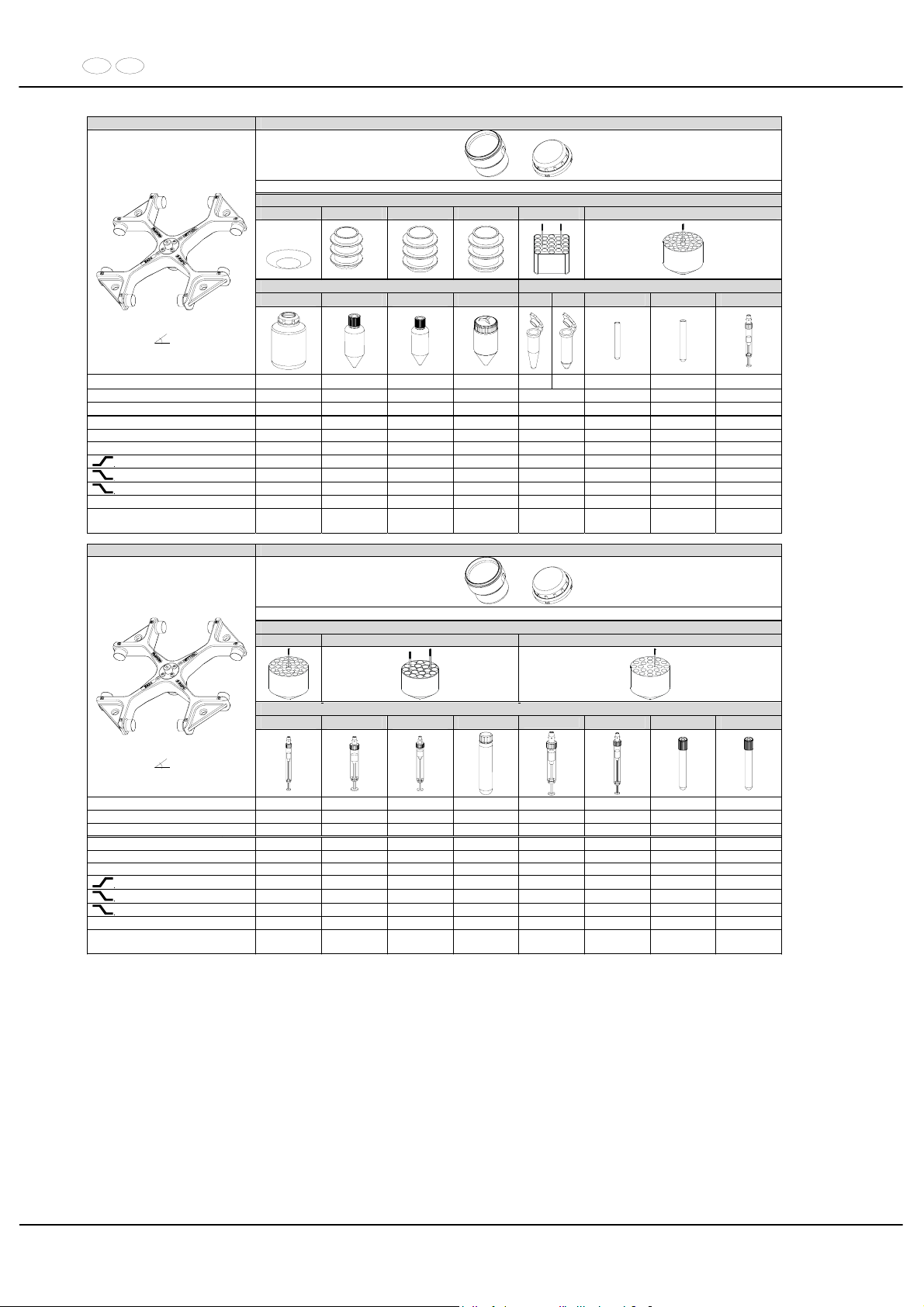
DE EN
80/104
5624 5623 + 5621
+
mit Bioabdichtung / with bio-containment 12)
Reduzierung / adapter
4451 4) 4430 4430 4430 4432 4433
4)
Flasche / bottle Röhrchen / tube
0512 Corning Nunc
®
Nalgene
®
2078 0536
0553 0578
Ausschwingrotor 4-fach /
Swing out rotor 4-times
90°
Kapazität / capacity ml 750 250 200 175 1,5 2,0 5
7
2,7 - 3
Maße / dimensions x L
mm 97 x 152 60 x 172 60 x 130 62 x 144 11 x 38 12 x 75 12 x 100 11 x 66
Anzahl p. Rotor / number p. rotor 4 4 4 4 168 120 120 120
Drehzahl / speed RPM 4600 4600 4600 4600 4600 4600 4600 4600
RZB / RCF
3)
4873 5063 5063 5063 3407/4542 4471 4471 4471
Radius / radius mm 206 214 214 214 144/192 189 189 189
9 (97%)
sec 90 90 90 90 90 90 90 90
9
sec 95 95 95 95 95 95 95 95
0
sec 960 960 960 960 960 960 960 960
Temperatur / temperature °C 1) 4 4 4 4 4 4 4 4
Probenerwärmung/Sample
temp. rise
K2) 18 18 18 18 18 18 18 18
5624 5623 + 5621
+
mit Bioabdichtung / with bio-containment 12)
Reduzierung / adapter
4433 4434 4435
Röhrchen / tube
Nalgene
®
Ausschwingrotor 4-fach /
Swing out rotor 4-times
90°
Kapazität / capacity ml 4,5 - 5 4 – 5,5 9 - 10 10 2,6 – 2,9 4,9 1,6 - 5 4 - 7
Maße / dimensions x L
mm 11 x 92 15 x 75 16 x 92 16 x 80 13 x 65 13 x 90 13 x 75 13 x 100
Anzahl p. Rotor / number p. rotor 120 76 76 76 84 84 84 84
Drehzahl / speed RPM 4600 4600 4600 4600 4600 4600 4600 4600
RZB / RCF
3)
4471 4637 4637 4637 4471 4471 4471 4471
Radius / radius mm 189 196 196 196 189 189 189 189
9 (97%)
sec 90 90 90 90 90 90 90 90
9
sec 95 95 95 95 95 95 95 95
0
sec 960 960 960 960 960 960 960 960
Temperatur / temperature °C 1) 4 4 4 4 4 4 4 4
Probenerwärmung/Sample
temp. rise
K
2)
18 18 18 18 18 18 18 18
1) Niedrigste Probentemperatur bei Vorkühlung und maximaler
Drehzahl (nur bei Kühlzentrifuge)
1) Lowest sample temperature with pre-cooling and maximum speed (only
with cooling centrifuges)
2) Probenerwärmung bei maximaler Drehzahl und 1 Stunde
Laufzeit (nur bei Zentrifuge ohne Kühlung)
2) Sample temp. rise during maximum speed and 1 hour running time (only
with centrifuges without cooling)
3) Zentrifugiergefäße aus Glas nur belastbar bis RZB 4000 3) Centrifuge containers of glass will not stand RCF values exceeding 4000
4) nicht mit Deckel 5621 verschließbar 4) not closeable with lid 5621
12) Nach DIN EN 61010, Teil 2 – 020. Die Hinweise für Bio-Sicherheitssysteme in den Kapiteln "Sicherheitshinweise" und "Pflege
und Wartung" beachten.
12) In conformity with DIN EN 61010, part 2 – 020. Observe the notes for
bio safety systems in chapters "Notes on safety" and "Maintenance and
servicing".
Page 81
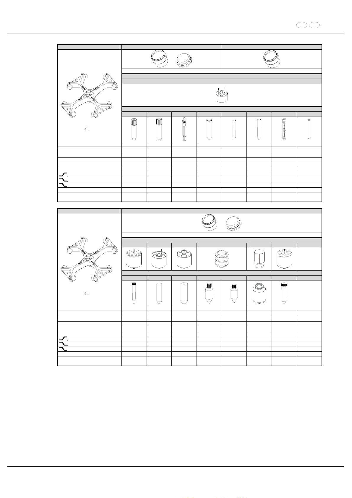
DE EN
81/104
5624 5623 + 5621 5623
+
mit Bioabdichtung / with bio-containment 12)
Reduzierung / adapter
4434
Röhrchen / tube
---- ---- ---- 0507 2079 0500 0518 ----
Ausschwingrotor 4-fach /
Swing out rotor 4-times
90°
Kapazität / capacity ml 4 -7 8,5 - 10 10 15 10 9 15 8
Maße / dimensions x L
mm 16 x 75 16 x 100 15 x 102 17 x 100 17 x 70 14 x 100 17 x 100 16 x 81
Anzahl p. Rotor / number p. rotor 76 76 76 76 76 76 76 76
Drehzahl / speed RPM 4600 4600 4600 4600 4600 4600 4600 4600
RZB / RCF
3)
4637 4637 4637 4637 4637 4637 4637 4637
Radius / radius mm 196 196 196 196 196 196 196 196
9 (97%)
sec 90 90 90 90 90 90 90 90
9
sec 95 95 95 95 95 95 95 95
0
sec 960 960 960 960 960 960 960 960
Temperatur / temperature °C 1) 4 4 4 4 4 4 4 4
Probenerwärmung/Sample
temp. rise
K2) 18 18 18 18 18 18 18 18
5624 5623 + 5621
+
mit Bioabdichtung / with bio-containment 12)
Reduzierung / adapter
4437
4438 + 0726
4439 4440 4466+4451 4441
Röhrchen / tube
0509 0519 0521 Falcon
®
0551 0513
Ausschwingrotor 4-fach /
Swing out rotor 4-times
90°
Kapazität / capacity ml 15 25 50 225 175 600 50
Maße / dimensions x L
mm 17 x 120 24 x 100 34 x 100 61 x 137 61 x 118 93 x 134 29 x 115
Anzahl p. Rotor / number p. rotor 48 28 16 4 4 20
Drehzahl / speed RPM 4600 4600 4600 4600 4600 4600 4600
RZB / RCF
3)
4755 4353 4424 5063 5063 4873 4755
Radius / radius mm 201 184 187 214 214 206 201
9 (97%)
sec 90 90 90 90 90 90 90
9
sec 95 95 95 95 95 95 95
0
sec 960 960 960 960 960 960 960
Temperatur / temperature °C 1) 4 4 4 4 4 4 4
Probenerwärmung/Sample
temp. rise
K
2)
18 18 18 18 18 18 18
1) Niedrigste Probentemperatur bei Vorkühlung und maximaler
Drehzahl (nur bei Kühlzentrifuge)
1) Lowest sample temperature with pre-cooling and maximum speed (only
with cooling centrifuges)
2) Probenerwärmung bei maximaler Drehzahl und 1 Stunde
Laufzeit (nur bei Zentrifuge ohne Kühlung)
2) Sample temp. rise during maximum speed and 1 hour running time (only
with centrifuges without cooling)
3) Zentrifugiergefäße aus Glas nur belastbar bis RZB 4000 3) Centrifuge containers of glass will not stand RCF values exceeding 4000
12) Nach DIN EN 61010, Teil 2 – 020. Die Hinweise für Bio-Sicherheitssysteme in den Kapiteln "Sicherheitshinweise" und "Pflege
und Wartung" beachten.
12) In conformity with DIN EN 61010, part 2 – 020. Observe the notes for
bio safety systems in chapters "Notes on safety" and "Maintenance and
servicing".
Page 82
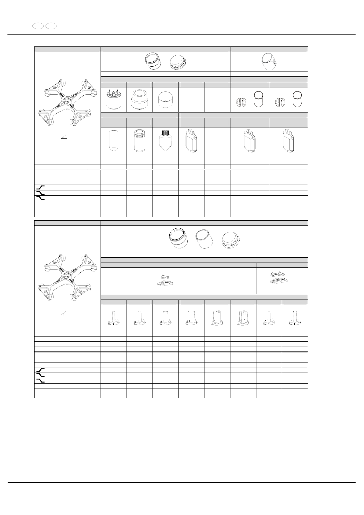
DE EN
82/104
5624 5623 + 5621 5691
+
mit Bioabdichtung / with bio-containment 12)
Reduzierung / adapter
4442 4443 4449 5693 + 5692 5695 + 5692
+ +
Röhrchen / tube Blutbeutelsystem / Blood bag system 5)
0526 5127 Corning
3-fach /
3-times
3-fach /
3-times
4-fach /
4-times
Ausschwingrotor 4-fach /
Swing out rotor 4-times
90°
Kapazität / capacity ml 100 250 500 450 450 450
Maße / dimensions x L
mm 44 x 100 62 x 122 96 x 147 --- --- --Anzahl p. Rotor / number p. rotor 8 4 4 4 4 4
Drehzahl / speed RPM 4600 4600 4600 4600 4600 4600
RZB / RCF
3)
4400 4873 5063 5063 4637 4637
Radius / radius mm 186 206 214 214 196 196
9 (97%)
sec 90 90 90 90 90 90
9
sec 95 95 95 95 95 95
0
sec 960 960 960 960 960 960
Temperatur / temperature °C 1) 4 4 4 4
11
10)
11
10)
Probenerwärmung/Sample
temp. rise
K
2)
18 18 18 18 16 16
5624 5620 + 4844 + 5280
+ +
Spannplatte / slide carrier
1662 1670
2 x in 5280
6)
2 x in 5280
Zyto-Kammer / cyto chamber
1663 1664 1665 1666 1667 1668 1663 1664
Ausschwingrotor4-fach /
Swing out rotor 4-times
90°
Kapazität / capacity ml 1 2 4 8 3 x 2 4 x 1 1 2
Maße / dimensions / A
mm² 6,2 / 30 8,7 / 60 12,4 / 120 17,5 / 240 8,7 / 60 6,2 / 30 6,2 / 30 8,7 x 60
Anzahl p. Rotor / number p. rotor 8 8 8 8 8 8 16 16
Filterkarten / filter cards 1675 1675 1675 1676 1677 1678 1692 1692
Drehzahl / speed RPM 4600 4600 4600 4600 4600 4600 4600 4600
RZB / RCF 3265/4589 3265/4589 3265/4589 3265/4589 3265/4589 3265/4589 3265/4589 3265/4589
Radius / radius mm 138 / 194 138 / 194 138 / 194 138 / 194 138 / 194 138 / 194 138 / 194 138 / 194
9 (97%)
sec 90 90 90 90 90 90 90 90
9
sec 95 95 95 95 95 95 95 95
0
sec 960 960 960 960 960 960 960 960
Temperatur / temperature °C 1) 4 4 4 4 4 4 4 4
Probenerwärmung/Sample
temp. rise
K2) 18 18 18 18 18 18 18 18
1) Niedrigste Probentemperatur bei Vorkühlung und maximaler
Drehzahl (nur bei Kühlzentrifuge)
1) Lowest sample temperature with pre-cooling and maximum speed
(only with cooling centrifuges)
2) Probenerwärmung bei maximaler Drehzahl und
1 Stunde Laufzeit (nur bei Zentrifuge ohne Kühlung)
2) Sample temp. rise during maximum speed and 1 hour
running time (only with centrifuges without cooling)
5) nur lauffähig in Zentrifugen ab Werk-Nr. XXXXXXX-02-01 5) only executable in centrifuges from serial no. XXXXXXX-02-01
6) Objektträger nur belastbar bis RZB 1100 6) Object slide will not stand RCF values exceeding 1100
10) Tiefste erreichbare Temperatur bei maximaler Drehzahl, 1 h
Laufzeit und 20°C Raumtemperatur (nur bei Kühlzentrifuge)
10) Lowest possible temperature during maximum speed, 1 h running
time and 20°C ambient temperature (only with cooling centrifuges)
12) Nach DIN EN 61010, Teil 2 – 020. Die Hinweise für Bio-Sicher-
heitssysteme in den Kapiteln "Sicherheitshinweise" und "Pflege und
Wartung" beachten.
12) In conformity with DIN EN 61010, part 2 – 020. Observe the notes for
bio safety systems in chapters "Notes on safety" and "Maintenance
and servicing".
Page 83
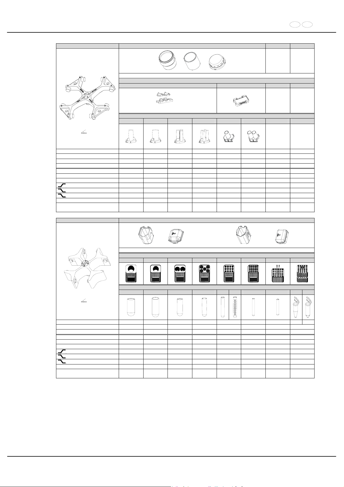
DE EN
83/104
5624 5620 + 4844 + 5280
+ +
Spannplatte / slide carrier
1670 1470
6)
2 x in 5280
Zyto-Kammer / cyto chamber
1665 1666 1667 1668 1471 1475
Ausschwingrotor 4-fach /
Swing out rotor 4-times
90°
Kapazität / capacity ml 4 8 3 x 2 4 x 1 1 x 8 2 x 8
Maße / dimensions / A
mm² 12,4 x 120 17,5 x 240 8,7 / 60 6,2 / 30 17,5 / 240 17,5 / 240
Anzahl p. Rotor / number p. rotor 16 16 16 16 8 8
Filterkarten / filter cards 1692 1691 1694 1693 --- ---
Drehzahl / speed RPM 4600 4600 4600 4600 4600 4600
RZB / RCF 3265/4589 3265/4589 3265/4589 3265/4589 3146/4471 3146/4471
Radius / radius mm 138 / 194 138 / 194 138 / 194 138 / 194 133 / 189 133 / 189
9 (97%)
sec 90 90 90 90 90 90
9
sec 95 95 95 95 95 95
0
sec 960 960 960 960 960 960
Temperatur / temperature °C 1) 4 4 4 4 4 4
Probenerwärmung/Sample
temp. rise
K
2)
18 18 18 18 18 18
5694 5091 + 5095 oder / or 5051 + 5053
14)
Gestell / frame
5262 5249 5243 5242 5248 5247 5227 5257
Röhrchen / tube
0526 0523 0521 0519
0507 0518
0578 0501
2078 0536
Ausschwingrotor 4-fach /
Swing out rotor 4-times
90°
Kapazität / capacity ml 100 100 50 25 15 7 6 1,5 2,0
Maße / dimensions x L
mm 44 x 100 40 x 115 34 x 100 24 x 100 17 x 100 12 x 100 12 x 82 11 x38
Anzahl p. Rotor / number p. rotor 4 4 8 20 48 80 80 160
Drehzahl / speed RPM 4000 4000 4000 4000 4000 4000 4000 4000
RZB / RCF 2755 2755 2755 2755 2755 2755 2773
1950/2826
Radius / radius mm 154 154 154 154 154 154 155 109/160
9 (97%)
sec 42 42 42 42 42 42 42 42
9
sec 51 51 51 51 51 51 51 51
0
sec 265 265 265 265 265 265 265 265
Temperatur / temperature °C 1) - 3 - 3 - 3 - 3 - 3 - 3 - 3 - 3
Probenerwärmung/Sample
temp. rise
K2) 14 14 14 14 14 14 14 14
1) Niedrigste Probentemperatur bei Vorkühlung und maximaler
Drehzahl (nur bei Kühlzentrifuge)
1) Lowest sample temperature with pre-cooling and maximum speed
(only with cooling centrifuges)
2) Probenerwärmung bei maximaler Drehzahl und
1 Stunde Laufzeit (nur bei Zentrifuge ohne Kühlung)
2) Sample temp. rise during maximum speed and 1 hour
running time (only with centrifuges without cooling)
6) Objektträger nur belastbar bis RZB 1100 6) Object slide will not stand RCF values exceeding 1100
14) Kunststoff-Nutgehänge dürfen nur bei Temperaturen bis maximal
40°C / 104°F verwendet werden.
14) Plastic suspension can only be used in temperatures up to a
maximum of 40°C / 104°F.
Page 84
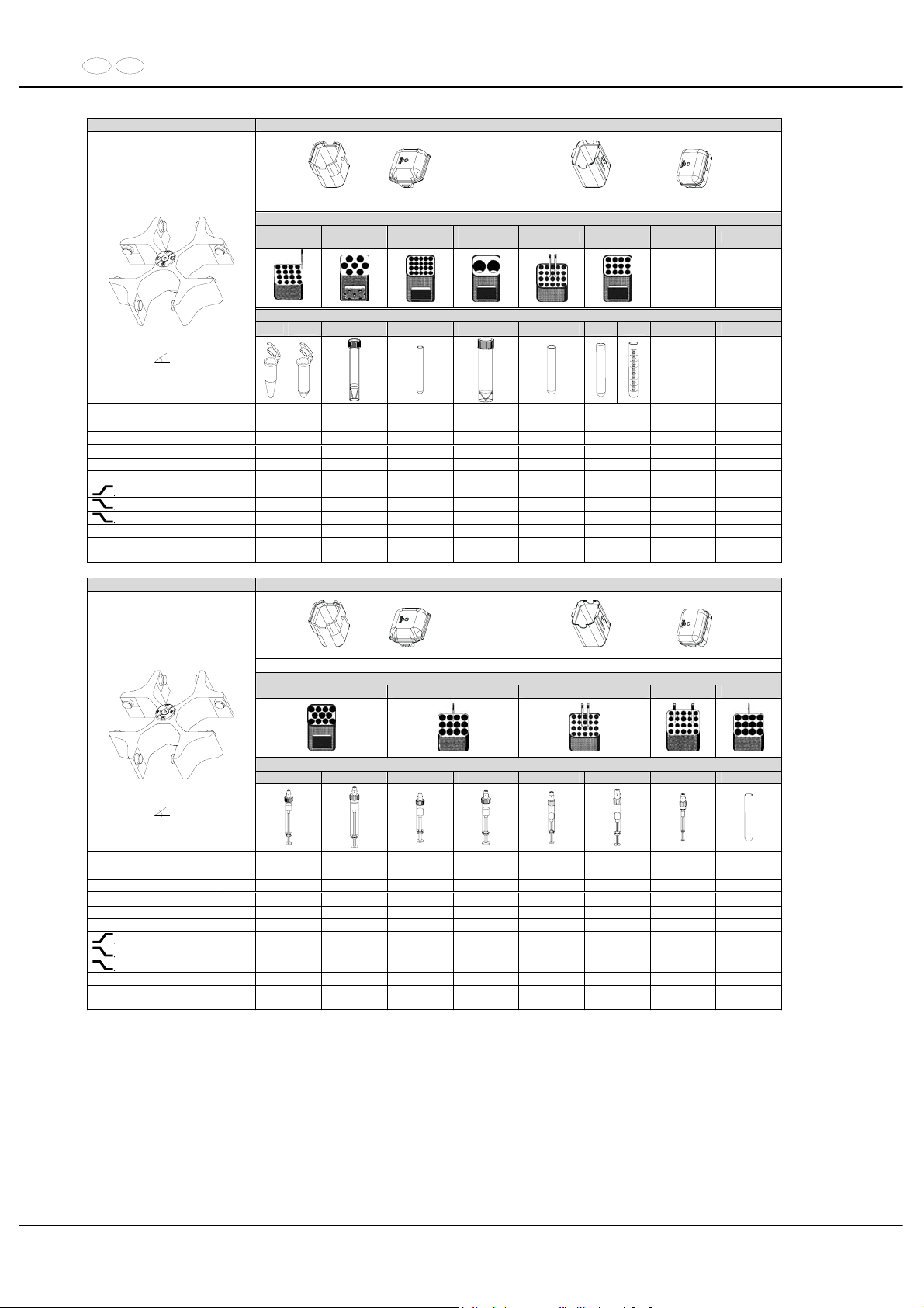
DE EN
84/104
5694 5091 + 5095 oder / or 5051 + 5053
14)
Gestell / frame
5281 6306
5247-91
9)
5243
4)
5227
5248-91
9)
Röhrchen / tube
2078 0536
----
0578 ---- 0553
0507 0518
Ausschwingrotor 4-fach /
Swing out rotor 4-times
90°
Kapazität / capacity ml 1,5 2,0 12 7 50 5 15
Maße / dimensions x L
mm 11 x 38 17 x 100 12 x 100 29 x 115 12 x 75 17 x 100
Anzahl p. Rotor / number p. rotor 64 28 80 8 80 48
Drehzahl / speed RPM 4000 4000 4000 4000 4000 4000
RZB / RCF 2826 2898 2755 2755 2773 2755
Radius / radius mm 158 162 154 154 155 154
9 (97%)
sec 42 42 42 42 42 42
9
sec 51 51 51 51 51 51
0
sec 265 265 265 265 265 265
Temperatur / temperature °C 1) - 3 - 3 - 3 - 3 - 3 - 3
Probenerwärmung/Sample
temp. rise
K2) 14 14 14 14 14 14
5694 5091 + 5095 oder / or 5051 + 5053
14)
Gestell / frame
5258 5264 5227 5267 5264
---- ---- ---- ---- ---- ---- ---- 0500
Ausschwingrotor 4-fach /
Swing out rotor 4-times
90°
Kapazität / capacity
1,5
9 - 10 10 4 - 5,5 7,5 -8,2 2,7 - 3 4,5 - 5 1,1; 1,2; 1,4 9
Maße / dimensions x L
mm 16 x 92 15 x 102 15 x 75 15 x 92 11 x 66 11 x 92 8 x 66 14 x 100
Anzahl p. Rotor / number p. rotor 44 44 48 48 80 80 80 48
Drehzahl / speed RPM 4000 4000 4000 4000 4000 4000 4000 4000
RZB / RCF 2755 2755 2773 2773 2773 2773 2737 2773
Radius / radius mm 154 154 155 155 155 155 153 155
9 (97%)
sec 42 42 42 42 42 42 42 42
9
sec 51 51 51 51 51 51 51 51
0
sec 265 265 265 265 265 265 265 265
Temperatur / temperature °C 1) - 3 - 3 - 3 - 3 - 3 - 3 - 3 - 3
Probenerwärmung/Sample
temp. rise
K2) 14 14 14 14 14 14 14 14
1) Niedrigste Probentemperatur bei Vorkühlung und maximaler
Drehzahl (nur bei Kühlzentrifuge)
1) Lowest sample temperature with pre-cooling and maximum speed (only
with cooling centrifuges)
2) Probenerwärmung bei maximaler Drehzahl und 1 Stunde
Laufzeit (nur bei Zentrifuge ohne Kühlung)
2) Sample temp. rise during maximum speed and 1 hour running time (only
with centrifuges without cooling)
3) Zentrifugiergefäße aus Glas nur belastbar bis RZB 4000 3) Centrifuge containers of glass will not stand RCF values exceeding 4000
4) nicht mit Deckel 5095 verschließbar 4) not closeable with lid 5095
9) mit Dekantierhilfe 9) with decanting aid
14) Kunststoff-Nutgehänge dürfen nur bei Temperaturen bis maximal
40°C / 104°F verwendet werden.
14) Plastic suspension can only be used in temperatures up to a maximum
of 40°C / 104°F.
Page 85
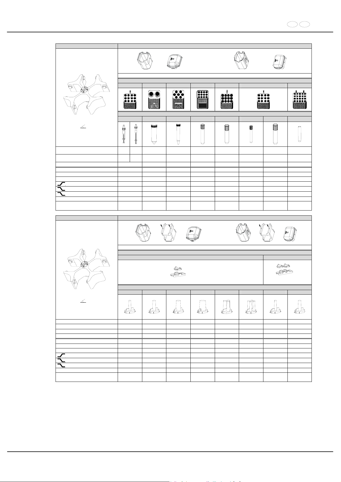
DE EN
85/104
5694 5091 + 5095 oder / or 5051 + 5053
14)
Gestell / frame
5268 5259 4) 6306 4) 5248 5264 5268 5267
Röhrchen / tube
---- 0513 0509 ---- ----
---
----
----
Ausschwingrotor 4-fach /
Swing out rotor 4-times
90°
Kapazität / capacity ml
2,6 ;
2,9
4,9
50 15 8,5 - 10 4 - 7 1,6 - 5 4 - 7 3
Maße / dimensions x L
mm
13 x 6513 x
90
29 x 115 17 x 120 16 x 100 16 x 75 13 x 75 13 x 100 10 x 60
Anzahl p. Rotor / number p. rotor 48 8 28 48 48 48 48 80
Drehzahl / speed RPM 4000 4000 4000 4000 4000 4000 4000 4000
RZB / RCF 2808 2844 2898 2755 2773 2808 2808 2737
Radius / radius mm 157 159 162 154 155 157 157 153
9 (97%)
sec 42 42 42 42 42 42 42 42
9
sec 51 51 51 51 51 51 51 51
0
sec 265 265 265 265 265 265 265 265
Temperatur / temperature °C 1) - 3 - 3 - 3 - 3 - 3 - 3 - 3 - 3
Probenerwärmung/Sample
temp. rise
K
2)
14 14 14 14 14 14 14 14
5694 5091 + 5280 + 5095 oder / or 5051 + 5280 5053
14)
Spannplatte / slide carrier
1662 1670
2 x in 5280
6)
2 x in 5280
Zyto-Kammer / cyto chamber
1663 1664 1665 1666 1667 1668 1663 1664
Ausschwingrotor4-fach /
Swing out rotor 4-times
90°
Kapazität / capacity ml 1 2 4 8 3 x 2 4 x 1 1 2
Maße / dimensions / A
mm² 6,2 / 30 8,7 / 60 12,4 / 120 17,5 / 240 8,7 / 60 6,2 / 30 6,2 / 30 8,7 x 60
Anzahl p. Rotor / number p. rotor 8 8 8 8 8 8 16 16
Filterkarten / filter cards 1675 1675 1675 1676 1677 1678 1692 1692
Drehzahl / speed RPM 4000 4000 4000 4000 4000 4000 4000 4000
RZB / RCF 1735/2737 1735/2737 1735/2737 1735/2737 1735/2737 1735/2737 1735/2737 1735/2737
Radius / radius mm 97 / 153 97 / 153 97 / 153 97 / 153 97 / 153 97 / 153 97 / 153 97 / 153
9 (97%)
sec 42 42 42 42 42 42 42 42
9
sec 51 51 51 51 51 51 51 51
0
sec 256 256 256 256 256 256 256 256
Temperatur / temperature °C 1) - 3 - 3 - 3 - 3 - 3 - 3 - 3 - 3
Probenerwärmung/Sample
temp. rise
K
2)
14 14 14 14 14 14 14 14
1) Niedrigste Probentemperatur bei Vorkühlung und maximaler
Drehzahl (nur bei Kühlzentrifuge)
1) Lowest sample temperature with pre-cooling and maximum speed (only
with cooling centrifuges)
2) Probenerwärmung bei maximaler Drehzahl und 1 Stunde
Laufzeit (nur bei Zentrifuge ohne Kühlung)
2) Sample temp. rise during maximum speed and 1 hour running time (only
with centrifuges without cooling)
4) nicht mit Deckel 5095 verschließbar 4) not closeable with lid 5095
6) Objektträger nur belastbar bis RZB 1100 6) Object slide will not stand RCF values exceeding 1100
14) Kunststoff-Nutgehänge dürfen nur bei Temperaturen bis maximal
40°C / 104°F verwendet werden.
14) Plastic suspension can only be used in temperatures up to a maximum
of 40°C / 104°F.
Page 86
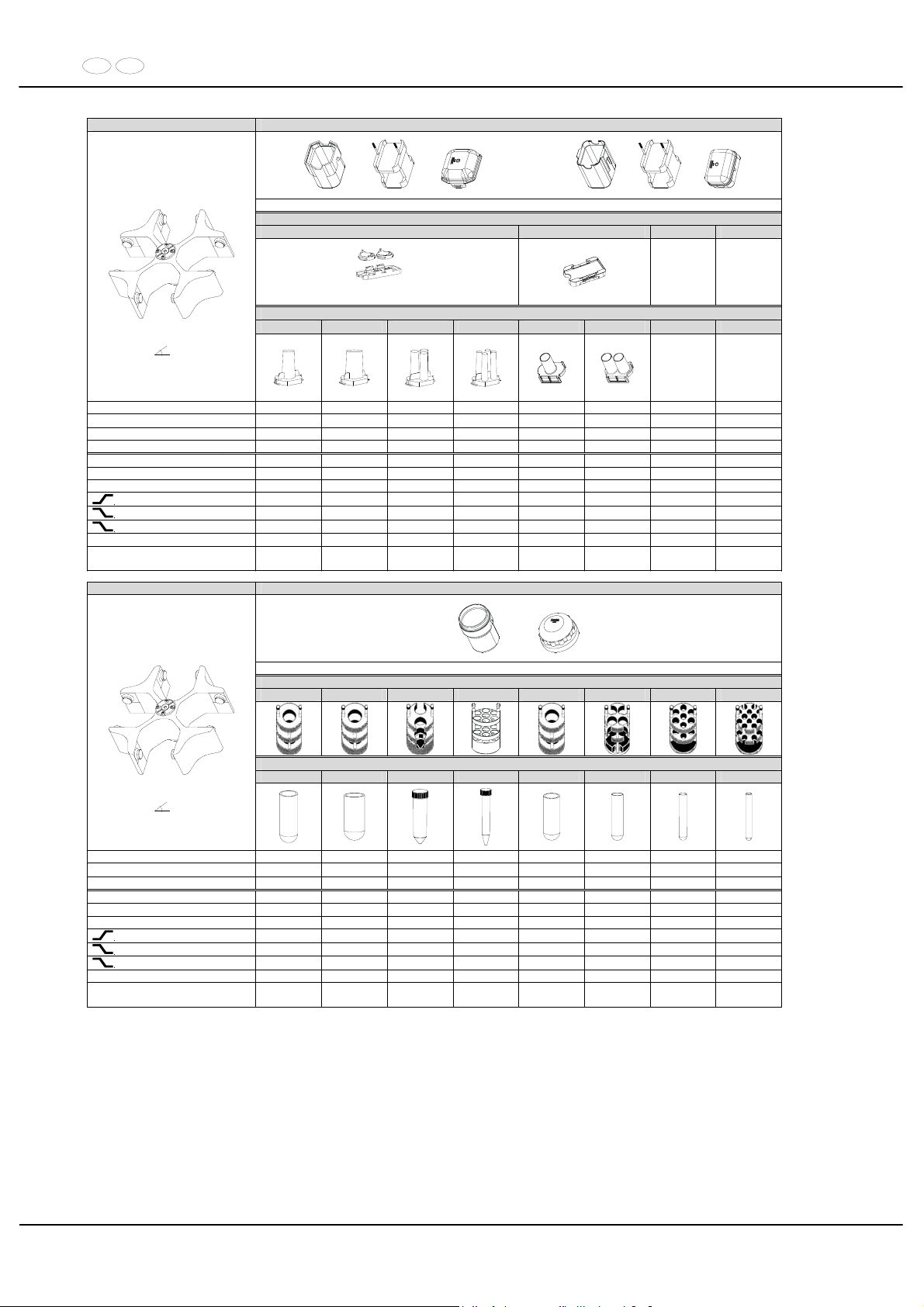
DE EN
86/104
5694 5091 + 5280 + 5095 oder / or 5051 + 5280 5053
14)
Spannplatte / slide carrier
1670 1470
6)
2 x in 5280
Zyto-Kammer / cyto chamber
1665 1666 1667 1668 1471 1475
Ausschwingrotor 4-fach /
Swing out rotor 4-times
90°
Kapazität / capacity ml 4 8 3 x 2 4 x 1 1 x 8 2 x 8
Maße / dimensions / A
mm² 12,4 x 120 17,5 x 240 8,7 / 60 6,2 / 30 17,5 / 240 17,5 / 240
Anzahl p. Rotor / number p. rotor 16 16 16 16 8 8
Filterkarten / filter cards 1692 1691 1694 1693 --- ---
Drehzahl / speed RPM 4000 4000 4000 4000 4000 4000
RZB / RCF 1735/2737 1735/2737 1735/2737 1735/2737 1664/2665 1664/2665
Radius / radius mm 97 / 153 97 / 153 97 / 153 97 / 153 93 / 149 93 / 149
9 (97%)
sec 42 42 42 42 42 42
9
sec 51 51 51 51 51 51
0
sec 256 256 256 256 256 256
Temperatur / temperature °C 1) - 3 - 3 - 3 - 3 - 3 - 3
Probenerwärmung/Sample
temp. rise
K2) 14 14 14 14 14 14
5694 5092 + 5093
mit Bioabdichtung / with bio-containment 12)
Reduzierung / adapter
5126 5125 5123 5129 11) 5124 5122 5121 5120
Röhrchen / tube
0523 0526 0513 0509 0521 0519 0507 0578
Ausschwingrotor 4-fach /
Swing out rotor 4-times
90°
Kapazität / capacity ml 100 100 50 15 50 25 15 7
Maße / dimensions x L
mm 40 x 115 44 x 100 29 x 115 17 x 120 34 x 100 24 x 100 17 x 100 12 x 100
Anzahl p. Rotor / number p. rotor 4 4 8 28 4 16 28 48
Drehzahl / speed RPM 4000 4000 4000 4000 4000 4000 4000 4000
RZB / RCF 2952 2952 3095 3095 2952 2898 3005 3005
Radius / radius mm 165 165 173 173 165 162 168 168
9 (97%)
sec 42 42 42 42 42 42 42 42
9
sec 51 51 51 51 51 51 51 51
0
sec 265 265 265 265 265 265 265 265
Temperatur / temperature °C 1) - 3 - 3 - 3 - 3 - 3 - 3 - 3 - 3
Probenerwärmung/Sample
temp. rise
K2) 14 14 14 14 14 14 14 14
1) Niedrigste Probentemperatur bei Vorkühlung und maximaler
Drehzahl (nur bei Kühlzentrifuge)
1) Lowest sample temperature with pre-cooling and maximum speed
(only with cooling centrifuges)
2) Probenerwärmung bei maximaler Drehzahl und
1 Stunde Laufzeit (nur bei Zentrifuge ohne Kühlung)
2) Sample temp. rise during maximum speed and 1 hour
running time (only with centrifuges without cooling)
6) Objektträger nur belastbar bis RZB 1100 6) Object slide will not stand RCF values exceeding 1100
11) Die Einlage aus den Gestellen entfernen 11) Take the inserts out of the frame / adapter
12) Nach DIN EN 61010, Teil 2 – 020. Die Hinweise für Bio-Sicher-
heitssysteme in den Kapiteln "Sicherheitshinweise" und "Pflege und
Wartung" beachten.
12) In conformity with DIN EN 61010, part 2 – 020. Observe the notes for
bio safety systems in chapters "Notes on safety" and "Maintenance
and servicing".
14) Kunststoff-Nutgehänge dürfen nur bei Temperaturen bis maximal
40°C / 104°F verwendet werden.
14) Plastic suspension can only be used in temperatures up to a
maximum of 40°C / 104°F.
Page 87
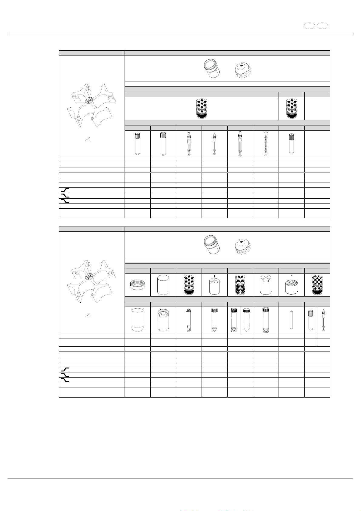
DE EN
87/104
5694 5092 + 5093
mit Bioabdichtung / with bio-containment 12)
Reduzierung / adapter
5121 5121-93
Röhrchen / tube
----
11)
---- ---- --- 0518 ----
Ausschwingrotor 4-fach /
Swing out rotor 4-times
90°
Kapazität / capacity ml 8,5 - 10 8 9 - 10 2,6 - 2,9 10 15 4 - 7
Maße / dimensions x L
mm 16 x 100 16 x 125 16 x 92 13 x 65 15 x 102 17 x 100 16 x 75
Anzahl p. Rotor / number p. rotor 28 28 28 28 28 28 28
Drehzahl / speed RPM 4000 4000 4000 4000 4000 4000 4000
RZB / RCF 3005 3059 3005 3005 3005 3005 3005
Radius / radius mm 168 171 168 168 168 168 168
9 (97%)
sec 42 42 42 42 42 42 42
9
sec 51 51 51 51 51 51 51
0
sec 265 265 265 265 265 265 265
Temperatur / temperature °C 1) - 3 - 3 - 3 - 3 - 3 - 3 - 3
Probenerwärmung/Sample
temp. rise
K2) 14 14 14 14 14 14 14
5694 5092 + 5093
mit Bioabdichtung / with bio-containment 12)
Reduzierung / adapter
1791 6319 5121 5134 5122 5135 5128 5120
Röhrchen / tubes
0530 5127 ---- ---- ---- ---- ---- ----
Ausschwingrotor 4-fach /
Swing out rotor 4-times
90°
Kapazität / capacity ml 250 250 12 25 30 50 5
4-7 4,5-5
Maße / dimensions x L
mm 65 x 115 62 x 122 17 x 100 25 x 90 25 x 110 29 x 115 13 x 75
13 x
100
11 x
92
Anzahl p. Rotor / number p. rotor 8 4 28 12 16 8 48 48
Drehzahl / speed RPM 4000 4000 4000 4000 4000 4000 4000 4000
RZB / RCF 3095 3095 3005 2826 2898 3023 3005 3005
Radius / radius mm 173 173 168 158 162 169 168 168
9 (97%)
sec 42 42 42 42 42 42 42 42
9
sec 51 51 51 51 51 51 51 51
0
sec 265 265 265 265 265 265 265 265
Temperatur / temperature °C 1) - 3 - 3 - 3 - 3 - 3 - 3 - 3 - 3
Probenerwärmung/Sample
temp. rise
K2) 14 14 14 14 14 14 14 14
1) Niedrigste Probentemperatur bei Vorkühlung und maximaler
Drehzahl (nur bei Kühlzentrifuge)
1) Lowest sample temperature with pre-cooling and maximum speed
(only with cooling centrifuges)
2) Probenerwärmung bei maximaler Drehzahl und
1 Stunde Laufzeit (nur bei Zentrifuge ohne Kühlung)
2) Sample temp. rise during maximum speed and 1 hour
running time (only with centrifuges without cooling)
11) Die Einlage aus den Gestellen entfernen 11) Take the inserts out of the frame / adapter
12) Nach DIN EN 61010, Teil 2 – 020. Die Hinweise für Bio-Sicher-
heitssysteme in den Kapiteln "Sicherheitshinweise" und "Pflege und
Wartung" beachten.
12) In conformity with DIN EN 61010, part 2 – 020. Observe the notes for
bio safety systems in chapters "Notes on safety" and "Maintenance
and servicing".
Page 88
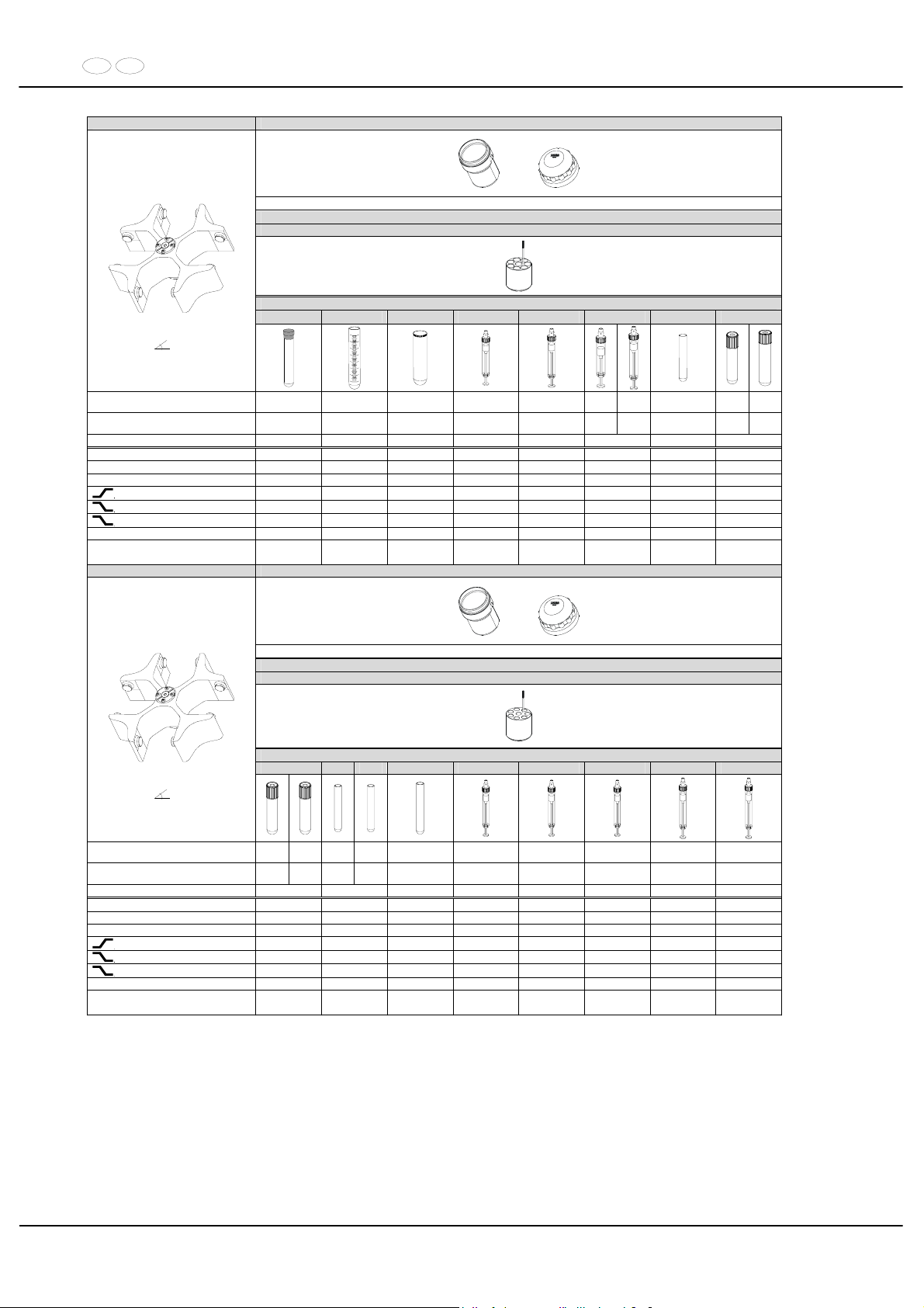
DE EN
88/104
5694 5092 + 5093
mit Bioabdichtung / with bio-containment 12)
Reduzierung / adapter
5136
Röhrchen / tubes
---- 0518 2079
---- ----
---- 0507
----
Ausschwingrotor 4-fach /
Swing out rotor 4-times
90°
Kapazität / capacity ml 10 15 10 4 – 4,5 7,5 - 8,2
9 10
10
15
4 - 7
8,5 -
10
Maße / dimensions x L
mm 16 x 80 17 x 100 17 x 70 15 x 75 15 x 92
16 x 9215 x
102
17 x 100
16 x 7516 x
100
Anzahl p. Rotor / number p. rotor 32 32 32 32 32 32 32 32
Drehzahl / speed RPM 4000 4000 4000 4000 4000 4000 4000 4000
RZB / RCF 2952 2952 2952 2952 2952 2952 2952 2952
Radius / radius mm 165 165 165 165 165 165 165 165
9 (97%)
sec 42 42 42 42 42 42 42 42
9
sec 51 51 51 51 51 51 51 51
0
sec 265 265 265 265 265 265 265 265
Temperatur / temperature °C 1) - 3 - 3 - 3 - 3 - 3 - 3 - 3 - 3
Probenerwärmung/Sample
temp. rise
K2) 14 14 14 14 14 14 14 14
5694 5092 + 5093
mit Bioabdichtung / with bio-containment 12)
Reduzierung / adapter
5137
Röhrchen / tubes
----
0553
---- 0501 ---- ---- ---- ---- ----
Ausschwingrotor 4-fach /
Swing out rotor 4-times
90°
Kapazität / capacity ml
1,6 -
5
4 - 7
5 5 6 1,1 - 1,4 2,6 -2,9 2,7 - 3 4,5 - 5 4,9
Maße / dimensions x L
mm
13 x 7513 x
100
12 x 7513 x
75
12 x 82 8 x 66 13 x 65 11 x 66 11 x 92 13 x 90
Anzahl p. Rotor / number p. rotor 32 32 32 32 32 32 32 32
Drehzahl / speed RPM 4000 4000 4000 4000 4000 4000 4000 4000
RZB / RCF 2952 2952 2952 2952 2952 2952 2952 2952
Radius / radius mm 165 165 165 165 165 165 165 165
9 (97%)
sec 42 42 42 42 42 42 42 42
9
sec 51 51 51 51 51 51 51 51
0
sec 265 265 265 265 265 265 265 265
Temperatur / temperature °C 1) - 3 - 3 - 3 - 3 - 3 - 3 - 3 - 3
Probenerwärmung/Sample
temp. rise
K
2)
14 14 14 14 14 14 14 14
1) Niedrigste Probentemperatur bei Vorkühlung und maximaler
Drehzahl (nur bei Kühlzentrifuge)
1) Lowest sample temperature with pre-cooling and maximum speed
(only with cooling centrifuges)
2) Probenerwärmung bei maximaler Drehzahl und
1 Stunde Laufzeit (nur bei Zentrifuge ohne Kühlung)
2) Sample temp. rise during maximum speed and 1 hour
running time (only with centrifuges without cooling)
12) Nach DIN EN 61010, Teil 2 – 020. Die Hinweise für Bio-Sicher-
heitssysteme in den Kapiteln "Sicherheitshinweise" und "Pflege und
Wartung" beachten.
12) In conformity with DIN EN 61010, part 2 – 020. Observe the notes
for bio safety systems in chapters "Notes on safety" and
"Maintenance and servicing".
Page 89
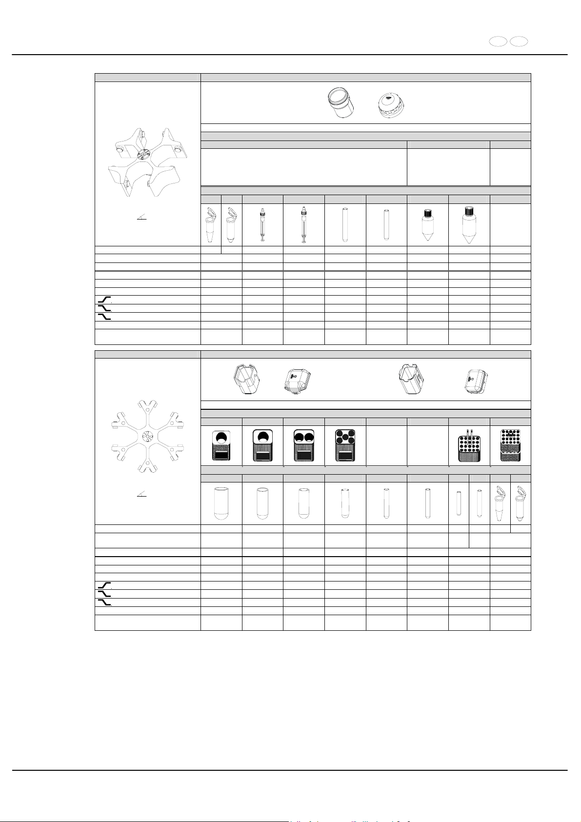
DE EN
89/104
5694 5092 + 5093
mit Bioabdichtung / with bio-containment 12)
Reduzierung / adapter
SK 21.00 SK. 94.89
Röhrchen / tubes
2078 0536
---- ----
---- ----
Falcon
®
Falcon
®
Ausschwingrotor 4-fach /
Swing out rotor 4-times
90°
Kapazität / capacity ml 1,5 2,0 1,1 - 1,4 2,7 - 3 4 3 175 225
Maße / dimensions x L
mm 11 x38 8 x 66 11 x 66 10 x 88 10 x 60 61 x 118 61 x 137
Anzahl p. Rotor / number p. rotor 40 40 40 40 40 4 4
Drehzahl / speed RPM 4000 4000 4000 4000 4000 4000
RZB / RCF 2916 2916 2916 2916 2916 3095 3095
Radius / radius mm 163 163 163 163 163 173 173
9 (97%)
sec 42 42 42 42 42 42 42
9
sec 51 51 51 51 51 51 51
0
sec 265 265 265 265 265 265 265
Temperatur / temperature °C 1) - 3 - 3 - 3 - 3 - 3 - 3 - 3
Probenerwärmung/Sample
temp. rise
K
2)
14 14 14 14 14 14 14
4446 5091 + 5095 oder / or 5051 + 5053
14)
Gestell / frame
5262 5249 5243 5242 5248 5247 5227 5257
5248-91
9)
5247-91
9)
Röhrchen / tube
0526 0523 0521 0519 0507 0578
0553 0501 2078 0536
Ausschwingrotor 6-fach /
Swing out rotor 6-times
90°
Kapazität / capacity ml 100 100 50 25 15 7 5 6 1,5 2,0
Maße / dimensions x L
mm 44 x 100 40 x 115 34 x 100 24 x 100 17 x 100 12 x 100
12 x 7512 x
82
11 x38
Anzahl p. Rotor / number p. rotor 6 6 12 30 72 120 120 240
Drehzahl / speed RPM 4000 4000 4000 4000 4000 4000 4000 4000
RZB / RCF 3291 3291 3291 3291 3291 3291 3309 2486/3363
Radius / radius mm 184 184 184 184 184 184 185 139/188
9 (97%)
sec 45 45 45 45 45 45 45 45
9
sec 55 55 55 55 55 55 55 55
0
sec 551 551 551 551 551 551 551 551
Temperatur / temperature °C 1) 0 0 0 0 0 0 0 0
Probenerwärmung/Sample
temp. rise
K
2)
14 14 14 14 14 14 14 14
1) Niedrigste Probentemperatur bei Vorkühlung und maximaler
Drehzahl (nur bei Kühlzentrifuge)
1) Lowest sample temperature with pre-cooling and maximum speed
(only with cooling centrifuges)
2) Probenerwärmung bei maximaler Drehzahl und
1 Stunde Laufzeit (nur bei Zentrifuge ohne Kühlung)
2) Sample temp. rise during maximum speed and 1 hour
running time (only with centrifuges without cooling)
9) mit Dekantierhilfe 9) with decanting aid
12) Nach DIN EN 61010, Teil 2 – 020. Die Hinweise für Bio-Sicher-
heitssysteme in den Kapiteln "Sicherheitshinweise" und "Pflege und
Wartung" beachten.
12) In conformity with DIN EN 61010, part 2 – 020. Observe the notes for
bio safety systems in chapters "Notes on safety" and "Maintenance
and servicing".
14) Kunststoff-Nutgehänge dürfen nur bei Temperaturen bis maximal
40°C / 104°F verwendet werden.
14) Plastic suspension can only be used in temperatures up to a
maximum of 40°C / 104°F.
Page 90
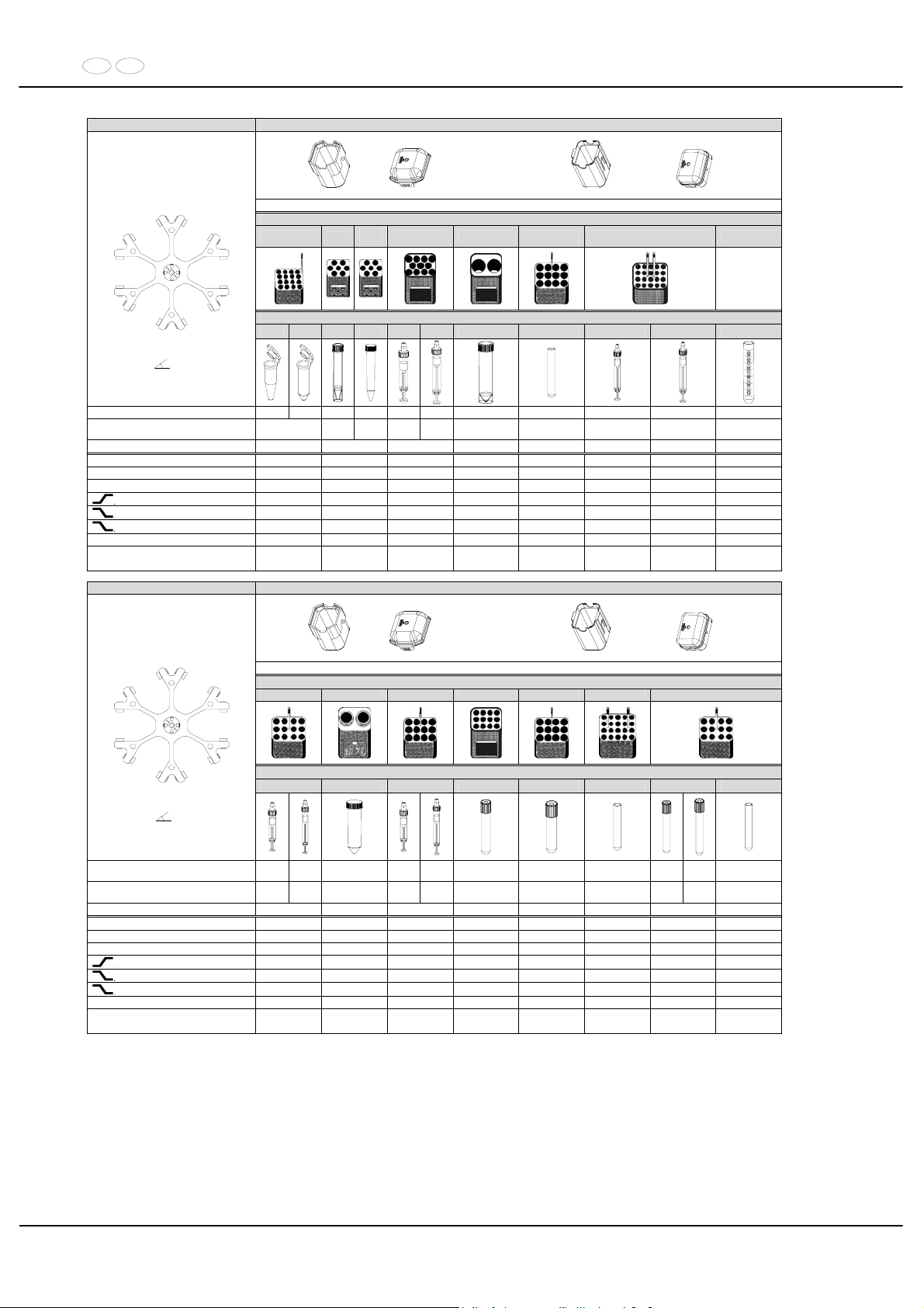
DE EN
90/104
4446 5091 + 5095 oder / or 5051 + 5053
14)
Gestell / frame
5281
6306
6306
4)
5258 4) 5243 4) 5264 5227 5248
5248-91
9)
Röhrchen / tube
2078 0536
---
0509
--- 0500 ---- ---- 0518
Ausschwingrotor 6-fach /
Swing out rotor 6-times
90°
Kapazität / capacity ml 1,5 2,0
12 15 9-10
10 50 9 2,7 - 3 4,5 - 5 15
Maße / dimensions x L
mm 11 x 38
17 x
100
17 x
120
16x 9215x
102
29 x 115 14 x 100 11 x66 11 x 92 17 x 100
Anzahl p. Rotor / number p. rotor 96 42 66 12 72 120 120 72
Drehzahl / speed RPM 4000 4000 4000 4000 4000 4000 4000 4000
RZB / RCF 3363 3434 3291 3291 3309 3309 3309 3291
Radius / radius mm 188 192 184 184 185 185 185 184
9 (97%)
sec 45 45 45 45 45 45 45 45
9
sec 55 55 55 55 55 55 55 55
0
sec 551 551 551 551 551 551 551 551
Temperatur / temperature °C 1) 0 0 0 0 0 0 0 0
Probenerwärmung/Sample
temp. rise
K
2)
14 14 14 14 14 14 14 14
4446 5091 + 5095 oder / or 5051 + 5053
14)
Gestell / frame
5268 5259 4) 5264 5248 5264 5267 5268
Röhrchen / tube
---- 0513 ---- ---- ----
----
----
----
Ausschwingrotor 6-fach /
Swing out rotor 6-times
90°
Kapazität / capacity ml
2,6 ;
2,9
4,9
50
4 - 5, 57,5 x
8,2
8,5 - 10 4 - 7 3
1,6 –
5
4-7
5
Maße / dimensions x L
mm
13 x 6513 x
90
30 x 115
15 x 7515 x
92
16 x 100 16 x 75 10 x 60
13 x 7513 x
100
13 x 75
Anzahl p. Rotor / number p. rotor 72 12 72 72 72 120 72 72
Drehzahl / speed RPM 4000 4000 4000 4000 4000 4000 4000 4000
RZB / RCF 3345 3363 3309 3291 3309 3274 3345 3345
Radius / radius mm 187 188 185 184 185 183 187 187
9 (97%)
sec 45 45 45 45 45 45 45 45
9
sec 55 55 55 55 55 55 55 55
0
sec 551 551 551 551 551 551 551 551
Temperatur / temperature °C 1) 0 0 0 0 0 0 0 0
Probenerwärmung/Sample
temp. rise
K2) 14 14 14 14 14 14 14 14
1) Niedrigste Probentemperatur bei Vorkühlung und maximaler
Drehzahl (nur bei Kühlzentrifuge)
1) Lowest sample temperature with pre-cooling and maximum speed
(only with cooling centrifuges)
2) Probenerwärmung bei maximaler Drehzahl und
1 Stunde Laufzeit (nur bei Zentrifuge ohne Kühlung)
2) Sample temp. rise during maximum speed and 1 hour
running time (only with centrifuges without cooling)
4) nicht mit Deckel 5095 verschließbar 4) not closeable with lid 5095
9) mit Dekantierhilfe 9) with decanting aid
14) Kunststoff-Nutgehänge dürfen nur bei Temperaturen bis maximal
40°C / 104°F verwendet werden.
14) Plastic suspension can only be used in temperatures up to a
maximum of 40°C / 104°F.
Page 91
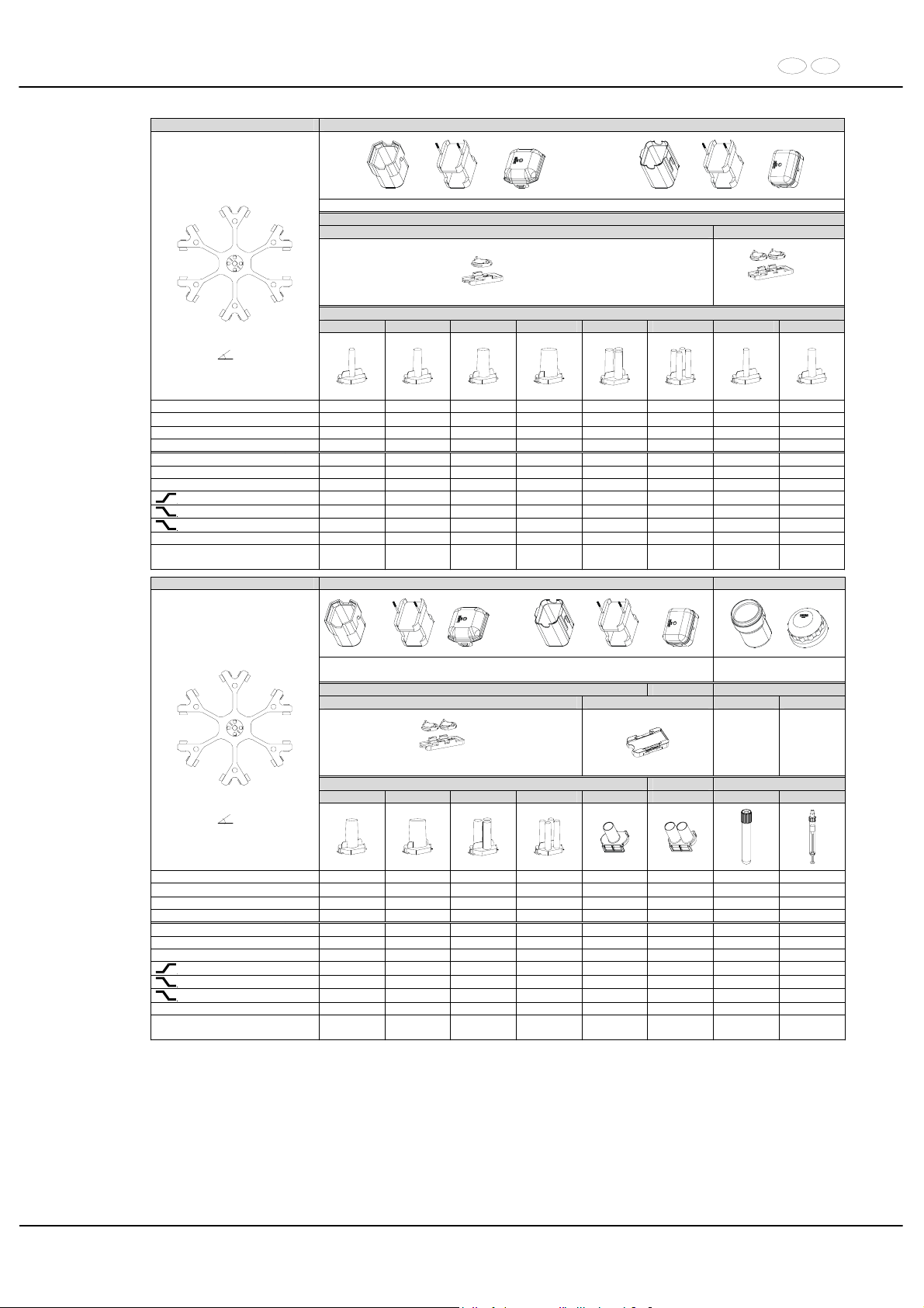
DE EN
91/104
4446 5091 + 5280 + 5095 oder / or 5051 + 5280 5053
14)
Spannplatte / slide carrier
1662 1670
2 x in 5280
6)
2 x in 5280
Zyto-Kammer / cyto chamber
1663 1664 1665 1666 1667 1668 1663 1664
Ausschwingrotor 6-fach /
Swing out rotor 6-times
90°
Kapazität / capacity ml 1 2 4 8 3 x 2 4 x 1 1 2
Maße / dimensions / A
mm² 6,2 / 30 8,7 / 60 12,4 / 120 17,5 / 240 8,7 / 60 6,2 / 30 6,2 / 30 8,7 / 60
Anzahl p. Rotor / number p. rotor 12 12 12 12 12 12 24 24
Filterkarten / filter cards 1675 1675 1675 1676 1677 1678 1692 1692
Drehzahl / speed RPM 4000 4000 4000 4000 4000 4000 4000 4000
RZB / RCF 2290/3291 2290/3291 2290/3291 2290/3291 2290/3291 2290/3291 2290/3291 2290/3291
Radius / radius mm 128 / 184 128 / 184 128 / 184 128 / 184 128 / 184 128 / 184 128 / 184 128 / 184
9 (97%)
sec 45 45 45 45 45 45 45 45
9
sec 55 55 55 55 55 55 55 55
0
sec 551 551 551 551 551 551 551 551
Temperatur / temperature °C 1) 0 0 0 0 0 0 0 0
Probenerwärmung/Sample
temp. rise
K
2)
14 14 14 14 14 14 14 14
4446 5091 + 5280 + 5095 oder / or 5051 + 5280 5053 5092 + 5093
14)
aerosoldicht / aerosol-
proof 12)
Spannplatte / slide carrier Reduzierung / adapter
1670 1470 5121 5120
6)
2 x in 5280
Zyto-Kammer / cyto chamber Röhrchen / tube
1665 1666 1667 1668 1471 1475 ---- -----
Ausschwingrotor 6-fach /
Swing out rotor 6-times
90°
Kapazität / capacity ml 4 8 3 x 2 4 x 1 1 x 8 2 x 8 8 4,5 - 5
Maße / dimensions / A
mm² 12,4 / 120 17,5 / 240 8,7 / 60 6,2 / 30 17,5 / 240 17,5 / 240 16 x 125 11 x 92
Anzahl p. Rotor / number p. rotor 24 24 24 24 12 12 42 72
Filterkarten / filter cards 1692 1691 1694 1693 --- --- --- --Drehzahl / speed RPM 4000 4000 4000 4000 4000 4000 4000 4000
RZB / RCF 2290/3291 2290/3291 2290/3291 2290/3291 2200/3202 2200/3202 3542 3542
Radius / radius mm 128 / 184 128 / 184 128 / 184 128 / 184 123/179 123/179 198 198
9 (97%)
sec 45 45 45 45 45 45 45 45
9
sec 55 55 55 55 55 55 55 55
0
sec 551 551 551 551 551 551 551 551
Temperatur / temperature °C 1) 0 0 0 0 0 0 0 0
Probenerwärmung/Sample
temp. rise
K2) 14 14 14 14 14 14 14 14
1) Niedrigste Probentemperatur bei Vorkühlung und maximaler
Drehzahl (nur bei Kühlzentrifuge)
1) Lowest sample temperature with pre-cooling and maximum speed
(only with cooling centrifuges)
2) Probenerwärmung bei maximaler Drehzahl und
1 Stunde Laufzeit (nur bei Zentrifuge ohne Kühlung)
2) Sample temp. rise during maximum speed and 1 hour
running time (only with centrifuges without cooling)
4) nicht mit Deckel 5095 verschließbar 4) not closeable with lid 5095
6) Objektträger nur belastbar bis RZB 1100 6) Object slide will not stand RCF values exceeding 1100
12) Nach DIN EN 61010, Teil 2 – 020. Die Hinweise für Bio-Sicher-
heitssysteme in den Kapiteln "Sicherheitshinweise" und "Pflege und
Wartung" beachten.
12) In conformity with DIN EN 61010, part 2 – 020. Observe the notes for
bio safety systems in chapters "Notes on safety" and "Maintenance
and servicing".
14) Kunststoff-Nutgehänge dürfen nur bei Temperaturen bis maximal
40°C / 104°F verwendet werden.
14) Plastic suspension can only be used in temperatures up to a
maximum of 40°C / 104°F.
Page 92
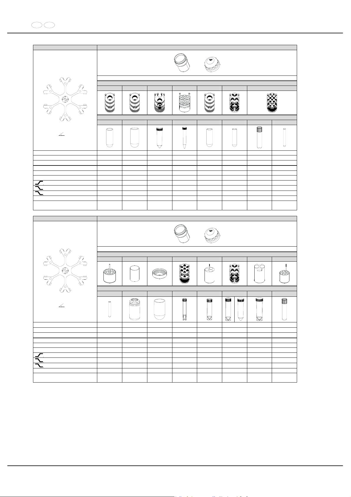
DE EN
92/104
4446 5092 + 5093
mit Bioabdichtung / with bio-containment 12)
Reduzierung / adapter
5126 5125 5123 5129 11) 5124 5122 5120
Röhrchen / tube
0523 0526 0513 0509 0521 0519 0578
Ausschwingrotor 6-fach /
Swing out rotor 6-times
90°
Kapazität / capacity ml 100 100 50 15 50 25 4 - 7 7
Maße / dimensions x L
mm 40 x 115 44 x 100 30 x 115 17 x 120 34 x 100 24 x 100 13 x 100 12 x 100
Anzahl p. Rotor / number p. rotor 6 6 12 42 6 24 72 72
Drehzahl / speed RPM 4000 4000 4000 4000 4000 4000 4000 4000
RZB / RCF 3488 3488 3631 3631 3631 3434 3542 3542
Radius / radius mm 195 195 203 203 195 192 198 198
9 (97%)
sec 45 45 45 45 45 45 45 45
9
sec 55 55 55 55 55 55 55 55
0
sec 551 551 551 551 551 551 551 551
Temperatur / temperature °C 1) 0 0 0 0 0 0 0 0
Probenerwärmung/Sample
temp. rise
K
2)
14 14 14 14 14 14 14 14
4446 5092 + 5093
mit Bioabdichtung / with bio-containment 12)
Reduzierung / adapter
5128 6319 4) 1791 5121 5134 5122 5135 5136
Röhrchen / tubes
0501 5127 0530
---- ---- ---- ----
----
Ausschwingrotor 6-fach /
Swing out rotor 6-times
90°
Kapazität / capacity ml 5 250 250
12
25 30 50 8,5 - 10
Maße / dimensions x L
mm 13 x 75 62 x 122 65 x 115 17 x 100 25 x 90 25 x 110 29 x 115 16 x 100
Anzahl p. Rotor / number p. rotor 72 6 6 42 18 24 12 48
Drehzahl / speed RPM 4000 4000 4000 4000 4000 4000 4000 4000
RZB / RCF 3542 3631 3631 3542 3363 3327 3560 3488
Radius / radius mm 198 203 203 198 188 186 199 195
9 (97%)
sec 45 45 45 45 45 45 45 45
9
sec 55 55 55 55 55 55 55 55
0
sec 551 551 551 551 551 551 551 551
Temperatur / temperature °C 1) 0 0 0 0 0 0 0 0
Probenerwärmung/Sample
temp. rise
K2) 14 14 14 14 14 14 14 14
1) Niedrigste Probentemperatur bei Vorkühlung und maximaler
Drehzahl (nur bei Kühlzentrifuge)
1) Lowest sample temperature with pre-cooling and maximum speed
(only with cooling centrifuges)
2) Probenerwärmung bei maximaler Drehzahl und
1 Stunde Laufzeit (nur bei Zentrifuge ohne Kühlung)
2) Sample temp. rise during maximum speed and 1 hour
running time (only with centrifuges without cooling)
4) nicht mit Deckel 5093 verschließbar 4) not closeable with lid 5093
11) Die Einlage aus den Gestellen entfernen 11) Take the inserts out of the frame / adapter
12) Nach DIN EN 61010, Teil 2 – 020. Die Hinweise für Bio-Sicher-
heitssysteme in den Kapiteln "Sicherheitshinweise" und "Pflege und
Wartung" beachten.
12) In conformity with DIN EN 61010, part 2 – 020. Observe the notes
for bio safety systems in chapters "Notes on safety" and
"Maintenance and servicing".
Page 93
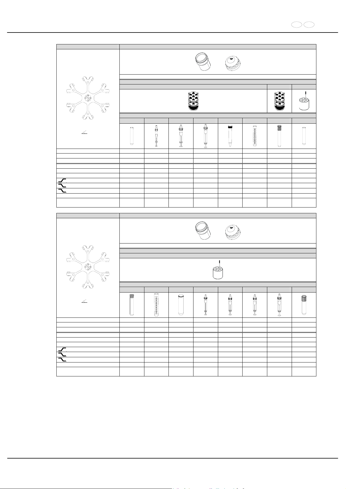
DE EN
93/104
4446 5092 + 5093
mit Bioabdichtung / with bio-containment 12)
Reduzierung / adapter
5121 5121-93 5136
Röhrchen / tubes
0507
---- ---- ----
0509 4) 0518
----
0507
Ausschwingrotor 6-fach /
Swing out rotor 6-times
90°
Kapazität / capacity ml 15 2,6 – 2,9 9 - 10 10 15 15 4 - 7 15
Maße / dimensions x L
mm 17 x 100 13 x 65 16 x 92 15 x 102 17 x 120 17 x 100 16 x 75 17 x 100
Anzahl p. Rotor / number p. rotor 42 42 42 42 42 42 42 48
Drehzahl / speed RPM 4000 4000 4000 4000 4000 4000 4000 4000
RZB / RCF 3542 3542 3542 3542 3542 3542 3542 3488
Radius / radius mm 198 198 198 198 198 198 198 195
9 (97%)
sec 45 45 45 45 45 45 45 45
9
sec 55 55 55 55 55 55 55 55
0
sec 551 551 551 551 551 551 551 551
Temperatur / temperature °C 1) 0 0 0 0 0 0 0 0
Probenerwärmung/Sample
temp. rise
K2) 14 14 14 14 14 14 14 14
4446 5092 + 5093
mit Bioabdichtung / with bio-containment 12)
Reduzierung / adapter
5136
Röhrchen / tubes
---- 0518 2079
---- ----
----
---- ----
Ausschwingrotor 6-fach /
Swing out rotor 6-times
90°
Kapazität / capacity ml 10 15 10 4 – 4,5 7,5 - 8,2 9 - 10 10 4 - 7
Maße / dimensions x L
mm 16 x 80 17 x 100 17 x 70 15 x 75 15 x 92 16 x 92 15 x 102 16 x 75
Anzahl p. Rotor / number p. rotor 48 48 48 48 48 48 48 48
Drehzahl / speed RPM 4000 4000 4000 4000 4000 4000 4000 4000
RZB / RCF 3488 3488 3488 3488 3488 3488 3488 3488
Radius / radius mm 195 195 195 195 195 195 195 195
9 (97%)
sec 45 45 45 45 45 45 45 45
9
sec 55 55 55 55 55 55 55 55
0
sec 551 551 551 551 551 551 551 551
Temperatur / temperature °C 1) 0 0 0 0 0 0 0 0
Probenerwärmung/Sample
temp. rise
K2) 14 14 14 14 14 14 14 14
1) Niedrigste Probentemperatur bei Vorkühlung und maximaler
Drehzahl (nur bei Kühlzentrifuge)
1) Lowest sample temperature with pre-cooling and maximum speed
(only with cooling centrifuges)
2) Probenerwärmung bei maximaler Drehzahl und
1 Stunde Laufzeit (nur bei Zentrifuge ohne Kühlung)
2) Sample temp. rise during maximum speed and 1 hour
running time (only with centrifuges without cooling)
4) nicht mit Deckel 5093 verschließbar 4) not closeable with lid 5093
12) Nach DIN EN 61010, Teil 2 – 020. Die Hinweise für Bio-Sicher-
heitssysteme in den Kapiteln "Sicherheitshinweise" und "Pflege und
Wartung" beachten.
12) In conformity with DIN EN 61010, part 2 – 020. Observe the notes for
bio safety systems in chapters "Notes on safety" and "Maintenance
and servicing".
Page 94
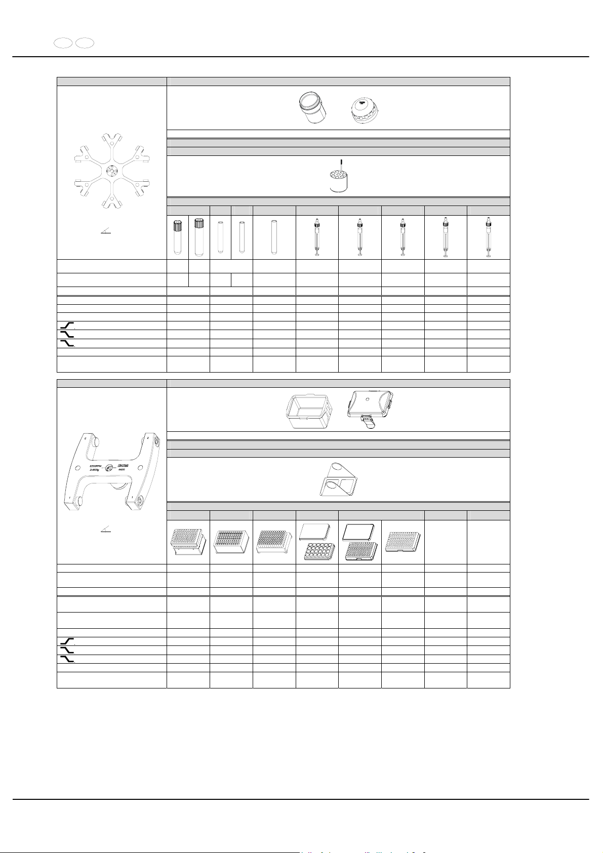
DE EN
94/104
4446 5092 + 5093
mit Bioabdichtung / with bio-containment 12)
Reduzierung / adapter
5137
Röhrchen / tubes
----
0553
---
0501 ---- ---- ---- ---- ----
Ausschwingrotor 6-fach /
Swing out rotor 6-times
90°
Kapazität / capacity ml
1,6 -
5
4 – 7
5 6 1,1 - 1,4 2,6 -2,9 2,7 - 3 4,5 - 5 4,9
Maße / dimensions x L
mm
13 x 7513 x
100
12 x 7513 x
75
12 x 82 8 x 66 13 x 65 11 x 66 11 x 92 13 x 90
Anzahl p. Rotor / number p. rotor 48 48 48 48 48 48 48 48
Drehzahl / speed RPM 4000 4000 4000 4000 4000 4000 4000 4000
RZB / RCF 3488 3488 3488 3488 3488 3488 3488 3488
Radius / radius mm 195 195 195 195 195 195 195 195
9 (97%)
sec 45 45 45 45 45 45 45 45
9
sec 55 55 55 55 55 55 55 55
0
sec 551 551 551 551 551 551 551 551
Temperatur / temperature °C 1) 0 0 0 0 0 0 0 0
Probenerwärmung/Sample
temp. rise
K
2)
14 14 14 14 14 14 14 14
4620 4623 + 4627
mit Bioabdichtung / with bio-containment 12)
4626
Platten / plates
QP DWP MS CP MTP
Ausschwingrotor 2-fach /
Swing out rotor 2-times
90°
Kapazität / capacity ml --- --- --- --- --- ---
Maße / dimensions
TxBxH / DxWxH
mm
86x128x83 86x128x44,5 86x128x46 86x128x22 86x128x17,5 86x128x15
Anzahl p. Rotor / number p. rotor 2 2 2 8 10 12
Drehzahl / speed RPM
5900 /
(6200) *
5900 /
(6200) *
5900 /
(6200) *
5900 /
(6200) *
5900 /
(6200) *
5900 /
(6200) *
RZB / RCF
5215/
(5759) *
5215/
(5759) *
5215/
(5759) *
5215/
(5759) *
5215/
(5759) *
5215/
(5759) *
Radius / radius mm 134 134 134 134 134 134
9 (97%)
sec 50 / (55) * 50 / (55) * 50 / (55) * 50 / (55) * 50 / (55) * 50 / (55) *
9
sec 48 / (53) * 48 / (53) * 48 / (53) * 48 / (53) * 48 / (53) * 48 / (53) *
0
sec 600 600 600 600 600 600
Temperatur / temperature °C 1) 12 12 12 12 12 12
Probenerwärmung/Sample
temp. rise
K
2)
10 10 10 10 10 10
1) Niedrigste Probentemperatur bei Vorkühlung und maximaler
Drehzahl (nur bei Kühlzentrifuge)
1) Lowest sample temperature with pre-cooling and maximum speed
(only with cooling centrifuges)
2) Probenerwärmung bei maximaler Drehzahl und
1 Stunde Laufzeit (nur bei Zentrifuge ohne Kühlung)
2) Sample temp. rise during maximum speed and 1 hour running
time (only with centrifuges without cooling)
* (nur bei Kühlzentrifuge) * (only with cooling centrifuges)
12) Nach DIN EN 61010, Teil 2 – 020. Die Hinweise für Bio-Sicherheitssysteme
in den Kapiteln "Sicherheitshinweise" und "Pflege und Wartung" beachten.
12) In conformity with DIN EN 61010, part 2 – 020. Observe the notes for bio safety
systems in chapters "Notes on safety" and "Maintenance and servicing".
MTP Mikrotiterplatte /
Microtitre plate
CP Kulturplatte /
Culture plate
DWP Deep Well Platte /
Deep well plate
MS Micronic System /
Micronic system
QP Filterplatte /
Filter plate
Page 95
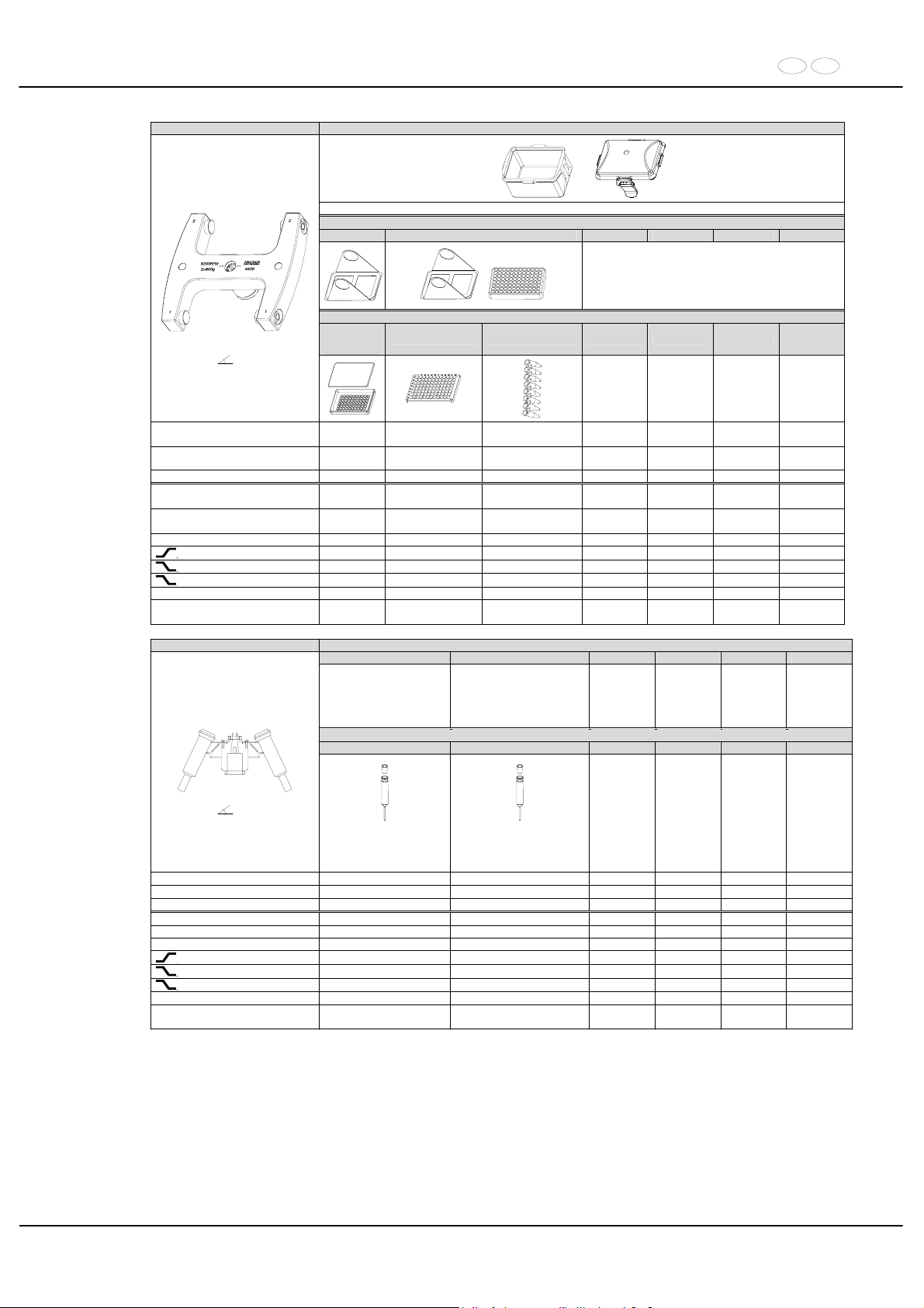
DE EN
95/104
4620 4623 + 4627
mit Bioabdichtung / with bio-containment 12)
4626 4626 + 1469
+
Platten / plates
Microtest-
platten / plate
Terasaki
96-PCR-Platte / plate
PCR-Strips
Ausschwingrotor 2-fach /
Swing out rotor 2-times
90°
Kapazität / capacity ml --- ---
0,2
---
Maße / dimensions
TxBxH / DxWxH
mm 59x84x11 82x124x20
---
Anzahl p. Rotor / number p. rotor 4 2 24
Drehzahl / speed RPM
5900 /
(6200) *
5900 /
(6200) *
5900 /
(6200) *
RZB / RCF
5215 /
(5759) *
5215 /
(5759) *
5215 /
(5759) *
Radius / radius mm 134 134 134
9 (97%)
sec 50 / (55) * 50 / (55) * 50 / (55) *
9
sec 48 / (53) * 48 / (53) * 48 / (53) *
0
sec 600 600 600
Temperatur / temperature °C 1) 12 12 12
Probenerwärmung/Sample
temp. rise
K2) 10 10 10
4619 Reduzierung / adapter
---
Röhrchen / tube
0508 7) 0529 7)
Ausschwingrotor 6-fach /
Swing out rotor 6-times
90°
Chrombad-Röhrchen /
Chromium bath tube
Scale 1 µl – 35 µl, 5 ml, 30 ml
Kapillare / capillary 1,1 mm
Chrombad-Röhrchen /
Chromium bath tube
Scale 10 µl – 350 µl, 5 ml, 30 ml
Kapillare / capillary 3,5 mm
Kapazität / capacity ml 30 30
Maße / dimensions x L
mm 24 x 151 24 x 151
Anzahl p. Rotor / number p. rotor 6 6
Drehzahl / speed RPM 2000 2000
RZB / RCF 917 917
Radius / radius mm 205 205
9 (97%)
sec 17 17
9
sec 21 21
0
sec 286 286
Temperatur / temperature °C 1) - 11 - 11
Probenerwärmung/Sample
temp. rise
K2) 2 2
1) Niedrigste Probentemperatur bei Vorkühlung und maximaler
Drehzahl (nur bei Kühlzentrifuge)
1) Lowest sample temperature with pre-cooling and maximum speed
(only with cooling centrifuges)
2) Probenerwärmung bei maximaler Drehzahl und
1 Stunde Laufzeit (nur bei Zentrifuge ohne Kühlung)
2) Sample temp. rise during maximum speed and 1 hour running
time (only with centrifuges without cooling)
* (nur bei Kühlzentrifuge) * (only with cooling centrifuges)
7) nicht mit Stopfen zentrifugierbar 7) can not be centrifugated when plug is attached
12) Nach DIN EN 61010, Teil 2 – 020. Die Hinweise für Bio-Sicher-
heitssysteme in den Kapiteln "Sicherheitshinweise" und "Pflege
und Wartung" beachten.
12) In conformity with DIN EN 61010, part 2 – 020. Observe the notes for bio
safety systems in chapters "Notes on safety" and "Maintenance and
servicing".
Page 96
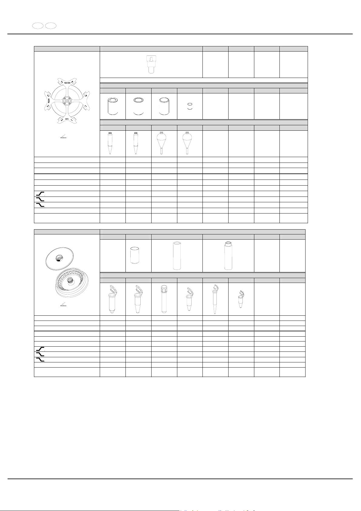
DE EN
96/104
4474 4275
Reduzierung / Reduction
4276 4277 4278 0771
Röhrchen / tube
0531 --- --- 0528
Ausschwingrotor 4-fach /
Swing out rotor 4-times
90°
8) 8)
8) 8)
Kapazität / capacity ml 100 100 50 100
Maße / dimensions x L
mm 37 x 200 44 x 168 45 x 130 58 x 161
Anzahl p. Rotor / number p. rotor 4 4 4 4
Drehzahl / speed RPM 2000 2000 2000 2000
RZB / RCF 966 966 984 984
Radius / radius mm 216 216 220 220
9 (97%)
sec 17 17 17 17
9
sec 20 20 20 20
0
sec 195 195 195 195
Temperatur / temperature °C 1) - 8 - 8 - 8 - 8
Probenerwärmung/Sample
temp. rise
K2) 8 8 8 8
4489 Reduzierung / adapter
--- 2031 2023 2024
13)
Röhrchen / tube
0536 2078 --- --- --- ---
Winkelrotor 30-fach /
Angle rotor 30-times
45°
mit Bioabdichtung /
with bio-containment
12)
Kapazität / capacity ml 2,0 1,5 0,8 0,5 0,4 0,2
Maße / dimensions x L
mm 11 x 38 11 x 38 8 x 45 8 x 30 6 x 45 6 x 18
Anzahl p. Rotor / number p. rotor 30 30 30 30 30 30
Drehzahl / speed RPM 15000 15000 15000 15000 15000 15000
RZB / RCF
3)
max. 24400 max. 24400 max. 24400 max. 24400 max. 24400 max. 24400
Radius / radius mm max. 97 max. 97 max. 97 max. 97 max. 97 max. 97
9 (97%)
sec 73 73 73 73 73 73
9
sec 77 77 77 77 77 77
0
sec 240 240 240 240 240 240
Temperatur / temperature °C 1) 7 7 7 7 7 7
Probenerwärmung/Sample
temp. rise
K
2)
18 18 18 18 18 18
1) Niedrigste Probentemperatur bei Vorkühlung und maximaler
Drehzahl (nur bei Kühlzentrifuge)
1) Lowest sample temperature with pre-cooling and maximum speed
(only with cooling centrifuges)
2) Probenerwärmung bei maximaler Drehzahl und
1 Stunde Laufzeit (nur bei Zentrifuge ohne Kühlung)
2) Sample temp. rise during maximum speed and 1 hour running
time (only with centrifuges without cooling)
3) Zentrifugiergefäße aus Glas nur belastbar bis RZB 4000 3) Centrifuge containers of glass will not stand RCF values exceeding 4000
8) Gefäß nur belastbar bis RZB 700 8) tube will not stand RCF values exceeding 700
12) Nach DIN EN 61010, Teil 2 – 020. Die Hinweise für Bio-Sicher-
heitssysteme in den Kapiteln "Sicherheitshinweise" und "Pflege
und Wartung" beachten.
12) In conformity with DIN EN 61010, part 2 – 020. Observe the notes for bio
safety systems in chapters "Notes on safety" and "Maintenance and
servicing".
13) bei hochtouriger Zentrifugation empfohlen 13) recommended for high-speed centrifugation
Page 97
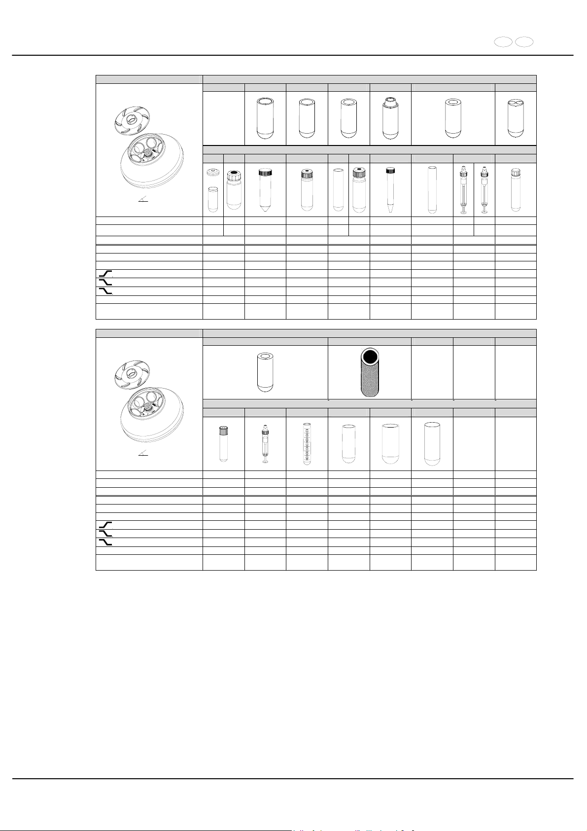
DE EN
97/104
5615 Reduzierung / adapter
--- 1454 1446 1447 1466 1451 1448
Röhrchen / tube
0547
0513 0546 0519 0545 0509 0507
----
----
Winkelrotor 6-fach /
Angle rotor 6-times
45°
mit Bioabdichtung /
with bio-containment
12)
0539
+
0538
Kapazität / capacity ml 94 85 50 50 25 30 15 15
7,5 - 8,2
9 - 10
10
Maße / dimensions x L
mm
38 x
110,5
38 x
106
29 x 115 29 x 107
24 x
100
26 x
95
17 x 120 17x100
15 x 9216 x
92
16 x 80
Anzahl p. Rotor / number p. rotor 6 6 6 6 6 6 6 12
Drehzahl / speed RPM 11500 11500 11500 11500 11500 11500 11500 11500
RZB / RCF
3)
18038 17595 17299 16560 17299 17003 17003 17003
Radius / radius mm 122 119 117 112 117 115 115 115
9 (97%)
sec 66 66 66 66 66 66 66 66
9
sec 68 68 68 68 68 68 68 68
0
sec 641 641 641 641 641 641 641 641
Temperatur / temperature °C 1) 4 4 4 4 4 4 4 4
Probenerwärmung/Sample
temp. rise
K2) 19 19 19 19 19 19 19 19
5615 Reduzierung / adapter
1451 1463 ---
Röhrchen / tube
----
----
0518 0521 0548 0549
----
Winkelrotor 6-fach /
Angle rotor 6-times
45°
mit Bioabdichtung /
with bio-containment
12)
Kapazität / capacity ml 8,5 - 10 10 15 50 75 85
Maße / dimensions x L
mm 16 x 100 15 x 102 17 x 100 34 x 100 35 x 105 38 x 106
Anzahl p. Rotor / number p. rotor 6 6 6 6 6 6
Drehzahl / speed RPM 11500 11500 11500 11500 11500 11500
RZB / RCF
3)
17003 17003 17003 17743 17743 18038
Radius / radius mm 115 115 115 120 120 122
9 (97%)
sec 66 66 66 66 66 66
9
sec 68 68 68 68 68 68
0
sec 641 641 641 641 641 641
Temperatur / temperature °C 1) 4 4 4 4 4 4
Probenerwärmung/Sample
temp. rise
K2) 19 19 19 19 19 19
1) Niedrigste Probentemperatur bei Vorkühlung und maximaler
Drehzahl (nur bei Kühlzentrifuge)
1) Lowest sample temperature with pre-cooling and maximum speed (only
with cooling centrifuges)
2) Probenerwärmung bei maximaler Drehzahl und 1 Stunde
Laufzeit (nur bei Zentrifuge ohne Kühlung)
2) Sample temp. rise during maximum speed and 1 hour running time (only
with centrifuges without cooling)
3) Zentrifugiergefäße aus Glas nur belastbar bis RZB 4000 3) Centrifuge containers of glass will not stand RCF values exceeding 4000
12) Nach DIN EN 61010, Teil 2 – 020. Die Hinweise für Bio-Sicherheitssysteme in den Kapiteln "Sicherheitshinweise" und "Pflege
und Wartung" beachten.
12) In conformity with DIN EN 61010, part 2 – 020. Observe the notes for bio
safety systems in chapters "Notes on safety" and "Maintenance and
servicing".
Page 98
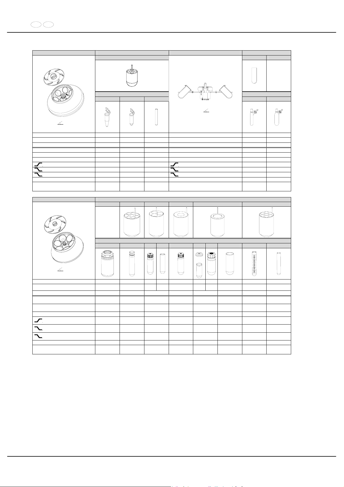
DE EN
98/104
5615 Reduzierung / adapter 5616 Reduzierung / adapter
1449 4317 ----
Röhrchen / tube Röhrchen / tube
2078 0536
---
0532 0533
Winkelrotor 6-fach /
Angle rotor 6-times
45°
mit Bioabdichtung /
-
12)
Winkelrotor 6-fach /
Angle rotor 6-times
45 °
Kapazität / capacity ml 1,5 2,0 3 Kapazität / capacity ml 25 50
Maße / dimensions x L
mm 11 x 38 11 x 38 10 x 60
Maße / dimensions x L
mm 24 x 146,5 38 x 148,5
Anzahl p. Rotor / number p. rotor
24 24 24
Anzahl p. Rotor / number p. rotor 6 6
Drehzahl / speed RPM 11500 11500 11500 Drehzahl / speed RPM 2000 2000
RZB / RCF
3)
17299 17299 17299 RZB / RCF 783 805
Radius / radius mm 117 117 117 Radius / radius mm 175 180
9 (97%)
sec 66 66 66
9 (97%)
sec 17 17
9
sec 68 68 68
9
sec 21 21
0
sec 641 641 641
0
sec 286 286
Temperatur / temperature °C 1) 4 4 4 Temperatur / temperature °C 1) - 14 - 14
Probenerwärmung/Sample
temp. rise
K
2)
19 19 19
Probenerwärmung/Sample
temp. rise
K2) 10 10
5645 Reduzierung / adapter
--- 5641 5642 5643 5644 5646
Röhrchen / tube
5127 ---
0545 0519
0546
0547
0549 0518 0507
Winkelrotor 6-fach /
Angle rotor 6-times
25°
mit Bioabdichtung /
wi
thbio-conta
inmen
t
12)
0539
+
0538
Kapazität / capacity ml 250 10 30 25 50 94 85 85 15 15
Maße / dimensions x L
mm 61,5 x 122 16 x 80
26 x 9524 x
100
29 x 107
38 x
106
38 x
106
38 x 106 17 x 100 17 x 100
Anzahl p. Rotor / number p. rotor 6 48 18 6 6 42 42 42
Drehzahl / speed RPM
8500
(9500)*
8500
(9500)*
8500
(9500)*
8500
(9500)*
8500
(9500)*
8500
(9500)*
8500
(9500)*
8500
(9500)*
RZB / RCF
3)
11228
(14025)*
10743
(13420)*
10339
(12915)*
9693
(12108)*
9855
(12310)*
9855
(12310)*
10662
(13319)*
10662
(13319)*
Radius / radius mm 139 133 128 120 122 122 132 132
9 (97%)
sec
98 /
(115)*
98 /
(115)*
98 /
(115)*
98 /
(115)*
98 /
(115)*
98 /
(115)*
98 /
(115)*
98 /
(115)*
9
sec
105
(120)*
105
(120)*
105
(120)*
105
(120)*
105
(120)*
105
(120)*
105
(120)*
105
(120)*
0
sec
1110
(1103)*
1110
(1103)*
1110
(1103)*
1110
(1103)*
1110
(1103)*
1110
(1103)*
1110
(1103)*
1110
(1103)*
Temperatur / temperature °C 1) 4 4 4 4 4 4 4 4
Probenerwärmung/Sample
temp. rise
K2) 18 18 18 18 18 18 18 18
1) Niedrigste Probentemperatur bei Vorkühlung und maximaler
Drehzahl (nur bei Kühlzentrifuge)
1) Lowest sample temperature with pre-cooling and maximum speed (only
with cooling centrifuges)
2) Probenerwärmung bei maximaler Drehzahl und 1 Stunde
Laufzeit (nur bei Zentrifuge ohne Kühlung)
2) Sample temp. rise during maximum speed and 1 hour running time (only
with centrifuges without cooling)
3) Zentrifugiergefäße aus Glas nur belastbar bis RZB 4000 3) Centrifuge containers of glass will not stand RCF values exceeding 4000
* (nur bei Kühlzentrifuge) * (only with cooling centrifuges)
12) Nach DIN EN 61010, Teil 2 – 020. Die Hinweise für Bio-Sicher-
heitssysteme in den Kapiteln "Sicherheitshinweise" und "Pflege
und Wartung" beachten.
12) In conformity with DIN EN 61010, part 2 – 020. Observe the notes for bio
safety systems in chapters "Notes on safety" and "Maintenance and
servicing".
Page 99
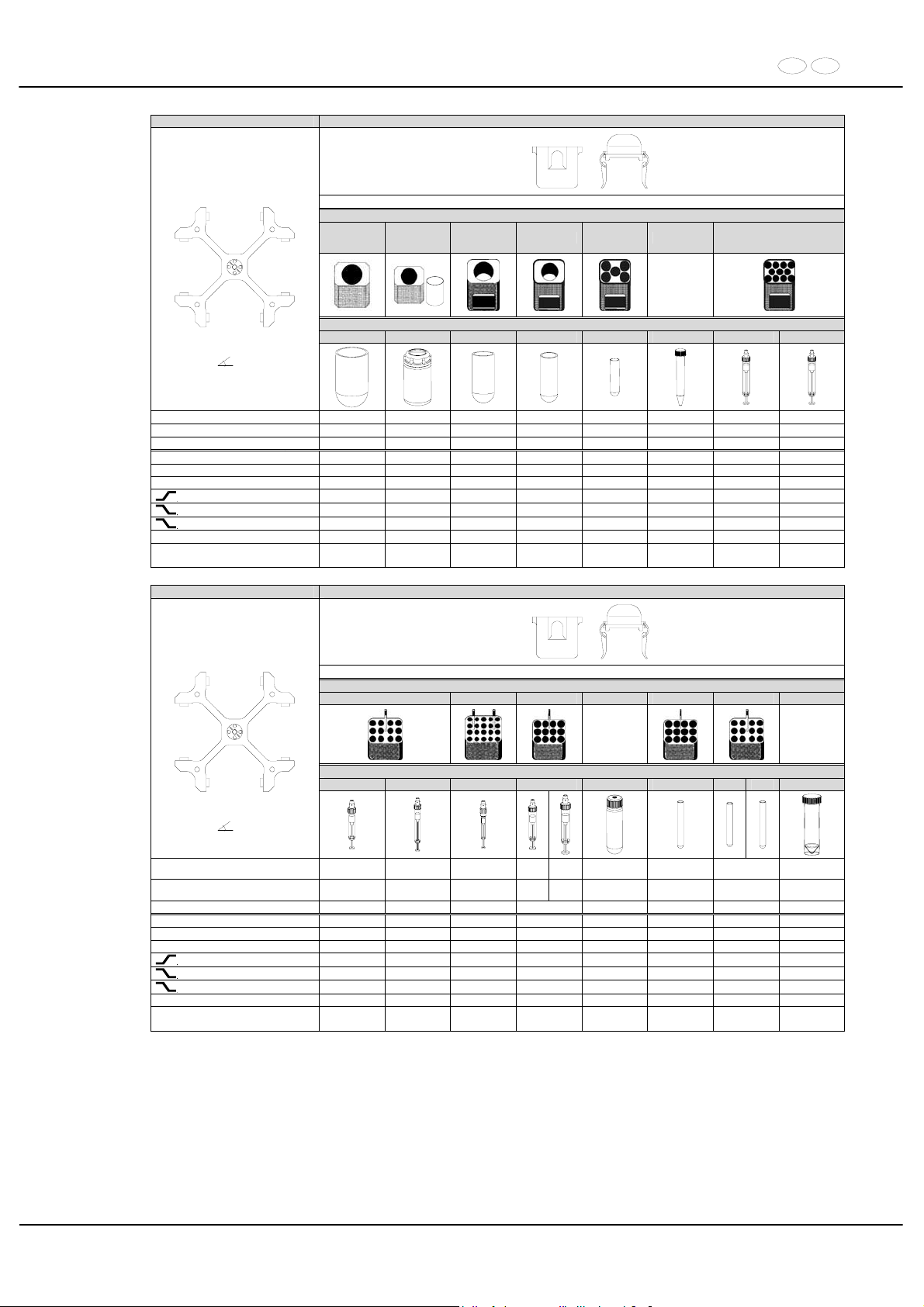
DE EN
99/104
4444 4412 + 4414
mit Bioabdichtung / with bio-containment 12)
Gestell / frame
5263-A
5263-A +
6319 11)
5262 5249 5242 5258
SK.110.97
Röhrchen / tube
0530 5127 0526 0523 0519 0509 ---- ----
Ausschwingrotor 4-fach /
Swing out rotor 4-times
90°
Kapazität / capacity ml 250 250 100 100 25 15 7,5 - 8,2 9 - 10
Maße / dimensions x L
mm 65 x 115 62 x 122 44 x 100 40 x 115 24 x 100 17 x 120 15 x 92 16 x 92
Anzahl p. Rotor / number p. rotor 4 4 8 8 40 44 88 88
Drehzahl / speed RPM 4500 4500 4500 4500 4500 4500 4500 4500
RZB / RCF
3)
4256 4392 4279 4279 4302 4460 4302 4302
Radius / radius mm 188 194 189 189 190 197 190 190
9 (97%)
sec 78 78 78 78 78 78 78 78
9
sec 75 75 75 75 75 75 75 75
0
sec 1080 1080 1080 1080 1080 1080 1080 1080
Temperatur / temperature °C 1) 6 6 6 6 6 6 6 6
Probenerwärmung/Sample
temp. rise
K
2)
19 19 19 19 19 19 19 19
4444 4412 + 4414
mit Bioabdichtung / with bio-containment 12)
Gestell / frame
5268 5267 5264 SK 34.90 5264 5268 5243+6316
4) 4)
Röhrchen / tube
---- ---- ---- ---- 0546 0500
0501 0578
---
Ausschwingrotor 4-fach /
Swing out rotor 4-times
90°
Kapazität / capacity ml 2,6 ; 2,9 4,9 1,1; 1,2; 1,4
4 -
5,5
7,5 –
8,2
50 9 1,6 - 7 50
Maße / dimensions x L
mm 13 x 65 13 x 90 8 x 66
15 x 7515 x
92
29 x 107 14 x 100 13 x 75/100 29 x 115
Anzahl p. Rotor / number p. rotor 96 96 160 96 24 96 96 16
Drehzahl / speed RPM 4500 4500 4500 4500 4500 4500 4500 4500
RZB / RCF
3)
4369 4369 4279 4324 4324 4369 4302
Radius / radius mm 193 193 189 191 191 193 190
9 (97%)
sec 78 78 78 78 78 78 78 78
9
sec 75 75 75 75 75 75 75 75
0
sec 1080 1080 1080 1080 1080 1080 1080 1080
Temperatur / temperature °C 1) 6 6 6 6 6 6 6 6
Probenerwärmung/Sample
temp. rise
K
2)
19 19 19 19 19 19 19 19
1) Niedrigste Probentemperatur bei Vorkühlung und maximaler
Drehzahl (nur bei Kühlzentrifuge)
1) Lowest sample temperature with pre-cooling and maximum speed (only
with cooling centrifuges)
2) Probenerwärmung bei maximaler Drehzahl und 1 Stunde
Laufzeit (nur bei Zentrifuge ohne Kühlung)
2) Sample temp. rise during maximum speed and 1 hour running time (only
with centrifuges without cooling)
3) Zentrifugiergefäße aus Glas nur belastbar bis RZB 4000 3) Centrifuge containers of glass will not stand RCF values exceeding 4000
4) nicht mit Deckel 4414 verschließbar 4) not closeable with lid 4414
11) Die Einlagen aus den Gestellen / Reduzierungen entfernen 11) Take the inserts out of the frames / adapters
12) Nach DIN EN 61010, Teil 2 – 020. Die Hinweise für Bio-Sicher-
heitssysteme in den Kapiteln "Sicherheitshinweise" und "Pflege
und Wartung" beachten.
12) In conformity with DIN EN 61010, part 2 – 020. Observe the notes for bio
safety systems in chapters "Notes on safety" and "Maintenance and
servicing".
Page 100
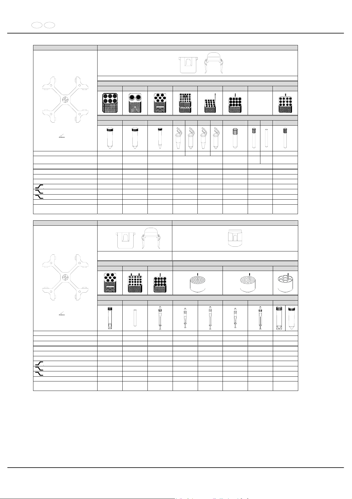
DE EN
100/104
4444 4412 + 4414
mit Bioabdichtung / with bio-containment 12)
Gestell / frame
5269 5259 6306 4) 5257 5281 5264 6301 5268
2 x in 4412
Röhrchen / tube
0513 0513 0509
2078 0536 2078 0536
---- ----
0578
----
Ausschwingrotor 4-fach /
Swing out rotor 4-times
90°
Kapazität / capacity ml 50 50 15 1,5 2,0 1,5 2,0 4 - 7
4 - 7
7 1,6 - 7
Maße / dimensions x L
mm 29 x 115 29 x 115 17 x 120 11 x 38 11 x 38 16 x 75
13 x
100
12 x
100
13 x 75/100
Anzahl p. Rotor / number p. rotor 24 16 56 320 128 96 96 96
Drehzahl / speed RPM 4500 4500 4500 4500 4500 4500 4500 4500
RZB / RCF
3)
4460 4392 4460 3260/4369 4369 4324 4302 4369
Radius / radius mm 197 194 197 144 / 193 193 191 190 193
9 (97%)
sec 78 78 78 78 78 78 78 78
9
sec 75 75 75 75 75 75 75 75
0
sec 1080 1080 1080 1080 1080 1080 1080 1080
Temperatur / temperature °C 1) 6 6 6 6 6 6 6 6
Probenerwärmung/Sample
temp. rise
K
2)
19 19 19 19 19 19 19 19
4444 4412 + 4414 4413
mit Bioabdichtung / with bio-
containment 12)
Gestell / frame Reduzierung / adapter
6306 5267 5264 4433 4435 4438
---- ---- ---- ---- ---- ---- ---- ----
Ausschwingrotor 4-fach /
Swing out rotor 4-times
90°
Kapazität / capacity ml 12 3 10 2,7 – 3 4,5 - 5 2,6 x 2,9 4,9 30
Maße / dimensions x L
mm
17 x 100/120
10 x 60 15 x 102 11 x 66 11 x 92 13 x 65 13 x 90 25 x 110
Anzahl p. Rotor / number p. rotor 56 160 96 120 120 84 84 28
Drehzahl / speed RPM 4500 4500 4500 4500 4500 4500 4500 4500
RZB / RCF
3)
4460 4279 4324 4211 4211 4211 4211 4279
Radius / radius mm 197 189 191 186 186 186 186 189
9 (97%)
sec 78 78 78 78 78 78 78 78
9
sec 75 75 75 75 75 75 75 75
0
sec 1080 1080 1080 1080 1080 1080 1080 1080
Temperatur / temperature °C 1) 6 6 6 3 3 3 3 3
Probenerwärmung/Sample
temp. rise
K2) 19 19 19 18 18 18 18 18
1) Tiefste erreichbare Temperatur bei maximaler Drehzahl, 1 h
Laufzeit und 20°C Raumtemperatur (nur bei Kühlzentrifuge)
1) Lowest possible temperature during maximum speed, 1 h running time
and 20°C ambient temperature (only with cooling centrifuges)
2) Probenerwärmung bei maximaler Drehzahl und 1 Stunde Laufzeit
(nur bei Zentrifuge ohne Kühlung)
2) Sample temp. rise during maximum speed and 1 hour running time (only
with centrifuges without cooling)
3) Zentrifugiergefäße aus Glas nur belastbar bis RZB 4000 3) Centrifuge containers of glass will not stand RCF values exceeding 4000
4) nicht mit Deckel 4414 verschließbar 4) not closeable with lid 4414
12) Nach DIN EN 61010, Teil 2 – 020. Die Hinweise für Bio-Sicher-
heitssysteme in den Kapiteln "Sicherheitshinweise" und "Pflege
und Wartung" beachten.
12) In conformity with DIN EN 61010, part 2 – 020. Observe the notes for bio
safety systems in chapters "Notes on safety" and "Maintenance and
servicing".
 Loading...