

Page 1
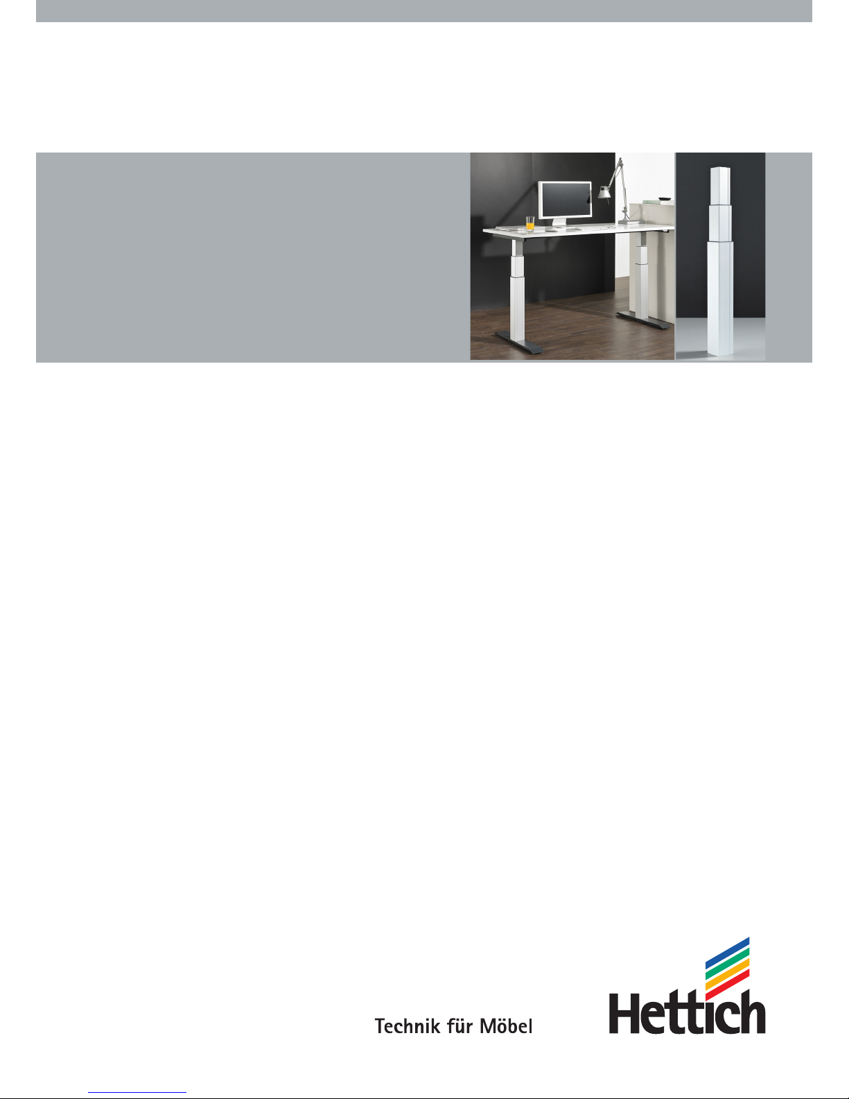
Operating and installation instructions
LegaDrive
Page 2
2
(Copy of the original)
Operating and installation instructions
under EC Machinery Directive 2006/42/EC,
Annex VI for partly completed machinery
Lifting column system for an electrically
height adjustable workstation
Type: LegaDrive
Manufacturer: Paul Hettich GmbH & Co. KG
Vahrenkampstr. 12-16
32278 Kirchlengern
Year built: 2014
Date / eective: 2018-05 / 03
Foreword
Customer Service
Hettich Marketing- und Vertriebs GmbH & Co. KG
Vahrenkampstr. 12-16
D-32278 Kirchlengern
Please contact the person responsible at the
Hettich Customer Service.
Copyright to these operating and installation instructions
© 2014 held by Paul Hettich GmbH & Co. KG
The copyright to these operating and installation instructions
remains with Paul Hettich GmbH & Co. KG.
These operating and installation instructions are intended for
personnel installing the LegaDrive. It contains regulations and
drawings of a technical nature that must not be duplicated
either in whole or in part, distributed, used without
permission for advertising purposes or communicated to
others.
Warning
Read these operating and installation instruc-
tions carefully in order to obtain a thorough
understanding of the lifting column and how to
install it. Install the lifting column as described
in these instructions so as to avoid injury and
damage to the lifting column. Do not install the
lifting column on the basis of suppositions. Keep
these operating and installation instructions to
hand and consult them if you are in any doubt as
to carrying out any particular procedure.
Before installing the lifting column, settle any
unanswered questions first by consulting Paul
Hettich GmbH & Co. KG.
These operating and installation instructions are
a separate part of the overall documentation. The
overall documentation must be made available
to installation, operating and servicing personnel.
Page 3

3
6.2.2.2 Replacing the battery 29
6.2.3 Connecting optional components 29
6.2.4 Plugging in power supply cable 30
6.3 Overall configuration (example) 30
7. Operation 31
7.1 Basic functions 31
7.1.1 Upward desk top movement 32
7.1.2 Downward desk top movement 32
7.2. Display functions 33
7.3. Display lock 33
7.4 Extended functions 34
7.4.1 Memorising a desk top position 34
7.4.2 Adjusting desk top to a memorised position 35
7.4.3 Changing desk top position height display 35
7.4.4 Manual reset 36
7.5 Software related functions 36
7.5.1 Low speed areas 36
7.5.2 ON time monitor 36
7.5.3 Safety zone 37
7.5.4 Pedestal stop and shelf stop positions 37
7.5.5 Plug detection 39
7.5.6 Auto detect number of drives 39
7.5.7 Collision detection (Drive back) 39
7.5.8 Changing desk height unit (cm or inch) 40
7.5.9 Returning control unit to factory settings
(S0 menu) 40
7.5.10 Cascading 42
8. Troubleshooting 43
8.1 Safety advice 43
8.2 Malfunctions 44
8.2.1 Potential malfunctions and how to remedy them 44
8.2.2 Faults indicated on the handset display 45
8.2.3 Control click codes 46
9. Servicing and maintenance 47
9.1 Safety advice 47
9.2 Checking safety devices 49
9.3 Labelling, information signs 49
10. Taking out of service 50
11. Disposal 51
11.1 Protecting the environment 51
11.2 Scrapping 52
12. EC Declaration of Incorporation 53
Contents
Subject matter Page
Foreword 2
Contents 3
List of figures 4
1. Introduction 5
1.1 Information on signs, symbols and markings 5
1.2 Information for the owner 6
2. General 7
2.1 Intended use 7
2.2 Foreseeable incorrect use 7
2.3 Package contents 8
2.4 Liability 9
3. Safety 10
3.1 Safety advice for the user company 11
3.2 Safety information for the operating personnel 11
3.3 Safety advice for maintenance work 12
3.4 Noise 12
3.5 Hazards from electrical energy 12
3.6 Particular hazard spots 13
3.7 Residual risk 13
3.8 Training/instruction 14
3.9 Personnel qualification 14
4. Description of the product 15
4.1 Technical specifications 15
4.2 Controls 15
4.2.1 Power supply cable 15
4.2.2 Control unit 16
4.2.3 Handset 16
4.3 Protective guards 18
4.3.1 Mechanical protective guards 18
4.3.2 Software related protective guards 18
5. Transportation and installation 19
5.1 Transportation 19
5.2 Installation 19
5.2.1 Installing lifting column 20
5.2.2 Installing control unit 21
5.2.3 Installing handset 21
5.2.3.1 Installing LegaDrive Basic handset 21
5.2.3.2 Installing LegaDrive Touch Basic handset 22
5.2.3.3 Installing LegaDrive Touch Basic Inlay handset 22
5.2.3.4 Installing LegaDrive Touch Inlay handset 23
5.2.3.5 Installing LegaDrive Touch Comfort handset 24
5.2.3.5.1 Notes on Push to open function 25
5.2.3.5.2 Notes on control panel 25
5.2.3.6 Installing the remote handset Basic 26
6. Start-up 27
6.1 Starting up for the first time 28
6.2 Startup procedure 28
6.2.1 Plugging in drives/lifting columns 28
6.2.2 Plugging in handset 29
6.2.2.1 Programming remote handset 29
Page 4

4
List of figures
Figure Page
Fig. 1: Example showing overall product 8
Fig. 2: Lifting column (here: moved in and out) 8
Fig. 3: Example of a handset and a control unit 8
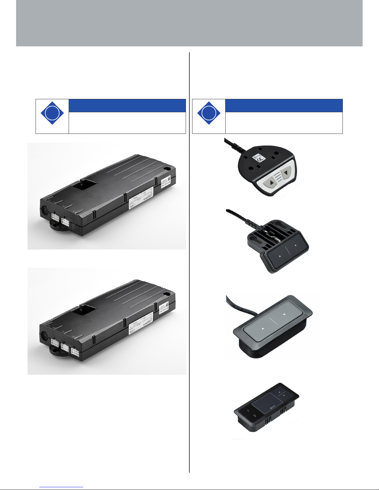
Fig. 4: Various power supply cables 15
Fig. 5: Compact-e-2 control unit 16
Fig. 6: Compact-e-3 control unit 16
Fig. 7: LegaDrive Basic handset 16
Fig. 8: LegaDrive Touch Basic handset 16
Fig. 9: LegaDrive Touch Basic Inlay handset 16
Fig. 10: LegaDrive Touch Inlay handset 16
Fig. 11: LegaDrive Touch Comfort handset 17
Fig. 12: Remote handset Basic 17
Fig. 13: Receiver module for remote handsets 17
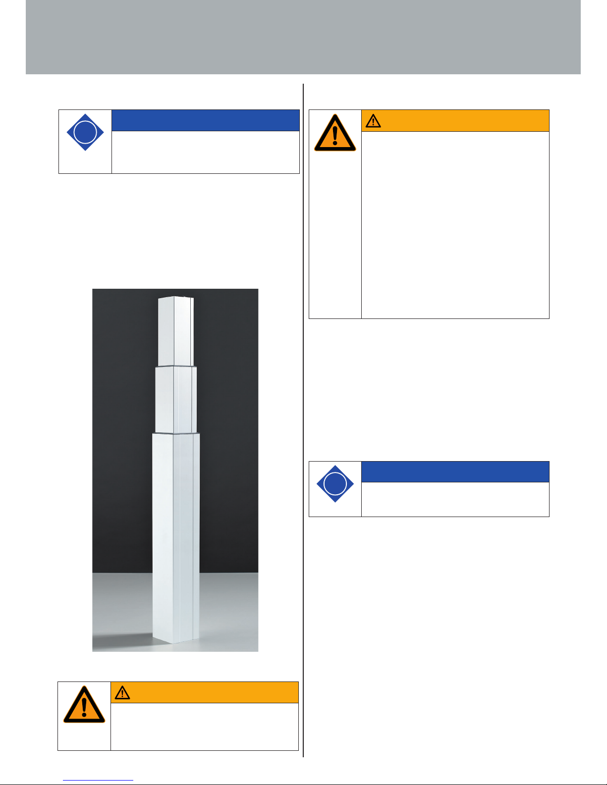
Fig. 14: Lifting column protective enclosure 18
Fig. 15: Attaching lifting column (viewed from below)
to example skid 20
Fig. 16: Attaching lifting column (viewed from above)
to example desk 20
Fig. 17: Fixing points on control unit 21
Fig. 18: LegaDrive Basic handset 21
Fig. 19: Attaching LegaDrive Basic handset to
example desk 21
Fig. 20: LegaDrive Touch Basic handset 22
Fig. 21: Attaching LegaDrive Touch Basic handset to
example desk 22
Fig. 22: LegaDrive Touch Basic Inlay handset 22
Fig. 23: Cut out for installing LegaDrive Touch Basic Inlay
handset with rubber fins 22
Fig. 24: Attaching LegaDrive Touch Basic Inlay handset to
example desk 22
Fig. 25: LegaDrive Touch Inlay handset 23
Fig. 26: Cut out for installing LegaDrive Touch Inlay handset
with rubber fins 23
Fig. 27: Attaching LegaDrive Touch Inlay handset to
example desk 23
Fig. 28: LegaDrive Touch Comfort handset 23
Fig. 29: Position for installing LegaDrive Touch Comfort handset
24
Fig. 30: Position of screw holes for installing LegaDrive Touch
Comfort handset 24
Fig. 31: Attaching LegaDrive Touch Comfort handset to
example desk 24
Fig. 32: Pressing the control panel to automatically extend it 25
Fig. 33: Lifting and pushing the control panel to retract it 25
Fig. 34: Cable loop of 10 cm min. for the push-to-open feature
25
Fig. 35: Control panel detached from above from its anchorage
25
Fig. 36: Spring end hooked into the lug below the slide 25
Fig. 37: Pushing the control panel into the slide 25
Fig. 38: Remote handset Basic 26
Fig. 39: Inserting / replacing the battery Button cell CR 2032 26
Fig. 40: Installing the remote handset Basic 26
Fig. 41: Sockets on control unit 27
Fig. 42: Sockets on control unit 28
Fig. 43: Sockets on control unit 29
Fig. 44: Remote receiver 29
Fig. 45: Battery change 29
Fig. 46: Sockets on control unit 29
Fig. 47: Example configuration 30
Fig. 48: Display on LegaDrive Touch handset 33
Fig. 49: The key symbol indicates activated
display lock 33
Fig. 50: The LegaDrive Touch Comfort handset lock is activated
and deactivated by swiping to the left or right 33
Fig. 51: The LegaDrive Touch Inlay handset lock is activated and
deactivated by swiping to the left or right 33
Fig. 52: Container-Stop- / Shelf-Stop-Position 37
Page 5
5
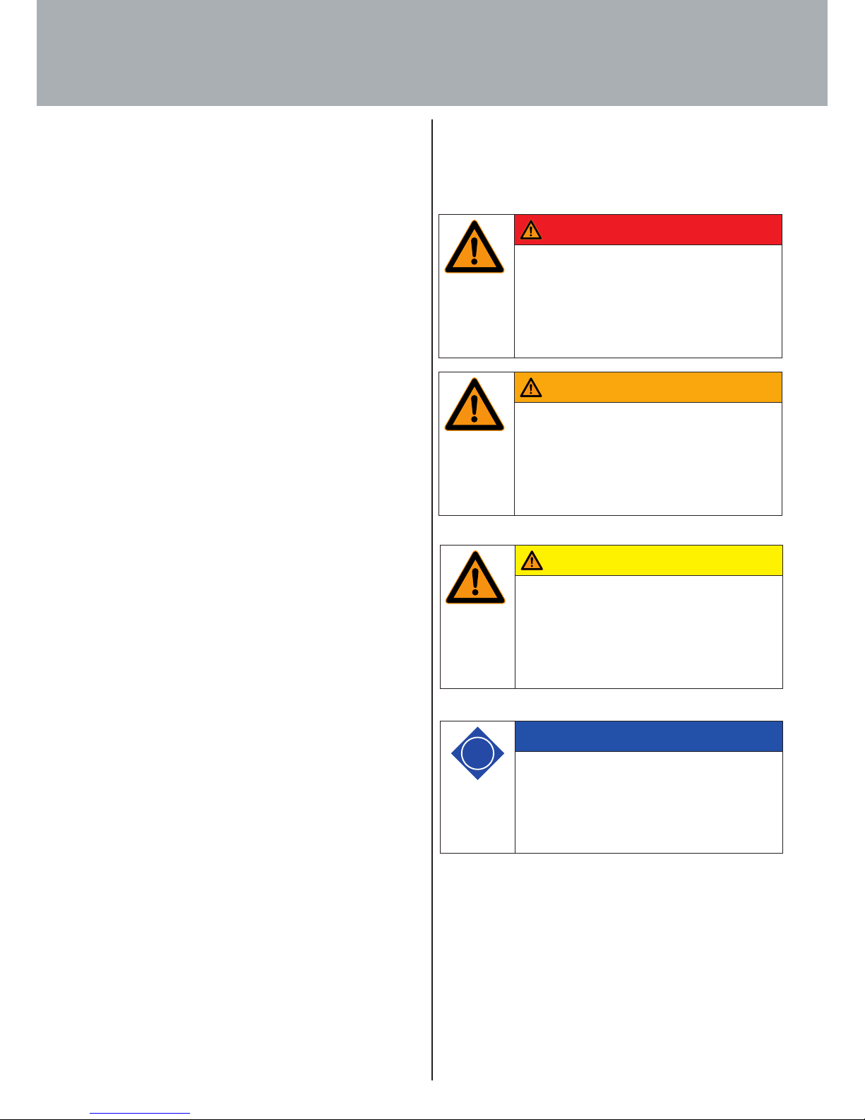
1.1 Information on signs, symbols and markings
The safety advice in the operating and installation instructions is
structured as follows:
These operating and installation instructions are intended to
make it easier for you to become familiarised with the lifting
column system and use its capabilities in the proper manner.
These operating and installation instructions contain impor-
tant information on installing the lifting column system safely
and in the proper manner. Following them will help to avoid
hazards, repair costs and down times, enhance reliability and
prolong service life.
Existing national regulations on preventing accidents and on
protecting the environment are also applicable.
These operating and installation instructions must be read
and applied by all persons instructed to carry out work on the
system's components, e.g.:
· Installation
· Operation
· including troubleshooting while working, care, disposal
· Maintenance
· Servicing, inspection, repair and
· Transportation.
1. Introduction
Danger
Danger!
This danger note draws attention to an immedi-
ately dangerous situation that will lead to death
or serious injuries if the safety measures are not
followed.
Warning
Warning!
This danger note draws attention to a potentially
dangerous situation that may lead to death or
serious injuries if the safety measures are not
followed.
Caution
Caution!
This danger note draws attention to a potenti-
ally dangerous situation that may lead to minor
or slight injuries if the safety measures are not
followed.
i
Note
This advice draws attention to potential damage
to property or to a process of particular interest /
importance that may occur if the safety measu-
res are not followed.
Page 6
6
1. Introduction
1.2 Information for the owner
In addition to these operating and installation instructions and
the accident prevention regulations in force in the country of use
or at the place of application, it is also necessary to follow the
recognised code of safe and proper working practice.
Without the manufacturer's consent, the owner of the lifting
column system must not make any changes, additions or modifi-
cations to it that may aect safety.
Components used must meet the technical requirements defined
by the manufacturer.
Only ever deploy trained or instructed personnel and clearly de-
fine personnel responsibilities with regard to operating, servicing
and repair.
i
Note
Always perform a hazard analysis of your fini-
shed product (height adjustable workstation)
so you are able to respond to potential residual
hazards (e.g. in the form of structural measures
or warnings in the
operating instructions and/or safety warnings on
your product).
Page 7
7
2.2 Foreseeable incorrect use
The situations above describe some of the residual hazards which,
despite being impermissible, may occur and harm the health of
sta.
The owner must observe the safety requirements defined in the
German Ordinance on Industrial Safety and Health (Betriebssi-
cherheitsverordnung).
2.1 Intended use
This lifting column system is only intended for installing and then
being used as an electrically height adjustable sitting / standing
workstation in accordance with EN 527 in indoor commercial en-
vironments. This means the lifting column system is only intended
for this purpose.
Any other use beyond this, e.g. outside the technical specifica-
tions (see Section 4.1), is deemed to be incorrect use.
In this context, always follow Section 3 "Safety".
Intended use also includes following the operating, servicing and
maintenance conditions prescribed by the manufacturer.
Unauthorised changes to the lifting column system will result in
the loss of product liability and liability on the part of the manu-
facturer for resultant damage.
Any other use beyond this is deemed to be non-intended use. The
manufacturer shall not be liable for any damage this causes, with
the risk involved being borne solely by the user.
2. General
Warning
Warning!
This danger note draws attention to a potentially
dangerous situation that may lead to death or
serious injuries if the safety measures are not
followed.
i
Note
Do not use the lifting column system in a private
environment but only in commercial premises.
Warning
Hazards may occur if the system is used incor-
rectly!
The following situations in particular are
deemed to be foreseeable hazardous situations:
· Persons may manipulate protective guards.
· Persons may remove separating protective
guards and then put the lifting column system
into operation.
· Persons may use the desk support in private
envirionments.
· Persons may use the desk support for lifting
persons or loads.
· Persons could incorrectly install the LegaDrive
lifting column and use it in pull direction.
· Persons may perform servicing or troubleshoo-
ting work etc. on the desk support without
disconnecting the lifting column system from
the power supply.
· Persons may make adjustments to the desk
support despite the presence of other persons
in the hazard zone.
· Persons may ignore the desk support's maxi-
mum loading capacity.
· Persons may open, remove or damage enclosu-
res of system components.
Page 8
8
i
Note
Further variants can be found in the Hettich
catalogue
If used, the following components are part of the
overall system:
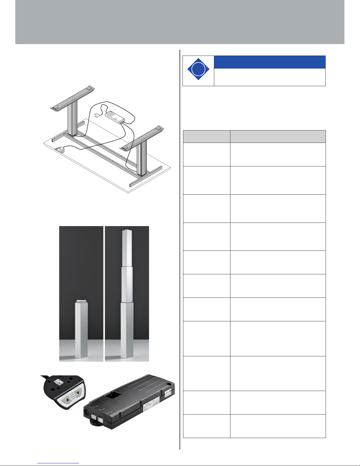
2.3 Package contents
Depending on requirements, the following components may be
used for installing an electrically height adjustable workstation.
Fig. 1: Example showing overall product
The following components (including cabling) are available for
the system:
Fig. 2: Lifting column (here: moved in and out)
Fig. 3: Example of a handset and a control unit
2. General
Component Description
Lifting column
LegaDrive Q 90 A
LegaDrive power-assisted lifting column.
Square 90 mm x 90 mm.
Anodised aluminium.
Control unit
LegaDrive
Compact-e-2-EU
Compact-e-2-EU control unit for
LegaDrive.
For 2 LegaDrive lifting columns and mains
voltage 230V/50Hz.
Control unit
LegaDrive
Compact-e-3-EU
Compact-e-3-EU control unit for
LegaDrive.
For up to 3 LegaDrive lifting columns and
mains voltage 230V/50Hz.
Control unit
LegaDrive
Compact-e-3-US
Compact-e-3-US control unit for
LegaDrive.
For up to 3 LegaDrive lifting columns and
mains voltage 120V/60Hz.
Handset
LegaDrive Basic
Handset Basic for LegaDrive.
With up and down buttons.
Installation under desk top.
Handset
LegaDrive Touch
Basic
Handset Touch Basic for LegaDrive.
With up and down buttons.
Installation under desk top.
Handset
LegaDrive Touch
Basic Inlay
Handset Touch Basic Inlay for LegaDrive.
With up and down buttons.
Recessed in desk top.
Handset
LegaDrive Touch
Inlay
Handset Touch Inlay for LegaDrive.
With up and down buttons and memory
function.
With digital display for height setting.
Recessed in desk top.
Handset
LegaDrive Touch
Comfort
Handset Touch Comfort for LegaDrive.
With up and down buttons and memory
function.
With digital display for height setting.
Installation under desk top.
Power supply cable
LegaDrive CH
Power supply cable for LegaDrive type J.
Mainly used in Switzerland.
Power supply cable
LegaDrive DK
Power supply cable for LegaDrive type K.
Mainly used in Denmark.
M1
HS
M2
M3
Page 9
9
Power supply cable
LegaDrive EU
Power supply cable for LegaDrive type F.
"SchuKo" plug, mainly used in
Germany, Austria, BeNeLux, France,
Spain, Sweden, Norway, Finland etc.
Power supply cable
LegaDrive IT
Power supply cable for LegaDrive type L.
Mainly used in Italy.
Power supply cable
LegaDrive UK
Power supply cable for LegaDrive type G.
Mainly used in the United Kingdom.
Power supply cable
LegaDrive NA
Power supply cable for LegaDrive type B.
Mainly used in the USA, Canada, Mexico
etc.
2.4 Liability
Defects must only be rectified by competent personnel.
The manufacturer's liability is restricted to damage caused
while using the system in the intended manner. The
manufacturer shall not be liable for safety defects not yet
identifiable on the basis of the current state of the art.
Failure to observe
· safety advice for operating personnel
· advice on particular hazards
· the ban on unauthorised modifications and changes
· ban on using components not approved by the
manufacturer
shall rule out any liability on the part of the manufacturer for the
consequences.
2. General
Page 10
10
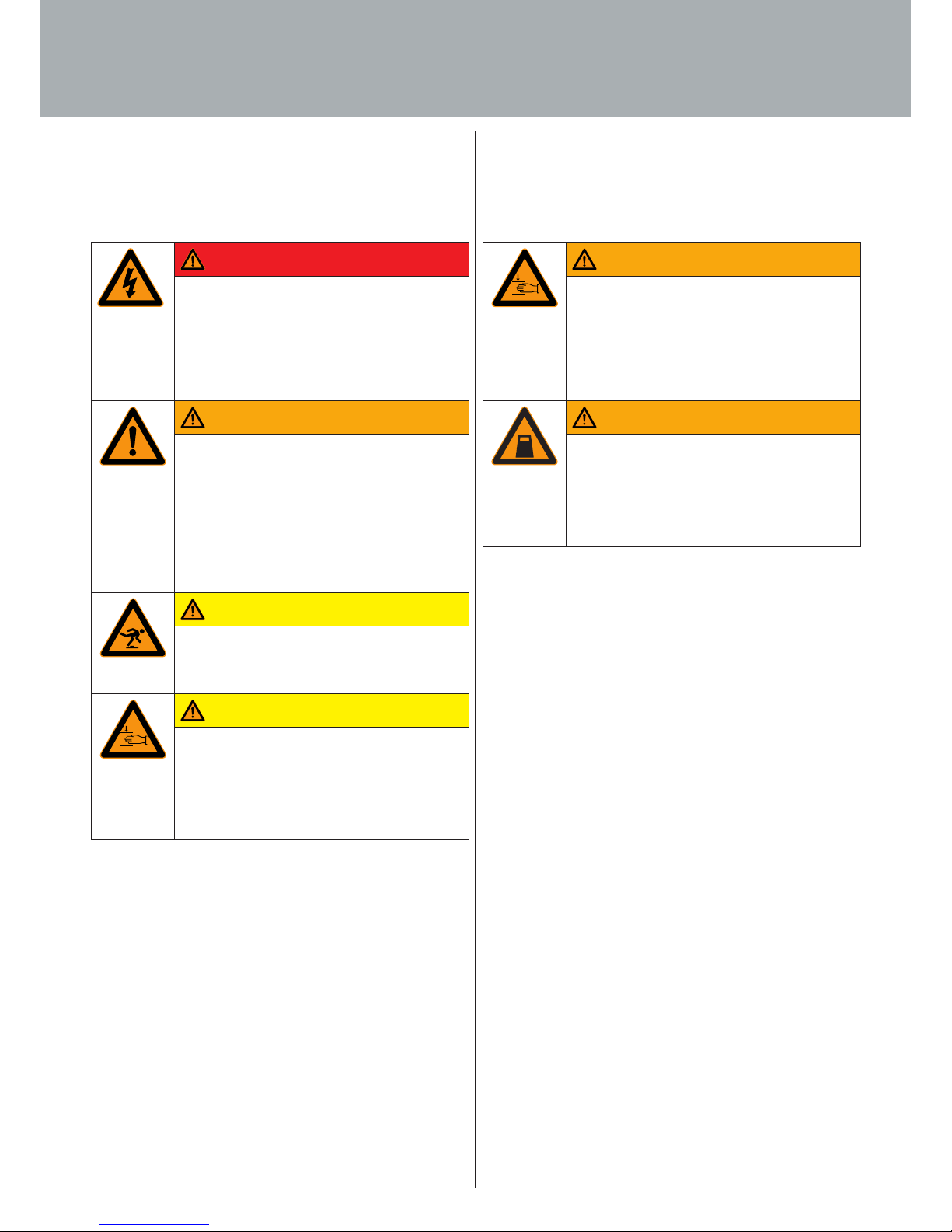
The following hazard markings must be axed directly to the
desk where they are visible:
The following hazard zone markings are used in the operating
and installation instructions (in accordance with Technical Rule
for Working Places ASR A1.3):
3. Safety
Danger
Danger from electric shock!
Working on live components in the improper
manner presents a danger to life!
Work on electrical equipment must only be car-
ried out by authorised electricians!
Warning
Risk of injury!
The lifting columns pose a risk of injury when
they are moving. Before attempting any work,
disconnect the lifting column system from power
supply and take action to prevent the power
supply cable from being plugged back in unin-
tentionally!
Caution
Tripping hazard!
The desk support and power supply cable pose of
risk of injury from tripping over.
Caution
Hand injuries!
Hand could be crushed or otherwise injured.
Never reach into moving parts!
Only set the desk support in motion when there
is nobody in the hazard zone!
Warning
Danger of crushing!
Do not position any objects of parts of the body
below the desk support or between the cross
members. Failure to observe this warning may
result in serious injuries or death!
max.
KG
Warning
Danger of crushing!
Do not overload!
Only load the desk support up to the maximum
intended load. Overloading may result in breaka-
ge and serious injuries!
Page 11
11
3.2 Safety advice for operating personnel
The desk support must only be put into operation in a fully ins-
talled and operational state.
The generally recognised code of occupational health and safety
as well as accident prevention regulations must be observed.
The desk support must only be operated if all protective guards
and safety-related equipment, e.g. protective claddings or enclo-
sures, are in working order and undamaged.
On putting the system into operation, the operator must make
sure that all safety equipment and protective guards as well as
the controls are in correct working order and free of damage.
Work on the desk support must only be carried out by instruc-
ted, skilled personnel. Only skilled personnel who have received
training or instruction must be deployed.
Immediately leave the area around the desk if it starts moving
unintentionally. Immediately disconnect the lifting column
system LegaDrive from the power supply. Have the desk support
repaired by a specialised company. Only put the desk support
back into operation after it has been repaired.
Immediately take the desk support out of operation if you notice
anything unusual (noises, fumes, smoke etc.) at the desk support.
Immediately disconnect the lifting column system LegaDrive from
the power supply. Have the desk support repaired by a specialised
company. Only put the desk support back into operation after it
has been repaired.
Immediately take the desk support out of operation if the safety
devices (e.g. up/down switch) are not working properly.
Only operate the desk support in a commercial environment.
Do not use the desk support on an uneven standing surface. It
could tip over.
3.1 Safety advice for the user company
All persons entrusted with operating the lifting column system
LegaDrive (include line managers) must familiarise themselves
with the section on "Safety". The safety advice must be followed.
The lifting column system LegaDrive must only be operated if
it is in proper working order. The user company will issue clear
responsibilities, e.g. for servicing, cleaning or repair, and ensure
that the persons carrying out this type of work have received the
training necessary for it.
The safety regulations and employers' liability insurance associ-
ation regulations applicable in the owner's country must also be
observed. Refrain from any work that adversely aects operating
safety.
The operating personnel will check the desk support for changes
or malfunctions, report such to the safety ocer responsible and,
if necessary, take this product out of operation.
Only appropriate tools must be used for the work that needs to
be done; remove tools after completing work.
3. Safety
Warning
Never
· operate the desk support if there is anyone in
the hazard zone.
· operate the desk support in a private environ-
ment.
· remove covers or enclosures and take protective
guards out of operation.
· continue operating the desk support if changes
occur that adversely aect safety.
· manipulate or circumvent protective guards.
· use for normal operation without protective
guards in place.
Page 12

12
Do not make any structural changes to the lifting column system.
Observe the lifting column system‘s maximum ON time.
Only replace faulty components with new, genuine parts from
the manufacturer. When doing so, follow these operating and
installation instructions.
Make sure operating consumables and auxiliary substances as
well as replaced parts are disposed of safely and in an environ-
ment-friendly manner.
3.4 Noise
The lifting column system‘s A-weighted equivalent continuous
sound level is less than 60 dB (A).
3.5 Hazards from electrical energy
Only connect the lifting column system to the power supply after
it has been completely installed.
Regularly check the desk support‘s electrical equipment in ac-
cordance with national regulations (in Germany, the regulations
on preventing accidents).
No not use any cable with damaged insulation. You could get
an electric shock. Immediately instruct a specialised company to
replace damaged cables with undamaged ones.
Do not route the power supply cables near sources of heat. Ex-
posure to heat could damage the cable. A fire could be started or
you could get an electric shock.
Disconnect the lifting column system from the power supply if
it is to be left unused for a prolonged period or when it is not in
use.
Observe the lifting column system's ON time
of 10 %. This means, for example, that 1 minute of continuous
operation must be followed by a pause of 9 minutes or that
operation for a maximum of 2 minutes must be followed by an
18 minute pause.
No not load the desk support beyond the permissible weight limit
(see "Technical Specifications" in Section 4.1).
Allow a distance of at least 25 mm for adjacent elements moving
in relation to each other. This applies to the entire range of travel.
3.3 Safety advice for maintenance work
Please make sure that the product is always in perfect condition
and, if necessary, have it checked at regular intervals by skilled
personnel.
Do not perform any repairs to the desk or components yourself.
Maintenance work must only be performed by the manufacturer‘s
skilled personnel or under the manufacturer‘s supervision.
If the lifting column system is completely shut down for servicing
and repair work, it must be prevented from switching back on
unexpectedly.
For maintenance measures use tools that are appropriate for the
work involved.
Servicing and repair work must only be carried out by the owner‘s
skilled personnel.
Work on electrical components must only be carried out by a
qualified electrician or by instructed persons under the direction
and supervision of a qualified electrician in accordance with the
rules of electrical engineering.
If safety devices need removing for servicing and repair work,
they must be refitted and checked as soon the work has been
completed.
Always tighten screw connections that have come loose during
servicing and repair work.
3. Safety
Page 13
13
3.6 Particular hazard spots
When adjusting the desk support, make sure there is nobody in
the vicinity. They could be injured.
When setting up the desk support, make sure it is unable to col-
lide with anything (e.g. sloping roofs, structural situation, mobile
pedestals, wastepaper baskets etc.) in any position to which is
can be moved.
Also make sure it cannot collide with objects
(e.g. IT equipment) on the desk either.
Allow a safety distance at the side of at least 25 mm to any other
item of furniture.
Make sure that cables employed are of sucient length for safe
use throughout the entire range of travel.
3.7 Residual risk
The lifting column system reflects the state of the art and is built
in accordance with recognised safety regulations. All the same,
the user or third parties may still be exposed to hazards.
It must only be used:
· for the intended purpose and
· in an absolutely safe state.
3. Safety
Warning
Risk of injury!
Never remove safety devices or render them inef-
fective by making changes to the desk support!
Malfunctions presenting a safety risk must be
rectified without delay!
Before attempting any servicing and cleaning
work, switch the lifting column system o and
prevent it from switching back on again!
Caution
Residual hazards!
Handling the lifting column system involves resi-
dual hazards that could not be limited by design
measures.
Pay attention to the residual hazards described
in these operating and installation instructions
as well as in the end product's documentation!
i
Note
Always perform a hazard analysis of your fini-
shed product (height adjustable workstation)
so you are able to respond to potential residual
hazards (e.g. in the form of structural measures
or warnings in the operating instructions and/or
safety warnings on
your product).
Warning
Risk of injury!
Make sure that no unauthorised persons (e.g.
small children, persons under the influence of
medication etc.) play with or handle your pro-
duct and the lifting column system.
Page 14
14
3.8 Training/instruction
As owner, you are obliged to inform and instruct the
operating personnel in respect of applicable legal and
accident prevention regulations as well as the safety devices
fitted. In this context, bear in mind the varying specialised quali-
fications of your sta.
3.9 Personnel qualification
Only persons over the age of 16 are allowed to set up and work
on the desk support.
The fitters must have read and understood the operating and
installation instructions.
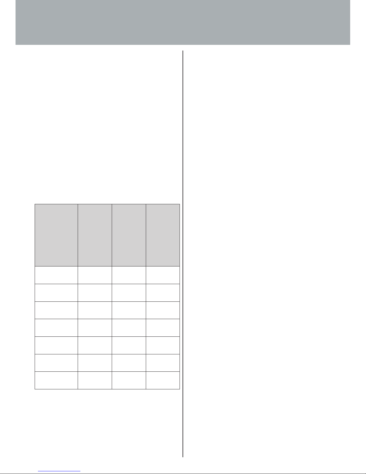
3. Safety
Persons
Activity
Specially
trained
personnel
Instructed
operating
personnel
Instructed
persons with
specialised
training
(mechanical /
electrical
engineering)
Handling
X
Start-up
X
Setting up,
setting
X X
Operation
X
Servicing
X
Troubleshooting
X X
Destruction/
recycling
X
Page 15
15
4.2 Controls
The lifting column system's controls are described below.
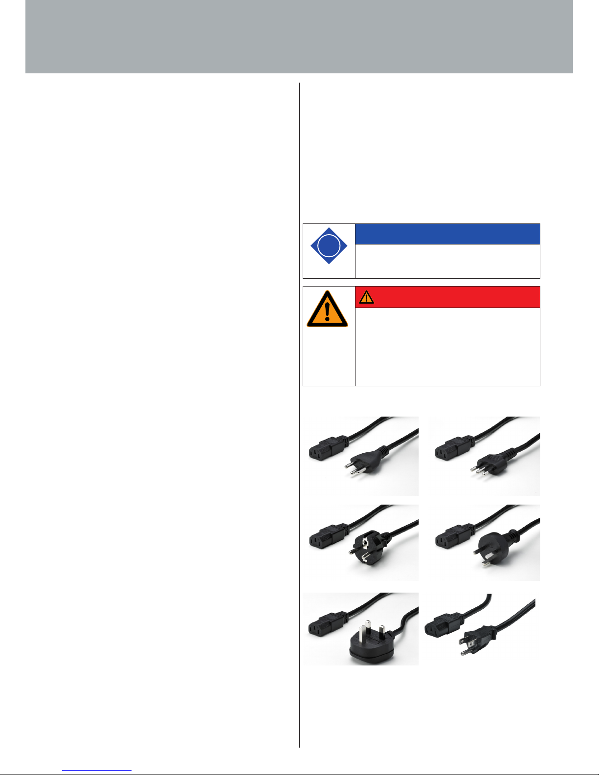
4.2.1 Power supply cable
Depending on place of use, the power supply cables are available
in dierent versions.
Fig. 4: Various power supply cables
4.1 Technical specifications
Designation: Lifting column system for an electri-
cally height adjustable workstation
Type: LegaDrive
Place of installation: Indoors (commercial)
Power supply: 230 V; 50 Hz / 120 V; 60 Hz
(depending on the control unit used)
Minimum height: approx. 575 mm
Maximum height: approx. 1250 mm
max. Loading capacity
per column: 80 kg, dynamic
Desk use: - for
2 columns, dynamic load of
120 kg,
- for 3 columns, dynamic load of
120 kg
- for each additional column +40 kg
(Example: Desk with 5 columns
120 kg + 40 kg + 40 kg = 200 kg)
(in each at the centre above the desk
columns)
Number of lifting columns for
Compact-e-2 control unit:
2 columns
Compact-e-3 control unit:
1, 2 or 3 columns
Max. speed: 40 mm/s
Usage cycle: 10 %
(2 min. of continuous operation /
18 min. out of operation)
Ambient temperature
during operation: 5 °C to 40 °C
Storage /
transportation temperature: -40 °C to 70 °C
Air humidity
during operation
(non condensing): 5 % to 85 %
Max. noise level: 60 dB (A)
Protection class: IP 20
Unauthorised changes and modifications to the lifting column
system are not permitted for safety reasons and rule out any
liability on the part of the manufacturer for any resultant
damage.
4. Description of the product
Danger
Danger from electric shock!
Working on live components in the improper
manner presents a danger to life!
Work on electrical equipment must only be car-
ried out by authorised electricians!
i
Note
Please pay attention to the information under
"Package contents".
Page 16
16
4.2.3 Handset
The handset is used for controlling the lifting column system.
Depending on the scope of functions, the handsets are available
in dierent versions.
Fig. 7: LegaDrive Basic handset
Fig. 8: LegaDrive Touch Basic handset
Fig. 9: LegaDrive Touch Basic Inlay handset
Fig. 10: LegaDrive Touch Inlay handset
4.2.2 Control unit
Depending on the number of lifting columns needed and the
desired mains voltage, the control units are available in dierent
versions.
Fig. 5: Compact-e-2 control unit
Fig. 6: Compact-e-3 control unit
i
Note
Please pay attention to the information under
"Package contents".
4. Description of the product
i
Note
Please pay attention to the information under
"Package contents".
Page 17

17
Fig. 11: LegaDrive Touch Comfort handset
Remote handsets:
Fig. 12. Remote handset Basic
Fig. 13. Receiver module for remote handsets
4. Description of the product
i
Note
Refer to the following sections for a detailed
description of the functions.
i
Note
Remote handsets muss be firmly attached and
used within sight of the furniture.
Page 18
18
4.3.2 Software related protective guards
The control unit contains the following software related protecti-
ve guards:
· Collision detector ISP (Intelligent System Protection) with
automatic Drive Back functionality (see Section 7.5.7)
· Low speed areas
· ON time monitor
· Safety zone
· Pedestal stop and shelf stop position
· Plug detection
4.3 Protective guards
4.3.1 Mechanical protective guards
Separating protective guards are installed on the lifting column
to protect the operator from mechanical hazards. And insulating
enclosures are installed around the system's electrical compo-
nents to protect the operator from electrical hazards.
Fig. 14: Lifting column protective enclosure
4. Description of the product
Warning
Risk of injury!
The end product may present further, previously
unforeseeable hazards.
Warning
Risk of injury!
Despite a number of software based protective
guards there is still a
risk of getting crushed in exceptional cases as
motor shutdown is not only governed by the
control unit but also by the interaction of the
mechanical and electronic components!
Shutdown sensitivity is also influenced by the
mechanical components, motor and ambient
conditions!
For this reason, the manufacturer cannot entirely
rule out this residual risk and does not accept
any liability!
i
Note
You will find a detailed description of how to use
the listed functions in the following sections.
i
Note
The primary safety function during height adjust-
ment is the dead man's principle with momenta-
ry contact switch.
Page 19
19
5.2 Installation5.1 Transportation
Only move the lifting column / desk support in a dead state (dis-
connect power supply cable from power supply).
During installation
· electrical work must be performed by qualified electrici-
ans,
· mechanical work must be performed by appropriately
skilled persons.
5. Transportation and installation
Warning
Warning!
You could get knocked and crushed while lifting
and transporting the lifting column / desk sup-
port!
Warning
Warning!
While transporting the desk support no persons
or objects must be on the desk or hanging from
it.
Danger
Danger to life from electric current!
The enclosures around the LegaDrive's compo-
nents must not be opened, removed or damaged.
The power supply cable must be unplugged from
the power supply while installing the control
unit!
Page 20
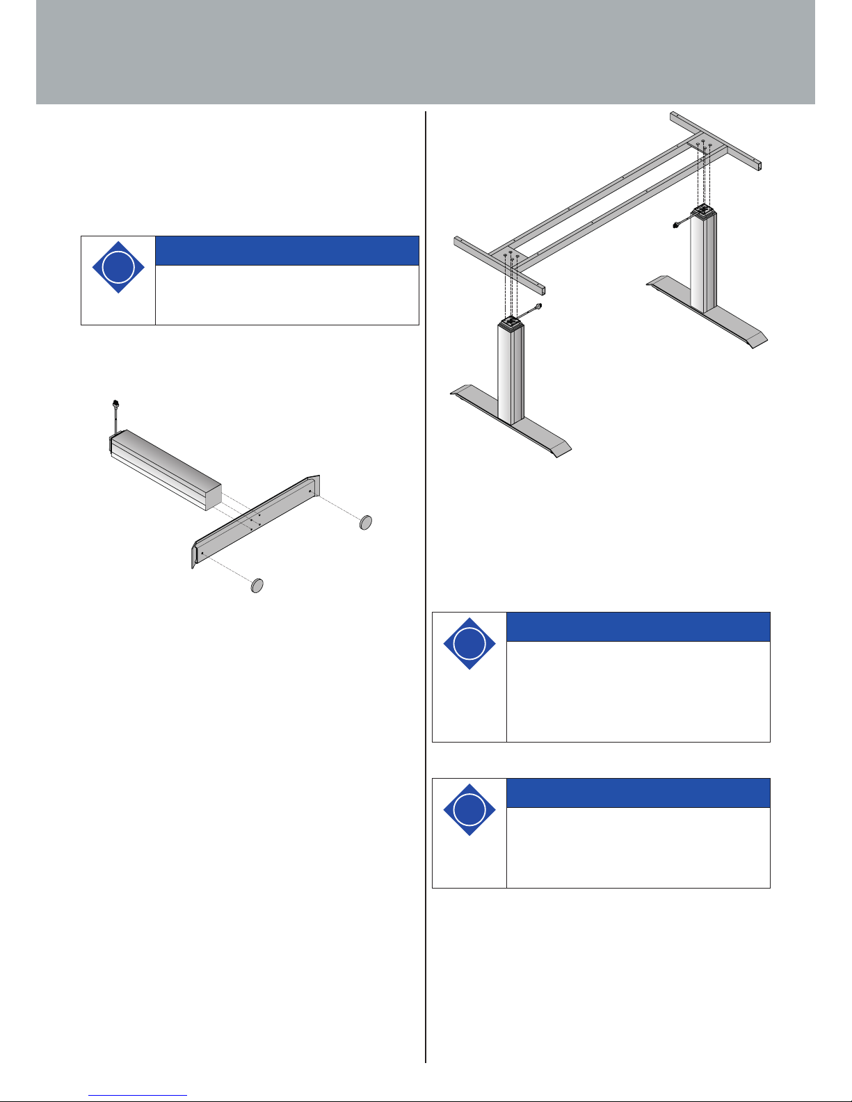
20
Fig. 16. Attaching lifting column (viewed from above)
to example desk top support
4. Now tighten the four screws on each lifting column to
7 Nm max. using a hex driver.
5. The desk top can now be fitted.
5. Transportation and installation
5.2.1 Installing lifting column
Fit the lifting column to the skid and desk top support. To do this
you will need the following tools:
· 1 x hex driver,
· 8 x M6 hexagon socket head screws per lifting column.
To install the lifting column proceed as follows:
1. Connect a skid to a lifting column by means of four hexagon
socket head screws.
Fig. 15. Attaching lifting column (viewed from below) to
example skid
2. Now tighten the four screws on each lifting column to
7 Nm max. using a hex driver.
3. Now connect the requisite lifting columns to the desk top
support by means of four hexagon socket head screws per
lifting column.
i
Note
Use M6 screws of appropriate length, paying
attention to maximum screw length. The screw
must be driven into the column by 8 - 12 mm.
i
Note
An even standing surface with a sucient load
bearing capacity is essential for setting up the
height adjustable desk in a proper and safe
manner. Any unevenness in the standing surface
must be evened out.
i
Note
If lifting columns are replaced in a system, it is
imperative to return the lifting columns to facto-
ry settings first (see Section 7.5.9) and perform a
manual reset (see Section 7.4.4).
Page 21
21
5.2.3 Installing handset
Depending on the handset used, follow the installation instruc-
tions below:
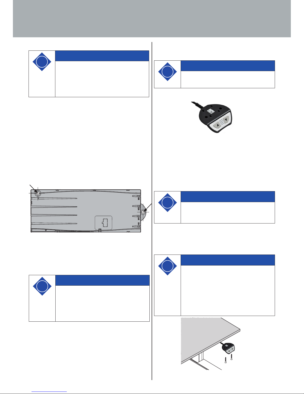
5.2.3.1 Installing LegaDrive Basic handset
Fig. 18: LegaDrive Basic handset
Install the handset under the desk top. To do this you will need
the following tools:
· 1 x screwdriver
· 2 - 4 x screws (depending on the type of handset)
To install the LegaDrive Basic handset under the desk top, pro-
ceed as follows:
1. Unpack handset.
2. Position handset at chosen position under desk top, making
sure that the handset is in easy and convenient reach.
3. Attach the handset with 2 screws.
Fig. 19: Attaching LegaDrive Basic handset to example desk
5.2.2 Installing control unit
Install the control unit underneath the desk top. To do this you
will need the following tools:
· 1 x screwdriver
· 1 x pencil,
· 1 x drill with drill bit (for predrilling).
To install the control unit proceed as follows:
1. Position control unit at chosen position on desk top,
2. Mark drill holes with pencil.
Fig. 17: Fixing points on control unit
3. Predrill these two drilling points.
4. Attach control unit at predrilled points using two screws.
5. Transportation and installation
i
Note
The manufacturer recommends 4 x 20 mm oval
head screws. The length of screw must be appro-
priate for the table top's thickness. Tightening
torque will depend on the table top material but
should not exceed 2 Nm.
i
Note
Dispose of the packaging material in an environ-
mentally friendly manner (plastic film with
plastic waste, cardboard with paper waste)!
i
Note
The following screw types must be used for atta-
ching the LegaDrive Basic handset:
- cylinder head screws
- roundhead screws
- panhead screws
Maximum thread diameter: 5 mm
Maximum head diameter: 9 mm
i
Note
The position of the handset must be selected so
that no damage can occur during operation.
i
Note
Be sure to check that the controller is suited for
the LegaDrive lifting column before assembling
the product.
Refer to the specifications on the type plates.
Observe the mains voltage.
Page 22
22
5. Transportation and installation
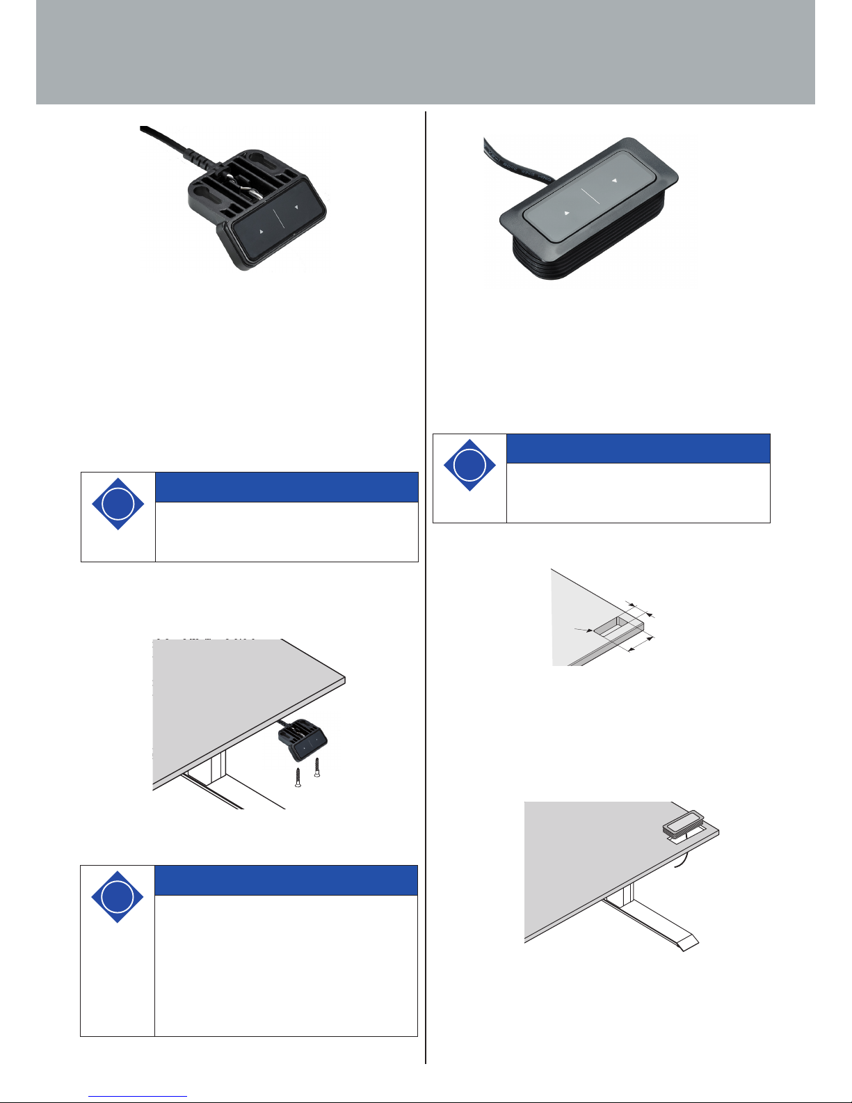
5.2.3.2 Installing LegaDrive Touch Basic handset
Fig. 20: LegaDrive Touch Basic handset
Install the handset under the desk top. To do this you will need
the following tools:
· 1 x screwdriver
· 2 x screws
To install the LegaDrive Touch Basic under the desk top, proceed
as follows:
1. Unpack handset.
2. Position handset at chosen position under desk top, making
sure that the handset is in easy and convenient reach.
3. Attach the handset with 2 screws.
Fig. 21: Attaching LegaDrive Touch Basic handset to example desk
i
Note
Dispose of the packaging material in an environ-
mentally friendly manner (plastic film with
plastic waste, cardboard with paper waste)!
i
Note
The following screw types must be used for atta-
ching the LegaDrive Touch Basic handset:
- cylinder head screws
- roundhead screws
- panhead screws
Maximum thread diameter: 4 mm
Maximum head diameter: 7.3 mm
5.2.3.3 Installing LegaDrive Touch Basic Inlay handset
Fig. 22: LegaDrive Touch Basic Inlay handset
Install the handset at an appropriate position in the desk top.
To install the LegaDrive Touch Basic Inlay handset under the desk
top, proceed as follows:
1. Unpack handset.
2. Drill / cut out an installation hole. The cut out is illustrated
below.
Fig. 23: Cut out for installing LegaDrive Touch Basic Inlay
handset with rubber fins
3. Insert the handset from above into the previously drilled hole
in the desk top. The handset is installed without additional
screws, the rubber fins hold it in position.
Fig. 24. Attaching LegaDrive Touch Basic Inlay handset
to example desk
i
Note
Dispose of the packaging material in an environ-
mentally friendly manner (plastic film with
plastic waste, cardboard with paper waste)!
64,6
26,9
R9
Page 23
23
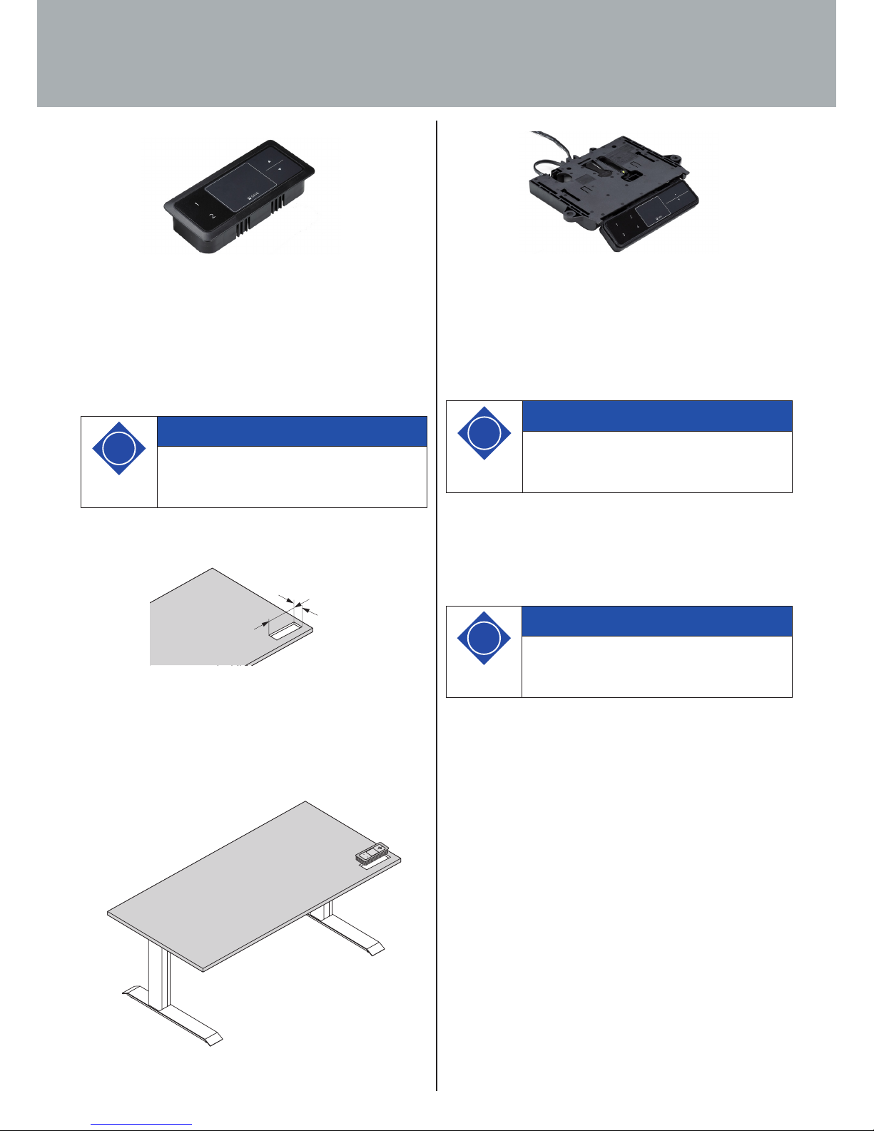
5.2.3.4 Installing LegaDrive Touch Inlay handset
Fig. 25: LegaDrive Touch Inlay handset
Install the handset at an appropriate position in the desk top.
To install the LegaDrive Touch Inlay handset under the desk top,
proceed as follows:
1. Unpack handset.
2. Drill / cut out an installation hole. The cut out is illustrated
below.
Fig. 26: Cut out for installing LegaDrive Touch Inlay handset
with rubber fins
3. Insert the handset from above into the previously drilled hole
in the desk top. The handset is installed without additional
screws, the rubber fins hold it in position.
Fig. 27: Attaching LegaDrive Touch Inlay handset to example desk
i
Note
Dispose of the packaging material in an environ-
mentally friendly manner (plastic film with
plastic waste, cardboard with paper waste)!
39,2 mm
93 mm
5. Transportation and installation
5.2.3.5 Installing LegaDrive Touch Comfort handset
Fig. 28: LegaDrive Touch Comfort handset
Install the handset at an appropriate position underneath the
desk top. To do this you will need the following tools:
· 1 x screwdriver
· 4 x screws
To install the LegaDrive Touch Comfort handset under the desk
top, proceed as follows:
1. Unpack handset.
2. Position handset at chosen position under desk top, making
sure that the handset is in easy and convenient reach. The
front edge of the handset should not project beyond the
edge of the desk so as not to get in the way when you are
working.
i
Note
Please note that the handset has a Push to open
function. Install the handset in the extended
position to make all screw holes accessible.
i
Note
Dispose of the packaging material in an envi-
ronmentally friendly manner (plastic film with
plastic waste, cardboard with paper waste)!
Page 24
24
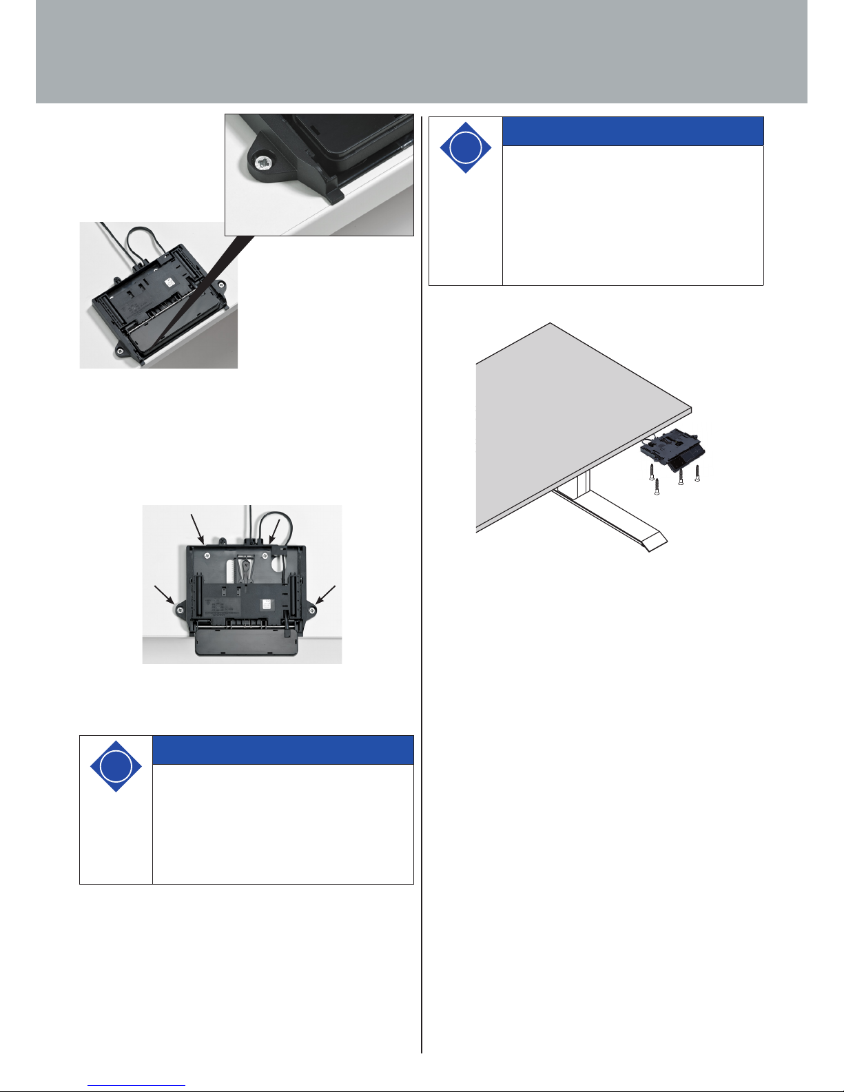
Fig. 29. Position for installing
LegaDrive Touch Comfort handset
3. Attach the handset with 4 screws. To to this, use all 4 screw holes
shown below.
Fig. 30. Position of screw holes for installing LegaDrive Touch
Comfort handset.
5. Transportation and installation
i
Note
The following screw types must be used for atta-
ching the LegaDrive Basic handset:
- cylinder head screws
- roundhead screws
- panhead screws
Maximum thread diameter: 5 mm
Maximum head diameter: 10 mm
Fig. 31. Attaching LegaDrive Touch Comfort handset to example
desk
i
Note
The manufacturer recommends predrilling the
4 screw holes in the desk top. This stops the
mounting plate from twisting when screwing
down the handset and making it dicult for the
control panel to move in and out or even preven-
ting it from doing so.
Page 25
25
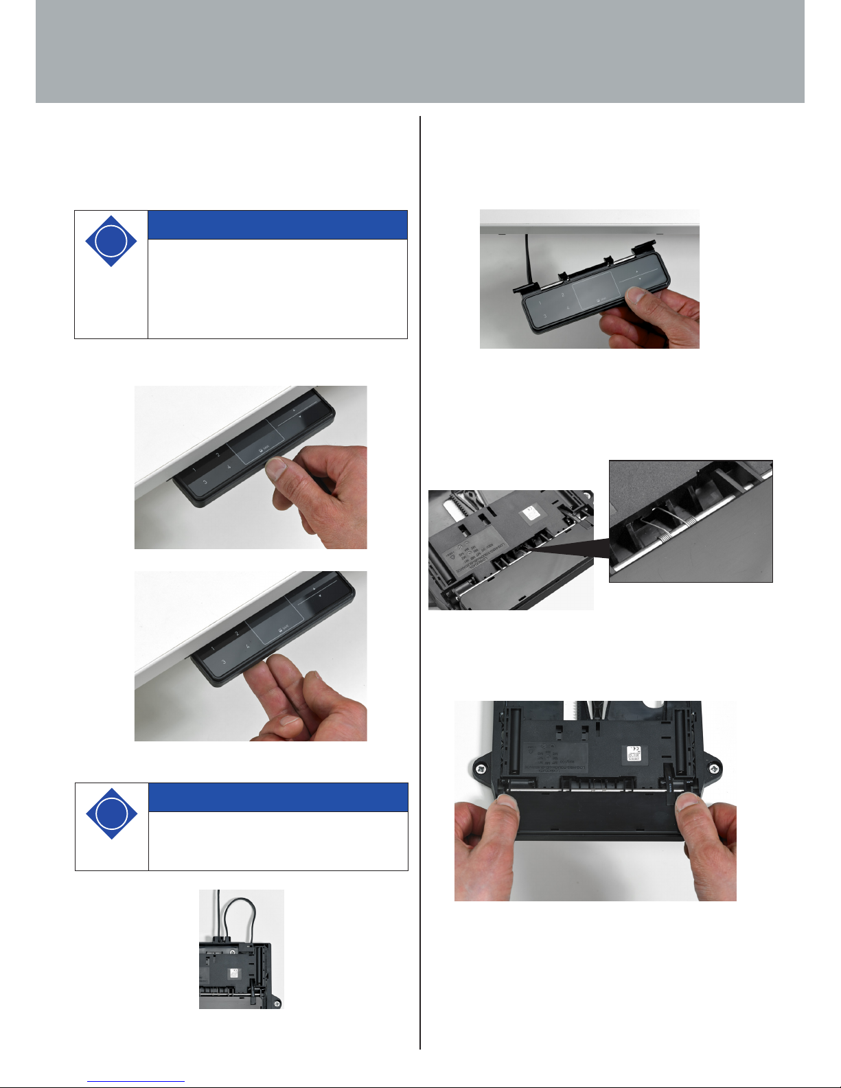
5.2.3.5.2 Notes on the control panel
To prevent damage, the control panel is designed so that it deta-
ches from its anchorage under unusually high pressure (forces
applied from above).
Fig. 35. Control panel detached from above from its anchorage
Follow the steps described below to re-connect the control panel
with the moveable slide:
1. Push the spring ends into the slide seat.
Fig. 36. Spring end hooked into the lug below the slide
2. Push the control panel into the slide by pressing the marked
positions.
Fig. 37. Pushing the control panel into the slide
5.2.3.5.1 Notes on the push-to-open feature
The LegaDrive Touch Comfort manual switch has a push-to-open
feature which automatically extends the control panel when it is
pushed.
Fig. 32. Pressing the control panel to automatically extend it
Fig. 33. Lifting and pushing the control panel to retract it
Fig. 34. Cable loop of 10 cm min. for the push-to-open feature
i
Note
The connecting cable must form a loop of at
least 10 cm to ensure proper operation of the
push-to-open feature (see figure 28).
i
Note
To automatically extend the control panel
(push-to-open feature), it must be pushed in the
retracted position and then released. When ret-
racted the control panel must not be pulled out
to avoid the manual switch from being damaged!
5. Transportation and installation
Page 26
26
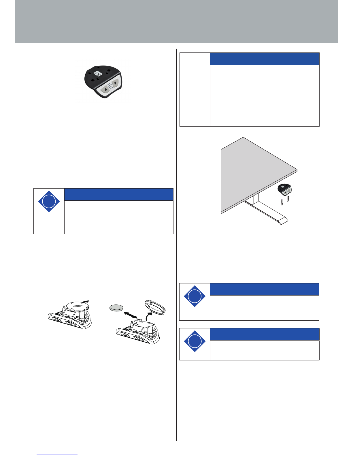
5.2.3.6 Installing the remote handset Basic
Fig. 38. Remote handset Basic
Install the remote handset Basic under the desk top. The fol-
lowing tools are required for the installation:
· 1 x screw driver,
· 2 screws,
Follow the steps described below to install the remote handset
Basic:
1. Unpack the handset.
2. Insert the battery into the handset.
a) To do so, you have to remove the battery cover of the
handset.
b) Then insert the battery. Observe the correct battery pola-
rity.
c) Replace the battery cover on the handset.
Fig. 39. Inserting / replacing the battery Button cell CR 2032
3. Place the handset in the required positon on the piece of
furniture. Make sure that the handset is easily and conve-
niently accessible.
4. Attach the handset using two screws.
Fig. 40. Installing the remote handset Basic
The button cell (CR 2032, included) must be inserted (see section
6.2.2.2) before installing the remote handset Basic.
Observe the correct polarity.
i
Note
Do not install the remote handset Basic unless
the remote receiver has been programmed (see
6.2.2.1).
i
Note
Dispose of the packing material in an environ-
mentally responsible manner (plastic foil in
the plastic waste container, cardboard in the
container for waste paper)!
2.
3.
1.
5. Transportation and installation
Note
The following screw types should be used for
attaching the remote handset Basic:
- Cylinder head screws
- Round-head screws
- Flat-head screws
Max. thread diameter: 4.5 mm
Max. head diameter: 8 mm
i
Note
The remote handset Basic must be firmly at-
tached and used within sight of the furniture.
Page 27
27
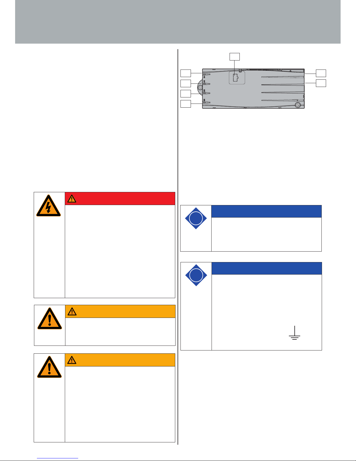
Fig. 41. Sockets on control unit
· M1: Motor/lifting column socket 1
· M2: Motor/lifting column socket 2
· M3: Motor/lifting column socket 3
· D: Logic Connector DATA for sensors and cascading
· HS: Handset socket
· P: Mains power socket
· F: Cable lug for earthing the desk frame
(6.3 mm x 0.8 mm cable lug)
Startup includes those activities that are involved in using the
lifting column system LegaDrive to adjust the height of an elec-
trically height-adjustable workstation. Before the system can be
started up, the following items must have ben installed:
· the control unit,
· the lifting columns for adjusting the height of the desk
top,
· the handset
· Section 6.1 of these operating instructions must be obser-
ved during the initial start-up.
Servicing and maintenance work in specific disciplines (electri-
cal engineering etc.) must only be carried our by skilled persons
trained in that particular discipline.
Observe the following safety advice!
6. Start-up
Warning
Warning!
The enclosures around the LegaDrive's compo-
nents must not be opened, removed or damaged.
Danger
Danger to life!
Working on live components in the improper
manner presents a danger to life!
Work on the electrical equipment must only be
carried out by authorised electricians. The lif-
ting column system LegaDrive must be discon-
nected from the power supply before carrying
out repair and cleaning work!
Disconnect the power supply cable from mains
power supply and take action to prevent it from
being plugged back in unintentionally.
Warning
Warning!
You could get crushed by moving parts if the
lifting column is not shut down.
The lifting column system LegaDrive must be
disconnected from the power supply before
carrying out maintenance and cleaning work!
Disconnect the power supply cable from mains
power supply and take action to prevent it from
being plugged back in unintentionally.
i
Note
It is not permissible to plug products you have
made yourself into the control unit! Only use
manufacturer approved components or the de-
vice may be damaged or irreparably broken!
i
Note
The cable lug (F) next to the mains power socket
is used as a functional earth. The terminal is
used, for example, to dissipate electrostatic
discharges from the electrically height adjustable
workstation. This terminal cannot assume the
function of a protective earth conductor!
The cable lug is marked with the sym-
bol on the top of the enclosure.
M1
M2
M3
HS
P
F
D
Page 28
28
6.2 Start-up prodedure
6.2.1 Plugging in drives/lifting columns
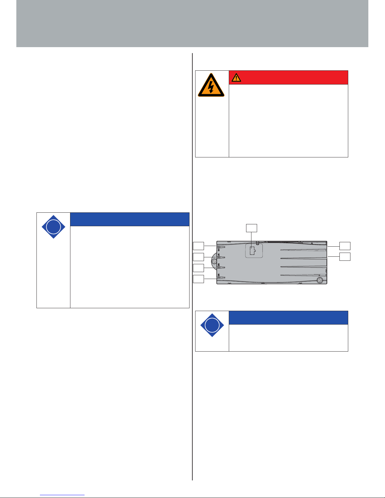
Plug the cables of the lifting columns into the appropriate 8-pin
motor/lifting column sockets (M1 to M3).
Fig. 42. Sockets on control unit
6.1 Starting up for the first time
Before starting up the desk support for the first time, observe the
following:
· Check to make sure the lifting column system LegaDrive
has been installed in accordance with the regulations
specified!
· Check the documentation of the manufacturer of the
desk, whether it has been properly installed.
· Make sure that the desk is placed on a level surface and
aligned horizontally.
· Make sure that moving components can move without
obstruction into the spaces they require and that the safe-
ty distances are observed!
· Make sure the safety devices are in proper working order!
· When commissioning for the first time, a reference run
must be carried out. See chapter 7.4.4 Manual reset.
6. Start-up
i
Note
On start-up, listen for unusual noises and check
to see if there is any heat buildup on adjusting
desk top position.
If this is the case, take the desk support out of
operation.
Have the lifting column system LegaDrive
repaired by a specialised company and only put
the desk support back into operation after it has
been repaired.
Danger
Danger to life!
Danger to life from electric shock!
The power supply cable must only be plugged
in once all components are connected to the
control unit.
The power supply cable must be freely accessible
at all times so that the drive system can be dis-
connected from the mains in an emergency!
i
Note
When plugging in the lifting column cables,
always keep to the order of sequence of M1, M2,
M3 (see Fig. 42)!
M1
M2
M3
HS
P
F
D
Page 29
29
6. Start-up
6.2.2 Plugging in handset
Plug the handset cable into the 7-pin socket.
Fig. 43. Sockets on control unit
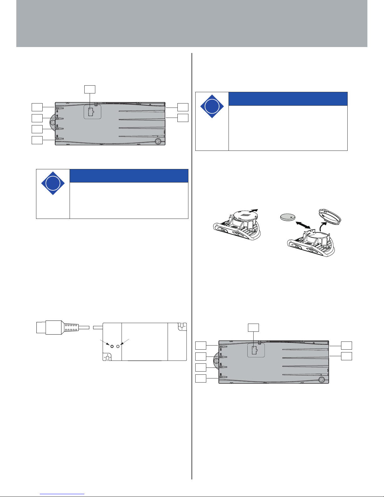
6.2.2.1 Programming the remote handset
The remote receiver must be programmed (taught) to be able to
understand the radiogram from the remote handset. The teach-in
procedure creates an assignment only in the remote receiver.
The distance between the remote handset and the remote recei-
ver should not exceed 0.5 m during the programming.
The remote receiver has a „Teach-in“ button (A) for programming
and a „Control“ LED (B) as an indicator.
B
A
Abb. 44. Remote receiver
Proceed as follows:
1. Briefly press the „Teach-in“ button on the remote receiver.
The „Control“ LED lights up.
2. Immediately send a radio signal (approx. 2 sec.) with the
remote handset. Here you can press the „up“ or „down“
button. The LED switches o briefly.
3. After approx. 8 sec. the teach-in process is terminated auto-
matically or pressing the „up“ or „down“ button again will
immediately end the teach-in process.
i
Note
You can choose between several handsets for the
control unit.
You will find further information on available
handsets under "Package contents".
M1
M2
M3
HS
P
F
D
6.2.2.2 Replacing the battery
The remote handsets are operated with a lithium button cell (CR
2032 included in delivery).
1. Open the battery compartment
2. Remove used button cell
3. Insert new button cell (CR2032)
Pay attention to polarity and avoid soiling
4. Close battery compartment (click into place)
Fig. 45. Battery change
6.2.3 Connecting optional components
If you have an earth cable, attach it to a metal part of the desk
support and to socket F.
Fig. 46. Sockets on control unit
i
Note
Immediate remove used button cells (batteries)
and dispose of them in an environmentally
friendly manner. They must not be discarded
with household rubbish! Replace button cell with
identical type only.
M1
M2
M3
HS
P
F
D
2.
3.
1.
Page 30
30
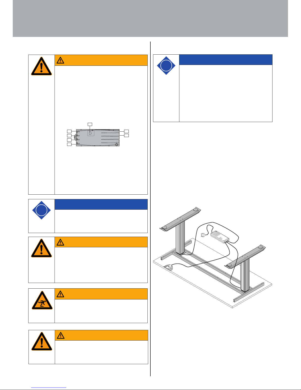
6.3 Overall configuration (example)
In the illustration below you can see the socket assignment for an
example configuration. This example configuration comprises:
· 1: a LegaDrive COMPACT-e-2 type control unit.
· 2: a desk support with two LegaDrive lifting columns
· 3: a LegaDrive Basic type handset
· 4: a LegaDrive EU power supply cable.
Fig. 47. Example configuration
6.2.4 Plugging in power supply cable
6. Start-up
Warning
Warning!
Before plugging in the power supply cable (so-
cket P), check once again to make sure that
· the mains voltage is the same as the mains vol-
tage shown on your control unit's rating plate,
· all components are connected to the right
sockets,
· the earth cable is attached!
The control unit is ready for operation once the
power supply cable has been plugged in.
When installing the power supply, it must be en-
sured that the control unit can be disconnected
from the power supply at any time.
i
Note
A manual reset may be necessary if there is a po-
wer cut or if the power supply cable is unplugged
while adjusting height (see Section 7.4.4).
Warning
Warning!
When laying the cables, make sure they are not
pinched, kinked or stripped of their insulation.
When laying the supply cable, observe the
DIN EN 60335-1 (VDE 0700-1).
Warning
Warning!
When laying the cables make sure that no one
can trip over them (e.g. mains connection cable).
Warning
Warning!
When laying the cables, make sure you allow
sufficient cable length for height adjustment.
i
Note
In this context, also follow the rules and re-
gulations usually applied in the industry, such
as those collated in the "Guideline - Electrical
Installations in Oce Furniture", published by
buero-forum which belongs to bso Verband Büro,
Sitz- und Objektmöbel e.V., the German associ-
ation for oce furniture, seating and contract
furniture.
M1
M2
M3
HS
P
F
D
M1
HS
M2
M3
Page 31
31
7.1 Basic functions
To ensure that the LegaDrive systems operates safely, please
observe the following safety advice:
7. Operation
Warning
Warning!
Make sure that the desk support always moves
correctly and without jerking. If this is not
the case, disconnect the power supply cable
from the mains power and kindly contact the
manufacturer's customer service department.
Danger
Danger to life!
Danger to life from electric shock!
Keep children away from the electrically height
adjustable workstation as well as from the motor
control unit and handset! They could be injured
by voltage.
i
Note
A manual reset may be necessary if there is a po-
wer cut or if the power supply cable is unplugged
while adjusting height (see Section 7.4.4).
i
Note
Unplug the power supply cable from the power
socket in the event of a thunderstorm or prolon-
ged absence! Otherwise the system suer might
damage from mains related voltage surges.
i
Note
The control unit provides a wide range of
functions. The availability of some functions,
however, depends on the handset used.
This section describes the basic functions that
are supported by all handsets intended for the
control unit.
Page 32
32
7.1.2 Downward desk top movement
The function provides an easy way of adjusting the desk top to a
lower position. To do this, proceed as follows:
7.1.1 Upward desk top movement
The function provides an easy way of adjusting the desk top to a
higher position. To do this, proceed as follows:
7. Operation
i
Note
The desk top will continue to move up until you
release the button, or until the highest position
is reached.
i
Note
To reduce power consumption, the control unit
automatically switches to standby mode when
not in use.
The desk top starts to move with a brief lag if
the control unit was in standby mode.
No. Button Function
1.
Press the desk top up button and keep
it pressed until the desk top reaches the
height you want.
i
Note
The desk top will continue to move down until
you release the button, or until the lowest positi-
on is reached.
i
Note
To reduce power consumption, the control unit
automatically switches to standby mode when
not in use.
The desk top starts to move with a brief lag if
the control unit was in standby mode.
No. Button Function
1.
Press the desk top down button and keep
it pressed until the desk top reaches the
height you want.
Page 33

33
7.3. Display lock
The display lock is activated or deactivated by swiping your finger
across the display. The display shows a key symbol on activating
the lock.
Fig. 49. The key symbol indicates activated display lock
Fig. 50. The LegaDrive Touch Comfort handset lock is activated and
deactivated by swiping to the left or right
Fig. 51. The LegaDrive Touch Inlay handset lock is activated and deacti-
vated by swiping to the left or right
7.2. Display functions
The LegaDrive Touch handset has a 4-digit display with optional
decimal point for showing position and information. This is capa-
ble of displaying current desk height, fault messages and menus.
The unit in which desk height is displayed and the decimal point
settings are determined by the motor control parameters.
Fig. 48. Display on LegaDrive Touch handset
7. Operation
i
Note
You can only use the following control unit func-
tions if you have a handset with a display (such
as LegaDrive Touch Inlay or LegaDrive Touch
Comfort).
i
Note
You can only use the following control unit func-
tions if you have a handset with touch functio-
nality and display (such as LegaDrive Touch Inlay
or LegaDrive Touch Comfort).
i
Note
The swiping direction is irrelevant. (see Figures
50 and 51)
i
Note
Be careful only to swipe lightly over the display
without pressing any of the buttons.
i
Note
The display must be active at the time of ac-
tivating / deactivating the lock (e.g. indicating
current height). The display can be activated by
briefly pressing one of the buttons, e..g, the UP
button.
SAVE
SAVE
1 2
3 4
SAVE
1
2
SAVE
Page 34
34
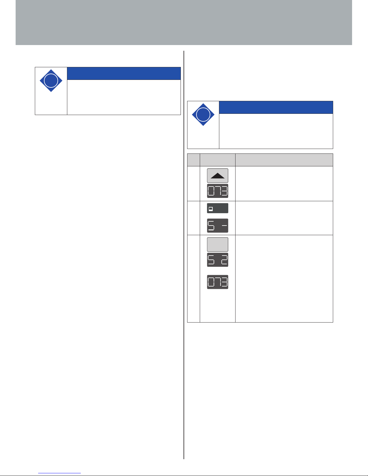
7.4.1 Memorising a desk top position
This function memorises a defined desk top height (one desk top
height can be memorised per memory position button). To memo-
rise a desk top position, proceed as follows:
7.4 Extended functions
i
Note
You can only use the following control unit
functions if you have a handset with memory
position buttons and a memory button.
7. Operation
i
Note
If the control unit is being switched on for the
first time, all memorised positions provide the lo-
west desk top height (bottom desk top position).
No. Button Function
1. Move the desk top to the desk top positi-
on you want.
The display shows this position (e.g. 73
cm).
2.
SAVESAVE
Press the SAVE-button.
The display shows S –.
3.
2
Press the chosen memory position but-
ton (e.g. 2).
The display shows S 2.
The desk top position setting will now
be memorised on the memory position
button selected. You will hear the control
unit click twice and the memorised desk
top position will be displayed after ap-
prox. 2 seconds.
Page 35
35
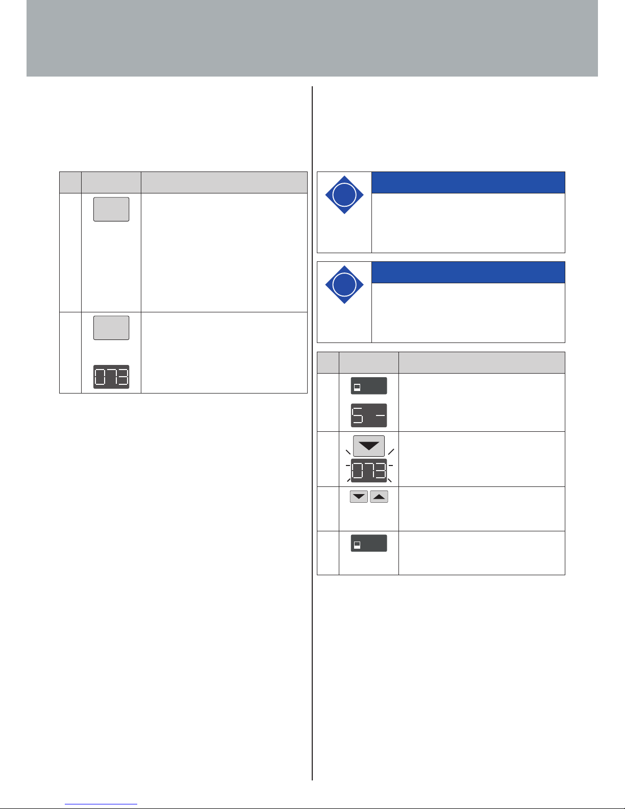
7.4.3 Changing desk top position height display
This function is used for adjusting the height indicated on the
handset display to the desk top's actual height. To make this
adjustment, proceed as follows:
7.4.2 Adjusting desk top to a memorised position
This function lets you move the desk top to a memorised desk top
position. To move to a memorised desk top position, proceed as
follows:
7. Operation
No. Button Function
1.
2
Press the chosen memory position button
(e.g. 2) and keep it pressed. The desk top
will continue to move until the memo-
rised desk top position is reached. If you
let the button go before reaching the
memorised desk top position, the desk
top will stop and the memorised desk top
position will not be reached.
2.
2
Release the memory position button as
soon as the memorised desk top position
has been reached.
The display shows the current (memo-
rised) desk top position.
i
Note
Please note that this setting process does not
alter the desk top's position. Only the indication
on the display changes.
No. Button Function
1.
SAVESAVE
Press the SAVE-button.
The display shows S –.
2.
Press the desk top down button for ap-
prox. 5 seconds (downwards arrow). The
display starts to flash.
3.
Now set the height display using the desk
top down (downwards arrow) or desk top
up button (upwards arrow).
4.
SAVESAVE
Press the SAVE-button.
The height display is now set to the desk
top position entered.
i
Note
This function is only provided for handsets with
integrated display.
Page 36
36
7.5 Software related functions
7.5.1 Low speed areas
While desk top height is being adjusted, this function (low speed
area) automatically slows down the the speed of movement befo-
re the following positions are reached:
· Top and bottom desk top position.
· All memorised positions (e.g. memory position, pedestal
stop position).
7.5.2 ON time monitor
On reaching a defined ON time, the ON time monitor has the
function of shutting down the control unit for a defined period
(e.g. the control unit is automatically shut down for 18 minutes
after 2 minutes of continuous operation).
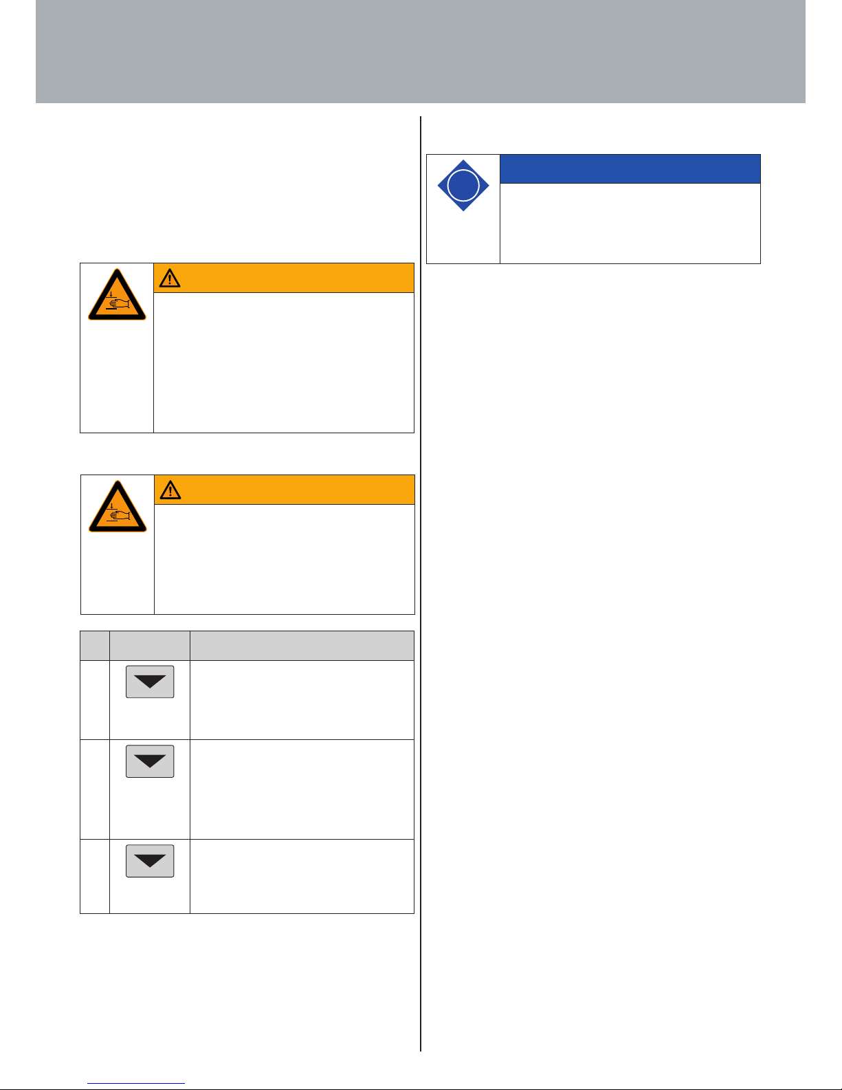
7.4.4 Manual reset
If the actual desk top position no longer matches the desk top
position displayed or if a previously configured control unit is
used at another electrically height adjustable workstation of
identical design, you must calibrate the end position at the bot-
tom most desk top position.
7. Operation
Warning
Warning!
Collision detection (ISP) is not active in any
reset cycle or during end position calibration.
Please realise that you could get crushed!
No. Button Function
1.
Press the desk top down button.
Keep the desk top down button pressed
until the desk top has reached the lowest
position (programmed end position).
2.
Press the desk top down button again
and continue to keep it pressed. After ap-
prox. 5 seconds the desk top will continue
to move down until the bottom most desk
top position is reached.
3.
Release the desk top down button. The
electrically height adjustable workstation
can be used in the normal way again.
i
Note
The control unit is parameterised by software be-
fore leaving the factory. The following functions
can only be used if the control unit is paramete-
rised accordingly.
Warning
Warning!
During the reference run, no furniture parts (e.g.
containers, covers,...) or objects may be within
the adjustment range of the desk. It must be
ensured that the lifting columns can retract
completely. Non-compliance leads to damage to
the lifting column system!
Page 37
37
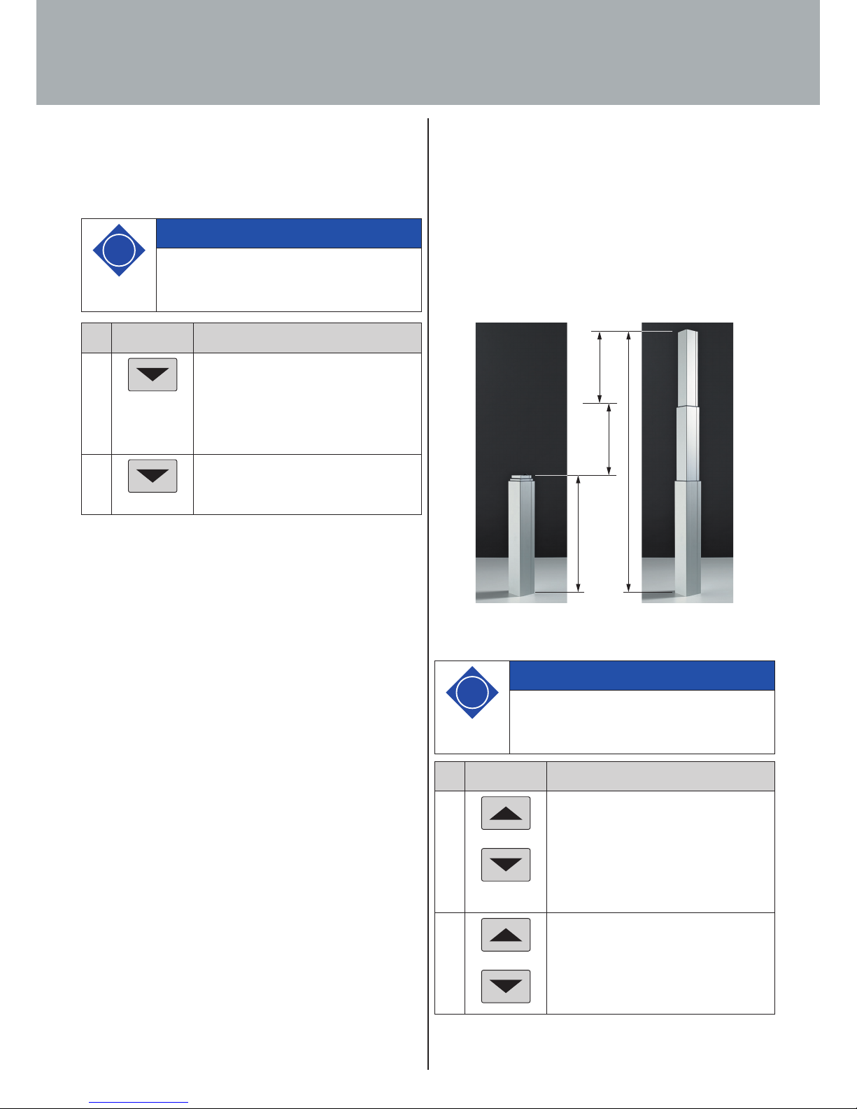
7.5.4 Pedestal stop and shelf stop positions
These two features can be used to limit the desk's travelling ran-
ge (e.g. where a pedestal is standing under the desk). A pedestal
stop position can be set in the lower half of the travelling range,
a shelf stop position in the upper half. If a pedestal stop position
is set, this is used as the new end position; a shelf stop position
functions as a new upper end position for the travelling range.
To memorise a pedestal stop / shelf stop position, proceed as
follows:
Fig.52. Container-Stop- / Shelf-Stop-Position
7.5.3 Safety zone
This function produces a safety stop at a defined desk top positi-
on (configured by software). The safety stop works as follows:
7. Operation
No. Button Function
1.
Press the desk top down button.
Keep the desk top down button pressed
until the desk top stops automatically.
Desk top movement is stopped above the
safety zone.
2.
Press the desk top down button again.
Keep this button pressed until the desk
top reaches the height you want.
i
Note
Desk top positions in safety zones cannot be
memorised.
No. Button Function
1.
or
Move the desk top to the position you
wish to use as the new pedestal stop /
shelf stop position.
To do this, press the desk position down
or desk position up buttons until the
chosen position is reached.
2.
Simultaneously press the desk position
up and desk position down buttons and
keep both buttons pressed for approx.
10 seconds. The control unit clicks twice
once the position has been memorised.
i
Note
These steps must be performed separately for a
pedestal stop position and a shelf stop position.
min.
max.
(max. - min.) /2
(max. - min.) /2
Shelf-
Stop-
Position
Contanier-
Stop-
Position
Page 38
38
7. Operation
To deactivate a pedestal stop / shelf stop position, proceed as
follows:
If you have a handset with display (such as LegaDrive Touch Inlay
or LegaDrive Touch Comfort), proceed as follows:
i
Note
These steps must be performed separately for a
pedestal stop position and a shelf stop position.
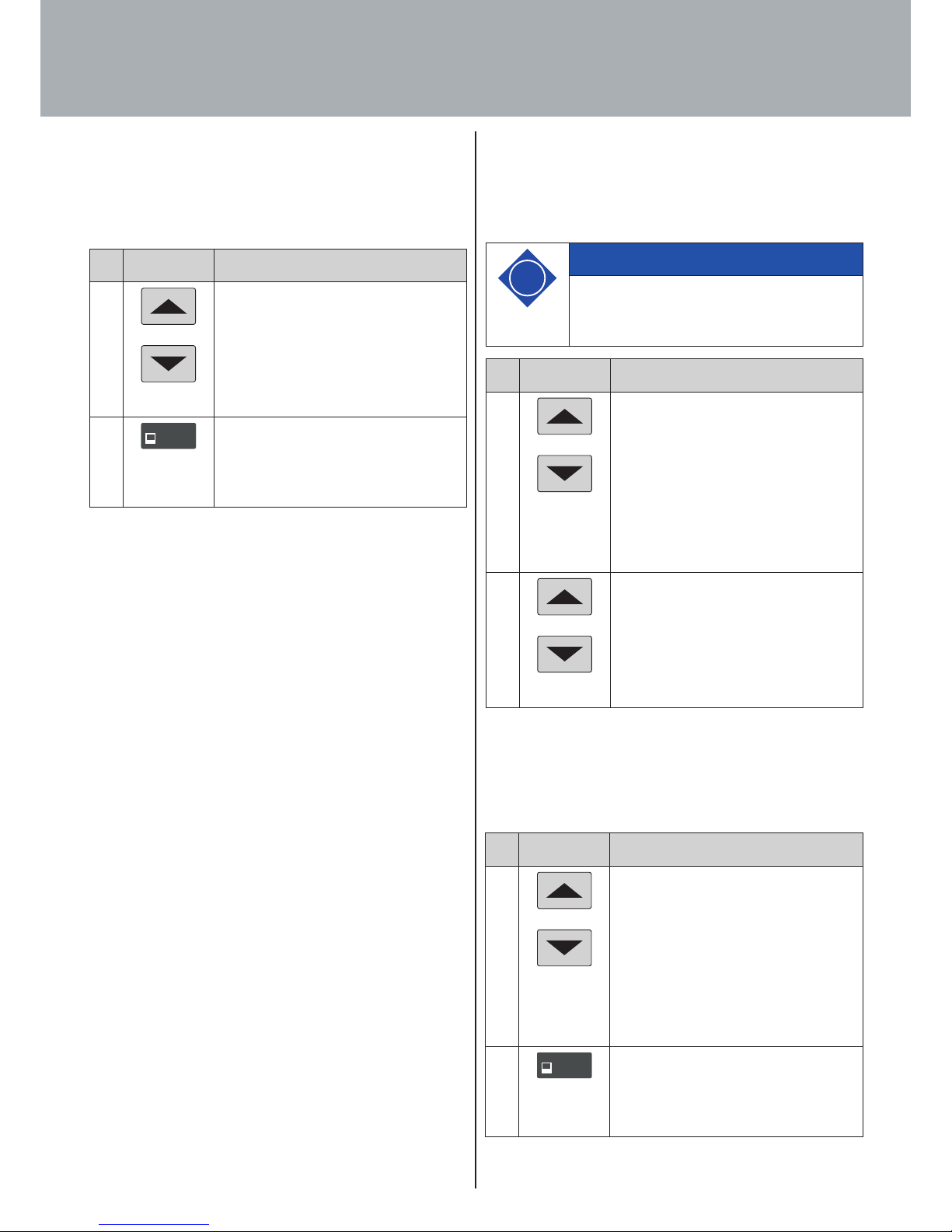
No. Button Function
1.
or
Move the desk top to any position in the
lower half of the travelling range to deac-
tivate the pedestal stop or to any position
in the upper half of the travelling range
to deactivate the shelf stop. To do this,
use the desk position down or desk posi-
tion up buttons until the chosen position
is reached.
2.
Simultaneously press the desk position
up and desk position down buttons and
keep both buttons pressed for approx. 10
seconds.
The control unit clicks once when the
position has been deactivated.
If you have a handset with display (such as LegaDrive Touch Inlay
or LegaDrive Touch Comfort), proceed as follows:
No. Button Function
1.
or
Move the desk top to the position you
wish to use as the new pedestal stop /
shelf stop position.
To do this, press the desk position down
or desk position up buttons until the
chosen position is reached.
2.
SAVESAVE
Press the SAVE-button and keep it
pressed for approx. 10 seconds. The
control unit clicks twice once the position
has been memorised.
No. Button Function
1.
or
Move the desk top to any position in the
lower half of the travel range to deacti-
vate the container stop or to any position
in the upper half of the travel range to
deactivate the shelf stop. To do this, use
the desk position down or desk position
up buttons until the chosen position is
reached.
2.
SAVESAVE
Press the SAVE-button and keep it
pressed for approx. 10 seconds. The
control unit clicks once when the position
has been deactivated.
Page 39
39
7. Operation
7.5.5 Plug detection
The control unit detects whether a lifting column is plugged in at
a specific socket. The control unit also detects whether a lifting
column has been changed.
If a lifting column is missing or has been replaced, the control
unit clicks three times. The display also shows a fault code (see
list of faults in Section 8) if the handset has a display.
A manual reset must be performed to rectify the fault, (see Sec-
tion 7.4.4 for further details).
7.5.6 Auto detect number of drives
Besides plug detection, the control unit can also automatically
detect the number of lifting columns plugged in. This feature is
always active during first startup of the control unit and after
returning the control unit to factory settings (see section 7.5.9).
Lifting columns plugged in after the first startup of the control
unit will not be detected automatically. For changing the estab-
lished configuration the control unit has to be returned to factory
settings.
Possible situations:
· The control unit is being used for the first time
· The control unit has been returned to factory settings
7.5.7 Collision detection (Drive back)
The desk top automatically changes its position by a defined dis-
tance in the opposite direction after triggering a safety function
(through collision detection ISP or optional accessory, e.g. crush
guard). This prevent parts of the body from being permanently
trapped.
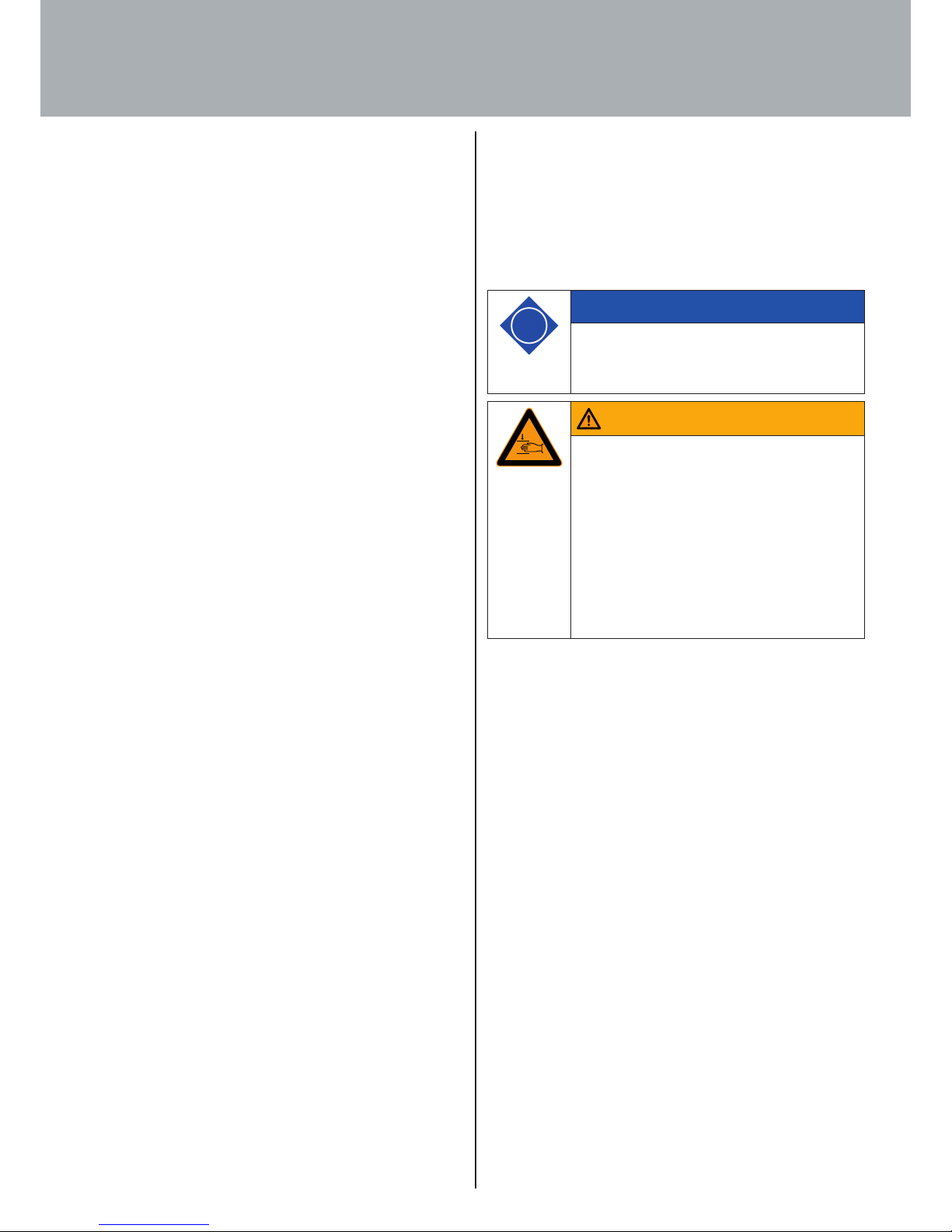
i
Note
The drive back function is only active if a collisi-
on detector (ISP or optional accessory, e.g. switch
or crush guard) is available.
Warning
Warning!
In spite of ISP collision detection there is still
a risk of getting crushed in exceptional cases
as motor shutdown is not only governed by the
control unit but also by the interaction of all
components of the electrically height adjustab-
le workstation! Deactivation sensitivity is also
influenced by the mechanical components, motor
and ambient conditions!
Page 40
40
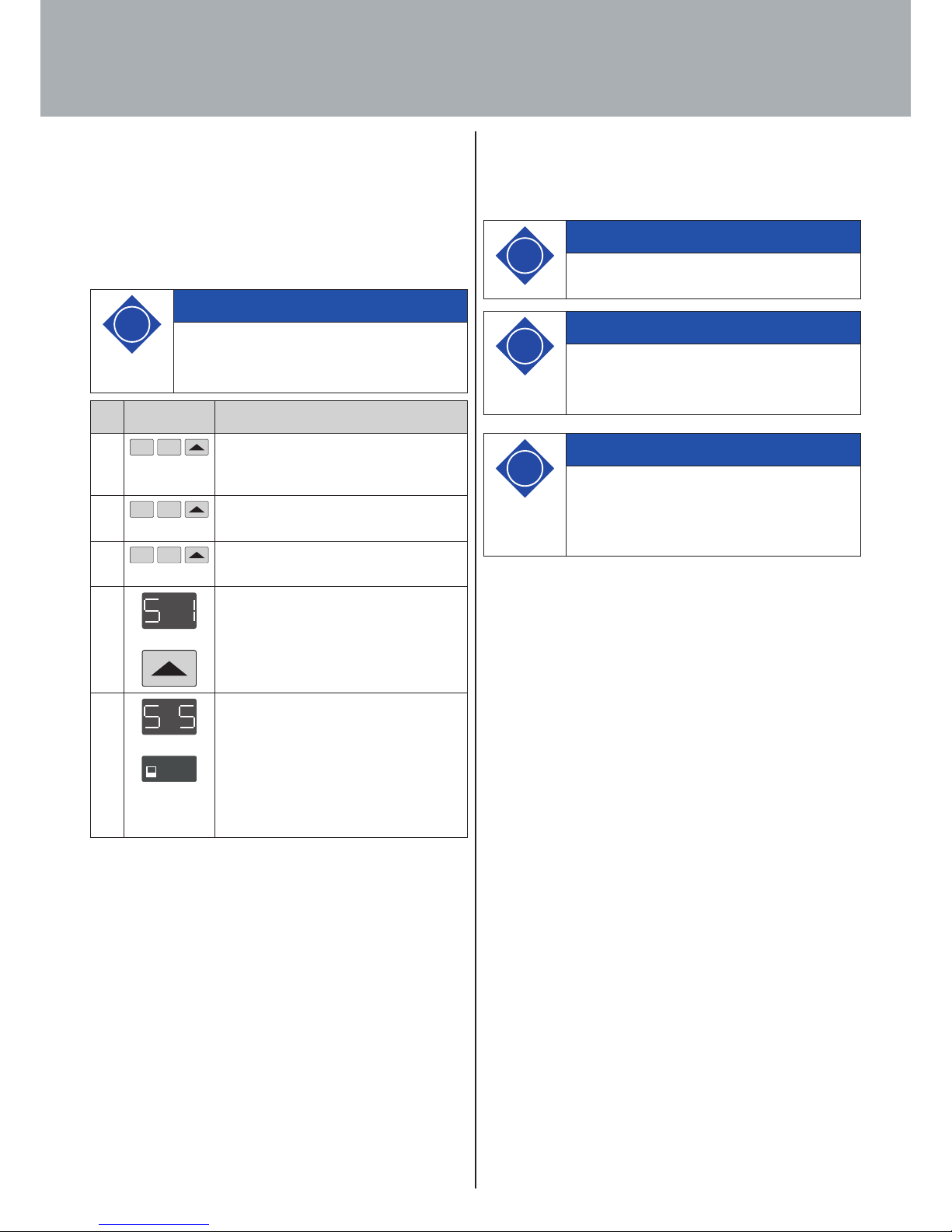
7.5.8 Changing desk height unit (cm or inch)
This function lets you change the memory handset display from
centimetre to inch and vice versa. This function does not alter
desk height.
7. Operation
i
Note
On selecting the menu, the display shows S and
a number, e.g. S 1. This number depends on the
control unit's parameters.
No. Button Function
1.
1 2
Simultaneously press memory position
button 1, memory position button 2 and
the desk top down button.
2.
1 2
Keep this button combination pressed for
approx. 3 seconds.
3.
1 2
Now release the buttons.
4.
The display shows S 1.
Keep pressing the desk top up button
until the display shows S 5.
5.
SAVESAVE
The display shows S 5.
Press the SAVE-button.
If the display was previously set to cm,
it will now be changed to inch. If the
display was previously set to inch, it will
now be changed to cm.
7.5.9 Returning control unit to factory settings
(S0 menu)
This function allows you to return the control unit to factory
settings.
i
Note
On selecting the menu, the display shows S and
a number, e.g. S 1. This number depends on the
control unit's parameters.
i
Note
If lifting columns are replaced in a system, it is
imperative to return the control unit to factory
settings first and perform a manual reset (see
Section 7.4.4).
i
Note
This procedure requires a handset with display.
Page 41
41
7. Operation
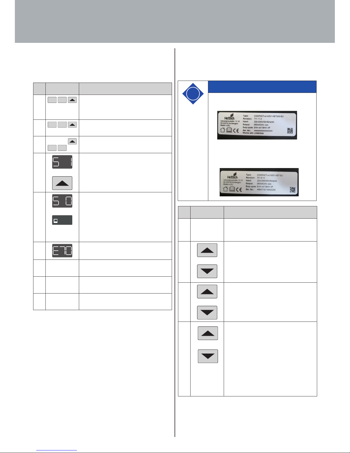
To be able to use the control unit again after changing a lifting
column‘s configuration in this way, proceed as follows:
No. Button Function
1.
1 2
Simultaneously press memory position
button 1, memory position button 2 and
the desk top down button.
2.
1 2
Keep this button combination pressed for
approx. 3 seconds.
3.
1 2
Now release the buttons.
4.
The display shows S 1.
Keep pressing the desk top up button
until the display shows S 0.
5.
SAVESAVE
The display shows S 0.
Press the SAVE-button.
The control unit is reset to factory set-
tings. The control unit is now in the same
state as during initial commissioning.
6.
Handset display shows fault code E70.
7. Unplug the control unit's power supply
and wait at least 5 seconds.
8. Plug the control unit's power supply back
in again.
9. Carry out a manual reset (see Section
7.4.4 for details).
If a handset with only one up and one down button is used,
proceed as follows:
i
Note
This is possible for control units with Revision
/1.11.3.
For control units with Revision /1.9.14 or older,
resetting to factory settings is only possible with
a handset with display.
No. Button Function
1. Disconnect the power supply of the con-
trol unit and wait at least 5 seconds.
2.
and
While the control unit is disconnected
from mains power, press the desk position
down and desk position up buttons
simultaneously. Press and hold this key
combination.
3.
and
Keep this key combination of desk top
down and desk top up pressed while
reconnecting the control unit to mains
power.
4.
and
Keep this key combination of desk top
down and desk top up pressed until the
control unit begins to click twice per se-
cond. Release the two buttons as long as
the control unit clicks twice per second.
The control unit is reset to factory set-
tings. The control unit is now in the same
state as during initial commissioning.
Page 42
42
7. Operation
7.5.10 Cascading
Cascading provides the capability of connecting several control
units for operating as many as twelve lifting columns running in
synchrony.
i
Note
Parameters must first be set to define whether a
control unit is used for cascading. Functions may
vary slightly from those of an individual control
unit.
i
Note
For further information on cascading please refer
to the manufacturer's separate operating inst-
ructions on "Cascading LegaDrive control units".
5. Unplug the control unit‘s power supply
and wait at least 5 seconds.
6. Plug the control unit‘s power supply back
in again.
7. Carry out a manual reset (see Section
7.4.4 for details).
Page 43
43
8. Troubleshooting
8.1 Safety advice
Lifting column system malfunctions must only be rectified by
specialists instructed to do so by the person responsible.
In identifying the source of malfunction attention must be paid
to the entire area surrounding the lifting column system. The ma-
nufacturer must be immediately notified of any damage occurring
during the warranty period.
Warning
Safety regulations while identifying the
source of malfunction and rectifying malfunc-
tion!
Observe the accident prevention regulations!
In the event of a mechanical malfunction, make
sure that the lifting column system is disconnec-
ted from the power supply!
The lifting column system must be disconnec-
ted from the power supply before commencing
troubleshooting!
Disconnect the power supply cable from mains
power supply and take action to prevent it from
being plugged back in unintentionally.
Page 44
44
8. Troubleshooting
8.2.1 Potential malfunctions and how to remedy them
Lifting columns not working
Lifting columns only operating in one direction
*) if the drives are only providing downward movement.
Possible cause Remedy
Power supply cable
is not plugged in.
Plug the power supply cable into the
control unit.
Lifting columns are
not plugged in.
Plug the lifting column cable into the
control unit.
Power supply cable
faulty (e.g. cable
break)
Change the power supply cable.
Poor plug contact Properly plug in the lifting column cable,
the power supply cable and the handset
cable.
Control unit faulty Contact customer service.
Handset faulty Change the handset.
Lifting column
faulty
Contact customer service.
Possible cause Remedy
Power failure
during height
adjustment or
power supply cable
unplugged
during height
adjustment.
Carry out a manual reset (see Section
7.4.4). *)
Control unit faulty Contact customer service.
Handset faulty Change the handset.
Lifting column
faulty
Contact customer service.
8.2 Malfunctions
This section provides you with detailed information on the fol-
lowing subjects:
· Potential malfunctions and how to remedy them
· Fault messages on the handset display
· Control unit click codes
Page 45
45
8. Troubleshooting
8.2.2 Faults indicated on the handset display
The display shows HOT.
The display shows four dashes.
The display shows E + a fault number.
Possible cause Remedy
The display handset was
connected to the control
unit while the control unit
was connected to mains
power voltage.
Disconnect the power cable from
the mains power voltage. Leave
the control unit voltage-free for
approx. 10 seconds. Reconnect the
power cable to the mains power.
Display not working (buttons working)
Buttons not working (display working)
Control unit or handset not working (neither display nor but-
tons)
Possible cause Remedy
Cable is faulty Change the handset
Display is faulty Change the handset
Microcontroller is
faulty
Change the handset
Handset is faulty Change the handset
Possible cause Remedy
Cable is faulty Change the handset
Handset is faulty Change the handset
Buttons were
pressed on startup
Unplug the handset and then plug it back
in again without touching the control
panel
Possible cause Remedy
Cable is not
plugged in.
Plug the cable into the socket intended
for it and marked HS
Cable is not
plugged in properly.
Plug the cable into the socket intended
for it and marked HS
Poor plug contact Unplug the cable and then plug it back in
properly
Cable faulty Change the handset
Handset is faulty Change the handset
Poor plug contact Properly plug in the lifting column cable,
the power supply cable and the handset
cable.
Remote handset
faulty
a) No battery in the remote handset or
battery empty.
(Refer to section 6.2.2.2 “Replacing the
battery”).
b) Remote handset not programmed.
(Refer to section 6.2.2.1 “Programming”).
Possible cause Remedy
An internal fault has occurred in the control unit.
Proceed as described in the following fault list.
Possible cause Remedy
The control unit is protected from
overheating. Overheating
has activated this
overheating protection.
Wait for the control unit to cool
down and the HOT message to go
out on the display. The control unit
is now ready for operation again.
Page 46
46
8. Troubleshooting
8.2.3 Control unit click codes
As soon as the control unit is supplied with power, it uses the
built in relays to generate acoustic signals informing the user
of system status as well as of the reason for the last shutdown.
The table below shows the number of clicks generated and the
information they provide.
Number of clicks Status information
2x
Normal operation:
The system is working without any
problem.
1x
Emergency operating mode:
The system is in emergency mode,
the drives cannot be used. Check
the fault code on the handset
display.
3x to 6x
Last shutdown not completed /
forced reset:
Check the fault code on the handset display.
i
Note
PowerFail Detection is identifying power failures
and saving all relevant data before the voltage
drops below a critical level.
In a few cases of exception data cannot be
saved. The next time the control unit is switched
on, the display then shows E81 and the control
unit clicks three times. A manual reset must be
performed to rectify this fault (see Section 7.4.4).
Description Remedy
00
Internal fault on
channel 1
Switch the control unit o.
Contact customer service.
01
Internal fault on
channel 2
02
Internal fault on
channel 3
12 Fault on channel 1 Unplug the control unit.
Rectify the external short circuit.
Or:
Plug in the correct lifting column
at the socket concerned.
Put the control unit back into
operation.
13 Fault on channel 2
14 Fault on channel 3
24 Motor M1 overcurrent Remove the trapped objects from
the adjustment zone.
If desk overloaded:
Remove load from desk.
Contact customer service.
25 Motor M2 overcurrent
26 Motor M3 overcurrent
48 Motor group 1
overcurrent
49 Motor group 2
overcurrent
60 Collision detection
62 Control unit over-
current
36 Plug detection on
motor socket M1
Plug in the correct lifting column
at the socket concerned.
Carry out a manual reset
(see Section 7.4.4).
37 Plug detection on
motor socket M2
38 Plug detection on
motor socket M3
61 Motor changed
55
Motor group 1
cannot be
synchronised
Remove load from desk.
Carry out a manual reset
(see Section 7.4.4).
If the fault is still shown after
resetting, contact customer
service.
56
Motor group 2
cannot be
synchronised
67 Voltage too high Unplug the power supply cable
and contact customer service.
70 Changed
drive configuration
See section 7.5.5
81 Internal fault Carry out a manual reset
(see Section 7.4.4). If the fault is
still shown after resetting, unplug
the power supply cable and plug it
back in again after a few seconds.
If this fault occurs on a regular
basis, unplug the power supply
cable and contact customer
service.
Page 47
47
9. Servicing and maintenanc
9.1 Safety advice
Warning
Risk of injury!
· Only carry out servicing work with the lifting
column system LegaDrive shut down.
· Make sure the lifting column system LegaDrive
is prevented from switching back on unintenti-
onally.
· Follow the safety advice and accident preven-
tion regulations when using oils/lubricants,
cleaning agents and replacement parts of the
respective manufacturer!
· Regularly check the electrical system in accordance with
VDE guidelines.
· Meet all national provisions/regulations.
· Clean the entire desk support at least every 2 weeks
(recommended).
The life of the lifting column system LegaDrive will depend on
proper use and adherence to regular servicing intervals.
Warning
Risk of injury!
Servicing and maintenance work must only be
carried out by instructed, skilled personnel.
i
Note
If lifting columns are replaced in a system, it is
imperative to return the lifting columns to
factory settings first (see Section 7.5.9) and per-
form a manual reset (see Section 7.4.4).
Warning
Risk of injury!
· The basic safety advice provided in the subsup-
pliers' documentations must be followed.
· The manufacturer does not allow any flame
cutting, welding, soldering and grinding work to
be performed on the lifting column system.
Danger
Danger to life!
Servicing work on the lifting column system's
electrical connections or on the electrical auxiliary
/ control connections must only be carried out by
qualified electricians.
The lifting column system must be disconnec-
ted from the power supply before commencing
troubleshooting!
Disconnect the power supply cable from mains
power supply and take action to prevent it from
being plugged back in unintentionally.
Danger
Danger to life from manipulating the protective
guards!
Manipulated protective guards will not provide any
protection in the event of a hazard. This may lead
to fatal injuries to personnel and damage to the
lifting column or other property.
· Safety devices must never be removed or ren-
dered ineffective for assembly
/ reassembly and
repair work.
Page 48
48
9. Servicing and maintenance
Warning
Risk of injury from failure to observe safety
measures!
Any failure to follow safety measures may lead
to injury to the persons present at the desk sup-
port and to serious damage. Before commencing
and while performing work involved in servicing,
maintenance and troubleshooting activities
implement the applicable safety measures and
follow them.
Warning
Risk of injury from failure to observe safety
measures!
The enclosures around the LegaDrive's compo-
nents must not be opened, removed or damaged.
Failure to observe this warning may result in
injuries!
Warning
Risk of falling/tripping hazard!
Dirt, remains of consumables and auxiliary
substances as well as any replacement parts and
tools left lying about present a risk of falling or
tripping hazard.
Persons can suer serious injuries from falling.
· Keep the workplace, in particular handles, steps
etc., free of dirt.
· Dispose of consumables and auxiliary subs-
tances in the proper manner and carefully put
away replacement parts and tools.
i
Note
Improper maintenance will result in damage to the
desk support!
Improper disassembly and assembly may result in
property damage or consequential damage to the
desk support.
Therefore, when carrying out any removal or dis-
mantling activity, always:
· mark which parts belong together
· mark and note down the place where parts are
fitted
· remove and keep assemblies separately from each
other
After carrying out maintenance work, always:
· check all screw connections to make sure they are
tight,
· close and screw down all covers.
Page 49

49
9. Servicing and maintenance
9.3 Labelling, information signs
Labelling/information signs must be
· cleaned with a cloth,
· checked for secure attachment and legibility,
· replaced if they are damaged.
9.2 Checking safety devices
Regularly check safety devices to make sure they are complete
and in proper working order.
Page 50
50
10. Taking out of service
When taking the system out of service the mains power cable
must be disconnected from the mains power supply.
Danger
Danger from electric shock!
Work on electrical equipment must only be carried
out by authorised electricians!
Page 51
51
11. Disposal
11.1 Protecting the environment
Sort materials before disposal and dispose of them in an environ-
mentally friendly manner. Electrical and electronic components
must be disposed of as hazardous waste.
Caution
Caution!
The obligations prescribed in law with regard to
avoiding waste and proper recycling/disposal
must be met when carrying out any work on the
lifting column system!
Particularly when carrying out installation, repair
and servicing work, substances hazardous to
water, such as
· lubricating greases or
· solvent based cleaning fluids must not be allo-
wed to pollute the ground or enter the sewer
system!
These substances must be kept, transported,
loaded and disposed of in suitable containers.
Information
Immediate remove empty button cells (batte-
ries) and dispose of them in an environmentally
friendly manner. They must not be discarded with
household rubbish!
i
Page 52
52
11. Disposal
11.2 Scrapping
If the lifting columns system LegaDrive is ever taken out of
service for good, the laws and regulations in force at that time of
disposal must be observed and met.
The entire energy supply system must also be dismantled and
removed at the time of final shutdown and disposal.
To avoid danger to life from electric shock:
It makes sense to check which materials can be recycled and then
also do so.
Danger
Danger from electric shock!
The work involved in dismantling and removing
the electrical equipment must only be carried out
by trained electricians!
Page 53
53
12. EC Declaration of Incorporation
- Translation -
EC- Declaration of Incorporation
of Partly Completed Machinery In accordance with Annex II B of
DIRECTIVE 2006/42/EC OF THE EUROPEAN PARLIAMENT AND OF THE COUNCIL of 17 May 2006
On behalf of the company
Paul Hettich GmbH & Co. KG
Vahrenkampstraße 12-16
32278 Kirchlengern
declares the undersigned:
For the lifting column system for an electrically height-adjustable workstation
Type
LegaDrive
the following essential requirements of the directive have been applied in the risk assessment and are complied
with, insofar as the condition of the equipment offered and delivered by Hettich permits for the assessment:
1.2.6; 1.3.1; 1.3.7; 1.3.9; 1.5.1; 1.5.2; 1.5.6; 1.5.8; 1.5.10; 1.5.11; 1.6.3
The product also complies with the following European directives*:
DIRECTIVE 2014/35/EU OF THE EUROPEAN PARLIAMENT AND OF THE COUNCIL of 26 February 2014 Making available on the market of electrical equipment designed for use within certain voltage limits
DIRECTIVE 2014/30/EU OF THE EUROPEAN PARLIAMENT AND OF THE COUNCIL of 26 February 2014 -
Electromagnetic compatibility
DIRECTIVE 2011/65/EU OF THE EUROPEAN PARLIAMENT AND OF THE COUNCIL of 8 June 2011 -
Restriction of the use of certain hazardous substances in electrical and electronic equipment
Within the scope of the conformity assessment, the necessary special technical documents have been prepared
and filed. The national authorities may, if they so request, be provided with specific documents in paper or
electric form.
Note: The incomplete machine of type „LegaDrive“ may only be commissioned when it has been established that
a machine in which „LegaDrive“ has been installed complies with the provisions of the machine directive.
This declaration of incorporation expires if significant changes are made to the entire system or parts of the
system without the written consent of the manufacturer.
* For information on the standards applied by subcontractors see their EC declara tions of conformit y and incorporation.
The above mentioned special technical documents can be requested from:
Name / address of the EC documentation authorized representative:
Eckhard Meier
Name
Managing director
Function in the company
Paul Hettich GmbH & Co. KG
Vahrenkampstraße 12-16
32278 Kirchlengern
Address
Place, date:
Kirchlengern,
Eckhard Meier
Name / signature
Page 54

Paul Hettich GmbH & Co. KG
Vahrenkampstr. 12-16
32278 Kirchlengern
 Loading...