


Operating manual
BlueMax Mini Modular Plus

Contents
1. Foreword
1. Introduction 5
2. Important advice 5
Revision service 5
Updating 5
3. Validity of this operating manual 5
Application 5
Copyright reserved 5
4. Owner's personal responsibility 5
5. Service 5
2. EC declaration and protocols
1. EC Declaration of Conformity 6
2. Important note 7
3. Verification of instruction 7
3. General safety rules
1. Information on signs, symbols and markings 8
2. General 9
3. Safety advice for the user company 10
4. Noise 10
5. Oils, greases and other chemical substances 10
6. Residual risk 10
7. Safety advice for operating personnel 11
8. Safety advice for operating the machine 11
9. Safety advice for carrying out maintenance work 11
10. Training / instruction 11
11. Personal protective equipment 12
4. Purpose / operating principle
1. General information 14
2. Intended use 14
3. Foreseeable incorrect use 14
4. Operating principle and description of the machine 15
Description of the machine 15
5. Rating plate 15
6. Limit values 15
7. Liability 15
5. Technical information
1. Safety advice 16
2. Attachment points 16
3. Technical specifications 17
4. Equipment 18
Setting 22
5. Safety guards 22
6. Noise mission 23
7. Aligning / fastening 23
General information 23
8. Connections required 23
Main power connection 23
Compressed air connection 23
9. Handling 23
Transportation via fork lift truck or pallet jack 24
10. Internal handling 24
11. Checking delivery for missing items 24
12. Dealing with shipping damage 24
13. Measures for temporary storage 24
14. Site of installation 24
15. Safety guards to be provided by the owner 25
16. Permissible ambient conditions 25
17. Removing preservatives 25
18. Electrics 25
19. Compressed air connection 25
20. Suction extractor 25
2
2
6. Start up / trial run
1. General 27
2. Safety check 27
3. Malfunctions on start up 27
4. Starting up for the first time 27
5. Machine versions supplied 28
6. Interchangeable drilling units 29
Interchangeable drilling unit, 3 spindles Selekta 29
Interchangeable drilling unit, System 32 hole line 29
Interchangeable drilling unit, System 32 hole line 90° 29
7. Other accessories 29
8. Assemblies 30
Press in frame for the interchangeable drilling unit, 6 spindles 30
Centre stop 31
Continuation stops 31
Drilling depth settings 32
Drum stop 33
Hold-down clamps 33
Converting from manual operation to foot switch 34
Connecting foot switch for a machine with horizontal
drilling unit 34
Connecting foot switch for a machine without
horizontal drilling unit 35
9. Carrying out trial run 36
10. Concluding start up 36
7. Setting up
1 . Preparing machine 38
Readiness for use 38
Connecting to extractor system 38
Connecting to compressed air supply 39
Connecting to power supply 39
Switching on 40
Operating 40
Drilling hole line, interchangeable drilling unit, 9 spindles 41
Inserting hinges 42
2. Setting up (preparing for work) 42
Tools used (drill bits) 42
Interchangeable drilling unit, 6 spindles,
interchangeable drilling unit, 3 spindles (Selekta 22/9) 43
Interchangeable drilling unit, 9 spindles 43
Interchangeable drilling unit, 90°, 9 spindles 44
Changing interchangeable drilling units 44
Cleaning 44
Fitting drilling units 45
Checking switch for proper working order 45
Setting drilling depth, vertical drilling unit 46
Drilling with horizontal drilling unit 46
Settings on the back of the machine 47
Limiting drilling stroke for drilling hole lines 48
3. Hold-down clamps and centre stop 48
Hold-down clamps 48
Centre stop 49
Setting the drum stops 49
Pendulum stops 49
8. Operation
1. Safety check 50
General information 50
Readiness for use 50
Controls 51
2. Switching on 52
Preparatory work 52
3. Operating 52
Hold-down clamps 53
Fitting Hettich hinges 53
Drilling 54
Pressing in 54
4. Malfunctions during operation 55
Troubleshooting 55
5. Checks during operation 55
Checks for proper working order 55

9. Servicing / care
14. Instructions for installing accessories
1. General information 56
Working on electrical components 56
2. Instructing maintenance personnel 56
3. Making the machine safe on shutdown 57
4. Cleaning the machine 57
Electric motors 57
5. Servicing work 57
Servicing and maintenance 57
Servicing unit 58
6. Instructions on inspections 58
General 58
10. Malfunctions / troubleshooting
1. General information 59
2. Malfunctions caused by the owner 59
3. Troubleshooting 59
General causes of malfunction 59
Malfunctions while machine is operating 59
4. Reporting malfunctions 59
11. Dismantling / disposal
1. General information 60
Before dismantling 60
2. Taking out of service 60
3. Dismantling 61
General information 61
Dismantling the machine / system 61
4. Hazardous substances / disposal 61
Protecting the environment 61
Scrapping 61
Oil and oily wastes 61
1. Press in frame 82
2. Converting from pushbutton to foot switch 82
Connecting foot switch for a machine
with horizontal drilling unit 83
3. Installing laser 84
4. Installing continuation stop 85
Precision adjustment of continuation stops 86
5. Installing support block 86
12. Replacement parts lists
1 Base frame 63
2. Work surface 63
3. Eccentric tensioner 64
4. Guide frame 64
5. Foot extension 65
6. Suction extractor 65
7. Cable drag chain 66
8. Console 66
9. Lifting cylinder 67
10. Drilling depth stop 68
11. Adjustable stop 68
12. Clamping element 69
13. Motor with support 70
14. Centre stop 70
15. Press in frame 71
16. Hold-down clamp, rear 71
17. Hold-down clamp, front 71
18. Continuation stop 72
19. Travel limiter 72
20. Drum stop 72
21. Horizontal drilling unit 73
22. Interchangeable drilling unit, 90°, 9 spindles 74
23. Interchangeable drilling unit, 9 spindles 75
24. Interchangeable drilling unit, 6 spindles 75
25. Interchangeable drilling unit, 3 spindles, Selekta (22/9) 75
26. Pneumatics diagram 76
27. Circuit diagram 77
13. Replacement part numbers
1. List of replacement part numbers with designation 78
3
3

Foreword
1. Foreword
1. Introduction 5
2. Important advice 5
Revision service 5
Updating 5
3. Validity of this operating manual 5
Application 5
Copyright reserved 5
4. Owner's personal responsibility 5
5. Service 5
WARNING
Read these operating instructions carefully in order
to obtain a thorough understanding of the machine
and how to install and maintain it. Operate the
machine in the proper manner as described in these
instructions so as to avoid injury and damage to the
system. Do not operate the machine on the basis of
suppositions. Keep these operating instructions to
hand and consult them if you are in any doubt as
to carrying out any particular procedure.
If any questions remain unanswered after reading
through the instructions, you must not put the
machine into operation. Settle any unanswered
questions first by consulting Hettich FurnTech GmbH
& Co. KG.
These operating instructions are intended to make it easier
for you to become familiarised with the machine and use its
capabilities in the proper manner. The operating instructions
contain important information on operating the machine in
a safe, proper and cost effective manner. Following them will
help to avoid hazards, repair costs and down times, enhance
reliability and prolong service life.
Existing national regulations on preventing accidents and on
protecting the environment are also applicable.
The machine will only be assembled and installed by
persons instructed to do so by Hettich FurnTech GmbH &
Co. KG. This also applies in particular to starting it up for
the first time.
The operating instructions must be available at the machine
all the time. The operating instructions must be read and
applied by any person entrusted with working with / on the
machine, e.g.:
• Operation
• including setting up, troubleshooting while working,
disposal of production waste, care, disposing of
consumables and auxiliary substances,
• Maintenance
• Servicing, inspection, repair
• Handling
given the task.
4
4

1. Introduction
The main objective of this operating manual is to protect
"man and machine" in accordance with the EC Machinery
Directives. It is intended for all persons involved in working
with and on this machine or system, in particular the
operating personnel.
•
As operating / servicing personnel, first read this operating
manual and familiarise yourself with using the machine
and operating it safely as well as with how to perform
the necessary set-up, servicing and / or repair work in the
proper way while meeting the safety requirements.
•
Your personal safety and that of your surroundings as
well as safe machine operation without risk to other
property or the environment will only be ensured if you
are familiar with and follow all of the information in this
operating manual as well as in pertinent health and safety
regulations.
•
As customer and / or owner, make sure that this operating
manual is given to your operating / servicing personnel
before putting the machine / system into service for the
first time, that it remains available directly at the machine
at all times and that all persons concerned observe the
information and warnings provided in this operating
manual, the code of practice applicable to the site of
installation as well as the regulations on occupational
health and safety etc.
In other words, this operating manual does not release the
owner from the duty to devise his or her own health and
safety rules as well as safe work procedures tailored to his or
her production requirements / needs, to any specific system
/ machine combination, to specific installation conditions,
to specific modes of connection and/or tool and component
properties etc., and to apply these, have them applied and
monitor their observance.
2. Important notes
Revision service
This operating manual is not subject to any revision service.
If changes / additions are made after the machine has been
delivered, it is the responsibility of the owner to update
this operating manual using his or her own addenda or any
addenda provided by Hettich FurnTech GmbH & Co. KG.
The right is at all times reserved to amend and improve
all technical specifications, details and illustrations in the
interest of technical progress.
Updating
The laws, provisions, regulations, directives, codes of practice
etc. specified in this operating manual as well as statements
derived from them were up to date at the time this manual
was compiled.
They must be heeded in their latest, applicable wording,
updated at the responsibility of the owner and always applied
in their more restrictive (stringent) wording.
We also point out that the content of this operating manual
is not part of any earlier agreement, assurance or legal
relationship or intended to amend such. All obligations on
the part of Hettich FurnTech GmbH & Co. KG arise from the
pertinent supply contract that also contains the complete and
solely applicable warranty arrangements or draws attention
to these. Statements made in this operating manual neither
extend nor restrict these warranty provisions.
3. Validity of this operating manual
•
This operating manual only applies to this machine.
•
Please always quote the machine no. in all queries and
orders for replacement parts.
Statements made in this operating manual in relation to
items of equipment not included with the machine are for
information only. They do not give rise to any legal claim to
the machine being equipped with these items.
Application
This operating manual has been produced in compliance
with EC directives, European (harmonised) standards etc.
References to occupational health and safety, environmental
protection and safety provisions may not yet conform
to harmonised accident prevention regulations (UVV) /
statutory accident insurance regulations (GUV) applicable
in Germany or to the DIN standards or technical regulations
stated in the appendix to the German Equipment Safety Act
(Gerätesicherheitsgesetz (GSG)).
The customer / owner is personally responsible for:
•
regarding specified laws, regulations, directives etc., as the
basis for safe handling and maintenance practice,
•
implementing and observing them in line with national /
regional / company-internal regulations,
•
providing supplementary safety or protective equipment
prescribed by the responsible local, regional or national
authorities and for fitting them before using the machine /
system for the first time.
Operating instructions:
Hettich FurnTech GmbH & Co. KG©
2016 by Hettich FurnTech GmbH & Co. KG
Copyright to the operating instructions
The copyright to these operating instructions remains with
Hettich FurnTech GmbH & Co. KG.
These operating instructions are intended for the operating
personnel. They contain regulations and drawings of a
technical nature that must not be duplicated either in whole
or in part, distributed, used without permission for advertising
purposes or communicated to others.
Reproduction either in whole or in part is not permitted.
4. Owner's personal responsibility
The customer or owner is personally responsible for ensuring
that
•
provisions on occupational health and safety, environmental
protection and disposal are observed in relation to the
machine, handling it as well as in the course of inspections,
servicing and repair measures,
•
no improper changes or modifications are made to the
machine or safety guards,
•
the machine is not used in any inappropriate, improper or
non-intended manner.
5. Service
Customer Service
Hettich FurnTech GmbH & Co. KG, Gerhard-Lüking-Strasse 10,
D-32602 Vlotho, Germany
5
5

EC declaration and protocols
2006/A1:2009;
2. EC declaration and protocols
1. EC Declaration of Conformity 6
2. Important note 7
3. Verification of instruction 7
1. EC Declaration of Conformity
6
6

2. Important note
Information for the owner
In addition to these operating instructions and the accident
prevention regulations in force in the country of use or at
the place of application, it is also necessary to follow the
recognised code of safe and proper working practice.
Without the consent of Hettich FurnTech GmbH & Co. KG, the
machine owner must not make any additions, alterations or
modifications to the machine that may affect safety.
Replacement parts used must meet the technical
requirements defined by Hettich FurnTech GmbH & Co. KG.
This is always ensured when using genuine replacement parts
from the applicable replacement parts list.
Only ever deploy trained or instructed personnel and clearly
define personnel responsibilities with regard to operating,
servicing and repair.
Use for other purposes and modifications
We expressly point out that the EC declaration shall become
null and void if modifications / changes etc. are made to the
machines listed above. The company making the modification
must amend the EC declaration and extend or make out
new documentation to reflect the latest modification.(Art. 8
paragraph 6 of the EC Machinery Directive)
3. Verification of instruction
By signing this protocol the undersigned confirms that the
following details and specifications are correct.
Confirmation
I hereby confirm that I have read and understood the
operating manual for the machine:
Designation BlueMax Mini Modular Plus
Type Automatic drilling and insertion machine
Machine no.
have read and understood.
I furthermore undertake to observe and follow the general
safety precautions, the servicing and care instructions
as well as power-up and operating instructions and the
provisions relating to malfunctions. I am aware that any
failure to observe these instructions and provisions may lead
to accidents, put persons at risk and result in damage to
property and the machine.
Name
Date
from / to
Instructor Person instructed Operation Safety rules Servicing
Type of instruction received
Signature
of the per-
son having
received
instruction
7
7
General safety rules
3. General safety rules
1. Basics 8
Information for operating personnel 8
2. General 9
3. Safety advice for the user company 10
4. Noise 10
5. Oils, greases and other chemical substances 10
6. Residual risk 10
7. Safety advice for operating personnel 11
8. Safety advice for operating the machine 11
9. Safety advice for carrying out maintenance work 11
10. Training / instruction 11
11. Personal protective equipment 12
1. Information on signs, symbols and markings
The safety advice in these operating instructions is structured
as follows:
DANGER
This danger note draws attention to an immediately
dangerous situation that will lead to death or serious
injuries if the safety measures are not followed.
WARNING
This danger note draws attention to a potentially
dangerous situation that may lead to death or serious
injuries if the safety measures are not followed.
CAUTION
This danger note draws attention to a potentially
dangerous situation that may lead to minor or slight
injuries if the safety measures are not followed
NOTE
This note draws attention to potential damage to
property or to a process of particular interest /
importance that may occur if the safety measures are not
followed.
In the operating instructions, hazard points are identified as
follows:
DANGER
Danger from electric shock!
Working on live components in the improper manner
presents a danger to life!
Work on electrical equipment must only be carried out
by authorised electricians!
WARNING
Hearing damage warning!
Some areas of the facility can reach noise levels of
over 80 dB (A).
Wear ear protectors when working in noisy areas!
WARNING
Danger from wood dust!
Wood dust can affect the respiratory tract.
For this reason, wear a dust protection mask.
8
WARNING
Fire risk!
Grinding and welding work must never be performed
on this machine.
Follow welding regulations and accident prevention
regulations.
WARNING
Explosion protection
Machine is not explosion-protected. Do not install
near paint shops.
WARNING
Warning - Hand injuries!
Hands could be crushed, drawn in or otherwise injured.
Never reach into the system's moving parts!
Wear hand protection!
WARNING
Warning - Hot surfaces / objects!
There is a risk of injury from touching hot surfaces
(e.g. electric motors).
Do not touch!
Work requiring specialised knowledge (e.g. electrical,
pneumatic system) must only be carried out by persons
specifically trained and suitable to do so.
Before attempting any work on the machine, turn the main
switch to the "0" position“ (OFF), make the machine safe and
disconnect from the compressed air supply.
Switch off energy sources before carrying out repair, servicing,
installation or cleaning work.
Energy sources:
• Electrical energy
• Pneumatic energy
CAUTION
Danger from residual energy!
Stored energy will not be dissipated even after switching
the system off at the main switch.
Dissipate residual or stored energy!
Switch off / dissipate energy sources:
For safety regulations applicable to third-party devices, refer
to the documentation from the third-party manufacturers
(operating instructions for bought in units).
Electrical energy via the motor switch / machine's main
switch. Additionally attach a notice when servicing or other work
is being carried out on the machine.
2. General
The machine described in these operating instructions is built
to the state of the art and is safe to operate. It complies with
DIN EN 12100.
Hazard zones are made safe in compliance with the
regulations. However, the machine may present hazards if
it is used by untrained personnel improperly or not for the
intended purpose.
This may then result in risks to life and limb, jeopardise the
machine and prevent it from working efficiently.
Any person given the task of installing, starting, operating,
servicing or repairing the machine at the user's premises must
have read and understood these instructions, in particular the
section on "Safety advice".
In his or her own interest, the safety officer at the user
company should obtain written conformation from operating
personnel that they have received instruction and training
and are familiar with all safety advice before they use the
machine for the first time.
The safety guards must never be removed or taken out of
operation.
If safety guards need removing for maintenance and repair
work, they must be refitted as soon as such work has been
completed.
The machine must only be used if it is in proper working order
and operated by trained, authorised personnel.
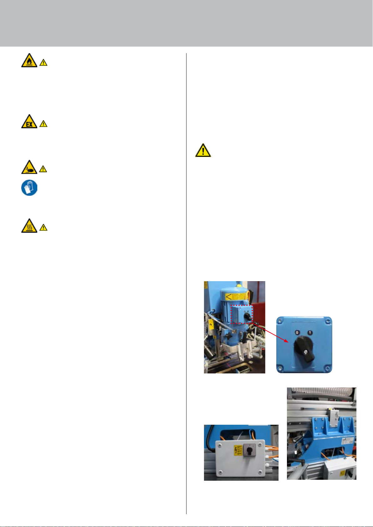
Fig. 3: Motor switch
Fig. 4: Main switch (viewed by the operator, on the right
hand side of the machine frame)
9
General safety rules
CAUTION
Warning - Hand injuries!
The main switch only shuts down the drive system, not
the pneumatic system!
The machine has no emergency STOP button or
emergency stop facility. This means it is necessary to
take particular care when handling and working on
this machine.
Pneumatic energy through the supply connection on the
machine frame. Make sure that all machine components are
depressurised and any stored energy is dissipated. As part of
the installation process, the owner will provide a mechanical
main cock at which the machine can be disconnected from
the compressed air supply.
WARNING
Never
• reach into the machine when it is operating
• remove covers and take safety guards out of operation
• hinder unobstructed access to the controls
• continue operating the machine if changes occur that
adversely affect safety
• manipulate or circumvent safety guards
4. Noise
The weighted equivalent continuous sound level is > 80 dB (A).
WARNING
Hearing damage warning!
Local conditions may produce elevated sound pressure and
cause noise induced hearing loss!
Operating personnel must be provided with appropriate
protective equipment or be protected by other measures!
Wear ear protectors when working with the machine!
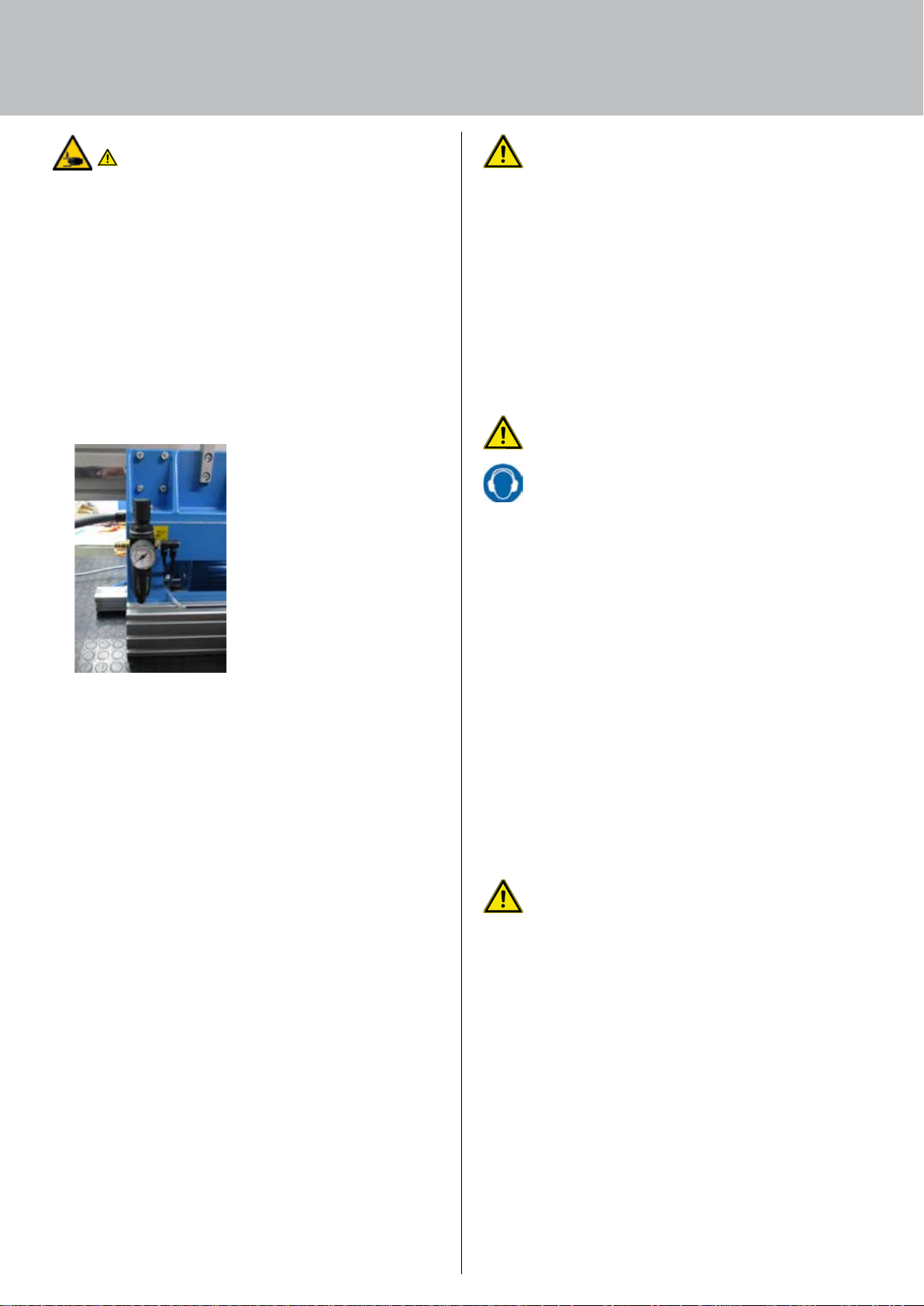
Fig. 4: Pneumatic system servicing unit (viewed by the
operator, on the left hand rear side of the machine frame)
3. Safety advice for the user company
All persons entrusted with operating the machine (including
line managers) must familiarise themselves with the section
on "Safety advice". The safety advice must be followed.
The machine must only be used if it is in proper working
order. The user company will issue clear responsibilities, e.g.
for servicing, cleaning or repair, and ensure that the persons
carrying out this type of work have received the training
necessary for it.
The safety regulations applicable in the owner's country must
also be observed. Refrain from any work that adversely affects
operating safety.
The operating personnel will check the machine for changes
or malfunctions, report such to the safety officer responsible
and, if necessary, take the machine out of operation.
Only appropriate tools may be used for the work that needs
to be done; remove tools after completing work. The place at
which staff work must be selected in such a way as to ensure
that work operations can be viewed at all times, the machine
can always be stopped immediately and safety is never at risk.
5. Oils, greases and other chemical substances
When handling oils, greases and other chemical substances,
you must observe and follow the applicable regulations and
safety data sheets of the manufacturers of these substances
with regard to storing, handling, using and disposing of them.
When working with caustic substances, you must wear
protective equipment of a suitable material (safety goggles,
rubber gloves, rubber boots, protective clothing).
In the event of contact with the eyes or skin, immediately
rinse the area affected with copious quantities of water.
Appropriate facilities (eye wash bottle, wash basin, shower)
must be provided near the work area.
6. Residual risk
CAUTION
Residual hazards!
Handling the machine involves residual hazards that could
not be eliminated by design measures.
Pay attention to the residual risks in the Technical Documentation!
The machine reflects the state of the art and is built in
accordance with recognised safety regulations. All the same,
the user or third parties may still be exposed to hazards.
The machine must be used
• for the intended purpose
• in an absolutely safe state.
10
10

WARNING
Risk of injury!
Never remove safety devices or render them ineffective by
making changes to the machine!
Malfunctions presenting a safety risk must be rectified
without delay!
Before attempting servicing and cleaning work, switch off
the entire machine and disconnect from the compressed
air supply!
7. Safety advice for operating personnel
• Work on the machine must only be carried out by
instructed, skilled personnel
• Only skilled personnel who have received training or
instruction must be deployed
• The generally recognised code of occupational health and
safety as well as accident prevention regulations must be
observed
• Please keep first aid equipment (first aid kit) in easy reach
• · The owner must stipulate that operating personnel are
to wear personal protective equipment (safety shoes and
sturdy work clothing).
Work which may be done by the operating personnel
Work which may be done by the operating personnel
• Activate, deactivate the machine
• Change drill bits
• Set the machine to component dimension
• Feed in individual parts (flat panels made of engineered
wood, hinges and connecting fittings)
• Start the drilling and inserting process
• Remove finished components
• Clean the machine
Requirements on operators
The operator must organise the work environment so as to
permit optimum, continuous production.
The operator must receive instruction before commencing
work for the first time and annually thereafter.
Prior to commencing work, all persons working on or at the
system shall undertake to
• follow the basic regulations on health and safety at work
and on accident prevention
• wear personal / workplace related protective clothing and
equipment for the purpose of ensuring work safety and use
such while working if they are necessary for safety reasons
Work must only performed for which authorisation has been
given. For example
• work on pneumatic equipment must only be carried out
by a specialist specifically trained to do so or by instructed
persons under the direction and supervision of such a
specialist in accordance with the applicable technical
regulations
8. Safety advice for operating the machine
• The machine must only be put into operation in a fully
installed and operational state
• The machine must only be operated if all protective guards
and safety related equipment, e.g. protective claddings or
enclosures, are in working order and undamaged
• On putting the system into operation, the operator must
make sure that all safety equipment and protective guards
as well as the controls are in correct working order and free
of damage
• The workplace environment must be kept clean and tidy at
all times. This must be ensured by internal checks.
• Immediately report any irregularities or malfunctions to the
department / person responsible. If necessary, the machine
must be shut down immediately and made safe
9. Safety advice for carrying out maintenance work
• Maintenance work must only be performed by
the manufacturer's skilled personnel or under the
manufacturer's supervision
• If the machine is completely shut down for servicing and
repair work, it must be prevented from switching back on
unexpectedly
• If necessary, please cordon off the maintenance zone,
providing a wide safety margin!
• Attach a warning sign
•
For maintenance measures, use tools that are appropriate for
the work involved
• Servicing and repair work must only be carried out by the
owner's qualified personnel
• If safety devices need removing for servicing and repair
work, they must be refitted and checked as soon as the
work has been completed
• Always tighten screw connections that have been loosened
during servicing and repair work
• At the start of work, connections and screw connectors must
be cleaned of oil, operating consumables and dirt
•
Make sure operating consumables and auxiliary substances
as well as replaced parts are disposed of safely and in an
environment friendly manner.
10. Training / instruction
• As owner, you are obliged to inform and instruct the
operating personnel in respect of applicable legal and
accident prevention regulations as well as the safety guards
fitted. In this context, bear in mind the varying specialised
qualifications of your staff
• The operating personnel must understand the instruction
they are given, follow it as well as sign the documentation
• This is the only way you can be sure that operating
personnel work in awareness of safety and of the hazards
that are involved. As owner, you should therefore obtain
written confirmation from all members of staff that they
have received training/instruction
• Applying these safely measures will minimise potential
hazards to such an extent that the machine can be operated
safety
11
11

General safety rules
NOTE
All of the safety guards in place must be checked at
least once before the start of each shift to make
sure that they are in place and undamaged (visual
inspection).
11. Personal protective equipment
The owner must provide the following personal protective
equipment:
• Safety shoes
• Ear protection
• Safety goggles
• Dust protection mask
• Safety gloves (as necessary)
12
12

13
13
Purpose / operating principle
4. Purpose / operating principle
1. General information 14
2. Intended use 14
3. Foreseeable incorrect use 14
4. Operating principle and description of the machine 15
Description of the machine 15
5. Rating plate 15
6. Limit values 15
7. Liability 15
1. General information
This operating manual must be kept at the machine at all
times and be constantly available there. To ensure safe
operation and proper machine handling, it is important for
you to have read and understood the operating manual
and, in particular, the safety rules. The safety provisions and
operating instructions described in this operating manual
must be followed exactly.
Regularly check this machine's safety guards and work
sequences.
Danger!
Any person given the task of installing, servicing,
starting, operating or repairing the machine must have
read and, in particular, understood these instructions.
2. Intended use
WARNING
The machine must only be used for its intended
purpose and be in a perfectly safe condition!
Operating safety is only guaranteed if the machine is
used for its intended purpose!
The BlueMax Mini Modular Plus is a semi automatic drilling
and insertion machine for panel type workpieces and the
furniture fittings intended for them. This machine must only be
used for working on flat panels made of wood-based materials,
such as chipboard, blockboard panels, MDF, solid wood or
similar materials.
Any other use beyond this is deemed to be improper and nonintended use.
Intended use also includes following the operating, servicing
and maintenance conditions prescribed by the manufacturer.
Unauthorised changes to the machine will result in the loss of
product liability and liability on the part of the manufacturer
for resultant damage.
Any other use beyond this is deemed to be non-intended
use. The manufacturer shall not be liable for any damage
this causes, with the risk involved being borne solely by the
user.
14
14
3. Foreseeable incorrect use
WARNING
Hazards may occur if the system is used incorrectly!
The following situations in particular are deemed to be
foreseeable hazardous situations:
If the machine is used for any non-intended purpose,
treated improperly or operated by untrained or
unauthorised persons, it may present a risk of injury to
personnel and a risk of damage to the machine itself.
For this reason, only trained, instructed and authorised
persons must be allowed to operate this machine.
•
Improperly assembling, starting, operating and servicing
this machine
• Operating the machine with faulty safety guards
• Operating the machine with improperly fitted safety
guards
• Operating the machine with non-functioning safety
Seite 9
Hersteller
Anschrift
Typenbezeichnung, Maschinennummern
Baujahr
guards and protective equipment
• Failing to observe the information and instructions given
in the operating manual in relation to handling, storing,
assembling, starting, operating, servicing and setting up
this machine
• Unauthorised structural changes
• Unauthorised changes to this machine's drive system
(power output, speed)
• Inadequate monitoring of machine parts subject to
particular wear
• Improperly performed repairs
• Disasters caused by the impact of foreign objects or Acts
of God
The situations above describe some of the residual hazards
which, despite being impermissible, may occur and harm the
health of staff.
The owner must observe the safety requirements defined
in the German Ordinance on Industrial Safety and Health
(Betriebssicherheitsverordnung).
4. Operating principle and description of the machine
Description of the machine
The BlueMax Mini Modular Plus is a semi automatic drilling
and insertion machine for panel type workpieces. This
machine must only be used for working on flat panels made
of wood-based materials, such as chipboard, blockboard
panels, MDF, solid wood or similar materials.
All parts being worked on are fed into the machine by hand.
Flat panels made of wood-based materials, such as chipboard,
blockboard panels, MDF and solid wood are laid on the work
table and fixed into place with the clamping equipment. The
drilling process is initiated by pressing the start button / foot
switch (optional). The start button / foot switch (optional)
must remain pressed until the drilling process has been
completed. Using the integrated insertion facility (optional),
the furniture fittings are pressed into place by means of a
manually operated press in frame (optional). This concludes
the machining process.
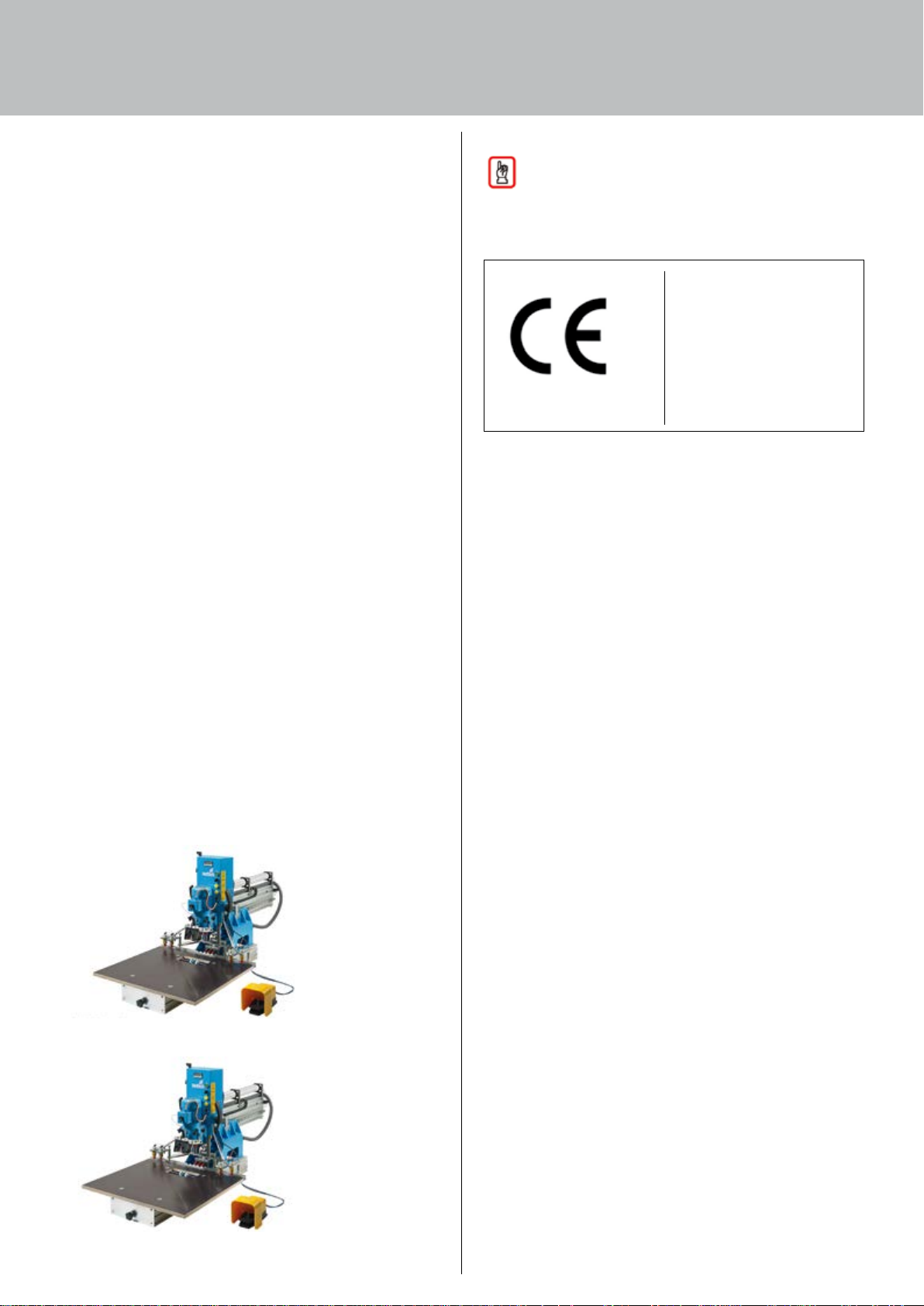
Fig. 1: BlueMax Mini Modular Plus
5. Rating plate
Note!
The rating place is located on the machine.
The rating plate shows the following information:
Manufacturer
Address
Type designation,
machine numbers
Year of manufacture
Technical specifications
(e.g. nominal pressure)
State all of the above details when requesting technical
information and ordering replacement parts.
6. Limit values
The following limit values apply to items of equipment
and accessories, such as drive motors, electric / electronic
operating equipment etc.:
• ambient temperature: max. 35°C
• rel. humidity: approx. 65%
Space required for the machine
The space required for the BlueMax Mini Modular Plus is largely
determined by the dimensions of the machine base frame.
Machine life
The machine's life will depend on whether or not it is used
for its intended purpose, on adherence to regular servicing
intervals and on the regular replacement of expendable parts.
7. Liability
Defects must only be rectified by competent personnel.
Our liability is restricted to damage caused while using
the system in the intended manner. We shall not be liable
for safety defects not yet identifiable on the basis of the
current state of the art.
Failure to observe
• safety advice for operating personnel
• advice on particular hazards
• the ban on unauthorised modifications and changes
• the use of replacement and expendable parts or auxiliary
materials other than those approved by the manufacturer
will rule out any liability on our part for the consequences
Fig. 2: BlueMax Mini Modular Plus with accessories
15
15

Technical information
5. Technical information
1. Safety advice 16
2. Attachment points 16
3. Technical specifications 17
4. Equipment 18
Setting 22
5. Safety guards 22
6. Noise emission 23
7. Aligning / fastening 23
General information 23
8. Connections required 23
Main power connection 23
Compressed air connection 23
9. Handling 23
Transportation via fork lift truck or pallet jack 24
10. Internal handling 24
11. Checking delivery for missing items 24
12. Dealing with shipping damage 24
13. Measures for temporary storage 24
14. Site of installation 24
15. Safety guards to be provided by the owner 25
16. Permissible ambient conditions 25
17. Removing preservatives 25
18. Electrics 25
19. Compressed air connection 25
20. Suction extractor 25
1. Safety advice
Observe the regulations, warnings and provisions on health,
safety and environmental protection for all of the work
described in this section.
2. Attachment points
Only use suitable and approved lifting gear (crane) for
unloading the machine, assemblies and components as well
as for lifting heavy loads; only use appropriate means of
transport for handling the machine internally.
Any unloading or internal handling must not be done by hand
if such involves weights in excess of 25 kg.
When using industrial trucks to unload the machine and move
it internally, always take into account the machine's total
permissible weight (see Technical specifications).
Danger!
Never stand or work under loads suspended on lifting
gear. This presents the risk of fatal injury!
Observe the following when using lifting gear:
•
Only attach lifting gear at the points marked (lifting
eyebolts etc.) on the machine / assemblies / components
•
Only use appropriate and tested load suspension devices
(lifting belts, ropes, chains, shackles etc.) with a sufficient
load carrying capacity
•
Only assign experienced, skilled personnel the task of
attaching the machine / assemblies / components
•
Always ensure level standing for machine / assemblies, lift
vertically, never drag at an angle
Protect projecting machine parts and equipment from damage
when using lifting gear and moving the machine internally.
Set down loads gently with the usual care and take
immediate action to prevent them from falling over / tipping,
rolling away, suffering damage from external force, e.g.
colliding with industrial trucks and objects falling from above.
16
16
3. Technical specifications
Designation: Automatic drilling and insertion machines for panel type workpieces
BlueMax Mini Modular Plus
H x W x D (mm) 862 x 800 x 1856
Weight approx. 145 kg
Power output data
Cycle time manual
Electrics
Operating voltage 400 V
Motor power 1.1 kW
HB unit power 0.55 kW
Rated current 2.65 A
Mains power fuse protection 6 A
Pneumatic system
Air pressure min. 6 bar, max. 7 bar
Noise Max. noise level: > 80 dB (A)
Temperature < 35°C
Working dimensions, vertical drilling unit
Max. workpiece thickness: 38 mm
Max. drill bit diameter: 35 mm
Max. drilling size: 30 mm
Max. pull out distance of drilling unit: 600 mm
Working dimensions, horizontal drilling unit
Max. workpiece thickness: 38 mm
Max. drill bit diameter: 8 mm
Max. drilling height: 5 – 20 mm
Max. drilling depth: 40 mm
Space required for machine
17
17
Technical information
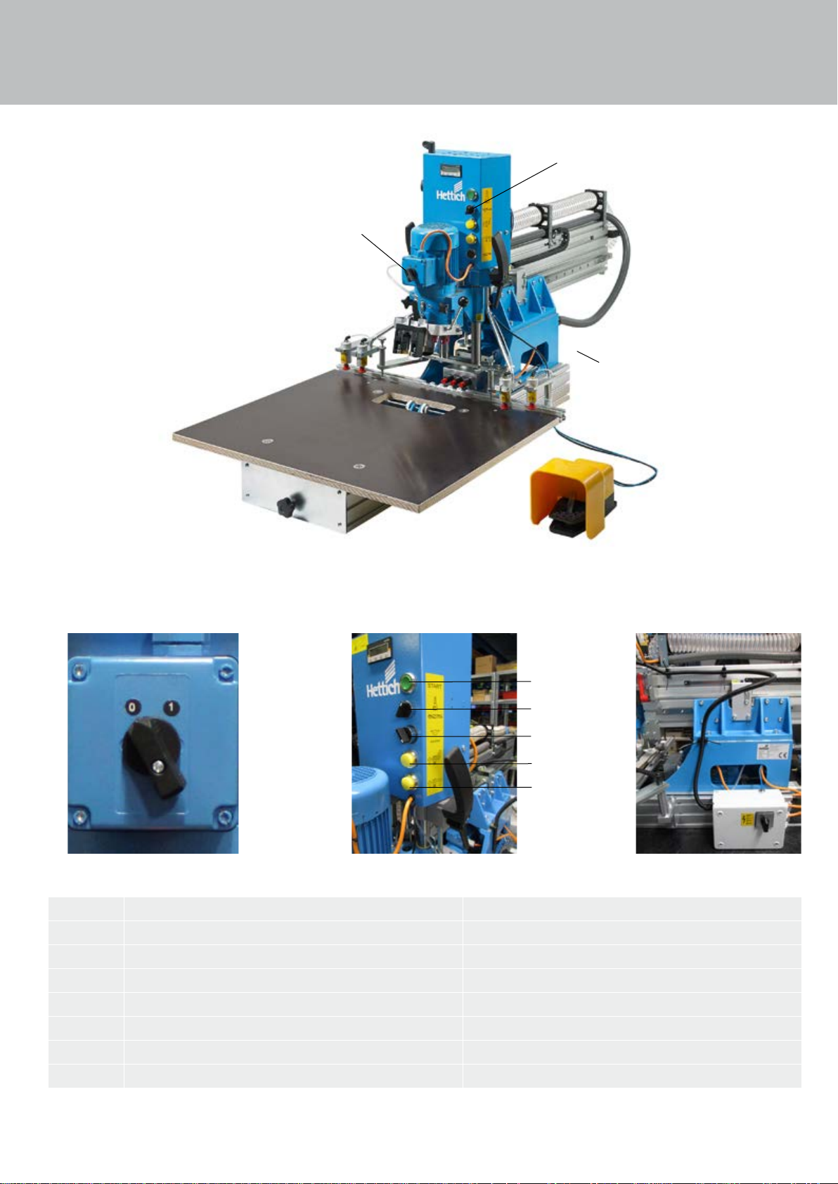
4. Equipment
Switches and other controls for operating and
monitoring the machine are described below.
2 to 6
1
7
1 7
2
to 6
2
3
4
5
6
Fig. 5: Controls on the automatic drilling and insertion machines
Item Designation Explanation
1
2
3
4
5
6
7
Motor switch Power supply ON / OFF
Pushbutton For activating work process
Change-over switch Drilling vertically / horizontally
Pushbutton For automatically unclamping the hold-down clamps
Pushbutton For manually releasing the front hold-down clamps
Pushbutton For manually releasing the rear hold-down clamps
Main switch Machine power supply ON / OFF
1818
18
1
NOTE
The pushbutton is not operational when using
the foot switch.
Fig. 6: Foot switch (optional)
Item Designation Explanation
2
1
Foot switch (optional) For activating work process
Fig. 7: Compressed air connection
Item Designation Explanation
1
2
Pressure regulator For setting operating pressure (6-7 bar)
Plug in coupler Compressed air connection
1919
19
Technical information
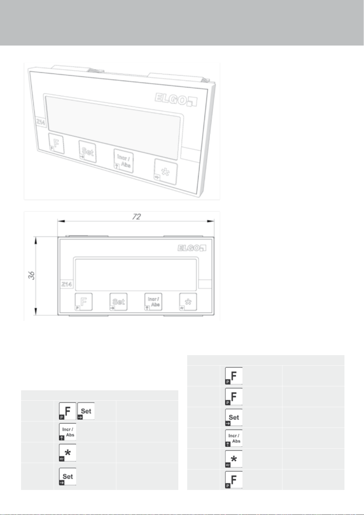
Digital display
Fig. 8: Position display panel
Operating mode:
Reference
value
Chain
dimension
Offset
dimension
Inch display
2020
20
Press simultaneously
Switch over incremental
- absolute
This button activates the
selectable offset dimensions
Switch over to inch
mode, fraction notation
(1/64, 1/32, 1/16), decimal 0.001
Parameter level:
Activate
parameter
level
Select
parameter
Select
decades
Increase
decade
Change
sign
Leave parameter level
Press for approx. 3
seconds
Press button once
Press button once
Press button once
Press button once
Press for approx. 3
seconds

Parameter Specification Default
System configuration:
P01: A
P02: A
P03: A Decimal point (0…4) 2
P04: A
P05: ABC
P07: A
A = 0: positive counting direction
A = 1: negative counting direction
Display mode:
A = 0: mm display symbol " mm "
A = 1: inch display symbol " Inch "
A = 2: mm display symbol " m "
A = 3: mm display symbol " ° "
A = 4: mm display no symbol
Standby:
0: Sleep mode deactivated (not recommended)
Auto power ON when sensor moving or
button press (button F)
Button lock:
A: " SET " (0 = not active) -
(1 = active)
B: " Incr/Abs " (0 = not active) -
(1 = active)
C: " * " (0 = not active) -
(1 = active)
Basic resolution:
A = 0: resolution 0.01 mm
A = 1: resolution 0.1 mm
0
0
01
000
0
P08: Multiplication factor (0.0001…9.9999) 1.0000
P09: Reference value (-999999.9… + 999999.9) 0.0
P10: Offset dimension 1 (-999999.9… + 999999.9) 0.0
P11: Offset dimension 2 (-999999.9… + 999999.9) 0.0
P12: Offset dimension 3 (-999999.9… + 999999.9) 0.0
Configuration of offset dimensions (0…3)
A = 0: offset dimensions cannot be
selected
P13: A
P9: Software version X.XX
A = 1: offset dimension 1 can be selected
A = 2: offset dimensions 1 and 2 can be
selected
A = 3: offset dimensions 1 and 2 and 3
can be selected
Calibration:
The sensor must be on the magnetic strip!
> Switch off device
3
–>
Switch device back on again by simultaneously pressing
button
–> This triggers the sensor calibration and displays "Cal 0".
Slowly move sensor in one direction on the magnetic strip.
On completion of calibration (display "Cal 0" … "Cal 4") the
display returns to the normal status
2121
21
Technical information
Setting
WARNING
Setup work may only be performed by qualified staff who,
on the basis of their specialised training, experience and
instruction, possess sufficient knowledge of
• safety rules
• accident prevention regulations
• guidelines and generally accepted codes of practice
These qualified staff must be authorised to perform
setting up work by the person responsible for the
machine's safety.
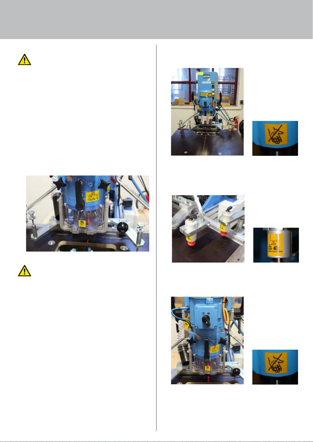
5. Safety guards
Separating protective guards complying with EN 953 are
installed on the machine to protect staff from mechanical
hazards.
Warnings / pictograms are also provided on the machine.
Labelling
Area: entire machine
Warning of the risk of hands being crushed
Fig. 10: Labelling – entire machine
Area: hold-down clamps
Warning of the risk of hands being crushed
Fig. 9: Transparent cover
WARNING
The guards must not be modified, tampered with or taken
out of operation.
The machine has no emergency STOP button or emergency
stop facility. This means it is necessary to take particular
care when handling and working with this machine.
Fig. 11: Labelling – hold-down clamps
Area: protective cover on tools
Warning of the risk of hands being crushed
Fig. 12: Labelling – drilling and insertion unit
22
22
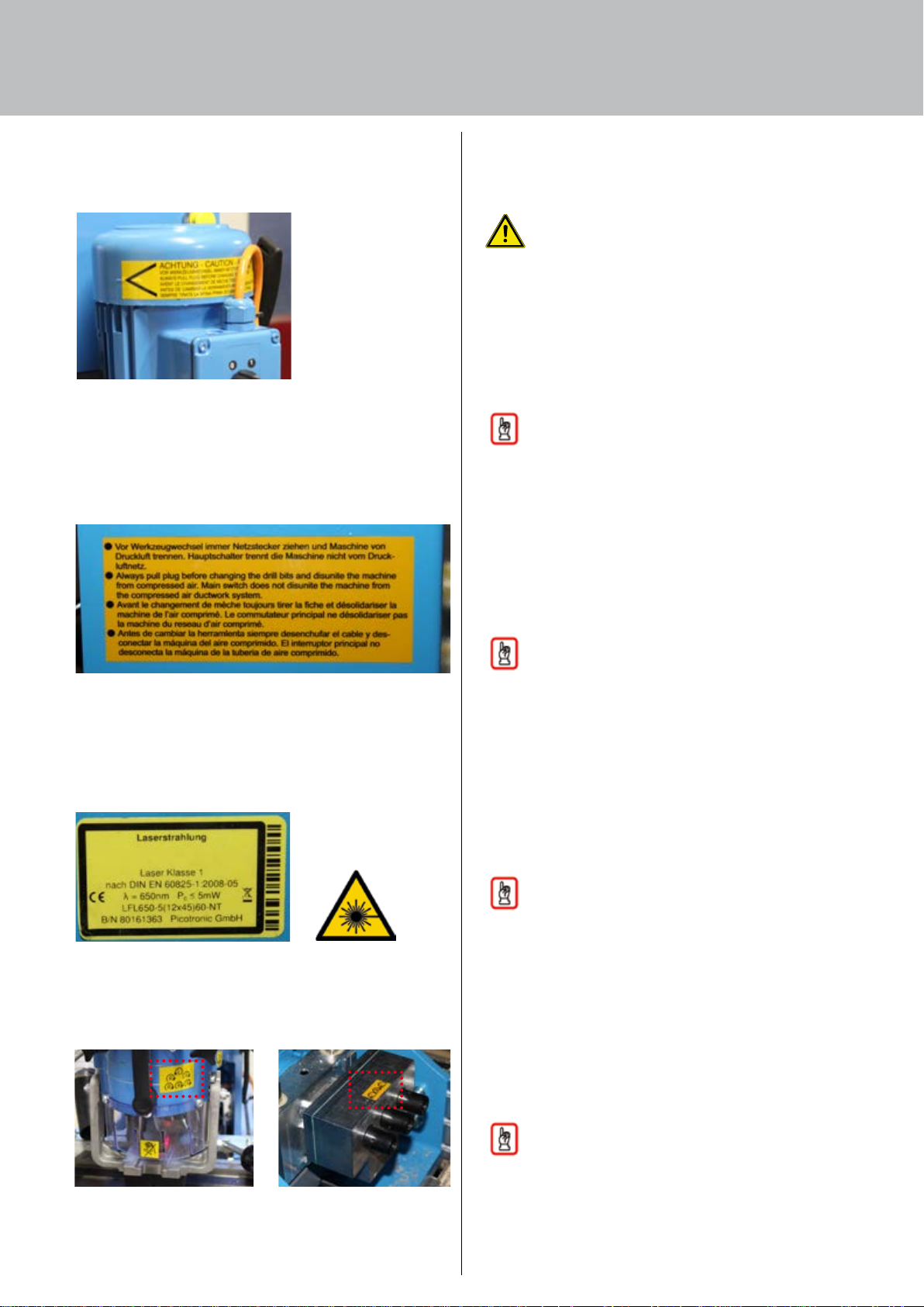
Area: motor / drive
Reminder to unplug the mains power plug before
changing tools
Fig. 13: Labelling – Motor / drive
6. Noise emission
This machine operates at a noise level above 80 dB(A). We
recommend wearing ear protectors at all times to prevent
damage to hearing.
WARNING
Wear ear protection.
7. Aligning / fastening
General information
The machine should be installed on a level, load-bearing
stand with firmly standing feet.
Any machine must be installed in a way that prevents it from
moving about and tipping over.
Area: entire machine
Reminder to unplug the mains power plug and disconnect
compressed air before changing tools. Main switch does not
disconnect the machine from the compressed air system.
Fig. 14: Labelling – entire machine
Area: protective cover on tools
Labelling on laser beam
NOTE
Securely installed machines prevent accidents.
8. Connections required
Main power connection
Connection to the electrical power supply is made by
connecting a 16 A plug
2 to a prepared socket 1 with
appropriate fuse protection.
Care must be taken not to damage electrical supply leads.
These must be changed whenever necessary.
NOTE
Before plugging in, instruct a qualified electrician to
check the socket.
Compressed air connection
The entire machine is connected to a central in-house
compressed air supply system.
The supply line is fitted with a plug in coupler
The operating pressure must be set to 6 - 7 bar at the
pressure regulator
1.
2.
This must be checked at the pressure gauge.
Fig. 15: Labelling – laser beam
Area: drill bits
Labelling on turning direction of drill bits
Fig. 16: Labelling – turning direction of drill bits
NOTE
Only feed in dry compressed air as the pneumatic
system is largely operated on unoiled air.
9. Handling
The machine must only be transported and installed by
companies / persons instructed / authorised to do so by the
manufacturer or under the manufacturer's supervision.
After moving the machine, every part of it must be checked
for shipping damage as possible harm may impair system
operation and safety.
NOTE
To prepare transportation, please bear in mind the weight
of the machine!
The machine weighs approx. 145 kg.
23
Technical information
Transportation via fork lift truck or pallet jack:
If fork lift trucks or hand pallet jacks are used for loading or
unloading, they must be in proper working order and suitable
for carrying the weights that are involved.
Attention must always be paid to the
centre of gravity of the item being moved!
During transportation, the machines must be properly
secured; the load must be evenly distributed. Avoid jerky
movements.
Set the machine down without bumps or jolts as well as in an
upright standing position. Take immediate action to prevent these
from being damaged by transportation vehicles and from tipping
over.
On unloading, handling and keeping the machine in
temporary storage, treat it with the greatest possible care and
protect it from the weather, impact of external force and from
falling objects.
WARNING
Warning of suspended loads!
To relocate the machine, it must be lifted and transported.
The machine can topple over and fall as a result of
improper lifting and transportation.
Never stand under suspended loads!
WARNING
Warning of suspended loads!
While transporting the machine, no persons must be
present on the machine or hang from it.
10.
Internal handling:
To move the machine internally, only use trolleys of sufficient
stability and load bearing capacity. When handling, always be
sure to avoid knocks and vibration. Provide protruding objects
(motors, drag chains, wiring harnesses, hoses, cylinders) with
effective protection from damage.
13.
Measures for temporary storage
The machine is designed for immediate installation and start
up. The following measures must be taken if this does not
take place within a reasonable period of about 3 months
after receiving the machine:
•
Coat bare metal parts with corrosion inhibiting oil.
•
Cover the control system, electrical devices / operating
equipment, drive motors to protect them from moisture and
dust.
•
Taking particular care, cover / use adhesive tape to seal off
cable inlets into terminal boxes and plugs.
•
Protect wiring harnesses from vermin. Mice and rats are
particularly partial to highly flexible cables.
• Store the machine in a dry, frost free room.
• Also observe the storage instructions.
Apply appropriate measures to protect the stored machine
from tipping over, falling objects, impact from external
force (e.g. industrial vehicles bumping into it), knocks and
vibrations.
14.
Site of installation
An even standing surface with a sufficient load bearing
capacity is essential for setting up the machine in a proper
and safe manner. Any unevenness in the standing surface
must be evened out by metal shims to ensure that the
machine is not standing in a distorted manner.
The BlueMax Mini Modular Plus comes in secure shipment
packaging for safe transportation. A number of components
must be installed to make the machine ready for operation.
After installing the machine, it must be cleaned.
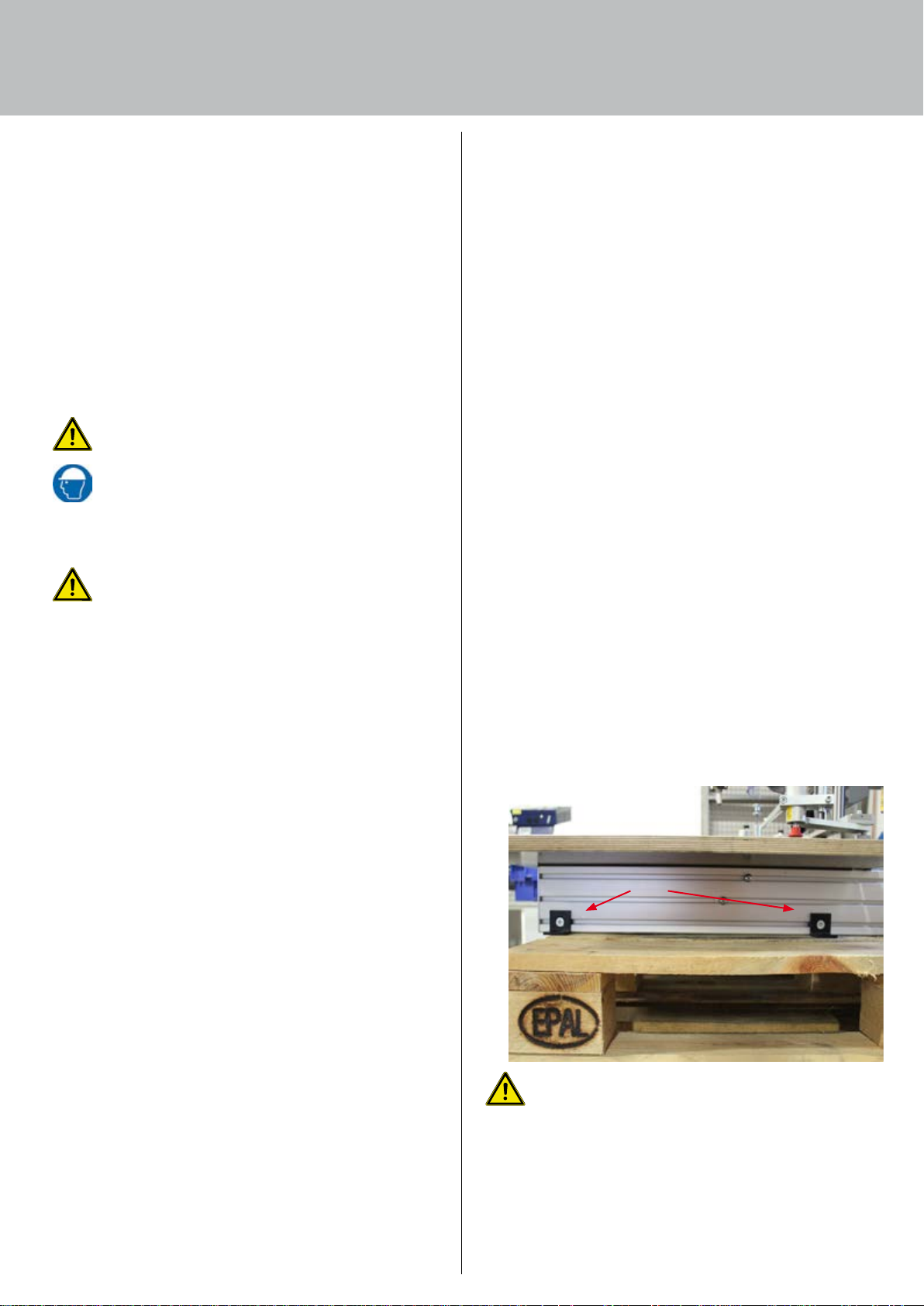
Using the 4 black brackets
conjunction with sliding block on the foot profile), secure the
machine on a bench / base frame to be provided at the site of
installation so as to prevent the machine from falling.
1 supplied with the machine (in
11. Checking delivery for missing items
Refer to the order confirmation or the list in this operating
manual as well as the delivery note to ascertain what should
be included. On receipt, immediately check to make sure a
delivery is complete. Notify the shipping company making
the delivery of any missing parts (notice of loss) and also
immediately inform Hettich FurnTech GmbH & Co. KG.
12.
Dealing with shipping damage
Immediately after arrival and unloading, thoroughly check the
machine for any shipping damage, i.e for externally visible
damage (fractures, dents, kinks, cracks etc.).
Any suspected shipping damage must immediately be:
• reported in writing to the shipping company making the
delivery (forwarder) and/or
• reported in writing to your own insurance company as well
if the transportation risk was insured by the owner
24
1
CAUTION
Risk of crushing!
Allow a space of at least 500 mm between moving
machine parts and pillars, parts of the building, cabinets
etc.!
Do not stand any laden pallets in this safety zone!

15. Safety guards to be provided by the owner
Safety guards provided by the owner must be easily accessible
and in full working order after installing the machine. They
must not interfere with the machine's own safety guards in
operation on site.
The site of installation must be selected in such a way that
will also allow repairs to be performed at a later date without
physical obstruction.
16. Permissible ambient conditions
•
The machine must only be installed and operated in dry
rooms
•
The machine is not explosion-protected. The machine must
not be installed near painting facilities
•
Provide a supply of fresh air to the fan cowls on electric
motors
•
Avoid any external mechanical strain on the machine
17. Removing preservatives
The machine is only coated with preservatives for
transportation.
•
Clean dust and shipping dirt from the machine with a dry
cloth.
•
Never use cold-cleaning products, nitrocellulose thinners or
other aggressive chemicals!
•
Remove all transport braces. These should be kept for later
reuse
20. Suction extractor
It is compulsory to use a flexible, fire-retardant hose for
connection to an extractor system. A suction extraction line is
not included.
• Outside diameter (suction connector) 80 mm
• Air flow rate min. 20 m/s
NOTE
For further technical specifications, refer to the
documentation provided by the manufacturers.
Unauthorised changes and modifications to the system
are not permitted for safety reasons and rule out
any liability on the part of the manufacturer for any
resultant damage.
18. Electrics
The automatic drilling and insertion machine is fitted with a
connection cable and a 16 amp plug. The power socket must
be checked for proper working order by a qualified electrician.
You will find the applicable connection specifications on the
rating plate on the machine.
Requirements on the electrical power supply
Connection must only be made to an electrical system
complying with VDE 0100. The electrical safety of this
equipment is only guaranteed if it is connected to a protective
earth conductor system that complies with regulations. It is
very important to check that this basic safety requirement
is met and that the machine is provided with adequate fuse
protection. The manufacturer cannot be held responsible for
damage cause by a lacking or interrupted protective earth
conductor. The rating plate provides information on rated
input and the appropriate fuse protection.
19. Compressed air connection
The automatic drilling and insertion machine has a fitted
coupler plug, nominal width 7.2
• Max. input pressure 8 bar / 100 psi
25

Start up / trial run
6. Start up
1. General 27
2. Safety check 27
3. Malfunctions on start up 27
4. Starting up for the first time 27
5. Machine versions supplied 28
6. Interchangeable drilling units 29
Interchangeable drilling unit, 3 spindles, Selekta 29
Interchangeable drilling unit, System 32 hole line 29
Interchangeable drilling unit, System 32 hole line 90° 29
7. Other accessories 29
8. Assemblies 30
Press in frame for the interchangeable drilling unit,
6 spindles 30
Centre stop 31
Continuation stops 31
Drum stop 33
Hold-down clamp 33
Converting from manual operation to foot switch 34
Connecting foot switch for a machine
with horizontal drilling unit 34
Connecting foot switch for a machine
without horizontal drilling unit 35
9. Carrying out trial run 36
26

1. General
The instructions described here are to be understood as
minimum recommendations. Depending on operating
conditions, they may need to be broadened in order to
maintain the machine's working quality.
Servicing and maintenance work in specific disciplines
(pneumatics etc.) must only be carried out by skilled persons
trained in that particular discipline.
Observe the following safety advice!
WARNING
You could get crushed by moving parts if the machine is
not shut down.
The machine must be depressurised and disconnected
from the power supply before carrying out
maintenance and cleaning work!
NOTE
Improper repair will result in damage to the machine!
Improper dismantling and assembly may result in property
damage or consequential damage to the machine.
Therefore, when carrying out any removal or dismantling
activity, always:
• Mark parts that belong together
• Mark and note down position and place of installation
• Remove and keep assemblies separate
After carrying out maintenance work, always:
• Check all screw connections to make sure they are tight.
Close and screw down all covers
As with starting up, listen for unusual noises and check to
see if there is any heat buildup!
2. Safety check
The machine must only be put into operation by trained and
qualified personnel.
Satisfy yourself that:
• installation, set up and servicing work have been completed
in full and no persons are present in the danger zone, let
alone working on it
• all safety guards / covers are in place
• the compressed air supply is ready for operation
• the controls are readily accessible
3. Malfunctions on start up
On start up, immediately switch OFF the power supply to the
machine if:
• unusual operating noises can be heard
• the machine runs irregularly, oscillates or vibrates
• auxiliary units malfunction
• the motors consume too much power
• there are electrical faults
• tools are overheating
DANGER
Danger from electric shock!
Working on live components in the improper manner
presents a danger to life!
Work on electrical equipment must only be carried out
by authorised electricians!
Establish the cause of any malfunctions with the machine
shut down and made safe and have it rectified by a
qualified and skilled person trained to do so or eliminate the
malfunction yourself if you are in possession of the necessary
qualification.
Only switch the machine back on again once malfunctions /
faults have been properly and completely rectified!
4. Starting up for the first time
Before starting up the machine for the first time, observe the
following:
NOTE
The machine must only be put into operation for the first
time by a person instructed / authorised to do so by the
manufacturer / distributor or under the manufacturer's /
distributor's supervision.
• Check to make sure the machine has been installed in
accordance with the regulations specified!
• Make sure the machine stands firmly.
• Check to make sure that no foreign objects (tools,
construction material etc.) have been left in the area of the
machine from the assembly process.
• Check the hoses as well as the pneumatic system's hose
connections.
• Check the safety guards for proper working order.
• Make sure that moving components can move without
obstruction into the spaces they require and that the safety
distances are observed.
27
 Loading...