

Page 1

V-Switch quad
Installation and Operation Manual
HETEC Datensysteme GmbH
Landsberger Straße 65
D-82110 Germering, Germany
Tel.: +49 (0)89 - 89 43 67 - 0
Fax: +49 (0)89 - 89 43 67 - 99
Email: [email protected]
Web: www.hetec.de
Page 2

V-Switch quad
4 in 1 - KVM Switch
© Copyright HETEC Datensysteme GmbH
Version 1.40
March 25, 2008
Subject to amendments, errors excepted.
This document or excerpts thereof may be reproduced
only with HETEC‘s prior written approval.
All rights reserved.
HETEC Datensysteme GmbH, Landsberger Strasse 65, D-82110 Germering, Germany
II
V-Switch quad - Installation and Operation Manual
Page 3

TABLE OF CONTENTS
Table of Contents
INTRODUCTION 1
FEATURES 1
TECHNICAL SPECIFICATIONS 2
SAFETY GUIDELINES 3
HARDWARE 4
FRONT PANEL 4
- LED indicators 4
- Push buttons 5
- Additional button functions 6
REAR PANEL 7
- Power / RESET / RS232 7
- COMPUTER / KVM 8
REMOTE OPERATION 8
INSTALLATION 9
Connecting unit to power 9
Connecting console (monitor, keyboard and mouse) 9
Connecting computers 10
Powering up the systems / confi guration 10
KEYBOARD COMMANDS 11
Multiple Hotkey Commands 12
- Selecting display mode (Quad / Fullscreen / Picture in picture (PiP)) 12
- Selecting computer 12
- Switching to Quad mode and activating channel 12
- Other commands: Open OSD (on screen display) / Basic output resolution 13
Directly open OSD PiP menu
Double Click Hotkey Commands 13
- Selecting display mode (Quad / Fullscreen / Picture in picture (PiP)) 13
- Selecting computer 14
- Switching to Quad mode and activating channel 14
- Other commands: Open OSD (on screen display) / Basic output resolution 14
Directly open OSD PiP menu
TOUCHSCREEN 15
Touchscreen Support 15
ON SCREEN DISPLAY 17
OSD – MAIN MENU WINDOW 17
OSD - NAVIGATION 17
OSD - OVERVIEW 18
OSD SYSTEM - HOTKEY 19
- HOTMOUSE- HOTMOUSE FUNCTION 20
- ACTIVATING HOTMOUSE CURSOR 20
- HOTMOUSE CURSOR IN FULLSCREEN MODE / QUAD MODE 21
- HOTMOUSE CURSOR IN PIP MODE 22
- HOTMOUSE MENU - ACTIVATING 24
- OPERATING 24
- MODE - QUAD 25
- FULL 25
- PIP 26
V-Switch quad - Installation and Operation Manual
III
Page 4

TABLE OF CONTENTS
Table of Contents
ON SCREEN DISPLAY (continued)
OSD SYSTEM - QUAD MODE 28
- OSD POSITION 29
- OSD LANGUAGE 29
- SECURITY - SECURITY LEVELS 30
- TEST PATTERN 33
- DISABLE CHANNEL 34
- CONTROL - DCP control 35
- DCP synchronize 36
- SECURITY LEVELS 38
OSD MODE - PIP 39
- START 42
OSD CONFIGURATION - BACKUP 43
- RECALL 43
- FACTORY RESET 44
OSD CONSOLE - VIDEO OUTPUT 45
- KEYBOARD 46
- TOUCHSCREEN 46
- MULTI MONITOR 48
- EDID 49
OSD VIDEO - VIDEO INPUT 50
- BRIGHTNESS 52
- CONTRAST 52
- HORIZONTAL POSITION 52
- VERTICAL POSITION 52
- SCREEN WIDTH 53
- PHASE 53
- FORMAT 54
OSD COMPUTER - KEYBOARD 56
- MOUSE 56
- RESET PS/2 57
- CHANGE EDID/DDC 57
OSD HELP - COMMAND 59
- INFO 59
- CONTACT 60
SERVICE 61
Maintenance and Repair - Technical Support 61
ANNEX 62
DECLARATION OF CONFORMITY 62
FCC DECLARATION 63
DEVICE CONFIGURATION PROGRAM 64
FIRMWARE UPDATE 66
CONFIGURATIONS 67
DELIVERABLES 68
IV
V-Switch quad - Installation and Operation Manual
Page 5
INTRODUCTION
FEATURES
Thank you for choosing V-Switch quad from HETEC. This product represents the latest state-of-the-art technology in keyboard-video-mouse (KVM) switching. The V-Switch quad‘s key advantage over conventional KVM
switches is that it allows you to simultaneously display and administer 4 computers on a single console.
DISPLAY MODES
QUAD MODE ►
In this mode, the screen is split into four fi elds of equal
size each displaying the entire screen contents of one
computer.
◄ FULLSCREEN MODE
In Fullscreen mode, one of the four computer screens
is displayed in full screen size and maximum
resolution.
PiP MODE (Picture in Picture) ►
Using this feature, the full screen display of one of the
four video sources is accompanied by one to three small
images (thumbnails) of the other video sources which
are displayed on the right hand side of the screen allowing
simultaneous monitoring.
The different PiP display modes are described in chapter
OSD – MODE – PIP (pages 39 to 41).
◄ DUAL MODE
In Dual mode the left halves of the fullscreen images
from two video sources are displayed side by side at
full size.
V-Switch quad - Installation and Operation Manual
1
Page 6

INTRODUCTION
FEATURES
Operation:
Use either the buttons on the front panel, keyboard commands (hotkeys), the mouse (hotmouse function) or
a touchscreen to switch to another channel or select the display mode.
V-Switch quad confi guration is effected via an On Screen Display (OSD). Use either the buttons on the front
panel or keyboard commands to activate the OSD.
The LEDs on the front panel indicate the unit’s current status.
Use the serial (RS232) port for fi rmware updates.
VGA / DVI:
V-Switch quad supports resolutions of up to 1600 x 1200 @ 60 Hz for VGA and up to 1920 x 1200 @ 60 Hz
for DVI.
Keyboard/mouse:
Use either PS/2 or USB ports on the computer to connect keyboard and mouse.
On the console, there are USB ports for mouse and keyboard connection.
TECHNICAL SPECIFICATIONS
Casing: desktop or 19“, grey (RAL 7035) or black (RAL 9005)
Dimensions WxDxH: 43.6 x 23.4 x 4.4 cm
Weight: 2.9 kg
Operating controls: Front panel: Four channel selection buttons, one Quad mode button, one
PiP mode button
Rear panel: One Power On/Off switch, one Reset button
Indicators: Four active channel indicator LEDs, one Quad mode LED, one PiP mode LED
Computer ports: 4 x DVI-I (analog and digital), 4 x PS/2, 4 x USB
Console ports: 1 x DVI-I, 2 x USB for keyboard and mouse
Maximum distance: DVI up to fi ve meters
Input and
output resolution: up to 1600 x 1200 @ 60 (VGA)
up to 1920 x 1200 @ 60 (DVI) (reduced blanking also supported)
EDID adjustments: EDID at each input port customizable
Supported
keyboard layouts: German, English, French, Italian, Spanish
Power supply: Internal AC adapter, 100 to 240V 50/60 Hz
Power consumption: 40 watts
Operating temperature: 5 to 45°C
Storage temperature: -10 to 60 °C
Rel. humidity: 5 to 65% non-condensing
2
V-Switch quad - Installation and Operation Manual
Page 7
INTRODUCTION
SAFETY GUIDELINES
WARNING:
To avoid risk of electric shock do not open the device or remove any part of the casing. Please contact our
technical support if the device requires servicing.
Please read this manual carefully before taking the device into operation.
Observe all warnings and instructions on the device and in the operating manual. Keep this user manual for
future reference.
Power supply:
Only connect the device to a grounded power supply.
Installation:
Ensure that the device is disconnected from the mains before performing any installation work.
Unplug the device or disconnect the power supply.
Cables:
Only use the cables supplied by HETEC together with the device.
Damage resulting from the use of third-party cables is not covered by warranty.
Take care not to create tripping hazards when laying cables.
Location:
Electronic devices should never be placed on the ground between the cables.
Never obstruct any vents the device may have.
Take care to ensure adequate ventilation.
Maintenance:
This device is maintenance-free.
Never open the casing.
No settings can be made inside the device.
V-Switch quad - Installation and Operation Manual
3
Page 8
INTRODUCTION
HARDWARE
FRONT PANEL
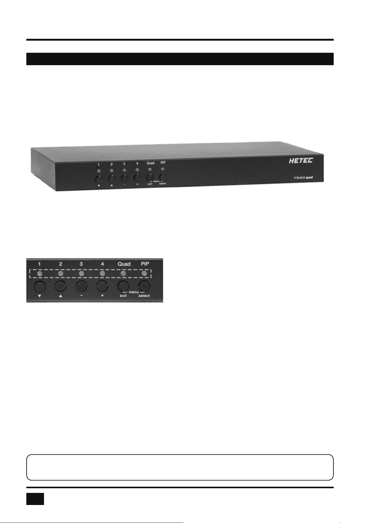
The V-Switch quad front panel has six status indicators (LEDs) and six buttons.
Buttons 1 to 4 switch between channels, LEDs 1 to 4 indicate the status of the individual channels. Quad and
PiP buttons and LEDs are used to switch and indicate display modes and other functions, e.g. call up the OSD
menu etc.
Status LEDs
Front panel
Buttons
Indicators
- LEDs 1 to 4: When these LEDs light up green, the corresponding channel (computer port) has
been selected and is available for keyboard and mouse access. When a LED fl ashes
green, there is no signal at the video input of the selected channel.
A LED lights up yellow when there is a signal at the video input, but another channel
has been selected.
When the LED is dark, there is no signal at the video input and another channel has
been selected.
- LED Quad: When this LED lights up green, the unit is in Quad mode. When the LED is dark,
V-Switch quad operates in Fullscreen mode.
- LED PiP: This LED lights up green when the PiP function is enabled.
LED is dark when the PiP function is off.
Note:
While the OSD menu is open, the active computer can still be operated by mouse.
4
V-Switch quad - Installation and Operation Manual
Page 9
INTRODUCTION
HARDWARE
FRONT PANEL
Buttons
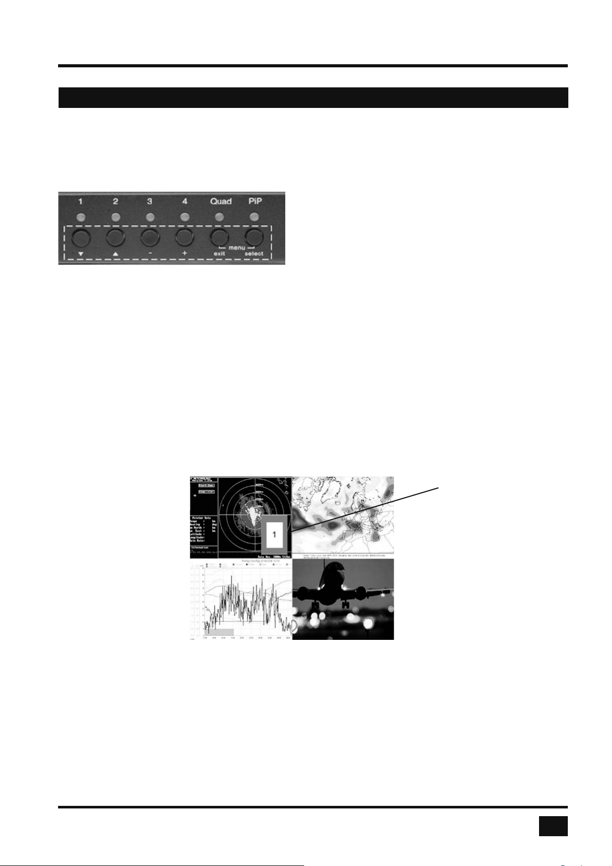
- BUTTONS 1 to 4: These buttons activate the corresponding channel (computer port) and switch
from Quad mode to Fullscreen mode.
In Fullscreen mode, the PiP function remains unchanged.
- Quad BUTTON: Press this button to switch from Fullscreen mode to Quad mode or return to
Fullscreen mode of the last selected channel.
- PiP BUTTON: Press this button to enable or disable the PiP (picture in picture) function in
Fullscreen mode.
Pressing the button in Dual mode switches to Fullscreen mode and back.
Pressing the button in Quad mode opens the channel selector and indicates the
channel whose mouse and keyboard are currently active. Press this button again
to switch from channel to channel as indicated by the selector.
Selector
In Quad mode, the selector can also be opened by pressing hotkey P.
Press hotkey ‘P’ again to switch the active channel (keyboard and mouse
function) from channel to channel as indicated by the selector.
You can also select the active channel using hotkey and the arrow keys .
The selection window closes upon expiry of the channel selection timeout period.
Channel selection timeout is confi gured in OSD under SYSTEM ► QUAD MODE.
Use the “Channel Selection Timeout After:” menu item to defi ne how long the
selector is to be displayed.
V-Switch quad - Installation and Operation Manual
5
Page 10
INTRODUCTION
HARDWARE
FRONT PANEL
Additional button functions
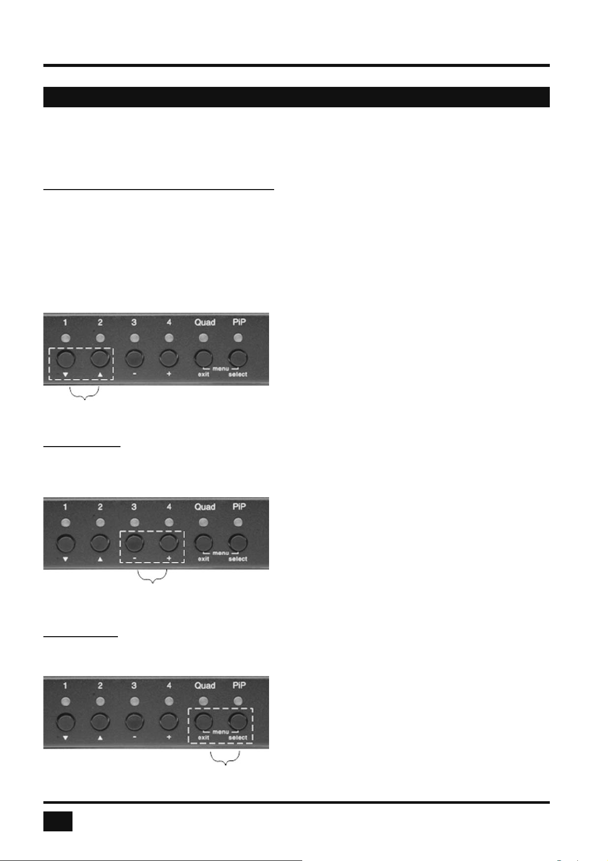
Setting output resolution to safe display modes
To set output resolution to 640 x 480 pixel @ 60 Hz simultaneously press buttons 1 and 2 for longer than 1
second. Use of this feature is recommended when you cannot use the OSD (on screen display dark or illegible)
because the output resolution setting is not supported by the monitor. After setting the correct output resolution
(640x480@60), you can choose a resolution the connected monitor supports in the OSD.
Alternatively, hold buttons 1 and 2 again to cycle through the following four video modes: VGA 640x480@60,
SVGA 800x600@60, XGA 1024x768@60 and UXGA 1600x1200@60.
LEDs 1 to 4 indicate the selected mode.
Resolution VGA, SVGA, XGA and UXGA
Hardware Reset
Press buttons 3 and 4 simultaneously for longer than 4 seconds in order to reset the unit completely (video +
mouse + keyboard) (see also page 7: Reset button)
Note:
Due to the “keep alive” function of keyboard and
mouse, turning power off/on resets only the
video circuit.
Hardware
Reset
Calling up OSD
Simultaneously press Quad and PiP buttons for longer than one second to open the OSD menu.
Note:
While the OSD menu is open, the active computer
can still be operated by mouse.
OSD Menu
6
V-Switch quad - Installation and Operation Manual
Page 11
INTRODUCTION
HARDWARE
REAR PANEL
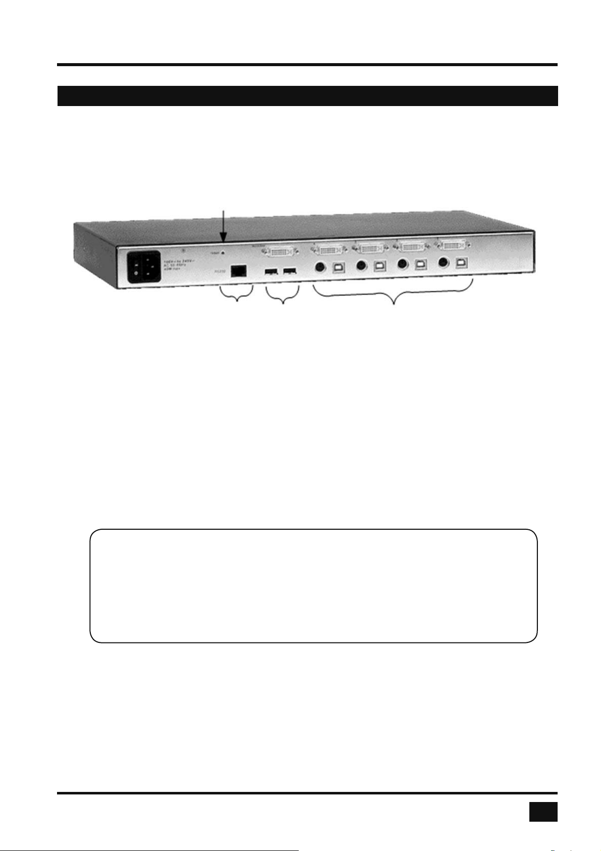
The rear panel of V-Switch quad features four computer ports, the console port (KVM), the serial RS232 port,
the power connection and a reset button.
Reset
Rear panel
Power RS232 Console for each Computer
RJ45 DVI-I DVI-I
2 x USB USB or PS/2
(for keyboard and mouse)
POWER Power Plug
Plug for enclosed power cable.
RESET Button
Press this button, using a suitable pointed object (e.g. ballpoint pen), for a complete reset of V-Switch quad
(video, mouse and keyboard).
Note:
Due to the “keep alive” function of keyboard and mouse, turning power off/on resets
only the video circuit.
If you experience problems with mouse or keyboard, we therefore recommend executing
a complete RESET by either pressing the RESET button on the rear panel or by
simultaneously pressing buttons 3 and 4 on the front panel for longer than 4 seconds
(see page 6 – Hardware Reset).
RS 232 RJ – 45 Port
Connect to this port to access the OSD Menu from a computer using the ConfDev device confi guration
program (see page 64).
The Serial RS 232 port is also used for fi rmware updates (see page 66).
V-Switch quad - Installation and Operation Manual
7
Page 12
INTRODUCTION
HARDWARE
REAR PANEL
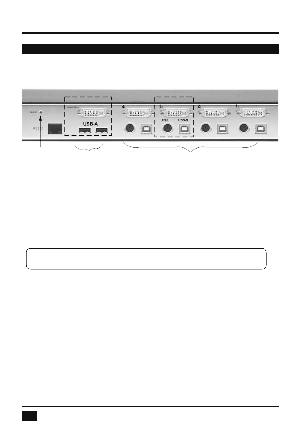
Reset KVM (Console) COMPUTER 1-4
COMPUTER 1 - 4 DVI-I PS/2 (Multi) USB-B
Connect the computer’s keyboard and mouse ports to either the USB or PS/2 port of the V-Switch quad,
as appropriate. For PS/2, use the enclosed Y-PS/2 cable.
KVM (keyboard/video/mouse) DVI-I USB-A USB-A
USB keyboard and mouse are connected to the USB ports. A VGA or DVI monitor can be connected to
the DVI-I connection (use an adaptor cable for VGA).
Using a USB-Hub, you can connect multiple keyboards and mice.
They will work in share mode with an inactivity timeout of 3 seconds.
REMOTE OPERATION
If necessary (depending on distance, quality, infrastructure etc.), you can use HETEC’s KVM extenders
on the KVM port to work remotely over CAT5, fi ber optic or ethernet.
8
V-Switch quad - Installation and Operation Manual
Page 13
INSTALLATION
INSTALLATION
V-Switch quad is best located as close as possible to the computers. This reduces the length of cables and
permits a clearer and more cost-effective installation.
By default, the V-Switch quad is delivered as the desktop version. Using the rack mount kit supplied, it may
also be mounted in a 19” rack. See deliverables page 68.
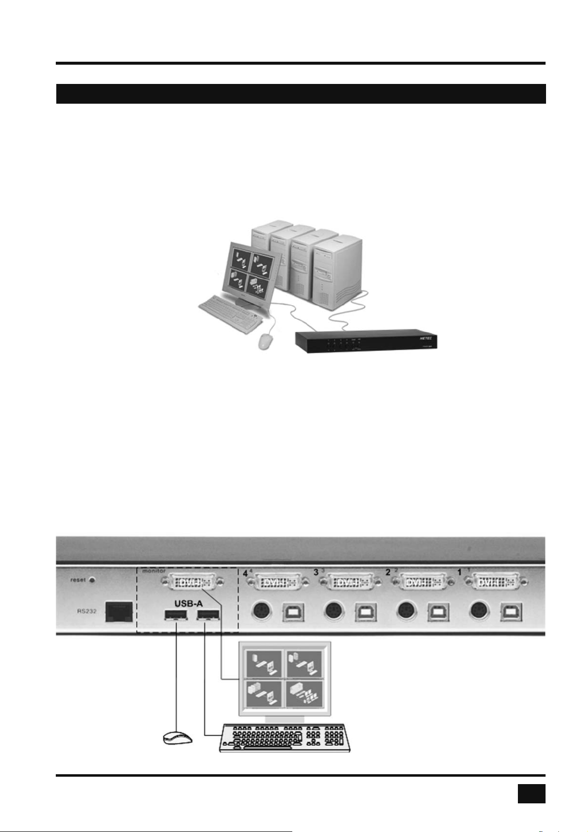
Keyboard, monitor and mouse (console) are connected to the V-Switch quad by means of the corresponding
cables (DVI, USB or PS/2).
For distances greater than 5 m, KVM extenders allow you to work remotely via CAT5, fi ber optic or Ethernet
connection.
Connecting unit to power
- Plug the power cable into the power plug located on the rear panel of V-Switch quad, but do not turn
power on yet.
Connecting console (monitor, keyboard and mouse)
- Connect your monitor to the monitor port of V-Switch quad via VGA-DVI cable (analog) or DVI cable
(digital).
- Connect your USB mouse and keyboard to the USB-A ports on the console.
- PS/2 mouse and keyboard can be connected to V-Switch quad using a PS/2-USB adaptor.
KVM console
with
digital or analog monitor,
USB mouse and USB keyboard
V-Switch quad - Installation and Operation Manual
9
Page 14
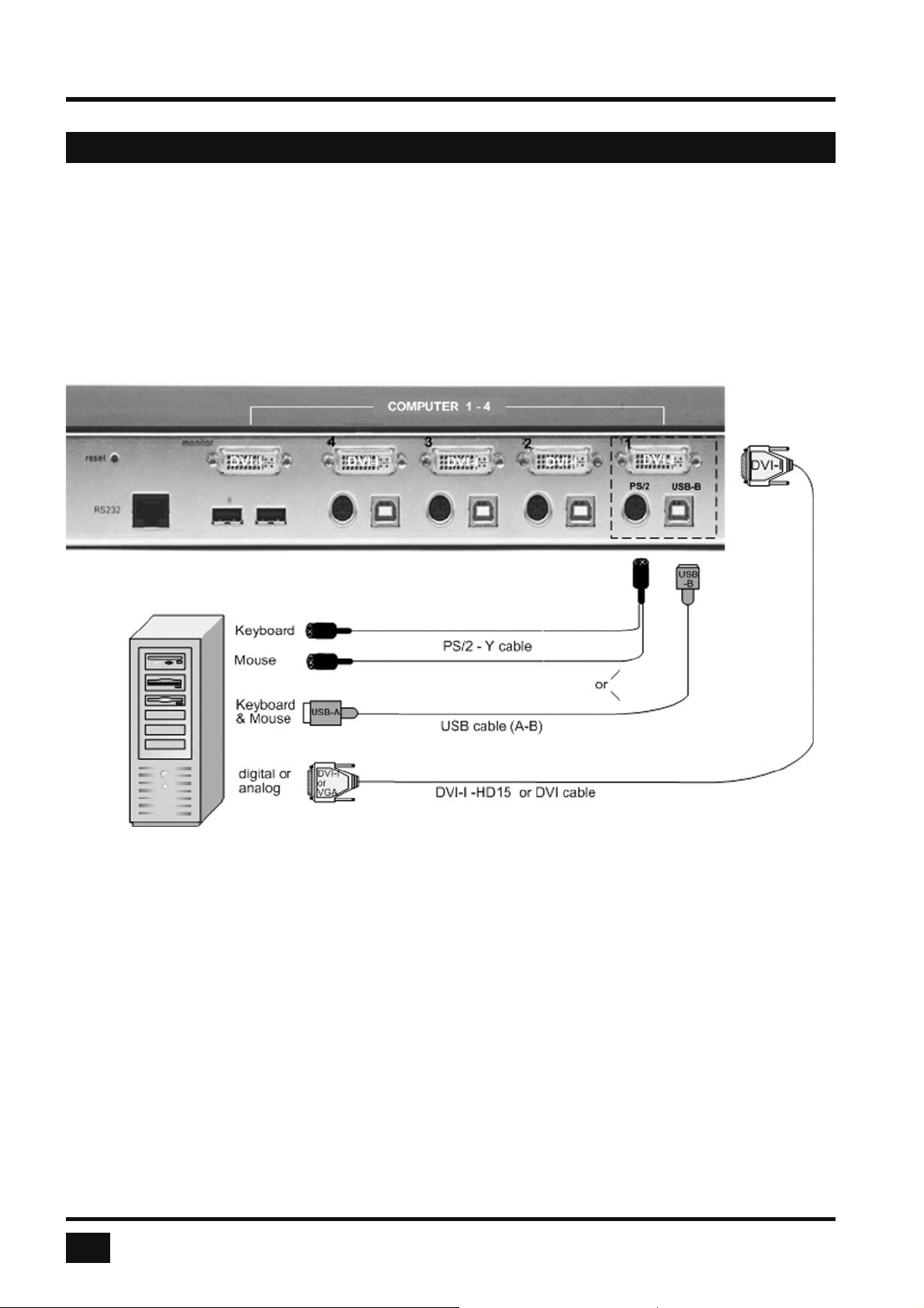
INSTALLATION
INSTALLATION
Connecting the computers
- Switch off the computer and disconnect keyboard, monitor and mouse.
- Connect keyboard and mouse to the computer ports either with a single USB cable or via the PS/2
interface (use the Y cable)
- To connect an analog computer video source (VGA) to V-Switch quad, use a VGA-DVI cable.
Digital video sources are connected via a DVI cable.
Powering up the system
- Switch on V-Switch quad with the power switch on the rear panel. All front panel LEDs light up briefl y
indicating that V-Switch quad is ready for operation. V-Switch quad is now in Quad mode (default).
- Power up all connected computers. V-Switch quad recognizes all input video sources automatically and
displays them on your monitor screen.
- To select another display mode, use the relevant keyboard commands (see pages 11-14) or buttons on the
front panel (pages 5, 6 and 17).
Confi guration
Use either keyboard command hotkey ‘O’ (default setting = CTRL + ALT plus ‘O’) or simultaneously press
Quad and PiP buttons on the front panel of V-Switch quad for longer than one second to call up the OSD main
menu.
All parameter settings are described in chapter OSD.
10
V-Switch quad - Installation and Operation Manual
Page 15
KEYBOARD COMMANDS
KEYBOARD COMMANDS
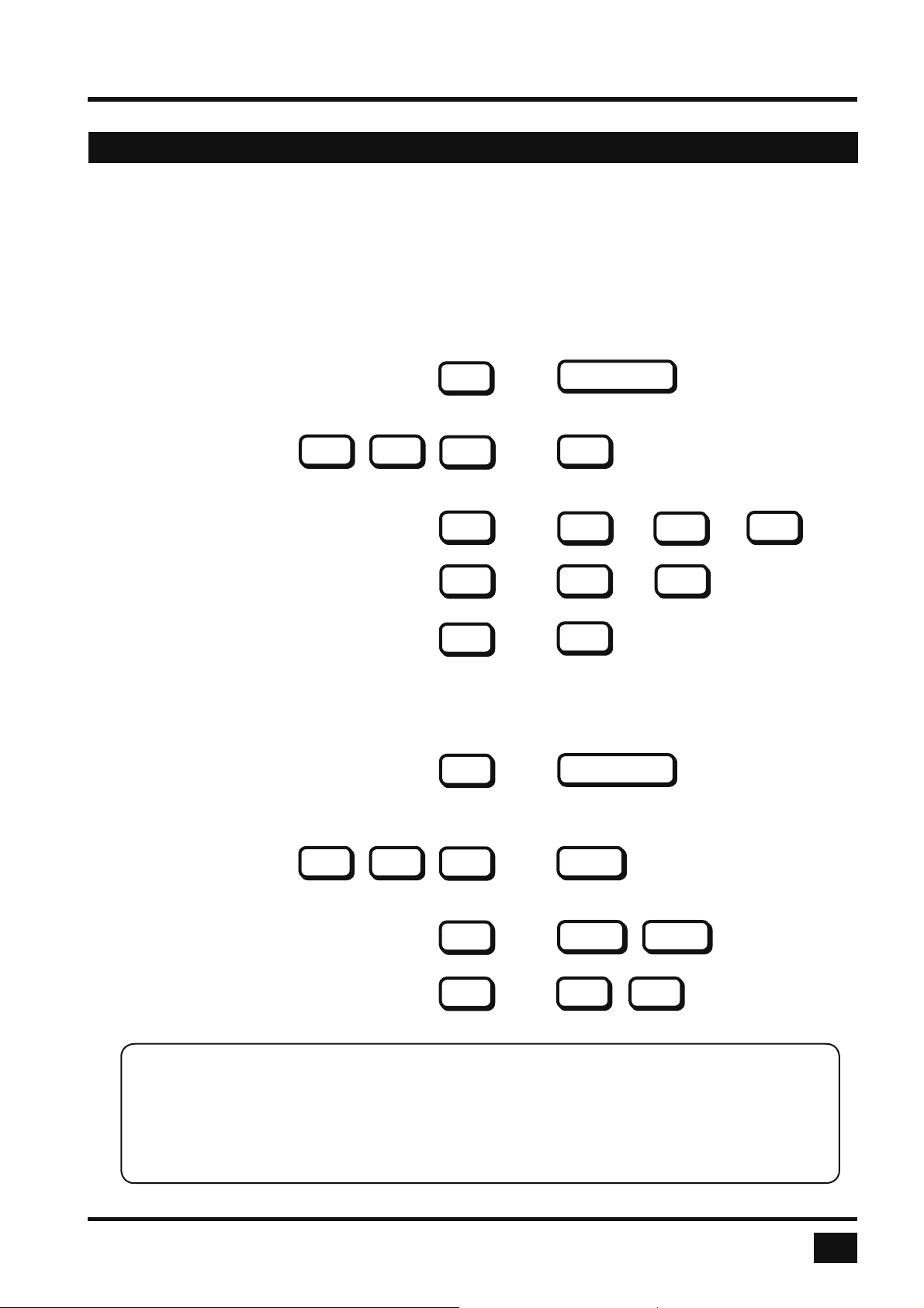
To enter a hotkey command, fi rst activate the command mode. Two types of activation are supported:
multiple hotkey, and double click hotkey.
Use the OSD menu to choose the hotkey type and keys (see page 19). Once in command mode, you can
execute a command.
Multiple Press multiple keys (1 to 4) ( = hotkey ) plus command key.
Hotkey-Command:
COMMAND = Hotkey and together
The following hotkeys are available for selection:
HK
Command Key
Left , , and
Examples: HOTKEY = + +
= +
Double Click Double click one key (=hotkey) and afterwards command key within 2 seconds.
Hotkey-Command:
COMMAND = Hotkey in sequence
For double click hotkey you can choose one of the following keys:
Left , , and
Ctrl
Ctrl
Shift
=
Shift
Alt
HK
HK
HK
HK
Alt
Win
Ctrl
Ctrl
Alt
Command Key
Scroll
Win
Shift
Alt
Examples: HOTKEY =
=
Note:
In command mode (hotkey is activated) two LEDs fl ash on the keyboard.
In double click hotkey mode, pressing an invalid key leaves the command mode.
HK
HK
Scroll Scroll
Ctrl
Ctrl
V-Switch quad - Installation and Operation Manual
11
Page 16
KEYBOARD COMMANDS
KEYBOARD COMMANDS - Multiple Hotkey Commands
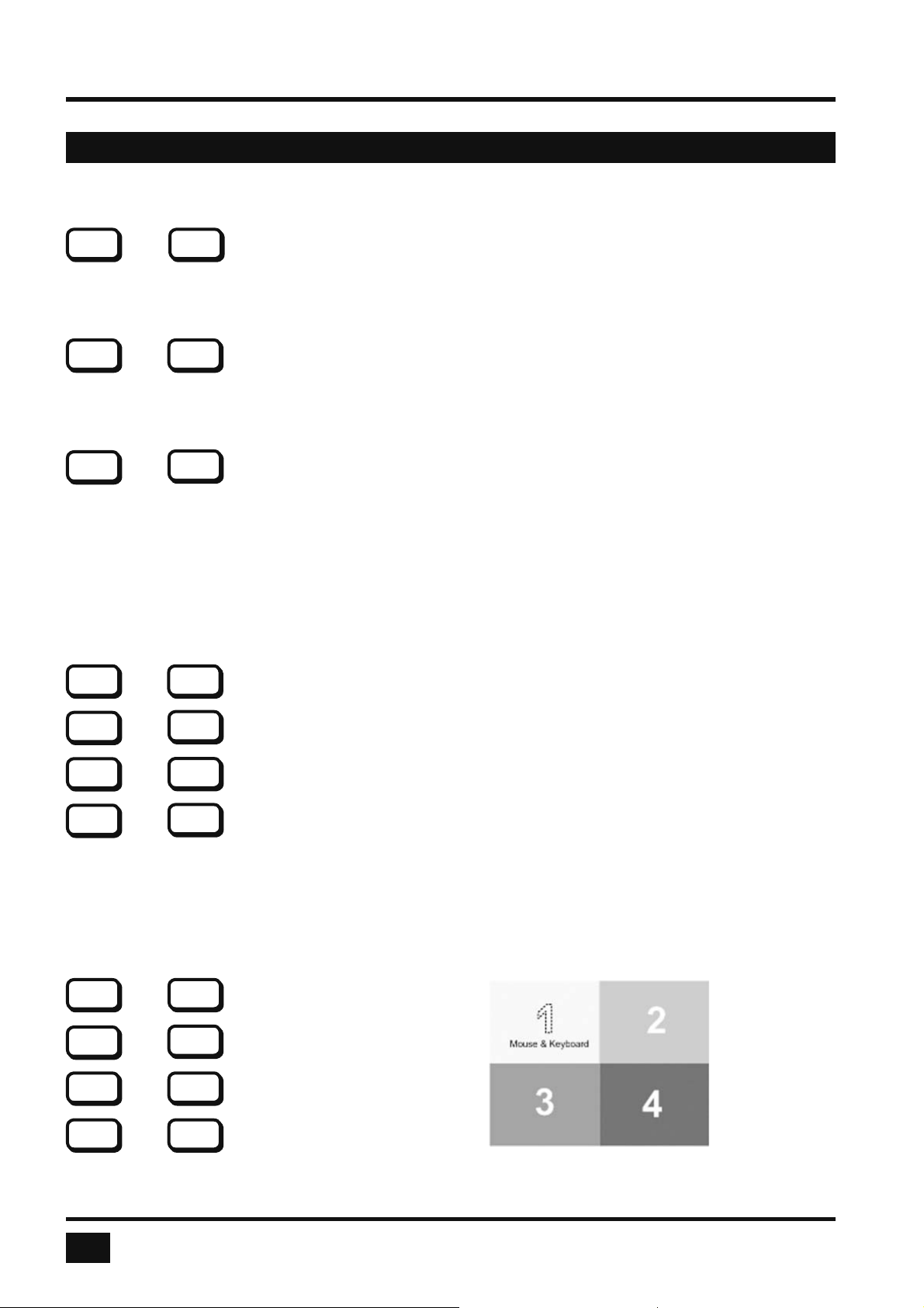
Selecting display mode
HK
+ Quad Mode
Simultaneously press hotkey and ‘Q’ to switch between Quad mode and Fullscreen mode.
HK
+ Fullscreen Mode
In Quad mode, simultaneously press hotkey and ‘F’ to switch the active channel to Fullscreen mode.
+ PiP Function (Fullscreen) / Channel Selection (Quad)
HK
In Fullscreen mode, simultaneously press hotkey and ‘P’ to enable or disable the picture in picture (PiP)
function.
In Quad mode, hotkey and ‘P’ opens the selector. Press hotkey and ‘P’ again to switch the active channel
(keyboard and mouse) from channel to channel as indicated by the selector.
You can also use hotkey and the arrow keys to switch the active channel.
Selecting computer
HK
+ Computer 1 (Fullscreen Mode)
Q
F
P
1
HK
+ Computer 2 (Fullscreen Mode)
HK
+ Computer 3 (Fullscreen Mode)
HK
+ Computer 4 (Fullscreen Mode)
Simultaneously press hotkey and 1, 2, 3 or 4 to switch the corresponding computer to Fullscreen mode and
activate its keyboard and mouse.
In Dual mode you can select the channel on the right using the 1, 2, 3, or 4 keys on the numeric keypad.
Switch the active channel with hotkey and the arrow keys .
Switching in Quad mode and activating channel (keyboard and mouse)
HK
+ Computer 1
HK
+ Computer 2
HK
+ Computer 3
HK
+ Computer 4
Quad display
2
3
4
F1
F2
F3
F4
Simultaneously press hotkey and F1, F2, F3 or F4 to switch to Quad mode and enable mouse and keyboard
of the computer in the respective quadrant.
12
V-Switch quad - Installation and Operation Manual
Page 17
KEYBOARD COMMANDS
KEYBOARD COMMANDS - Multiple Hotkey Commands
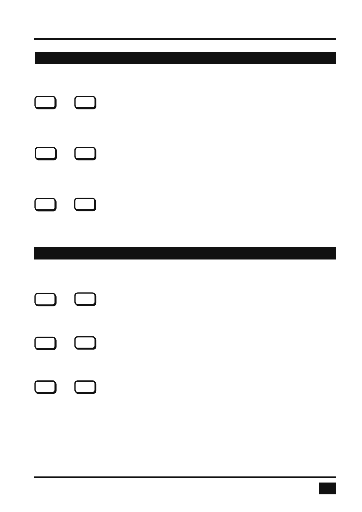
Other Commands
HK O
+ Open OSD
Simultaneously press hotkey and ‘O’ to exit command mode and open the OSD menu (see chapter “On Screen
Display”).
HK
+ Basic output resolution
Simultaneously press hotkey and ‘V’ for longer than 5 seconds to cycle through the following four output video
resolutions: VGA 640x480@60, SVGA 800x600@60, XGA 1024x768@60 and UXGA 1600x1200@60. LEDs
1 to 4 indicate the current resolution.
HK
+ Directly open OSD PiP menu
Simultaneously press hotkey and ‘I’ to call up the OSD PiP menu.
V
I
KEYBOARD COMMANDS - Double Click Hotkey Commands
Selection of Display Mode
HK
Quad Mode
Press hotkey (brief double click on hotkey) followed by ‘Q’, to switch between Quad mode and Fullscreen mode.
Q
Fullscreen Mode
HK
In Quad mode, press hotkey followed by ‘F’ to switch the active channel to Fullscreen mode.
HK
PiP Function (Fullscreen) / Channel selection (Quad)
In Fullscreen mode, press hotkey followed by ‘P’ to enable or disable the picture in picture (PiP) function.
In Quad mode, hotkey and ‘P’ opens the selector. Press hotkey and ‘P’ again to switch the active channel
(keyboard and mouse) from channel to channel as indicated by the selector.
You can also use hotkey and the arrow keys to switch the active channel.
F
P
V-Switch quad - Installation and Operation Manual
13
Page 18
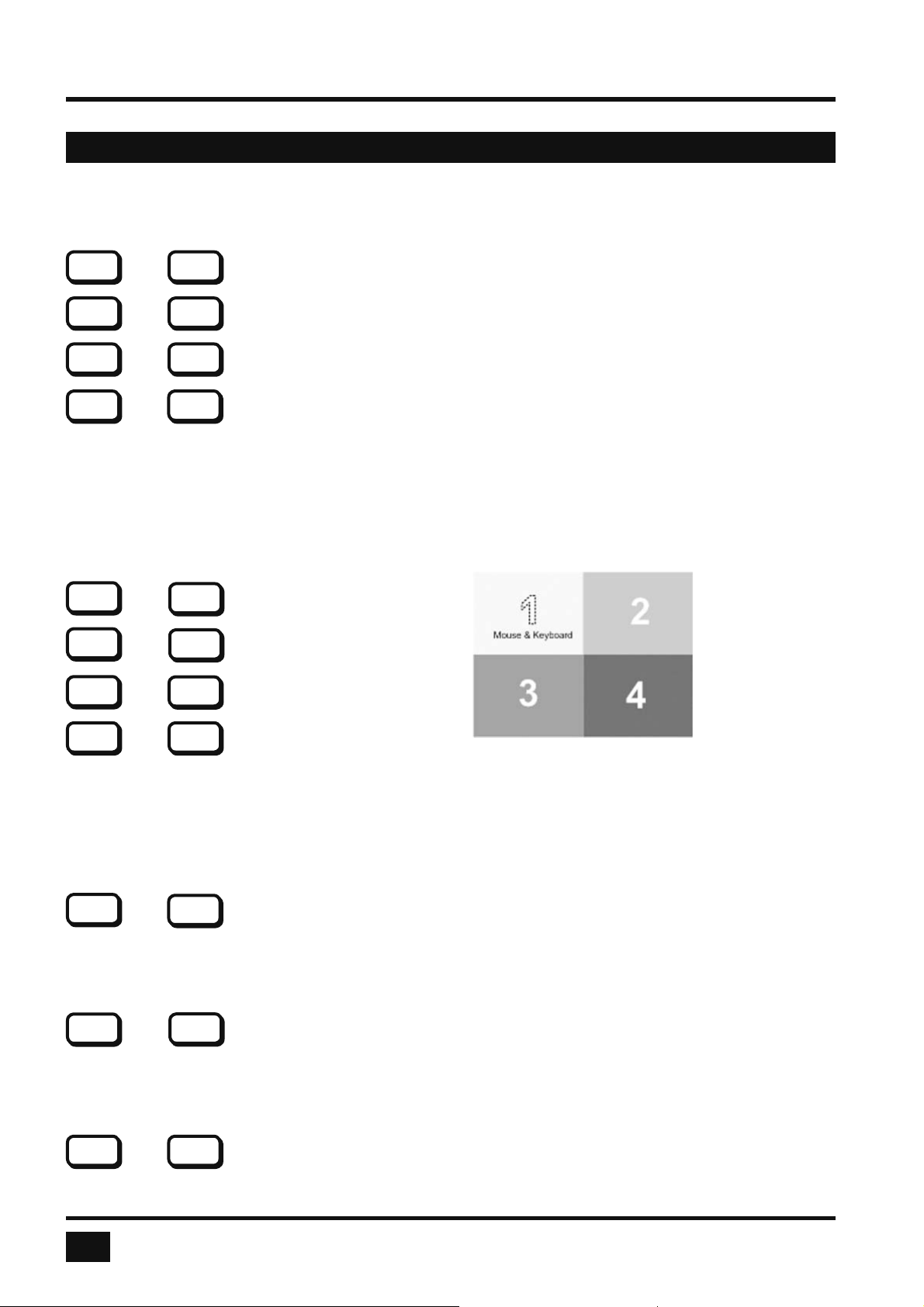
KEYBOARD COMMANDS
KEYBOARD COMMANDS - Double Click Hotkey Commands
Selecting computer
Computer 1 (Fullscreen Mode)
HK 1
Computer 2 (Fullscreen Mode)
HK 2
Computer 3 (Fullscreen Mode)
HK 3
Computer 4 (Fullscreen Mode)
HK
Press hotkey followed by 1, 2, 3 or 4 to switch the corresponding computer to Fullscreen mode and enable its
keyboard and mouse.
In Dual mode you can select the channel on the right using the 1, 2, 3, or 4 keys on the numeric keypad.
Switch the active channel with hotkey and the arrow keys .
Switching in Quad mode and activating channel (keyboard and mouse)
HK
Computer 1
Computer 2
HK
HK
Computer 3
Computer 4
HK F4
Quad display
Press hotkey followed by F1, F2, F3 or F4 to switch to Quad mode and activate mouse and keyboard of the
computer in the respective quadrant.
You can also use hotkey and the arrow keys to switch the active channel.
4
F1
F2
F3
Other Commands
HK
Open OSD
Press hotkey followed by ‘O’ to exit command mode and activate the OSD menu (see “On Screen Display”
chapter).
HK
Basic output resolution
Press hotkey followed by ‘V’ for longer than 5 seconds to cycle through the following four output video
resolutions: VGA 640x480@60, SVGA 800x600@60, XGA 1024x768@60 and UXGA 1600x1200@60. LEDs 1
to 4 indicate the current resolution.
HK I
Directly open OSD PiP menu
Press hotkey followed by ‘I’ to call up the OSD PiP menu
14
O
V
V-Switch quad - Installation and Operation Manual
Page 19
TOUCHSCREEN
Touchscreen Support
Please note that touchscreen support is an optional feature. It is only available for fi rmware versions that
include the confi guration option “TOUCHSCREEN-SUPPORT”. Please see page 67 for a description of
CONFIGURATIONS.
V-Switch quad enables the user to use a touchscreen to control and switch between four computers.
You can fi nd a list of supported models and manufacturers of touchscreens, on our website, www.hetec.de.
To control the V-Switch quad using a touchscreen, connect the touchscreen to the V-Switch quad by
connecting the VGA or DVI cable from the V-Switch quad’s monitor port to the input of the touchscreen.
Connect the USB port of the touchscreen to the V-Switch quad’s console USB port. Please see page 7 for a
description of the V-Switch quad’s ports.
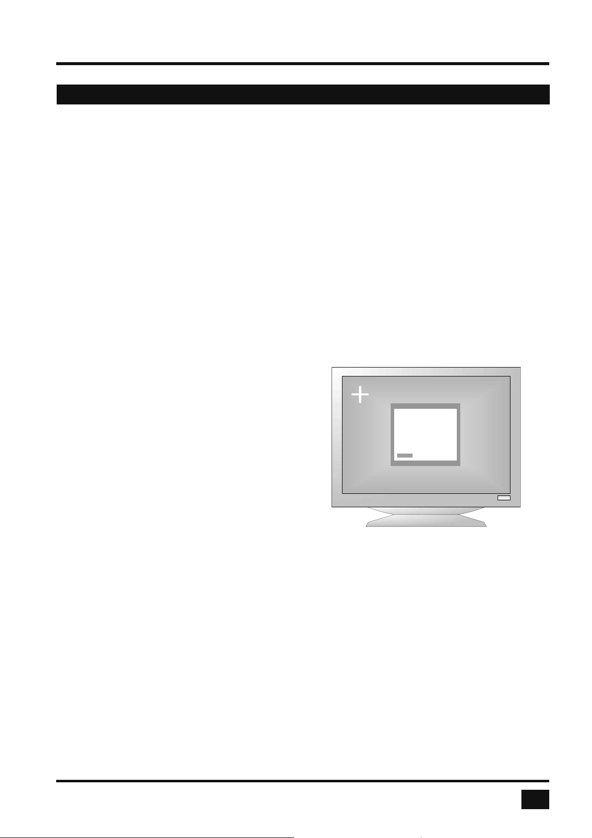
Calibration
After connecting a touchscreen to the V-Switch quad for the fi rst time, calibrate the touchscreen.
To do this, open the CONSOLE ► TOUCHSCREEN menu, choose Calibrate, and press ENTER/SELECT.
An entire description of TOUCHSCREEN menu please see page 46.
Four markers will be displayed in the corners of the
touchscreen. The diagram shows the fi rst marker in the
left top corner of the screen.
Touch the one after the other to complete the calibration.
Touching the center of the markers as accurately as
possible yields best calibration results.
CONSOLE / TOUCHSCREEN
Mouse keyemulation:
>Mouse
Click on touch
Click on release
Enlarge ontouch:
PiP: Yes
Quad: No
Timeout: 5sec
Calibrate
Mouse key emulation
V-Switch quad offers three modes of interpreting the user input as mouse clicks.
Mouse: When touching the touchscreen, the mouse button is pressed.
When the fi nger is released from the touchscreen, the mouse button is released.
This mode can be used for drag and drop operations.
Click on touch: When touching the touchscreen, a mouse click is generated at the position
of the touch.
Click on release: When the fi nger is released from the touchscreen, a mouse click is generated
at the last position of the fi nger.
“Click on touch” and “Click on release” are suited for kiosk applications or environments where touchscreens
are used instead of keyboards and mice, such as in medical industries for hygienic reasons, in industrial
production and automation for operation with gloves, or in vehicles and aircraft where robust components
are required.
V-Switch quad - Installation and Operation Manual
15
Page 20

TOUCHSCREEN
Touchscreen Support
Right mouse button
Press and hold your fi nger on the touchscreen to emulate the right mouse button. This only works in mouse
emulation mode, not in “click on touch” or “click on release”.
Hotmouse and hotmouse menu
To open the hotmouse menu, tap the screen twice, and leave your fi nger pressed on the touchscreen after
the second tap (tap – hold, like a double click without lifting the fi nger on the second click), until the hotmouse
menu opens.
By clicking outside the hotmouse menu, you can open the hotmouse cursor to enlarge and reposition PiPs
(only in PiP mode), and switch channels (see page 20 - 23 for a description of the hotmouse function).
After you are fi nished using the hotmouse cursor, the hotmouse menu will reopen.
Mouse position
Absolute mouse position
V-Switch quad works best together with touchscreens when using absolute mouse positioning mode with the
connected computers. To enable absolute mouse positioning mode, use the menu COMPUTER->MOUSE.
This mode works when a computer is connected via USB, and with most modern operating systems.
Relative mouse position
When using relative mouse positioning, please check the confi guration of the connected computers to ensure
that mouse acceleration is switched off and mouse scaling is set to 1:1. For guides on how to change mouse
acceleration and scaling, please visit www.hetec.de/service/.
Resetting the mouse position
When using relative positioning mode, the actual position of the mouse cursor and the position of your fi nger
on the touchscreen may not match in certain cases when a computer switches resolution or changes the mouse
position (e.g. when the system is confi gured to place the mouse pointer over the ‘OK’ button of a window).
In these cases, to reset the mouse position, either switch to a different channel, and back again,
or tap the touchscreen three times, and leave your fi nger pressed on the touchscreen after the third tap
(tap – tap – hold), until the mouse cursor moves to the top left corner of the screen.
16
V-Switch quad - Installation and Operation Manual
Page 21
ON SCREEN DISPLAY
OSD - MAIN MENU WINDOW
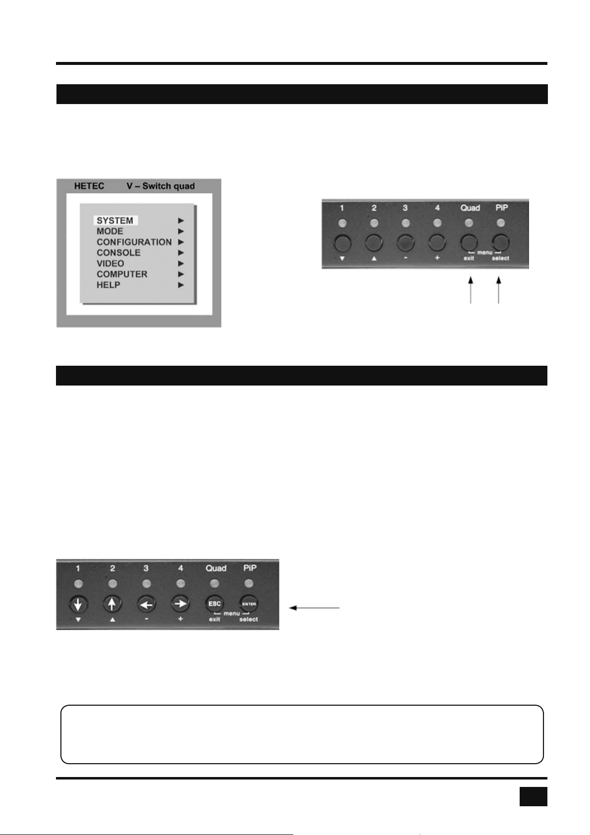
There are two ways to open the main menu (Figure)
- use keyboard command hotkey ‘O’ (see pages 13 and 14) or
- simultaneously press the Quad and PiP buttons on the front panel for longer than one second.
The main menu pops up over the video.
OSD Start
Main Menu
OSD - NAVIGATION
Using the on screen display is simple and easy. To navigate either use the buttons on the front panel or your
keyboard.
a. Navigation with keyboard
To navigate from one fi eld to the next in the OSD menu use the UP and DOWN arrow keys or TAB/SHIFT-TAB
keys. Use the LEFT and RIGHT arrow or + (PLUS) and – (MINUS) keys to change the value in the current fi eld.
Press ENTER to select a menu item.
Press ESC to return to the previous window (higher menu level) or exit the OSD. Changes in parameters are
saved automatically.
b. Navigation using the buttons on the front panel
Corresponding keys on console keyboard
Navigation using the buttons on the front panel is analogous to using the console keyboard. Buttons 1 and 2
correspond to the UP and DOWN arrow keys and buttons 3 and 4 to the LEFT and RIGHT arrow keys or +/-
keys. Confi rm your entry by pressing the PiP / select button.
Press the Quad / exit button to return to the previous page (higher menu level) or exit the OSD. Changed
settings are saved automatically.
Note: Keyboard commands are possible while the OSD window is open.
To activate hotkey commands, use the CTRL key instead of the currently set hotkey (page 19).
V-Switch quad - Installation and Operation Manual
17
Page 22
ON SCREEN DISPLAY
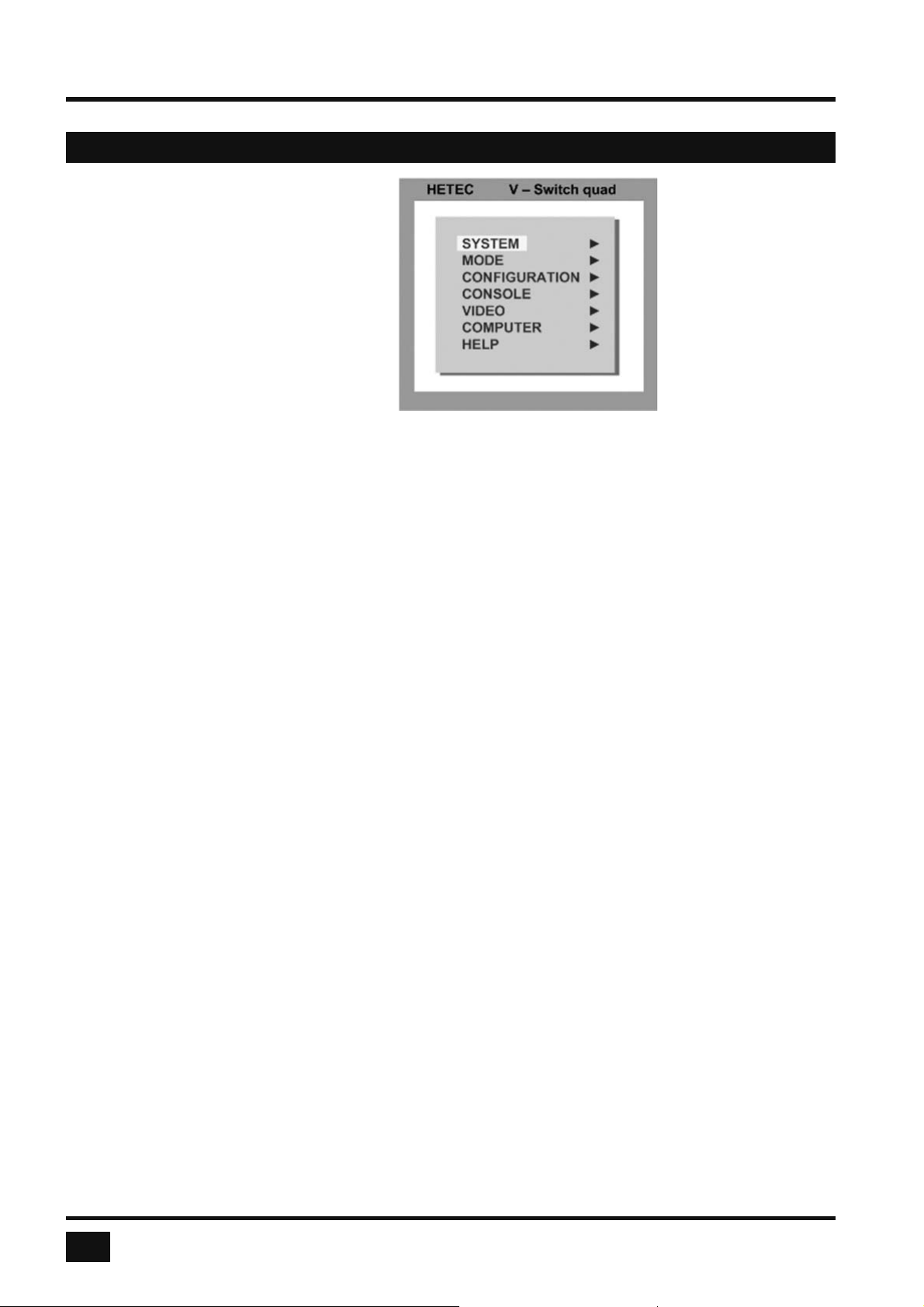
OSD - OVERVIEW
SYSTEM HOTKEY Multiple Hotkey / Double Click Hotkey
HOTMOUSE Hotmouse Recognition, Hotmouse Timeout
QUAD MODE Channel Selection Timeout
OSD POSITION Position of OSD window
OSD LANGUAGE German / English / Spanish
SECURITY Set security level
TEST PATTERN Crosshairs – Color gradient - Rhombus - Rectangle – Stripes
DISABLE CHANNEL Deactivate unused channels
CONTROL* Device control via DCP-XML protocol
MODE PIP (picture in picture) Size, zoom, position and display mode
START Set start confi guration
CONFIGURATION BACKUP Save confi guration settings
RECALL Restore last saved confi guration
FACTORY RESET Reset to factory default settings
CONSOLE VIDEO OUTPUT Video resolution and frequency
KEYBOARD Keyboard layout
TOUCHSCREEN* Set mouse key emulation
MULTI MONITOR Assign mouse/keyboard to video
EDID Read and display EDID data of monitor
VIDEO VIDEO INPUT Display computers’ video input resolutions
Setting: DVI - VGA – VGA/DVI – DVI/VGA
BRIGHTNESS Set brightness of analog input signal
CONTRAST Set contrast of analog input signal
HORIZ POSITION Horizontal screen position
VERT POSITION Vertical screen position
SCREEN WIDTH Set screen width of analog input signal
PHASE Adjust phase of analog input signal
FORMAT Fit input format to screen
COMPUTER KEYBOARD Display type of keyboard (PC1, PC2, PC3 or USB)
MOUSE Display type of mouse (PS/2, PS/2 Wheel or USB)
Set USB mouse positioning (absolute / relative)
RESET Reset PS/2 mouse and keyboard
CHANGE EDID/DDC Program input EDID
HELP COMMANDS List of keyboard commands
INFO Revision Level – Firmware / Hardware
CONTACT Contact Information
*subject to confi guration chosen,
please see page 18 CONFIGURATIONS for details.
18
V-Switch quad - Installation and Operation Manual
Page 23
ON SCREEN DISPLAY
OSD - SYSTEM - HOTKEY
HOTKEY
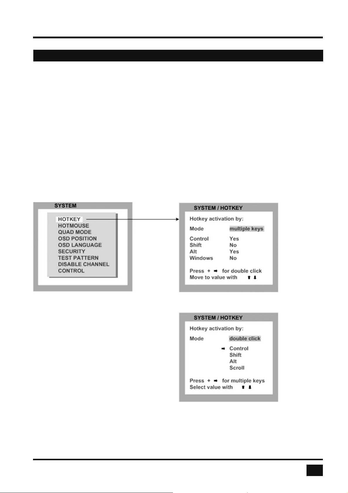
Use the arrow keys to navigate in the SYSTEM menu to the entry HOTKEY and press the ENTER/SELECT
key to open the HOTKEY window.
As described on page 11 under „Keyboard Commands“, two different hotkey modes are available:
- For multiple hotkey commands you can defi ne 1 to 4 keys which are pressed simultaneously to enter the
command mode. Selectable keys are: STRG, SHIFT, ALT and WINDOWS.
- For double click hotkey commands you can choose one key, which is double clicked to enter the command
mode. Selectable keys are: STRG, SHIFT, ALT and SCROLL.
To change the hotkey mode or select another hotkey, navigate with the TAB or ARROW UP/DOWN keys to the
respective fi eld and use the ARROW LEFT/RIGHT or the +/- keys to change the setting.
Multiple
Hotkeys
Double Click
Hotkeys
The command mode is indicated by two fl ashing LEDs on the console keyboard.
Default setting: Multiple Hotkey: CTRL + ALT
V-Switch quad - Installation and Operation Manual
19
Page 24
ON SCREEN DISPLAY
OSD - SYSTEM - HOTMOUSE
HOTMOUSE FUNCTION
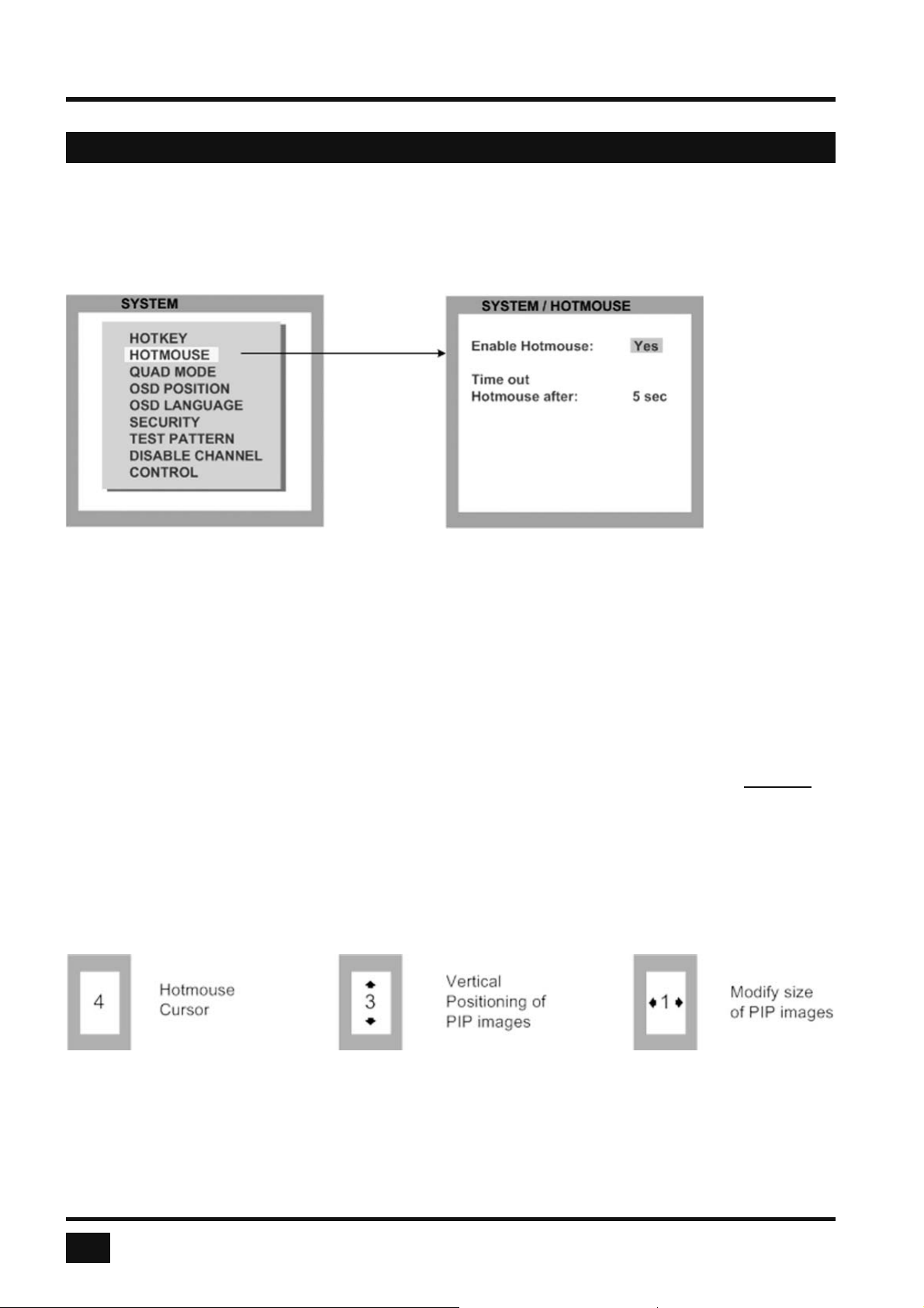
Use the arrow keys to navigate in the SYSTEM menu to the entry HOTMOUSE and press ENTER/SELECT to
open the HOTMOUSE window.
To activate Hotmouse operation, navigate to “Enable Hotmouse” and change the setting to “Yes”.
There are two modes of Hotmouse operation: Hotmouse Cursor and Hotmouse Menu.
While Hotmouse Cursor supports only a limited set of operations, Hotmouse Menu allows execution of all
switch operations and PiP settings.
While the Hotmouse function is activated, the active computer can still be operated by keyboard.
ACTIVATING HOTMOUSE CURSOR
If Hotmouse is enabled (Enable Hotmouse = Yes) move the mouse rapidly four times in alternating horizontal
direction to activate the Hotmouse Cursor.
▬▬► ◄▬▬ ▬▬► ◄▬▬ or ◄▬▬ ▬▬► ◄▬▬ ▬▬►
When using a touchscreen, the hotmouse cursor can be used at any time the hotmouse menu (see page 24)
is open. Touch the screen outside the hotmouse menu to activate the hotmouse cursor.
The Hotmouse Cursor changes its look depending on its position on the screen (arrows in vertical or horizontal
direction, and number of channel).
Use the Hotmouse Cursor to perform the following functions:
in Fullscreen mode: - Switch to another fullscreen channel
in Quad mode: - Select another active channel (keyboard, mouse)
in PiP mode: - Modify position and size of PiP images
- Change active channel
20
V-Switch quad - Installation and Operation Manual
Page 25
ON SCREEN DISPLAY
OSD - SYSTEM - HOTMOUSE
HOTMOUSE CURSOR IN FULLSCREEN MODE
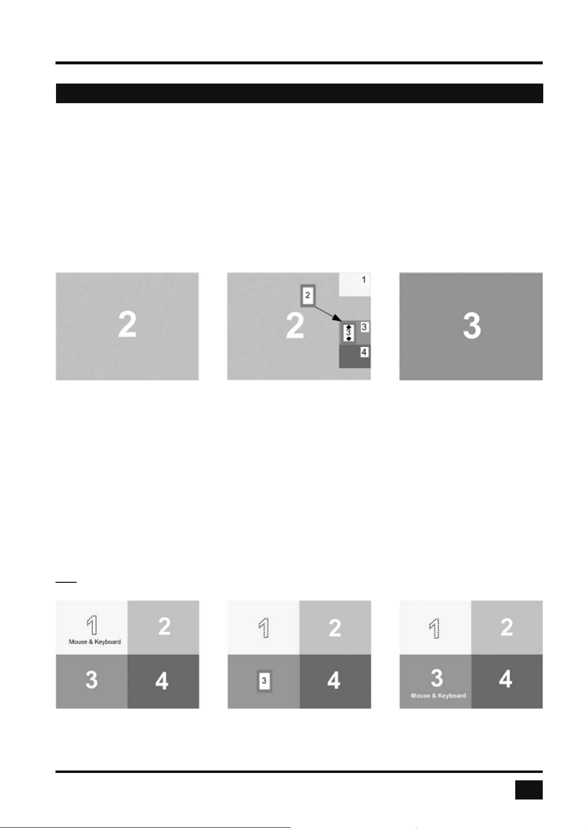
When you activate the Hotmouse Cursor in Fullscreen mode, PiP images of the other channels are temporarily
displayed to allow you to switch to another channel.
Switching to another fullscreen channel
Activate Hotmouse Cursor. Move the Hotmouse Cursor over the PiP image of the channel that you wish to
activate and press the left mouse button.
Example: Switch from channel 2 to channel 3
HOTMOUSE CURSOR IN QUAD MODE
Switching active channel (mouse, keyboard)
Activate Hotmouse Cursor. To change the active channel (switching mouse and keyboard), position the
Hotmouse Cursor in the respective channel fi eld (1 to 4) and press the left mouse button.
Note: When you move into another channel fi eld, the channel number in the Hotmouse Cursor changes.
Example: Switch active channel from 1 to 3
V-Switch quad - Installation and Operation Manual
21
Page 26
ON SCREEN DISPLAY
OSD - SYSTEM - HOTMOUSE
HOTMOUSE CURSOR IN PIP MODE
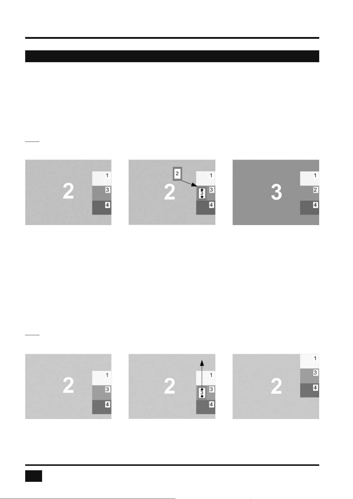
Change active channel
Enable Hotmouse Cursor. Move the Hotmouse Cursor to the PiP-image of the channel you wish to activate
and press the left mouse button.
Note: When the Hotmouse Cursor moves over a PiP-image, its appearance changes (arrows, channel
number).
Example: Switch active channel from 2 to 3
Vertical positioning of PiP images
Activate Hotmouse Cursor. Move the Hotmouse Cursor to the PiP-image area, hold down the left mouse
button and drag the PiPs to the desired vertical position.
Note: As soon as the Hotmouse Cursor moves over a PiP image, its appearance changes
(arrows, channel number).
Example: Move PiP images upwards.
22
V-Switch quad - Installation and Operation Manual
Page 27
ON SCREEN DISPLAY
OSD - SYSTEM - HOTMOUSE
HOTMOUSE CURSOR IN PIP MODE
Modify size of PiP images
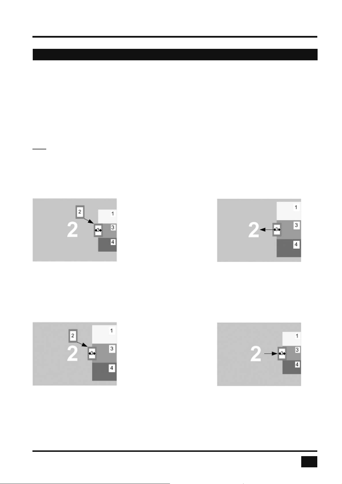
Activate Hotmouse Cursor and move to the left edge of the PiP image area until horizontal arrows appear in the
Hotmouse Cursor. Hold down the left mouse button and drag the Hotmouse Cursor to the left to increase PiP
image size, or to the right to reduce PiP image size.
Note: As soon as the Hotmouse Cursor moves to the left edge of the PiP image area, its appearance changes
(horizontal arrows, channel number).
Scaling PiP images up
Hold left mouse button
Scaling PiP images down
Hold left mouse button
V-Switch quad - Installation and Operation Manual
23
Page 28
ON SCREEN DISPLAY
OSD - SYSTEM - HOTMOUSE
HOTMOUSE MENU - ACTIVATING
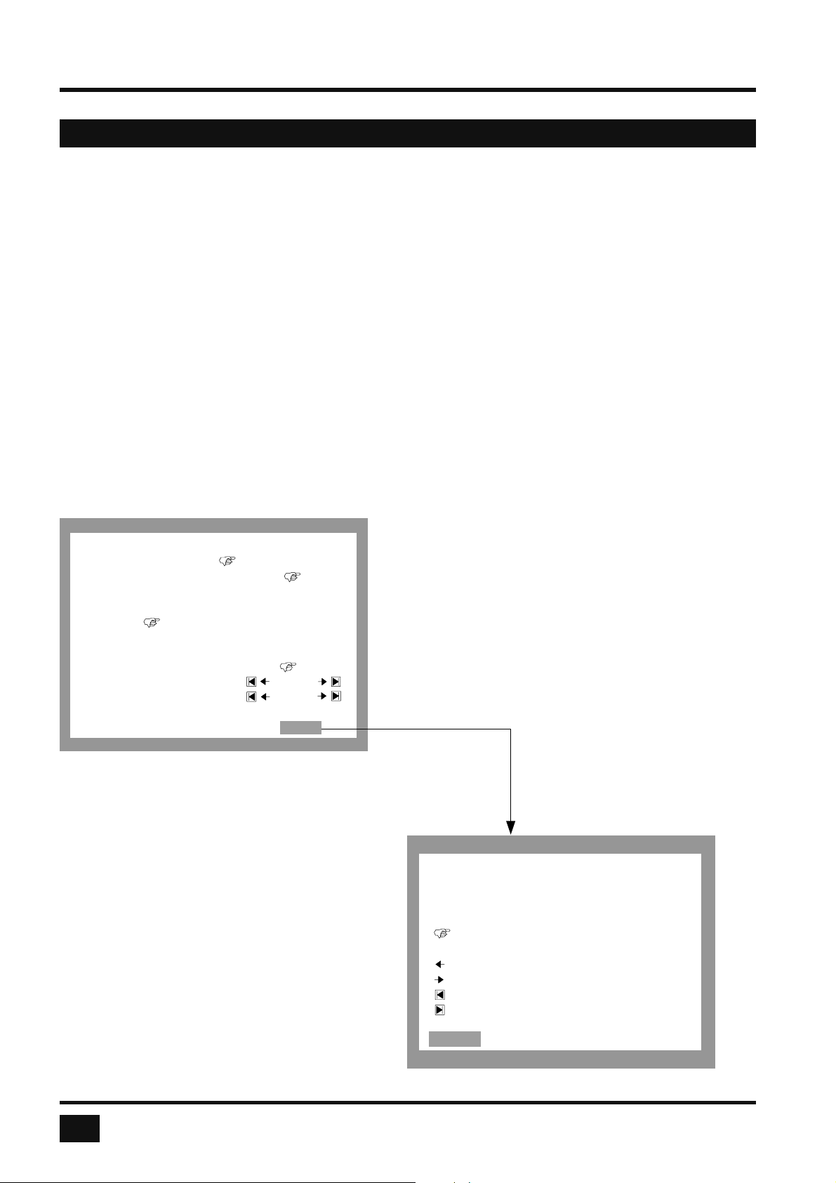
Activate Hotmouse Cursor and press the right mouse button to open the Hotmouse Menu.
To open the hotmouse menu using a touchscreen, tap the screen twice, and leave your fi nger pressed on the
touchscreen after the second tap (tap – hold, like a double click without lifting the fi nger on the second click),
until the hotmouse menu opens.
Menu appearance varies depending on display mode (Quad / Fullscreen / PiP). This menu allows you to carry
out switching operations and change PiP settings:
HOTMOUSE MENU - OPERATING
The Hotmouse Menu allows you to carry out switching operations and to enter PiP settings by mouse click
(left mouse button).
Click Help on the Hotmouse Menu for information on the individual symbols.
HOTMOUSE
The hand symbol ) points to the
Channel: 1 2 3 4
current settings for the active channel,
Mode: quad full PiP
the display mode, and the PiP function.
single: fixed direct
Click on HELP to open the HOTMOUSE
triple: gap no gap
HELP window.
PiP zoom: Yes No
PiP offset: 0 %
PiP size: 15 %
CLOSE HELP
dual scan
tile
Hotmouse menu in PiP-mode
Click with the left mouse button on the arrow
symbols to either increase or decrease the values in
question. Clicking on the I◄ ►I arrow symbols
sets the minimum or maximum value.
HOTMOUSE / HELP
Select active channel.
Select mode.
Select PiP settings.
After having completed the settings, click on CLOSE
to close the Hotmouse Menu window and exit the
Hotmouse Function.
value is selected by
user
decrease value
increase value
set minimum value
set maximum value
CLOSE
Hotmouse Help window
24
V-Switch quad - Installation and Operation Manual
Page 29
ON SCREEN DISPLAY
OSD - SYSTEM - HOTMOUSE
HOTMOUSE MENU - MODES
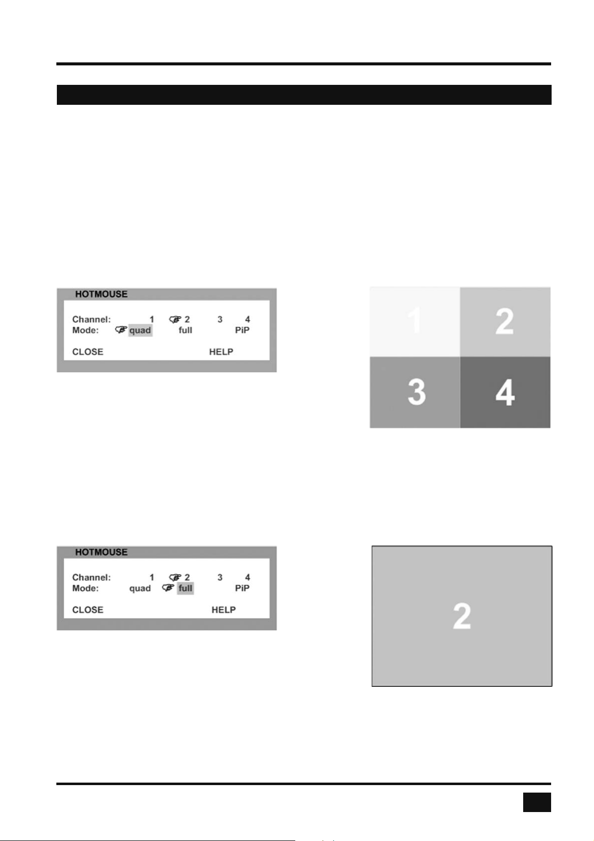
The individual modes can be set as follows:
HOTMOUSE MENU - QUAD MODE
Use the mouse to navigate to a channel in the Hotmouse Menu and click the left mouse button to activate it.
You can also switch to a different mode with the left mouse button.
Hotmouse Menu in Quad mode
Quad mode
HOTMOUSE MENU - FULLSCREEN MODE
Use the mouse to navigate to a channel in the Hotmouse Menu and click the left mouse button to activate it.
You can also switch to a different mode with the left mouse button.
Hotmouse Menu in Fullscreen mode
Fullscreen mode
V-Switch quad - Installation and Operation Manual
25
Page 30
ON SCREEN DISPLAY
OSD - SYSTEM - HOTMOUSE
HOTMOUSE MENU – MODES (continued)
HOTMOUSE MENU – PIP MODE
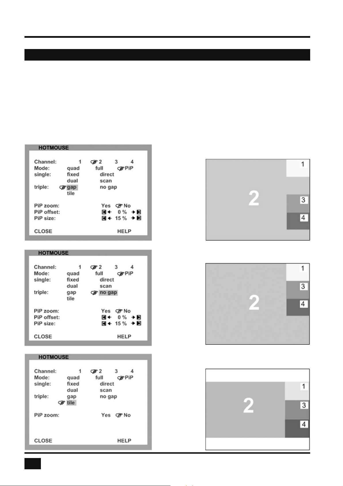
Use the mouse to navigate to a channel in the Hotmouse Menu and click the left mouse button to activate it.
Change position and size of PiP images, and PiP zoom.
Change PiP mode (triple / triple gap / single fi xed / single direct / single scan) and scan time.
The PiP modes are described in detail on page 40.
Triple gap: PiP images are displayed with a gap in place of
the active channel.
Triple no gap: PiP images are displayed without a gap.
Triple tile: The size of the main image and the PiP images is
optimized so that
the main image
and the PiP ima ges are shown as
large as possible
without overlap ping.
26
V-Switch quad - Installation and Operation Manual
Page 31
ON SCREEN DISPLAY
OSD - SYSTEM - HOTMOUSE
HOTMOUSE MENU – PIP MODE (continued)
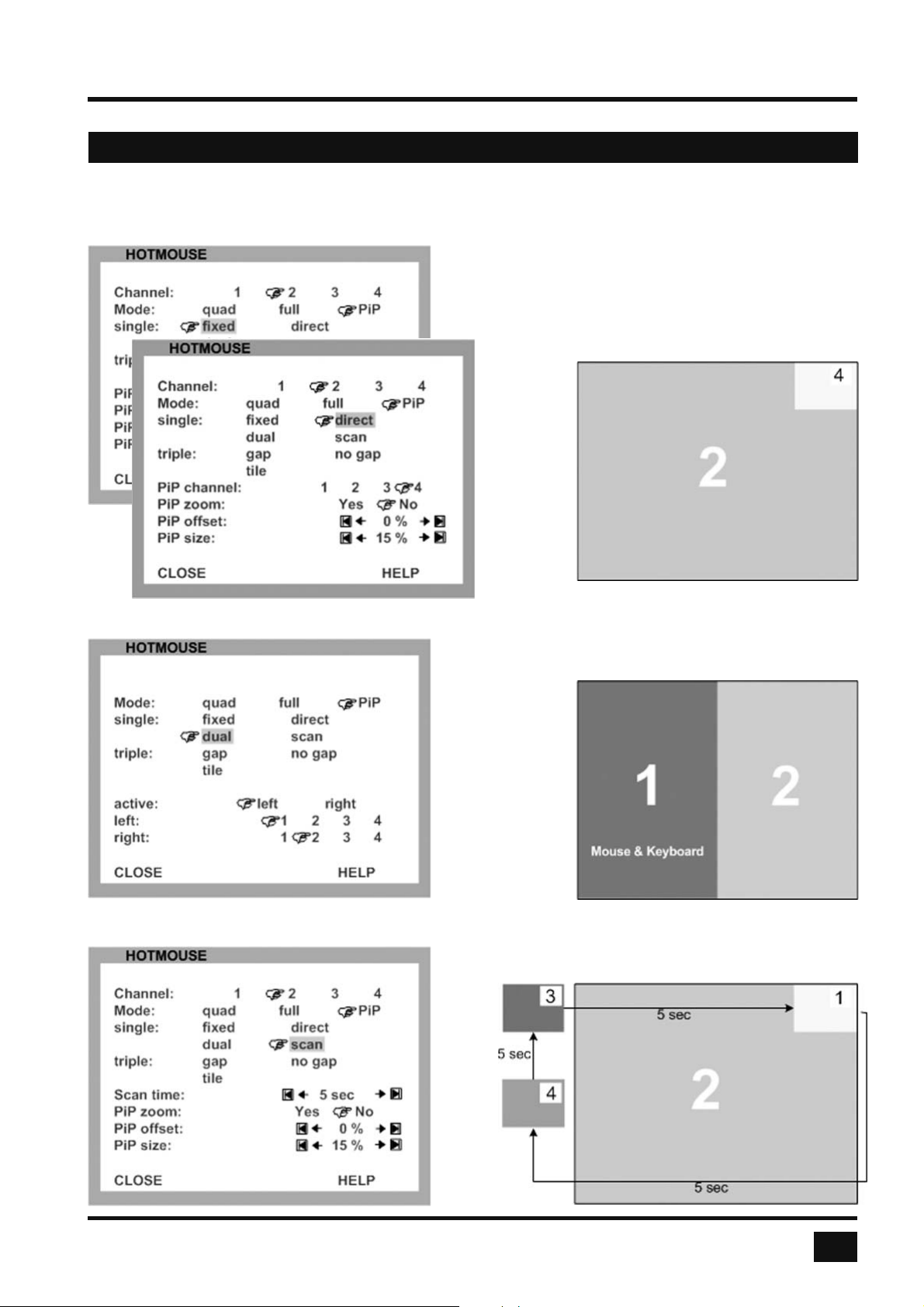
Single fi xed: One selected PiP image is permanently
displayed.
Single direct: Press the front panel buttons 1, 2, 3, or 4
to directly select the PiP channel you want.
Single dual: The left half of the fi rst channel is displayed
at full size next to the left half of the second channel.
Use the „active“
setting to select
the active
channel.
Single scan: Cycles through the PiP images at a set
interval.
V-Switch quad - Installation and Operation Manual
27
Page 32
ON SCREEN DISPLAY
OSD - SYSTEM - QUAD-MODE
QUAD MODE
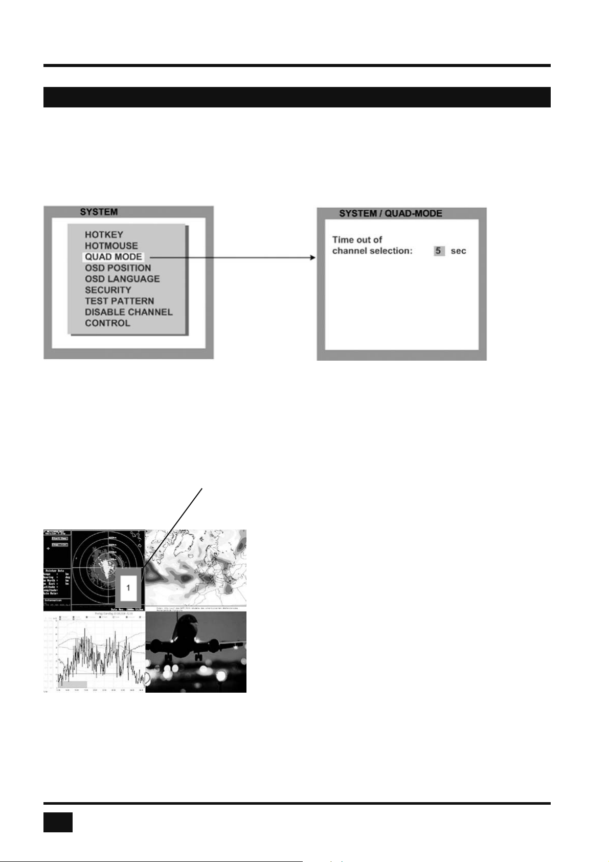
Use arrow keys to navigate in the SYSTEM menu to the entry QUAD MODE and press ENTER/SELECT
to open the QUAD MODE window.
Channel selection timeout defi nes the period (1 to 30 seconds) after which the selector will close automatically.
Default setting is 5 seconds.
Selector
In Quad mode, use hotkey ‘P’ to open the selector.
The selector indicates the active channel (mouse and
keyboard enabled).
Press hotkey ‘P’ again to switch the selector (active channel)
from one channel to the next.
After expiry of the selector timeout, the selector closes.
Alternatively, the selection window can also be opened by
pressing the PiP button on the front panel.
To cycle the active channel, press the PiP button repeatedly.
28
V-Switch quad - Installation and Operation Manual
Page 33
ON SCREEN DISPLAY
OSD - SYSTEM - OSD POSITION / OSD LANGUAGE
OSD POSITION
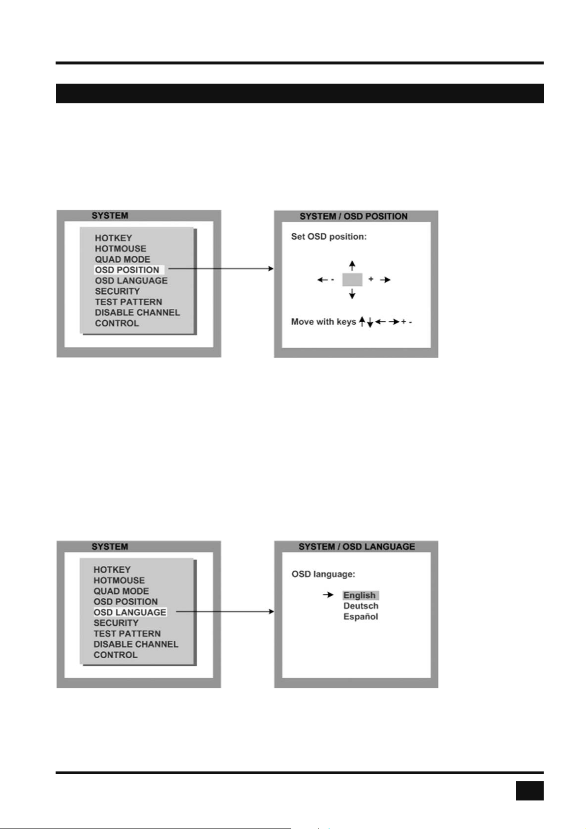
Use arrow keys to navigate in the SYSTEM menu to the entry OSD POSITION and press ENTER/SELECT
to open the OSD POSITION window.
Use this function to move the OSD window to any position on the screen.
OSD LANGUAGE
Use arrow keys to navigate in the SYSTEM menu to the entry OSD LANGUAGE and press ENTER/SELECT
to open the OSD LANGUAGE window.
Set OSD LANGUAGE to either Deutsch (German), Español (Spanish), or English (default: English).
V-Switch quad - Installation and Operation Manual
29
Page 34
ON SCREEN DISPLAY
OSD - SYSTEM - SECURITY
SECURITY – SECURITY LEVELS
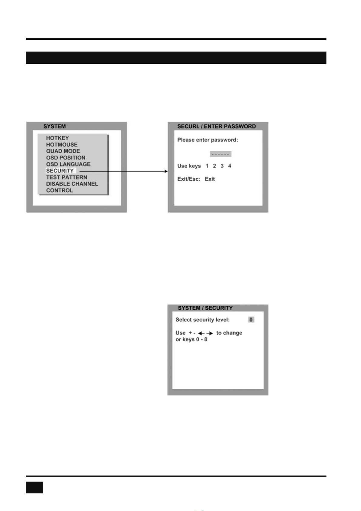
Use arrow keys to navigate in the SYSTEM menu to the entry SECURITY and press ENTER/SELECT to open
the SECURITY window.
The SECURITY feature allows you to reduce the functional range of the V-Switch quad.
Eight security levels are available for this purpose.
By default, all functions are enabled (security level 0). To change the security level, you must fi rst enter a
predefi ned password. This six-digit password is enclosed separately with the deliverables of V-Switch quad
and should only be accessible to authorized persons (administrators etc.).
After entering the password on the keyboard
or front panel (password is not displayed in
password fi eld), the SECURITY window
opens.
Enter the desired security level (0 to 8) under
“Select security level”.
SECURITY LEVEL 0
This is the default setting of the V-Switch quad. All settings are allowed and all functions enabled.
30
V-Switch quad - Installation and Operation Manual
Page 35
ON SCREEN DISPLAY
OSD - SYSTEM - SECURITY
Note:
Before changing the security level, please set the confi guration with which you wish to work in the higher
security level, under MODE ► START (see page 42). This confi guration will be maintained when V-Switch
quad is reset, in case of power failure, or when power is turned off and on again.
SECURITY LEVEL 8
Security level 8 allows you to work only on one channel (computer) in a predefi ned display mode (Quad,
Fullscreen or PiP mode). No settings can be changed, apart from the SECURITY menu item, where you can
change the security level.
SYSTEM SECURITY
SECURITY LEVEL 7
As security level 8, but you can open OSD windows that only show display modes and device settings.
SYSTEM CONTROL
CONSOLE VIDEO OUTPUT/EDID
VIDEO VIDEO INPUT
COMPUTER KEYBOARD/MOUSE/CHANGE EDID/DDC
HELP COMMANDS/INFO/CONTACT
SECURITY LEVEL 6
As security level 7, with the following additional operations:
- Setting of active channel using front panel buttons, hotkeys or hotmouse
- Selecting channel with PiP button in Quad mode
- Changing the directly selectable PiP channel in PiP mode single direct
SECURITY LEVEL 5
As security level 6, with the following additional operations:
- Setting of display mode (Quad / Fullscreen / PiP) using front panel buttons, hotkeys or hotmouse.
SYSTEM TEST PATTERN
V-Switch quad - Installation and Operation Manual
31
Page 36

ON SCREEN DISPLAY
OSD - SYSTEM - SECURITY
SECURITY LEVEL 4
As security level 5, with the following additional settings in the OSD:
SYSTEM OSD POSITION
MODE PIP / START
CONFIGURATION RECALL
VIDEO FORMAT
- Modify PiP settings in Hotmouse menu
- Changing both channels in Dual mode
- Changing the fi xed PiP channel in PiP mode single fi xed
SECURITY LEVEL 3
As security level 4, with the following additional settings in the OSD:
SYSTEM OSD LANGUAGE
VIDEO BRIGHTNESS / CONTRAST / HORIZ POSITION / VERT POSITION
SCREEN WIDTH / PHASE
SECURITY LEVEL 2
As security level 3, with the following additional settings in the OSD:
SYSTEM HOTKEY / HOTMOUSE / QUAD MODE
CONSOLE KEYBOARD
SECURITY LEVEL 1
As security level 2, with the following additional settings in the OSD:
SYSTEM DISABLE CHANNEL
CONSOLE MULTIMONITOR / VIDEO OUTPUT
VIDEO VIDEO INPUT
COMPUTER MOUSE / RESET PS/2
- Switch video output to VGA (using hotkey ‘V’ or front panel buttons 1+2)
32
V-Switch quad - Installation and Operation Manual
Page 37
ON SCREEN DISPLAY
OSD - SYSTEM - TEST PATTERN
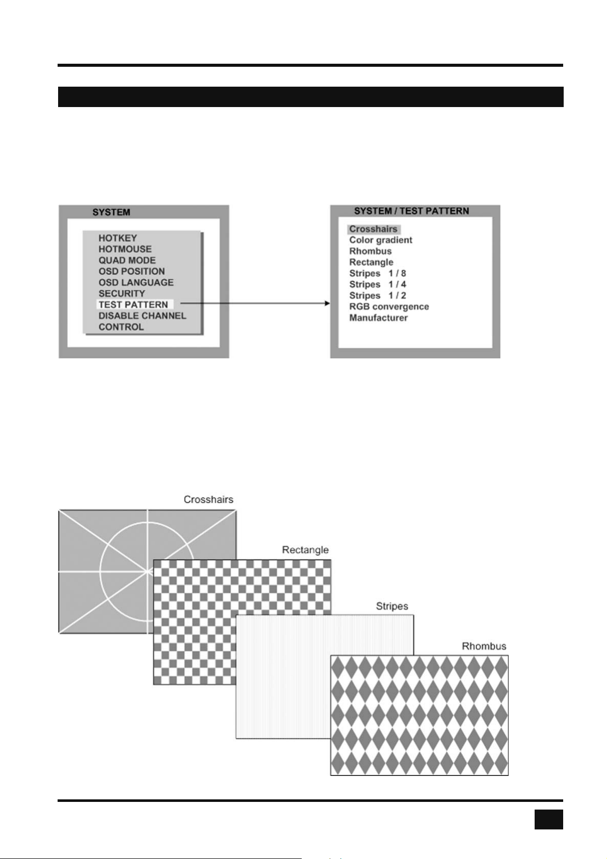
TEST PATTERN
Use arrow keys to navigate in the SYSTEM menu to the entry TEST PATTERN and press ENTER/SELECT to
open the TEST PATTERN window.
Use the Test Pattern feature to check monitor quality (pixel errors, contrast, etc) or the functionality of the
V-Switch quad’s video output.
It is recommended to use all available test patterns for the test procedure.
To exit TEST PATTERN mode, use the front panel buttons or hotkey commands to select a channel.
V-Switch quad - Installation and Operation Manual
33
Page 38
ON SCREEN DISPLAY
OSD - SYSTEM - DISABLE CHANNEL
DISABLE CHANNEL
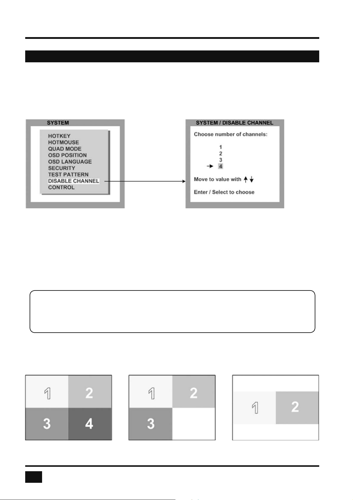
Use arrow keys to navigate in the SYSTEM menu to the entry DISABLE CHANNEL and press ENTER/SELECT
to open the DISABLE CHANNEL window.
If only two or three computers or video sources are connected to V-Switch quad, use the DISABLE CHANNEL
feature to ensure that for the unused channels:
a) message "no signal input x" is not shown in Quad mode
b) PiP images are not displayed on screen
c) these channels are not selectable in Fullscreen mode
For example, if you have connected three computers (channel 1 to 3) to V-Switch quad, use the arrow keys to
navigate to the number 3 and confi rm by pressing ENTER/SELECT.
Note:
To use the “DISABLE CHANNEL” feature, computers/video sources must be connected to
V-Switch quad in ascending order from channel 1 to 4.
Example in Quad mode:
All four channels enabled Three channels enabled Two channels enabled
mid-height
34
V-Switch quad - Installation and Operation Manual
Page 39
ON SCREEN DISPLAY
OSD - SYSTEM - CONTROL
CONTROL
Please note that DCP-XML is an optional feature. This menu is only available for fi rmware versions that include
the confi guration option “DCP-XML”. Please see page 67 for a description of confi guration options.
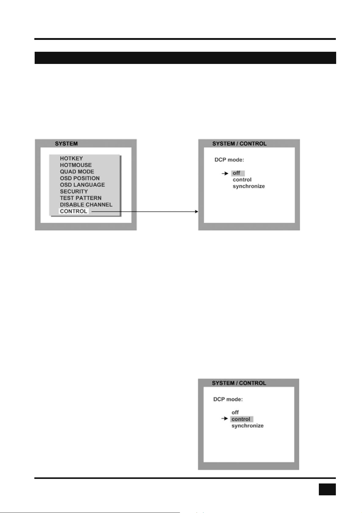
Use arrow keys to navigate in the SYSTEM menu to the entry CONTROL and press ENTER/SELECT to open
the CONTROL window.
HETEC devices can be controlled via DCP (Device Control Protocol), an XML-based protocol.
(See „DCP_Manual.pdf“ on CD.)
There are two DCP modes:
DCP control, which allows external control of the display mode.
DCP synchronize, which keeps several V-Switch quad devices in the same display mode.
Default setting is “off”, which prevents any external CONTROL.
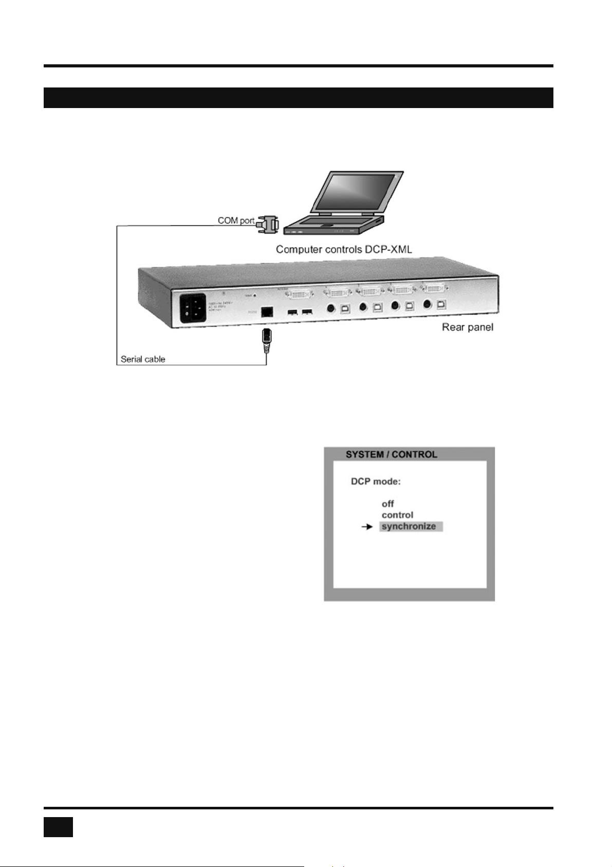
Use a serial cable to connect a control unit to the RS 232 port (RJ 45) on the V-Switch quad rear panel.
To synchronize several devices, special Y cables are required.
Settings for the connection are:
Transfer rate 57600 baud, 8 data bits, no parity, 1 stop bit, no fl ow control
The two control modes operate as follows:
DCP control
This mode allows direct control of a single V-Switch
quad by means of a control device, e.g. a computer.
The control device can query and change the
mode of V-Switch quad.
The V-Switch quad responds to each DCP message
sent by the control device with a DCP reply.
This reply includes the values of all settings queried
or set by means of the last message. If the message
sent by the control unit contains errors, the V-Switch
quad will reply by sending an error message.
V-Switch quad - Installation and Operation Manual
35
Page 40
ON SCREEN DISPLAY
OSD - SYSTEM - CONTROL
Example of DCP control
A V-Switch quad is controlled via
DCP-XML by a computer connected
by serial cable.
For an introduction to the DEVICE CONTROL PROTOCOL please see „DCP_Manual.pdf“ on the CD.
DCP synchronize
Use this mode to keep several V-Switch quad devices
in the same mode.
Every change in settings initiated in the fi rst V-Switch
quad by
Hotkeys,
Hotmouse,
Front panel buttons, or
a controlling device
synchronizes the modes of all connected devices via
DCP messages.
Special serial Y cables are used for this purpose
(see example on page 37)
Important:
Each time you restart a V-Switch quad set to synchronize, it will send all its settings to the next connected
device. This process also takes place after activating synchronize in the OSD menu.
When starting a chain of devices, always start by fi rst switching on the device at the end of the chain.
When the device has completed its startup phase and sent its DCP messages, switch on the next device
in the chain.
Finally, switch on the fi rst device in the chain, which synchronizes the settings of all other devices in the chain
with its own settings as it starts up.
36
V-Switch quad - Installation and Operation Manual
Page 41
OSD - SYSTEM - CONTROL
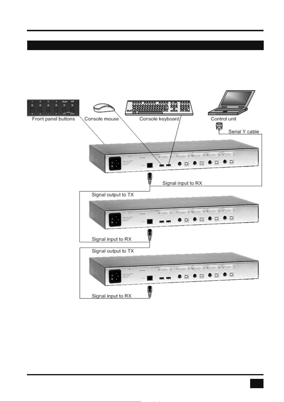
Example of DCP synchronization
V-Switch quad 2 and 3 are synchronized with V-Switch quad 1.
V-Switch quad 1
ON SCREEN DISPLAY
V-Switch quad 2
V-Switch quad 3
To synchronize, V-Switch quad 1 sends every change in settings as a DCP message via the serial Y cable to
the RX input of V-Switch quad 2.
V-Switch quad 2 adopts the settings and sends a DCP message via TX output over the Y cable to the RX
input of V-Switch quad 3.
The synchronization chain can have any length.
Do not connect the last device in the chain to the fi rst device (i.e. do not create a loop).
V-Switch quad - Installation and Operation Manual
37
Page 42

ON SCREEN DISPLAY
OSD - SYSTEM - CONTROL
SECURITY LEVELS
The security level settings in the OSD menu described on page 30 also apply to control via DCP messages.
Queries are possible up to security level 7.
The table below shows the maximum security levels for simple element settings. These settings may be
changed via DCP up to the specifi ed protection level.
Maximum security level for:
CONSOLE CHANNEL 6
VIDEO CHANNEL 6
VIDEO LAYOUT 5
PIP LAYOUT 4
PIP SIZE 4
PIP OFFSET 4
PIP ZOOM 4
PIP CHANNEL 4
DUAL CHANNELS (L/R) 6
PIP SCAN TIME 4
38
V-Switch quad - Installation and Operation Manual
Page 43
ON SCREEN DISPLAY
OSD - MODE - PIP
PiP (Picture in Picture Function)
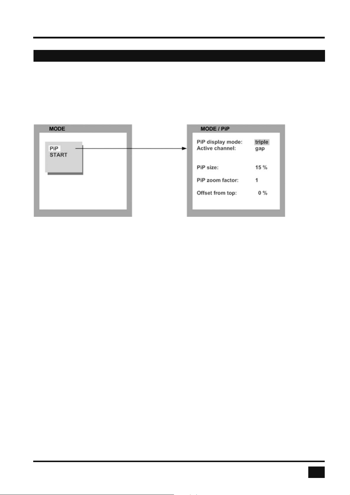
Use arrow keys to navigate in the MODE menu to the entry PIP and press ENTER/SELECT to open the PIP
window.
In the PIP window you can confi gure PiP size, position, and display mode.
PiP size
Adjust the size of PiP images to your requirements. 12 (singe mode) or 9 (triple mode) different sizes are
available:
Single: 3 % - 5 % - 7 % - 10 % - 15 % - 20 % - 25 % - 28 % - 33 % - 38 % - 44 % - 50 %
Triple: 3 % - 5 % - 7 % - 10 % - 15 % - 20 % - 25 % - 28 % - 33 %
50 % equals the size of one quad screen (one quarter of a full size screen).
PIP zoom factor
Use this option to zoom the center of the PiP images by a factor of 2.
Offset from top
Use this option to change the position of PiP images. PiP images can be moved vertically to any position on the
screen’s right hand margin.
V-Switch quad - Installation and Operation Manual
39
Page 44
ON SCREEN DISPLAY
OSD - MODE - PIP
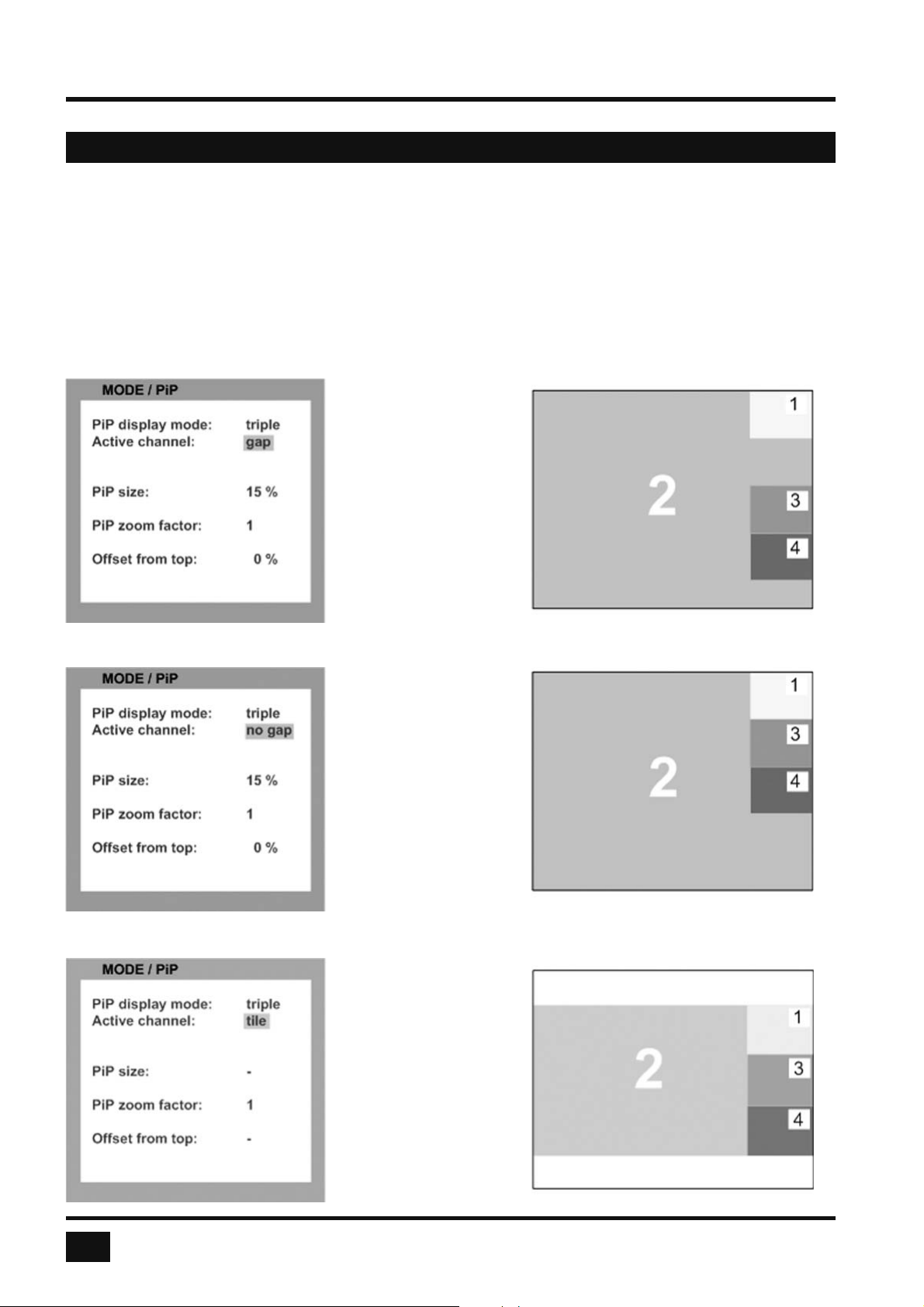
PIP Display Mode
V-Switch quad offers the following PiP modes:
PIP display mode triple: all other video sources are displayed (three PiP images)
Triple gap:
PiP images are displayed
with a gap in place of the
active channel.
Triple no gap:
PiP images are displayed
without a gap.
Triple tile:
The size of the main image
and the PiP images is
optimized so that the main
image and the PiP images
are shown as large as
possible without
overlapping.
40
V-Switch quad - Installation and Operation Manual
Page 45
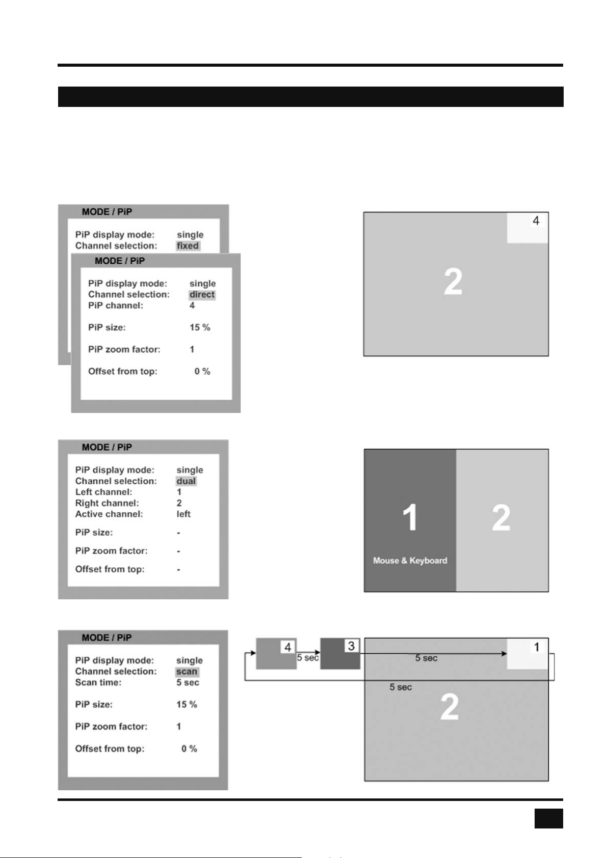
OSD - MODE - PIP
PIP Display Mode (continued)
PIP display mode single: One PiP image is displayed.
You can choose between different display modes:
Single fi xed:
One selected PiP image
is permanently displayed.
Single direct:
Press the front panel
buttons 1, 2, 3, or 4 to
directly select the PiP
channel you want.
ON SCREEN DISPLAY
Single dual:
In Dual mode the left
halves of the fullscreen
images from two video
sources are displayed
side by side.
You can choose the left
or the right image as the
active channel.
Single scan:
Within a PiP image, the
three other video sources
are displayed one after the
other; the delay can be set
to between one and nine
seconds.
V-Switch quad - Installation and Operation Manual
41
Page 46
ON SCREEN DISPLAY
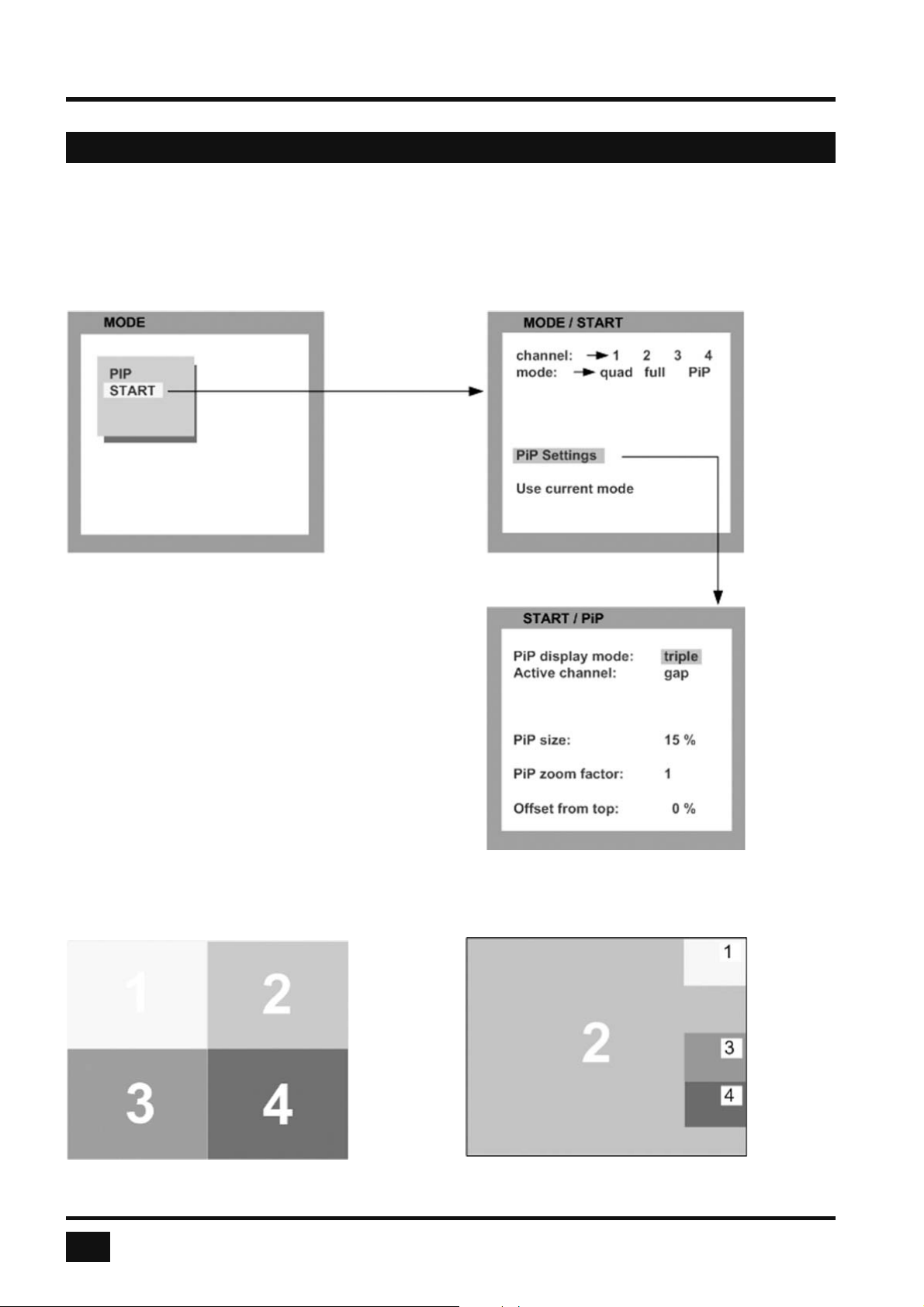
OSD - MODE - START
START (Set start confi guration)
Use arrow keys to navigate in the MODE menu to the entry START and press ENTER/SELECT to open the
START window.
This feature allows you to defi ne the start confi guration,
i.e. the display mode (Quad, Fullscreen, or PiP), active
channel, and PiP settings which V-Switch quad uses
after a reset or when the system is powered up.
When the START menu is called up, the current
start confi guration is displayed. To modify your start
confi guration, change parameters in the channel,
mode, and PiP fi elds. Press ESC to save the new
parameters and exit the START menu.
Choose “Use current mode” to adopt the
current settings as start mode. Use arrow keys to
navigate to “Use current mode” and confi rm by
pressing ENTER.
The factory default start mode is Quad.
Default start screen Example of a start screen confi guration
42
V-Switch quad - Installation and Operation Manual
Page 47
ON SCREEN DISPLAY
OSD - CONFIGURATION - BACKUP
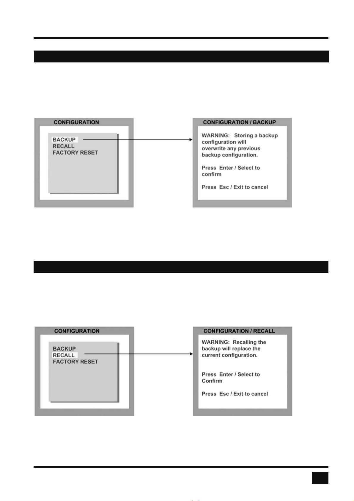
BACKUP
Use arrow keys to navigate in the CONFIGURATION menu to the entry BACKUP and press ENTER/SELECT
to open the BACKUP window.
This function saves the current device settings, including the start mode set in MODE START.
OSD - CONFIGURATION - RECALL
RECALL
Use arrow keys to navigate in the CONFIGURATION menu to the entry RECALL and press ENTER/SELECT
to open the RECALL window.
Use this feature to replace the current settings with the last confi guration saved using the BACKUP command.
V-Switch quad - Installation and Operation Manual
43
Page 48
ON SCREEN DISPLAY
OSD - CONFIGURATION - FACTORY RESET
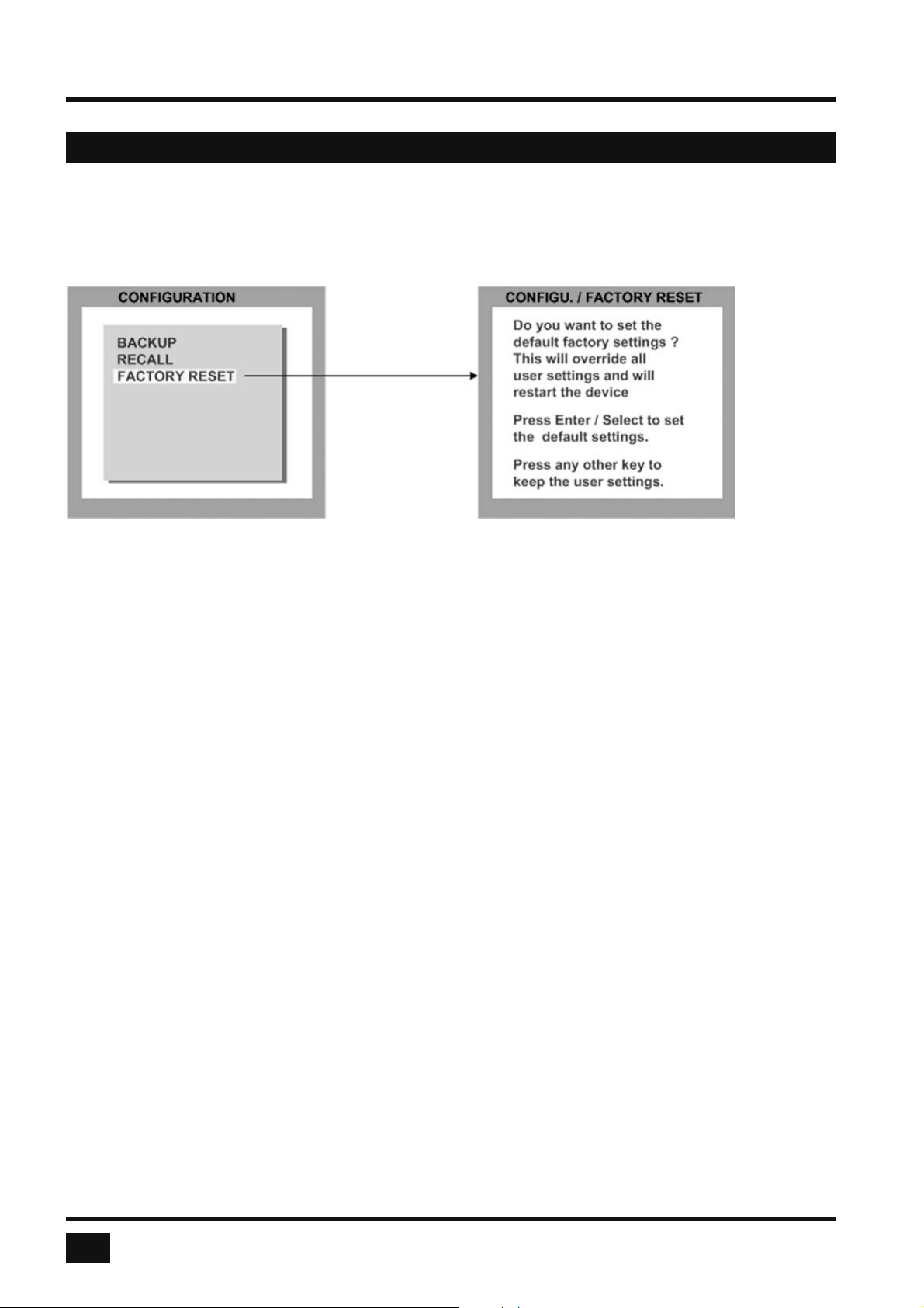
FACTORY RESET
Use arrow keys to navigate in the CONFIGURATION menu to the entry DEFAULTS and press ENTER/SELECT
to open the DEFAULTS window.
Use this function to reset the V-Switch quad to its default settings. If necessary, save your current settings
before using the DEFAULTS command. Execution of this command results in a complete reset and reboot of the
V-Switch quad with factory defaults.
FACTORY DEFAULTS:
SYSTEM HOTKEY = Multiple Hotkey / Hotkey = Ctrl + Alt
HOTMOUSE = ON / Hotmouse timeout = 5 sec.
QUAD MODE Channel selection timeout = 5 sec.
OSD POSITION = centered
OSD LANGUAGE = English
SECURITY = None (security level = 0)
DISABLE CHANNEL = All four channels are active
CONTROL = Off
MODE PIP = Size = 15 % Zoom factor = 1
Display mode = triple Active channel = gap;
Offset from top = 0 %
Start confi guration = Quad / active channel = 1
CONSOLE VIDEO OUTPUT = auto
KEYBOARD = English
MULTI MONITOR = Monitor 1 --> Channel 1; Monitor 2 --> Channel2;
Monitor 3 --> Channel 3; Monitor 4 --> Channel4;
VIDEO VIDEO INPUT = DVI / VGA (all channels)
BRIGHTNESS = 58.2 % (all channels)
CONTRAST = 63.5 % (all channels)
HORIZ POSITION = auto (all channels)
VERT POSITION = auto (all channels)
SCREEN WIDTH = +0 (screen-width correction of all channels)
PHASE = +0 (all channels)
FORMAT Fit to screen = No (all channels)
COMPUTER MOUSE USB mouse positioning = relative (all channels)
44
V-Switch quad - Installation and Operation Manual
Page 49
ON SCREEN DISPLAY
OSD - CONSOLE - VIDEO OUTPUT
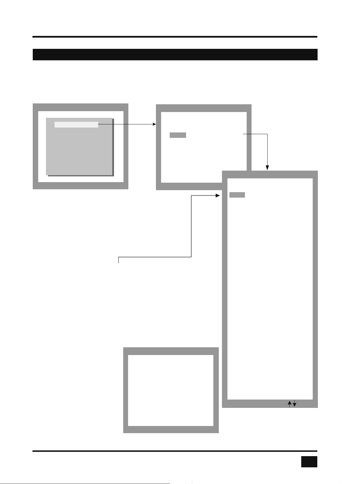
VIDEO OUTPUT
Use arrow keys to navigate in the CONSOLE menu to the entry VIDEO OUTPUT and press ENTER/SELECT to
open the VIDEO OUTPUT window.
CONSOLE
Change with ENTER/SELECT
VIDEO OUTPUT
KEYBOARD
TOUCHSCREEN
MULTI MONITOR
EDID
Use the VIDEO OUTPUT menu to choose an output
resolution supported by your monitor.
Press ENTER/SELECT to enter the selection menu.
Use arrow keys to select the desired line in the list
shown on the right and press ENTER/SELECT
for the new video format.
When the output mode is set to ‘auto’, the V-Switch quad
chooses a resolution by reading the connected monitor’s
EDID data. Choose the EDID menu item to check whether
the connected monitor provides this data.
If the monitor does not offer this data, V-Switch quad sets
VGA mode (640x480@60Hz) as default and activates
Sync on Green.
Sync on Green can be deactivated on V-Switch quad models
produced in 2006 or later (CPLD Version 43).
MODE / TEST
The new output mode is visible
for 10 seconds.
Within this time you can either
You have chosen a new
output resolution. It will
be tested for 10 seconds.
accept the new setting by
pressing ENTER/SELECT or
return to your original setting
by pressing ESC/EXIT.
Press Enter / select to
accept the setting.
Press any other key to
keep the old setting.
CONSOLE / VIDEO OUTPUT
mode horiz vert Hz
UXGA 1600 x 1200 60
Sync on Green: No
EDID
mode horiz vert Hz
auto
VGA 640 x 480 60
VGA 640 x 480 75
VGA 640 x 480 85
SVGA 800 x 600 60
SVGA 800 x 600 75
SVGA 800 x 600 85
XGA 1024 x 768 60
XGA 1024 x 768 70
XGA 1024 x 768 75
XGA 1024 x 768 85
SXGA 1280 x 1024 50
SXGA 1280 x 1024 60
SXGA 1280 x 1024 75
UXGA 1600 x 1200 50
UXGA 1600 x 1200 60
UXGAr 1600 x 1200 50
UXGAr 1600 x 1200 60
XGA/B 1152 x 864 75
UWXGA 1280 x 960 60
UWXGA 1280 x 960 85
SUN 1152 x 900 66
WXGA 1280 x 768 60
WXGA 1366 x 768 60
WUXGA 1920 x 1200 40
WUXGA 1920 x 1200 50
WUXGA 1920 x 1200 60
HDTVp 1280 x 720 50
HDTVp 1280 x 720 60
HDTVp 1920 x 1080 24
HDTVp 1920 x 1080 50
HDTVp 1920 x 1080 60
Press Enter / Select or
VIDEO OUTPUT / MODE
V-Switch quad - Installation and Operation Manual
45
Page 50
ON SCREEN DISPLAY
OSD - CONSOLE - KEYBOARD / MULTI MONITOR
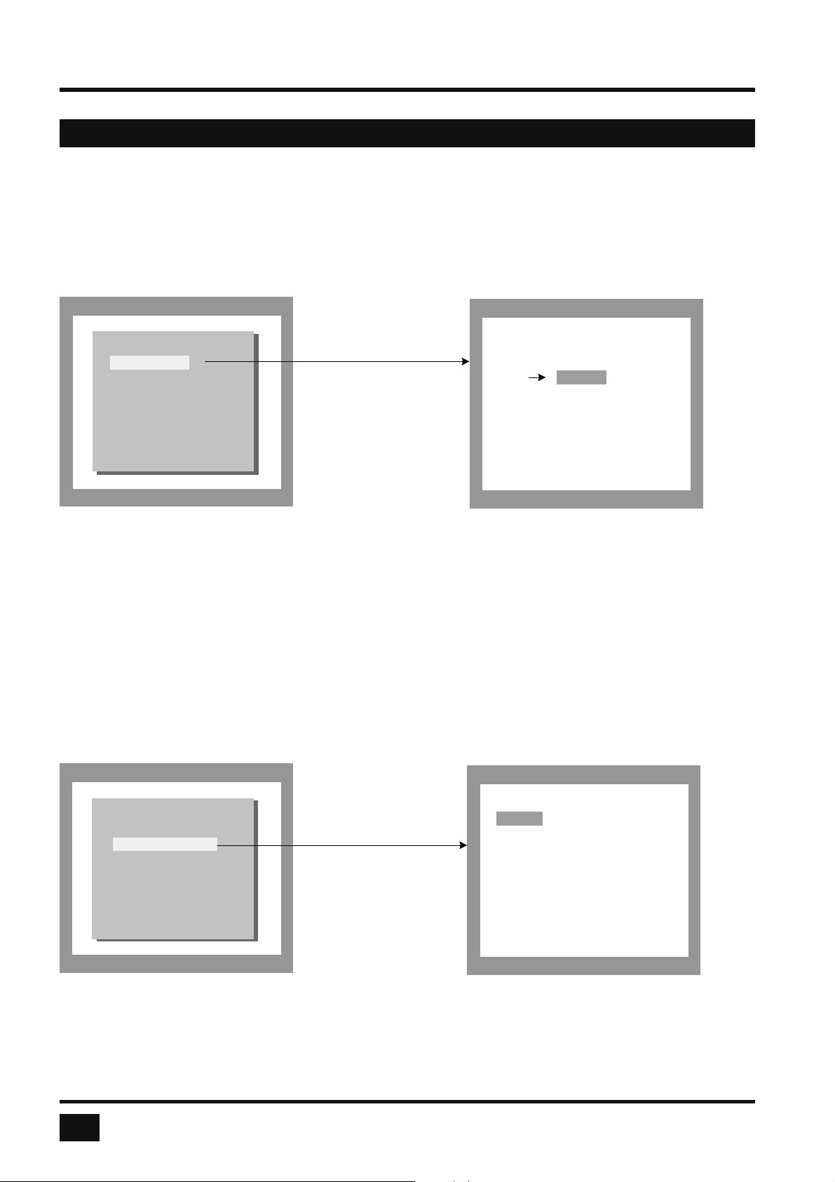
KEYBOARD
Use arrow keys to navigate in the CONSOLE menu to the entry KEYBOARD and press ENTER/SELECT to
open the KEYBOARD window. Set the keyboard layout to the desired language, English, Deutsch (German),
Español (Spanish), Français (French), or Italiano (Italian).
CONSOLE
VIDEO OUTPUT
KEYBOARD
TOUCHSCREEN
MULTI MONITOR
EDID
CONSOLE / KEYBOARD
Console keyboard language:
English
Deutsch
Español
Français
Italiano
TOUCHSCREEN
Please note that touchscreen support is an optional feature. This menu is only available for fi rmware
versions that include the confi guration option “Touchscreen-Support”. Please see page 67 for a description
of CONFIGURATIONS.
Use arrow keys to navigate in the CONSOLE menu to the entry TOUCHSCREEN and press
ENTER/SELECT to open the TOUCHSCREEN window.
46
CONSOLE
VIDEO OUTPUT
KEYBOARD
TOUCHSCREEN
MULTI MONITOR
EDID
V-Switch quad - Installation and Operation Manual
CONSOLE / TOUCHSCREEN
Mouse key emulation:
> Mouse
Click on touch
Click on release
Enlarge on touch:
PiP: Yes
Quad: No
Timeout: 5 sec
Calibrate
Page 51

ON SCREEN DISPLAY
OSD - CONSOLE - TOUCHSCREEN
In the CONSOLE ► TOUCHSCREEN menu, you can set the following options:
Mouse key emulation
The following three types of mouse emulation can be chosen:
Mouse: When touching the touchscreen, the mouse button is pressed.
When the fi nger is released from the touchscreen, the mouse button is released.
This mode can be used for drag and drop operations.
Click on touch: When touching the touchscreen, a mouse click is generated at the position
of the touch.
Click on release: When the fi nger is released from the touchscreen, a mouse click is generated
at the last position of the fi nger.
“Click on touch” and “Click on release” are suited for kiosk applications or environments where touchscreens
are used instead of keyboards and mice, such as in medical industries for hygienic reasons, in industrial
production and automation for operation with gloves, or in vehicles and aircraft where robust components
are required.
Enlarge on touch
PiP: If this option is set to Yes, touching a PiP switches to the PiP’s channel.
If set to No, you can control the computer in the PiP without switching channels.
Touching the PiP also switches mouse and keyboard to that channel.
Touching the full screen channel switches keyboard and mouse back to the full
screen channel.
Quad: If this option is set to Yes, touching a channel in Quad mode enlarges it to full screen.
The channel remains in full screen as long as the user controls the computer with
touchscreen, mouse and keyboard.
After the user is inactive for a certain time, the device switches back to Quad mode.
Use the Timeout setting to set the timeout.
If you switch on PiP mode, and then return to Quad mode, the V-Switch quad will go to PiP mode instead of full
screen mode when you touch a quadrant in Quad mode.
When you switch modes with the front panel buttons, the keyboard hotkeys, or the hotmouse menu, the new
mode will remain set, and will not switch back to Quad mode automatically.
As soon as you switch back to Quad mode, you can again temporarily enlarge quadrants by touching them.
V-Switch quad - Installation and Operation Manual
47
Page 52
ON SCREEN DISPLAY
OSD - CONSOLE - TOUCHSCREEN / MULTI MONITOR
Timeout
If the V-Switch quad is confi gured to enlarge quadrants on touch in Quad mode, this setting controls how
long the device remains in full screen mode when there is no more user activity before switching back
to Quad mode.
Calibrate
Start touchscreen calibration (see page 15 Touchscreen support). Calibration is recommended after fi rst
connecting a touchscreen.
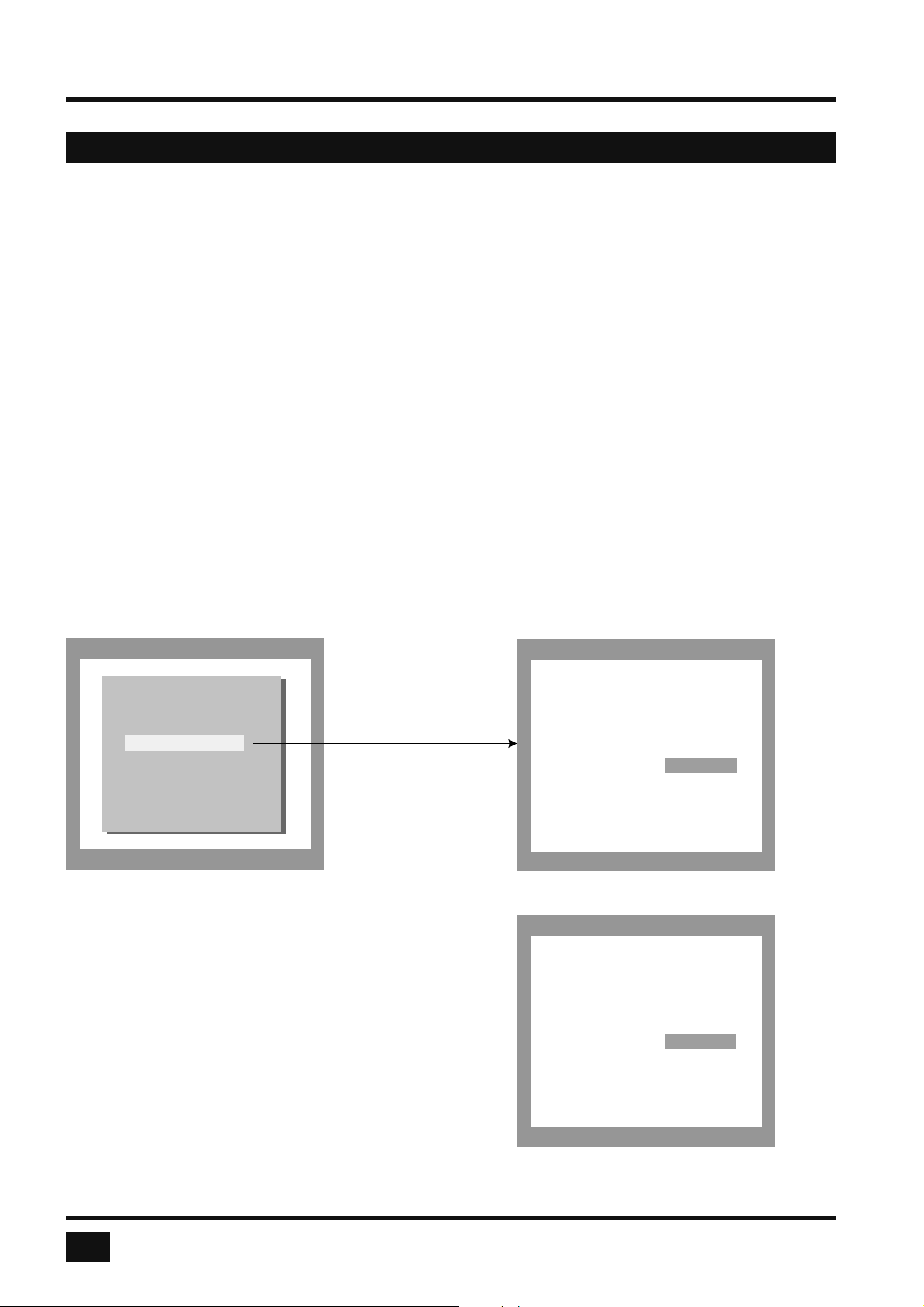
MULTI MONITOR
Use arrow keys to navigate in the CONSOLE menu to the entry MULTI MONITOR and press ENTER/SELECT
to open the MULTI MONITOR window.
CONSOLE
VIDEO OUTPUT
KEYBOARD
TOUCHSCREEN
MULTI MONITOR
EDID
If you use graphics cards with multiple video outputs,
you must assign the computer’s mouse and keyboard
to the corresponding video output (channels 1-4).
Example:
CONSOLE / MULTI MONITOR
Select for each monitor on
which channel the mouse
and keyboard are
active:
Monitor 1 : channel 1
Monitor 2 : channel 2
Monitor 3 : channel 3
Monitor 4 : channel 4
CONSOLE / MULTI MONITOR
Select for each monitor on
which channel the mouse
and keyboard are
active:
If a computer with quad graphics card is connected
to V-Switch quad, and keyboard and mouse are
connected to channel 1, you must assign console
channel 1 to all video channels.
48
V-Switch quad - Installation and Operation Manual
Monitor 1 : channel 1
Monitor 2 : channel 1
Monitor 3 : channel 1
Monitor 4 : channel 1
Page 53
ON SCREEN DISPLAY
OSD - CONSOLE - EDID
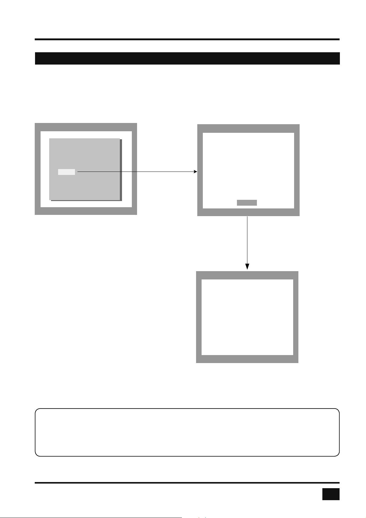
EDID (Display of Monitor Data)
Use arrow keys to navigate in the CONSOLE menu to the entry EDID and press ENTER/SELECT to open
the EDID window.
CONSOLE
VIDEO OUTPUT
KEYBOARD
TOUCHSCREEN
MULTI MONITOR
EDID
Use the EDID command to read and display
monitor data (manufacturer, monitor name,
serial number etc.) from the monitor’s
EDID memory.
If VIDEO OUTPUT is set to “auto”, V-Switch
quad uses the optimum output resolution
offered by the EDID.
CONSOLE / EDID
Manufacturer: NEC
Monitor name: NEC LCD1860N
Serial No.: 123456YB
Vertical
rate: 55 – 85 Hz
Horizontal
rate: 31 – 80 KHz
Pixel clock: 140 MHz
Details
EDID / EDID DETAILS
monitor timing descriptor:
3F 48
40 30 62 E0 32 40 40 C0
13 00 98 32 11 00 00 1E
video modes:
FF FF 80
8159 0101 0101 0101
0101 0101 0101 0101
EDID (Extended Display Identifi cation Data) is a VESA standard data format that contains basic
information about a monitor and its capabilities. This information is stored in the monitor by the
manufacturer and can be read by V-Switch quad or graphics card via a monitor cable’s Display
Data Channel (DCC) interface.
V-Switch quad - Installation and Operation Manual
49
Page 54
ON SCREEN DISPLAY
OSD - VIDEO - VIDEO INPUT
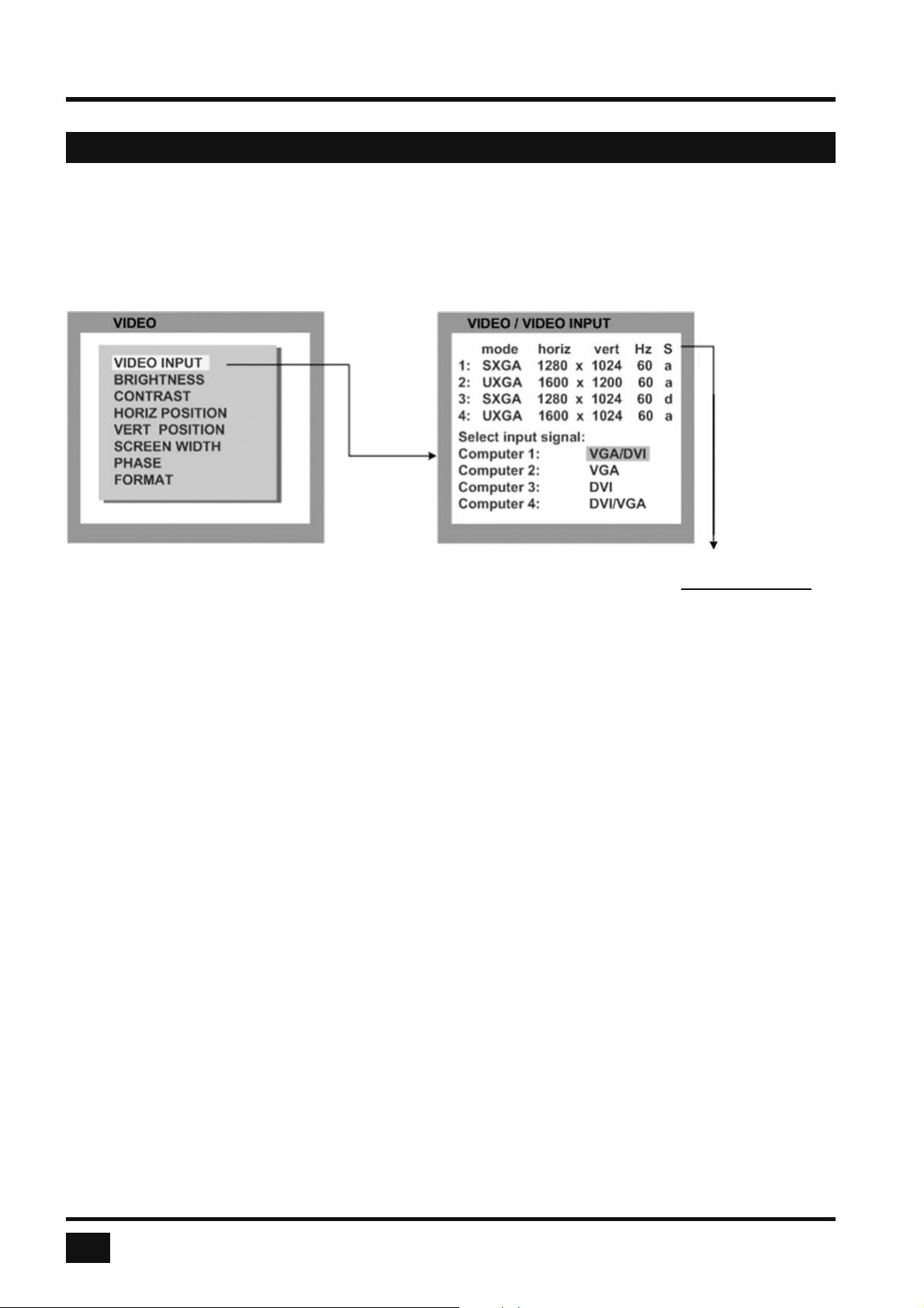
VIDEO INPUT (Display Video Formats)
Use arrow keys to navigate in the VIDEO menu to the entry VIDEO INPUT and press ENTER/SELECT to open
the VIDEO INPUT window.
S Signal
a = analog
The upper part of the VIDEO INPUT window shows the resolutions d = digital
at the four video inputs. g = sync on green
c = composite sync
Resolution recognition at the four video inputs is automatic.
Go to “Select input signal” and defi ne which video signal (VGA or DVI) is to be displayed.
If a setting with both signal inputs (VGA/DVI or DVI/VGA) is selected, the V-Switch quad will fi rst check
the fi rst input specifi ed. If there is no signal at this input, the second signal input will be checked.
On the next page is a list of video formats supported by V-Switch quad.
Some of the listed digital video modes accept reduced frame rates down to 22 Hz.
In rare cases, the V-Switch quad does not immediately recognize a change of the input video mode to UXGA
with reduced pixel rate. In this case, please retry.
With digital input and a resolution of 800x600, the input frame rate may be increased to up to 180 Hz.
This provides smooth video output even in Quad mode. To use this feature, it is necessary to choose this
resolution and refresh rate on all devices connected to the V-Switch quad’s video inputs.
50
V-Switch quad - Installation and Operation Manual
Page 55

ON SCREEN DISPLAY
OSD - VIDEO - VIDEO INPUT
VIDEO INPUT (Display Video Formats)
The table lists all video formats supported by V-Switch quad at the input ports.
Display Resolution Sync- Frame Rate
Mode (Pixel) Polarity analog digital
H x V H/V Hz Hz
CGA 640 x 350 +/- 85 85
CGA 640 x 400 -/+ 85 85
EGA 720 x 400 +/+ 70 70
EGA 720 x 400 -/+ 85 85
VGA 640 x 480 -/- 60 22 - 60
VGA 640 x 480 -/- 72 72
VGA 640 x 480 -/- 75 75
VGA 640 x 480 -/- 85 85
SVGA 800 x 600 +/+ 56 22 - 56
SVGA 800 x 600 +/+ 60 60
SVGA 800 x 600 +/+ 72 72
SVGA 800 x 600 +/+ 75 75
SVGA 800 x 600 +/+ 85 85 - 180
XGA 1024 x 768 -/- 60 22 - 60
XGA 1024 x 768 -/- 70 70
XGA 1024 x 768 +/+ 75 75
XGA 1024 x 768 +/+ 85 85
XGA/B 1152 x 864 +/+ 75 75
SUN 1152 x 900 +/+ 66 66
HDTVp 1280 x 720 +/+ --- 22 - 50
HDTVp 1280 x 720 +/+ --- 60
WXGA 1280 x 768 -/+ 60 60
UWXGA 1280 x 960 +/+ 60 60
UWXGA 1280 x 960 +/+ 85 85
SXGA 1280 x 1024 g 50 50
SXGA 1280 x 1024 +/+ 60 60
SXGA 1280 x 1024 g 72 72
SXGA 1280 x 1024 +/+ 75 75
SXGA 1280 x 1024 +/+ 85 85
WXGAp 1366 x 768 +/+ --- 22 - 60
SGI 1600 x 1024 +/+ 60 60
UXGA 1600 x 1200 +/+ 50 50
UXGA 1600 x 1200 +/+ 60 60
UXGAr 1600 x 1200 +/+ 50 50
UXGAr 1600 x 1200 +/+ 60 60
HDTVp 1920 x 1080 +/+ --- 22 - 24
HDTVp 1920 x 1080 +/+ --- 50
HDTVp 1920 x 1080 +/+ --- 60
WUXGA 1920 x 1200 +/+ --- 22 - 50
WUXGA 1920 x 1200 +/+ --- 60
V-Switch quad - Installation and Operation Manual
51
Page 56
ON SCREEN DISPLAY
OSD - VIDEO - BRIGHTNESS / CONTRAST / H + V POSITION
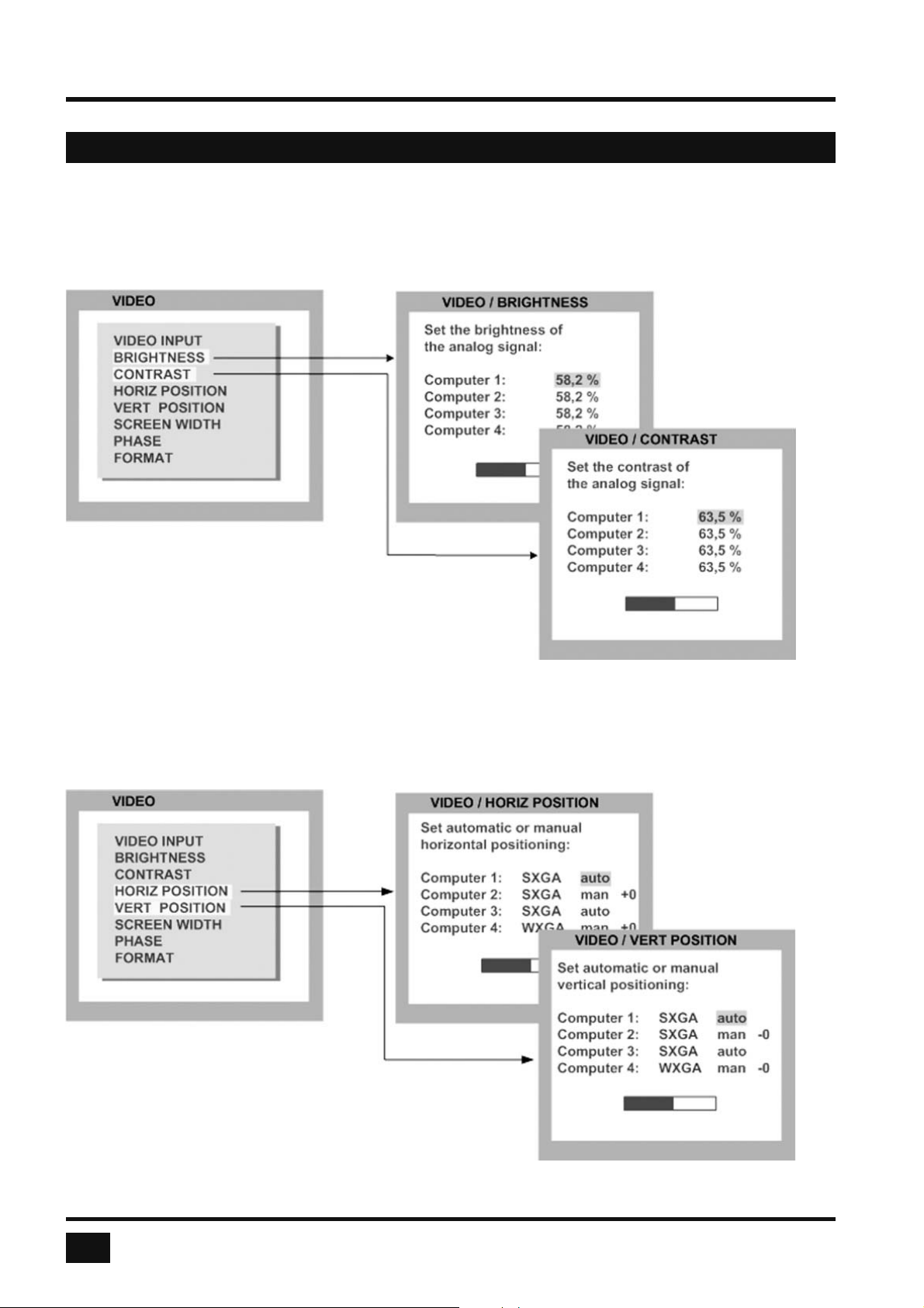
BRIGHTNESS – CONTRAST
Use arrow keys to navigate in the VIDEO menu to the entry BRIGHTNESS or CONTRAST and press ENTER/
SELECT to open the BRIGHTNESS or CONTRAST window.
Use this feature to adjust the brightness or contrast
of analog video input signals.
HORIZ / VERT POSITION (horizontal / vertical position of computer screen)
Use arrow keys to navigate in the VIDEO menu to the entry HORIZ POSITION or VERT POSITION and press
ENTER/SELECT to open the HORIZ POSITION or VERT POSITION window.
In case of incorrect horizontal position of a
computer screen, use this feature to adjust
the computer screen manually. Use the arrow
keys to navigate to the AUTO/MAN fi eld and set
MAN for manual. Use the “+” or “-” keys in the value
fi eld to adjust the vertical position between –40 and +40,
and the horizontal position between –20 and +20.
52
V-Switch quad - Installation and Operation Manual
Page 57
ON SCREEN DISPLAY
OSD - VIDEO - SCREEN WIDTH / PHASE
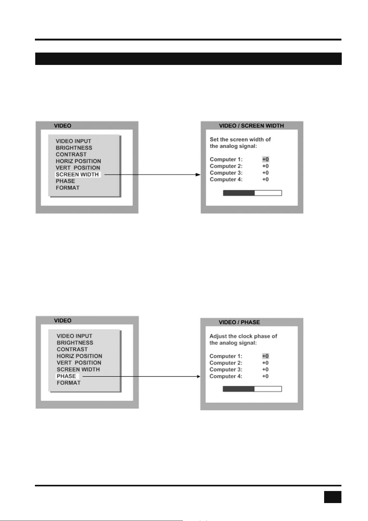
SCREEN WIDTH
Use arrow keys to navigate in the VIDEO menu to the entry SCREEN WIDTH and press ENTER/SELECT to
open the SCREEN WIDTH window.
Normally, screen width (number of horizontal pixels) is defi ned by the VESA standard. If the screen appears
blurred, change this setting to improve screen quality.
PHASE
Use arrow keys to navigate in VIDEO menu to the PHASE line and press ENTER/SELECT to open the
PHASE window.
Incorrect phase (sampling time of pixel color value) may result in blurring, bad contrast, or poor legibility. Use
this setting to adjust phase.
V-Switch quad - Installation and Operation Manual
53
Page 58
ON SCREEN DISPLAY
OSD - VIDEO - FORMAT
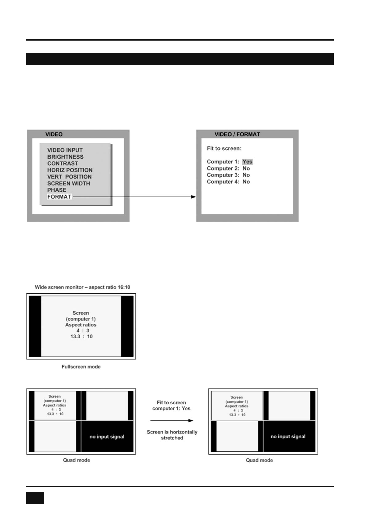
FORMAT
Use arrow keys to navigate in the VIDEO menu to the entry FORMAT and press ENTER/SELECT to open
the FORMAT window.
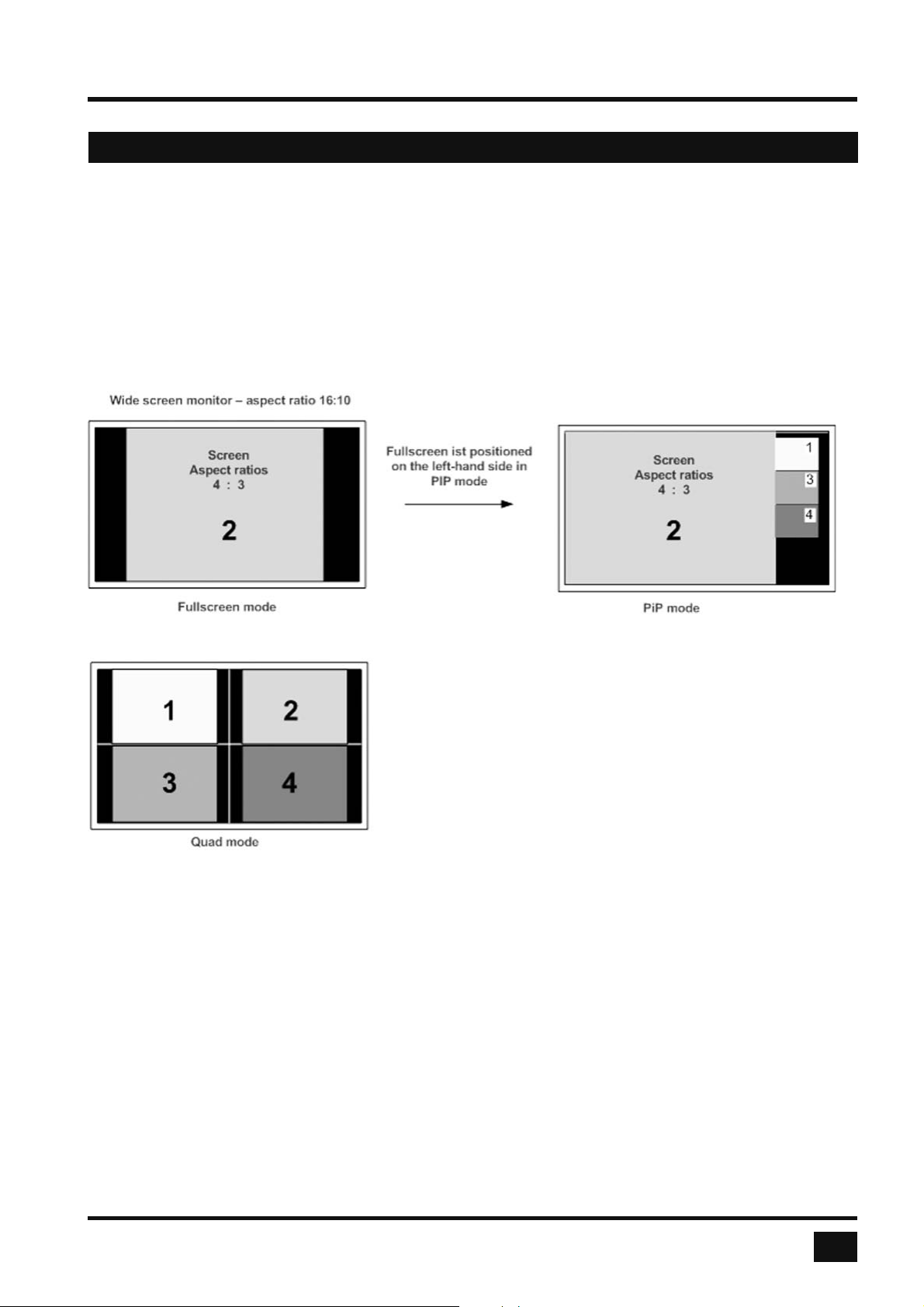
When using a wide-screen monitor (aspect ratio 16:10) in Quad-mode, a video input with a different aspect
ratio is normally displayed with black borders to the left and right. If fi t to screen is enabled, the image is
resized to fi ll the entire quadrant in Quad mode.
54
V-Switch quad - Installation and Operation Manual
Page 59
ON SCREEN DISPLAY
OSD - VIDEO - FORMAT
PiP mode for wide-screen monitors
If you use a wide-screen monitor (for example with an aspect ratio of 16:10), PiPs are placed to the right side
of the active channel, if that channel does not have a wide-screen aspect ratio. Provided appropriate PiP size
(20%) is set, PiP images are thus placed entirely outside the full screen channel.
V-Switch quad - Installation and Operation Manual
55
Page 60
ON SCREEN DISPLAY
OSD - COMPUTER - KEYBOARD / MOUSE
KEYBOARD
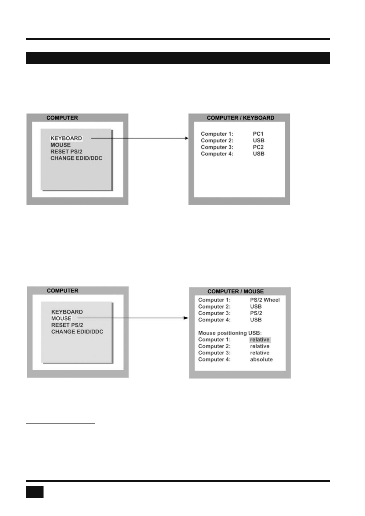
Use arrow keys to navigate in the COMPUTER menu to the entry KEYBOARD and press ENTER/SELECT
to open the KEYBOARD window.
Use this display feature to identify which keyboard type (USB, PC1, PC2 or PC3) has been recognized at
which computer port.
MOUSE
Use arrow keys to navigate in COMPUTER menu to the MOUSE line and press ENTER/SELECT to open the
MOUSE window.
The upper half of the MOUSE window shows which mouse type (USB, PS/2 or PS/2 wheel) has been
recognized at which computer port.
USB – mouse positioning
For USB ports, you may specify absolute or relative mouse positioning.
Choose absolute mouse positioning when a device is connected to the console that supports absolute
coordinates, such as graphic trays, screen pads or KVM extenders (HETEC V-IP).
56
V-Switch quad - Installation and Operation Manual
Page 61
ON SCREEN DISPLAY
OSD - COMPUTER - RESET PS/2 / CHANGE EDID/DDC
RESET PS/2
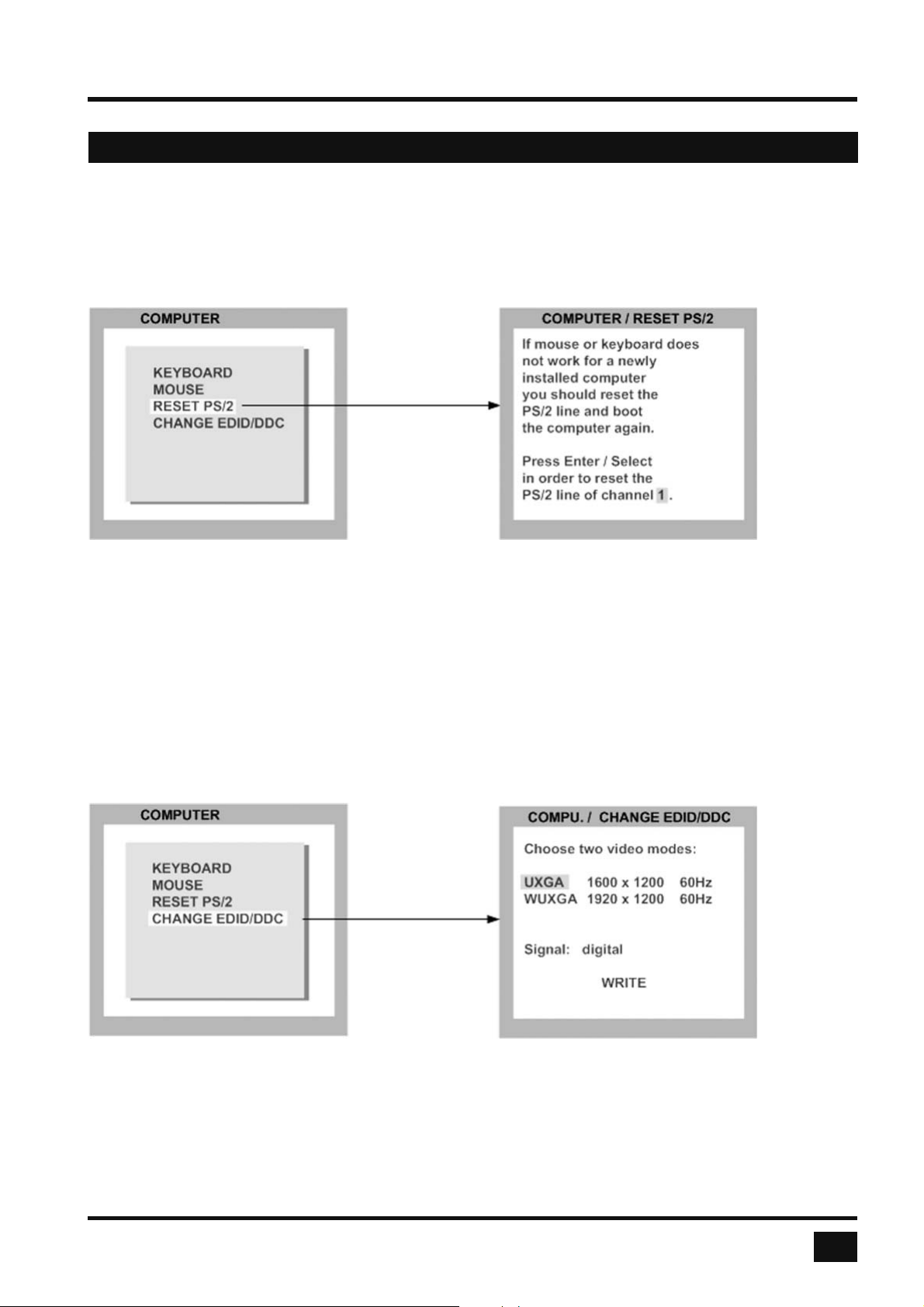
Use arrow keys to navigate in the COMPUTER menu to the entry RESET PS/2 and press ENTER/SELECT
to open the RESET PS/2 window.
Use arrow keys ◄► or “+” and “-” keys to select the channel (1 to 4) you wish to reset and confi rm by pressing
ENTER/SELECT.
CHANGE EDID/DDC
Use CHANGE EDID/DDC to add two freely selectable video modes to the list of video modes saved in the
EDID visible to the connected computers at the four video input ports.
Use arrow keys to navigate in the COMPUTER menu to the entry CHANGE EDID/DDC and press ENTER/
SELECT to open the CHANGE EDID/DDC window.
Use arrow keys ◄► to select the fi rst additional video mode.
Use arrow keys ▲▼ to navigate to and arrow keys ◄► to select the second video mode.
Use arrow keys ▲▼ to navigate to “Signal“ and arrow keys ◄► to switch between analog or digital. This
setting specifi es whether the EDID should identify the V-Switch quad as an analog or digital device. Usually it is
safe
to leave this setting at “digital”.
V-Switch quad - Installation and Operation Manual
57
Page 62
ON SCREEN DISPLAY
OSD - COMPUTER - CHANGE EDID/DDC
CHANGE EDID/DDC
Finally, use arrow keys ▲▼ to navigate to WRITE and press ENTER/SELECT to open the EDID / CHANGE
EDID/DDC window.
When the window shown on the right opens, connect the video output to the video input to be programmed
with a DVI video cable.
Since you have to disconnect the video output device for this purpose, programming must be executed “blindly”.
Programming is executed by pressing the ENTER/SELECT key twice.
Remove the cable connection and re-connect the
video output to the video output device.
In the window on the right, you can check whether
programming was completed successfully.
Program EDID:
successful / failed
If “successful” is displayed, the selected video
input has been successfully programmed.
Where appropriate, repeat the above process for the
three other video inputs of your V-Switch quad.
Alternatively, you may also execute EDID programming using the CONFDEV confi guration program.
As CONFDEV runs on an external Windows computer connected to the V-Switch quad, EDID programming
can be monitored on the screen of the Windows computer.
The CONFDEV confi guration program is described on page 64.
58
V-Switch quad - Installation and Operation Manual
Page 63
ON SCREEN DISPLAY
OSD - HELP - COMMAND / ABOUT
COMMAND
Use arrow keys to navigate in the HELP menu to the entry COMMAND and press ENTER/SELECT
to open the COMMAND window.
HELP
COMMAND
ABOUT
CONTACT
HELP / COMMAND
Hotkey plus :
Q quad mode
F full screen mode
P PiP/select channel
I PiP menu
O On Screen Display
V safe output mode
1-4 full screen mode:
select channel 1-4
F1–F4 quad mode:
select channel 1-4
The HELP / COMMAND LIST window lists keyboard commands and their functions.
ABOUT
Use arrow keys to navigate in the HELP menu to the entry ABOUT and press ENTER/SELECT
to open the ABOUT window.
HELP
COMMAND
ABOUT
CONTACT
HELP / ABOUT
V-Switch quad
HETEC Datensysteme GmbH
The HELP / ABOUT window shows the
current versions of the V-Switch quad.
The ABOUT / DETAILS window shows
the confi guration of the V-Switch quad
fi rmware and hardware.
V-Switch quad - Installation and Operation Manual
Revision : 1.40 / 5336
Details
Configuration
ABOUT / DETAILS
V-Switch quad
HETEC Datensysteme GmbH
Boot count: 1
Revision: 1.40 / 5336
Build: 25.03.2008
Video 906: 1.320 / 1.08
Console: 1.07 / 1.08
CPLD: 55
59
Page 64
ON SCREEN DISPLAY
OSD - HELP - ABOUT / CONTACT
ABOUT (continued)
HELP
COMMAND
ABOUT
CONTACT
The ABOUT / CONFIGURATION
window shows the confi guration of the
V-Switch quad fi rmware (see page 67
for a description of CONFIGURATIONS).
HELP / ABOUT
V-Switch quad
HETEC Datensysteme GmbH
Revision : 1.40 / 5336
Details
Configuration
ABOUT / CONFIGURATION
Configuration:
TOUCHSCREEN
OSD languages:
EN
DE
ES
CONTACT
Use arrow keys to navigate in the HELP menu to the entry CONTACT and press ENTER/SELECT
to open the CONTACT window.
HELP HELP / CONTACT
HETEC Datensysteme GmbH
COMMAND
ABOUT
CONTACT
Landsberger Strasse 65
D- 82110 Germering
Germany
Phone : +49-89-894367-0
Fax: +49-89-894367-99
www.hetec.de
Thank you for using
V-Switch quad
The HELP / CONTACT window contains information on how to contact HETEC support.
For contact info see also page 61.
60
V-Switch quad - Installation and Operation Manual
Page 65

SERVICE
SERVICE INFORMATION
Maintenance and Repair
V-Switch quad does not contain any user-serviceable parts. Please report any malfunction or deviation from the
functionality described in this manual during operation to HETEC’s Technical Support Department.
If we cannot solve your problem by phone and fi nd that the fault is due to the unit, we will repair your unit free
of charge during our warranty period. Please pack the device carefully, if possible in its original packaging, and
send it to:
HETEC Datensysteme GmbH
Landsberger Straße 65
D-82110 Germering
Germany
Technical Support
If you cannot identify the cause of a problem, please contact HETEC, Technical Support.
To contact our technical support staff, please call:
Telephone +49 (0)89 - 89 43 67 - 0
Mondays through Fridays 08:30 AM to 12:30 PM (CET)
01:00 PM to 05:00 PM (CET)
V-Switch quad - Installation and Operation Manual
61
Page 66
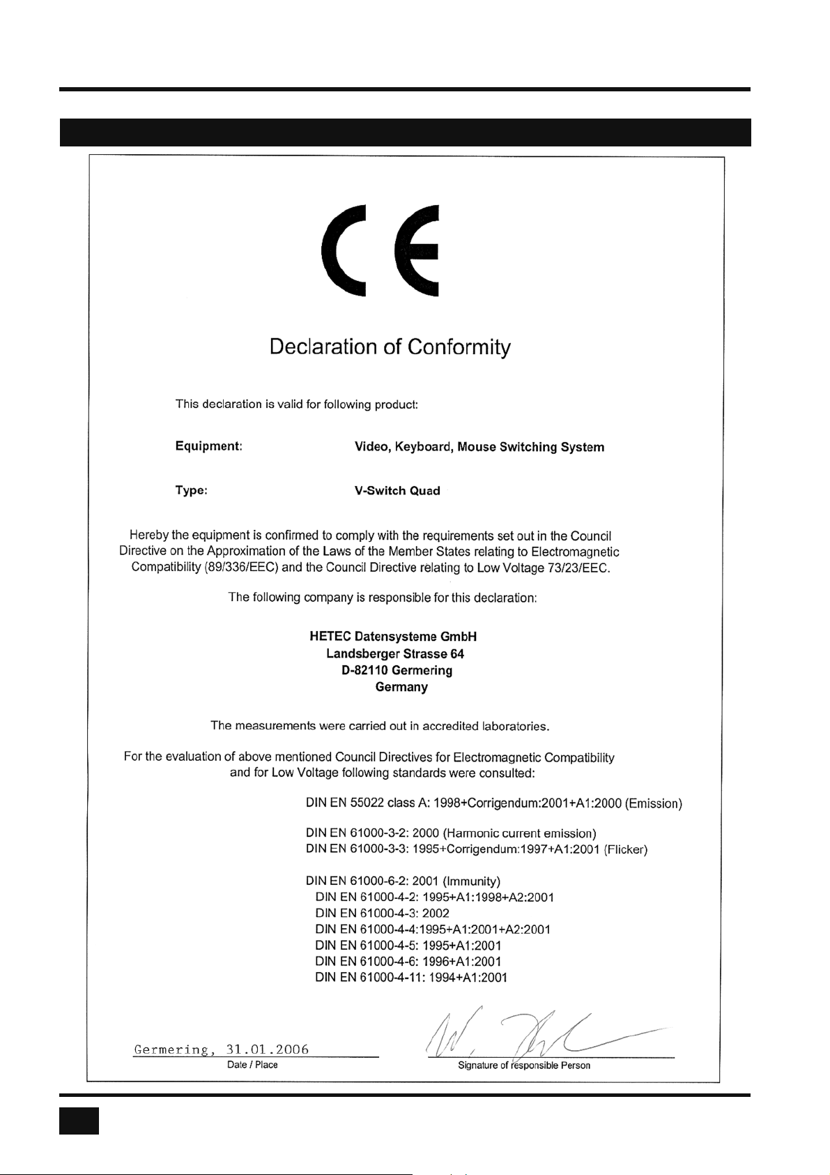
ANNEX
DECLARATION OF CONFORMITY
62
V-Switch quad - Installation and Operation Manual
Page 67
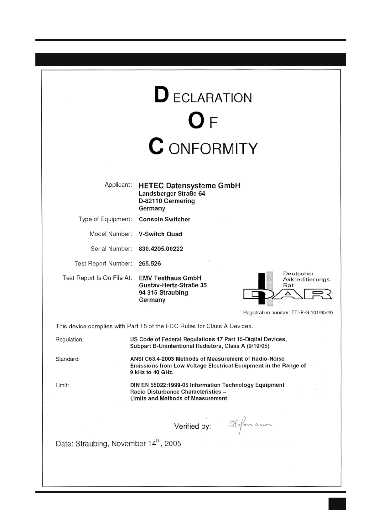
FCC DECLARATION
ANNEX
V-Switch quad - Installation and Operation Manual
63
Page 68
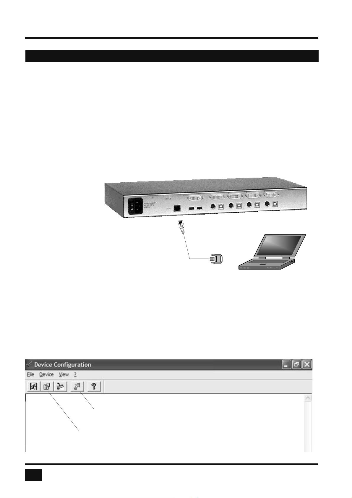
ANNEX
DEVICE CONFIGURATION PROGRAM
INSTALLATION OF DEVICE CONFIGURATION PROGRAM (CONFDEV)
To install the device confi guration software CONFDEV, you need
● A Windows computer with a free RS 232 COM-port
● Your V-Switch quad
● The installation CD containing the confdevEn.exe program
● The enclosed serial cable
Rear panel
Serial
Cable
Use the serial cable to connect the COM port of the Windows computer with the serial port of your
V-Switch quad.
Insert the installation CD into the CD-ROM drive and start the confdevEn.exe program.
The DEVICE CONFIGURATION PROGRAM (CONFDEV) window opens:
COM Port
64
Device
Configuration
Settings
V-Switch quad - Installation and Operation Manual
Page 69
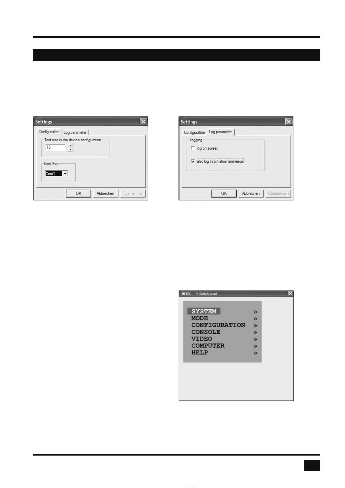
ANNEX
DEVICE CONFIGURATION PROGRAM
SETTINGS
The SETTINGS window allows you to set the font size for the OSD window, log parameters, and the COM port
to which the V-Switch quad is connected.
START DEVICE CONFIGURATION PROGRAM
Start confi guration by clicking on the green arrow in the device confi guration program.
When the window on the right is displayed,
you are in the main OSD menu.
NAVIGATION
Use arrow keys as in the OSD menu to navigate
to the desired line and confi rm by pressing ENTER.
Use the ESC key to return to the previous menu.
V-Switch quad - Installation and Operation Manual
65
Page 70
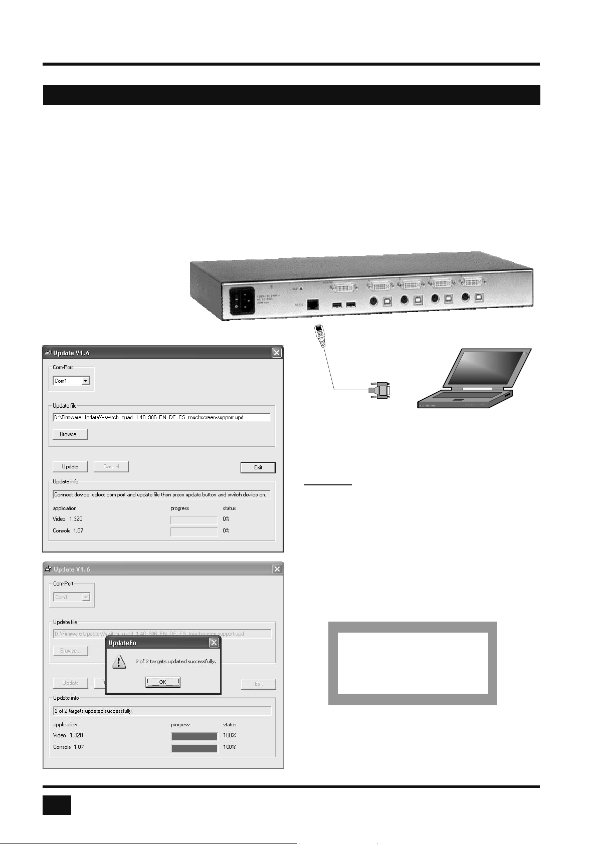
ANNEX
FIRMWARE UPDATE
To execute a fi rmware update, you need:
• a computer with serial port
• the update program (updateEn.exe), which you will fi nd on the enclosed CD
• the enclosed serial cable (RJ45 – DB9)
• the current fi rmware fi le, e.g. Vswitch_quad_1.40_906_EN_DE_ES_touchscreen-support.upd
Use the serial cable to connect the COM port of your computer to the RS232 port on the V-Switch quad.
Rear panel
Serial
Cable
Start the update program (updateEn.exe)
Set the desired COM port.
Enter drive and path of current fi rmware fi le under
Update fi le.
You can use the browse function (“Browse...“ - Icon)
to do so.
Click the “Update” button to start the upgrade
process.
The fi ve LEDs on the left side of the front panel
fl ash (green – yellow) during the upgrade.
Additionally, the upgrade process is indicated by
an OSD window.
HETEC V-Switch quad
Software upgrade running.
COM Port
66
Please wait.
After a successful update, V-Switch quad restarts
without changing confi guration.
V-Switch quad - Installation and Operation Manual
Page 71
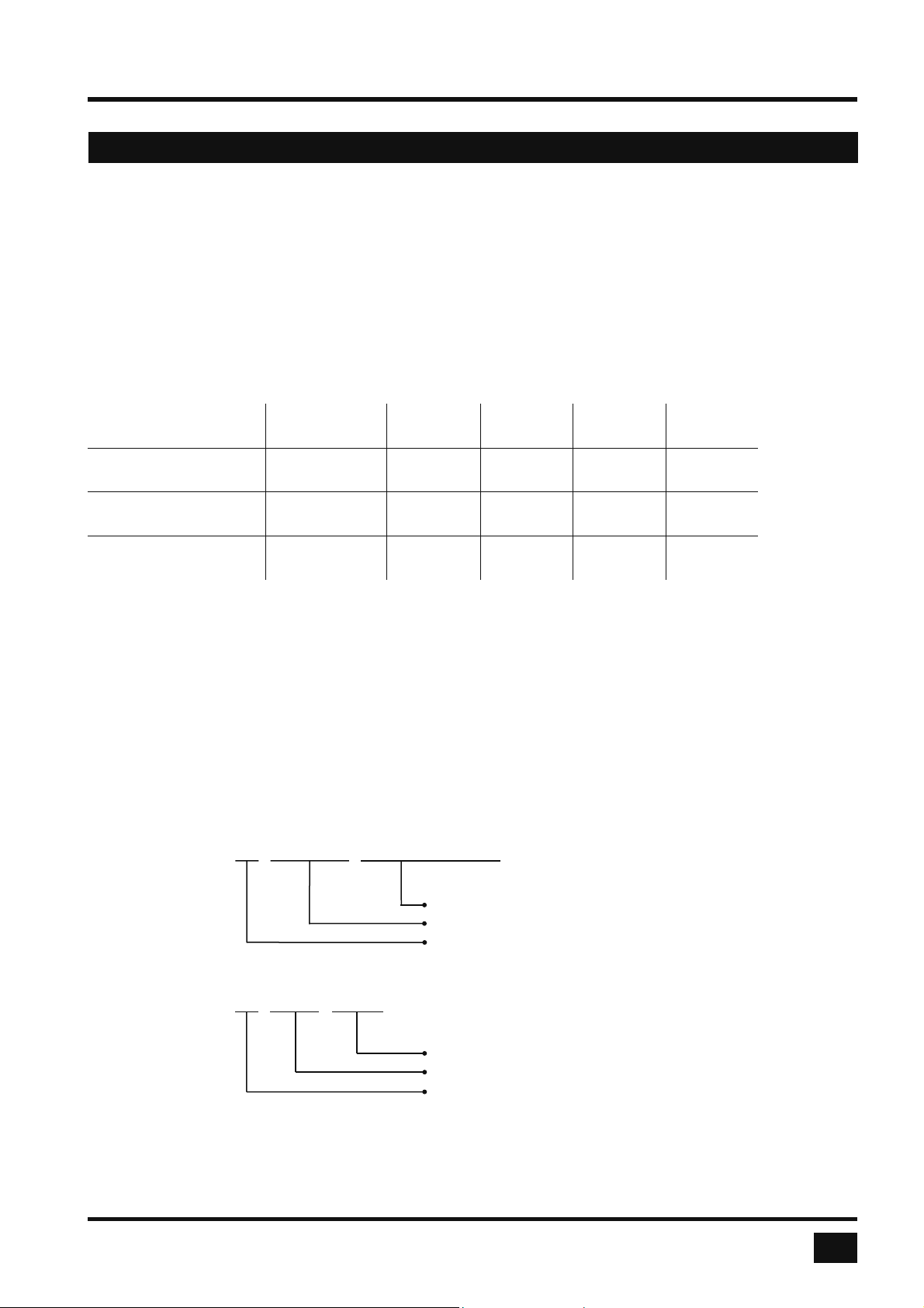
CONFIGURATIONS
V-Switch quad is available in three confi gurations:
- with touchscreen support
- with DCP-XML with English and German as OSD languages
- with DCP-XML with English and Spanish as OSD languages
ANNEX
Touchscreen
support
Touchscreen
DCP-XML EN+DE X
DCP-XML EN+ES X
Update fi les for all confi gurations are included with the V-Switch quad, and are also freely available from the
web address www.hetec.de/service/. The different confi gurations can be selected by the user by using a
specifi c update fi le. It is also possible to change the selected confi guration later by loading a different
update fi le on the V-Switch quad.
When choosing an update fi le, the confi guration of that fi le can be determined from the fi le name.
Examples:
VSwitch_quad_1.40_905_EN_DE_ES_touchscreen-support.upd
9
DCP-XML English
OSD
X
999
German
OSD
999
99
X
Spanish
OSD
X
9
Touchscreen support
English, German and Spanish OSD
Video processor 905
VSwitch_quad_1.40_906_EN_DE_dcp-xml.upd
DCP-XML support
English and German OSD
Video processor 906
V-Switch quad - Installation and Operation Manual
67
Page 72
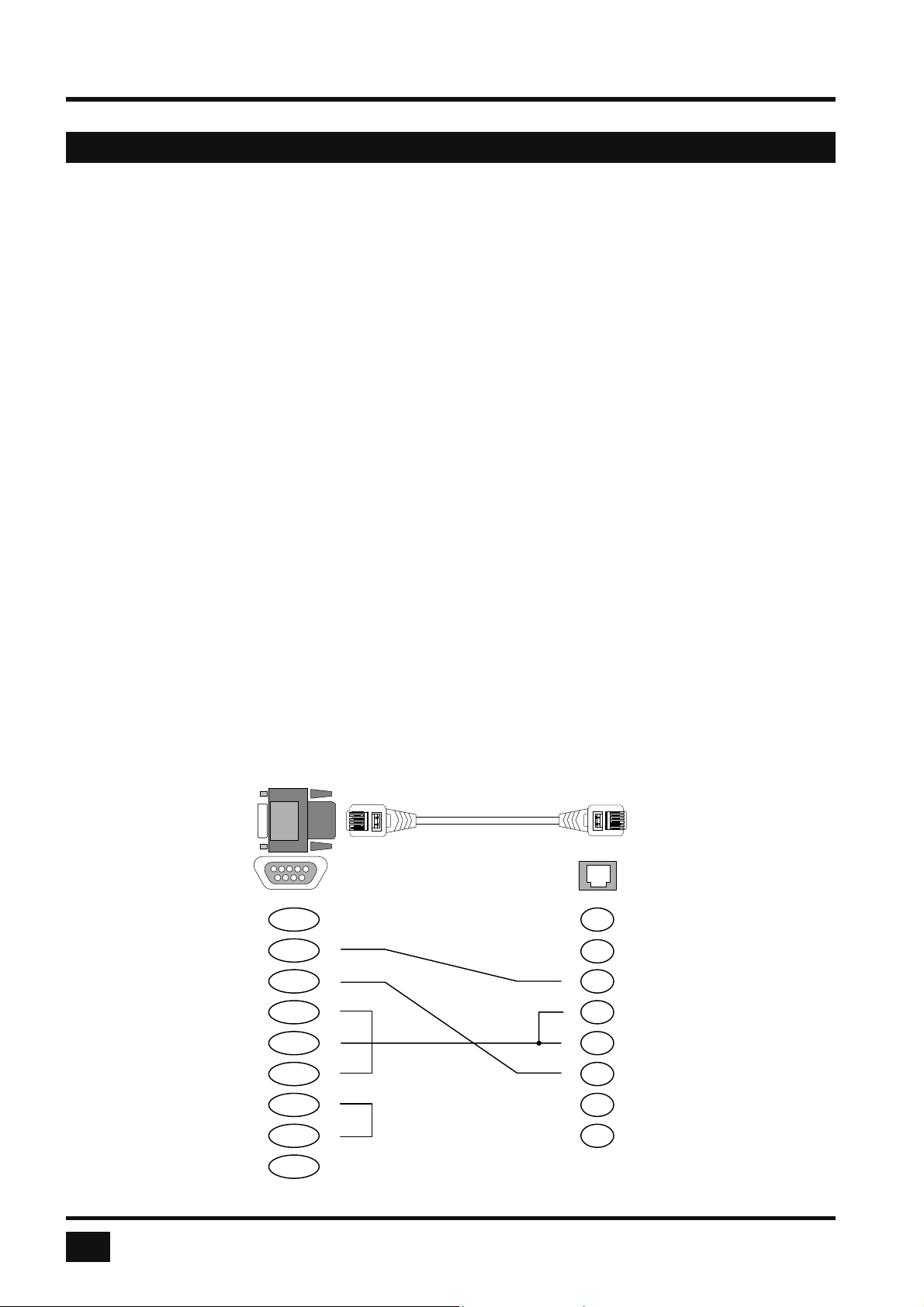
ANNEX
DELIVERABLES
Please use the list below to verify that all parts have been delivered.
The following components are included:
● 1 V-Switch quad (black or gray)
● 1 19” rack mount kit (black or gray)
● 1 Installation and Operation Manual
● 1 Installation CD
● 1 power cable
● 1 cable set HW-KON-DVI-VGA: 1 video cable DVI/DVI for console
1 short PS/2 keyboard mouse/USB adaptor
● 2 cable set HW-CPU-VGA: 1 video cable DVI/VGA, length 2.0 m
1 Y-cable PS/2 for mouse and keyboard, length 2.0 m
1 USB cable plug A - plug B, length 2.0 m
● 2 cable set HW-CPU-DVI: 1 video cable DVI/DVI, length 2.0 m
1 Y-cable PS/2 for mouse and keyboard, length 2.0 m
1 USB cable plug A - plug B, length 2.0 m
● 1 serial adaptor with green CAT5 cable (description below)
SERIAL ADAPTER
DB 9 – RJ45 FEMALE
DCD
RXD
TXD
DTR
GRD
DSR
RTS
CTS
1
2
3
4
5
6
7
8
black
yellow
red
RJ 45 CABLE
MALE
n.c.
n.c.
n.c.
n.c.
1
2
3
blue
orange
black
4
red
5
6
green
7
8
yellow
brown
68
RI
9
white
V-Switch quad - Installation and Operation Manual
 Loading...