

Page 1
PLEASE RETAIN THIS GUIDE FOR FUTURE REFERENCE
Operating & Installation Manual
BK132
Rev 03
August 2011
Part No. AFS1574
Multifuel Stoves
AX
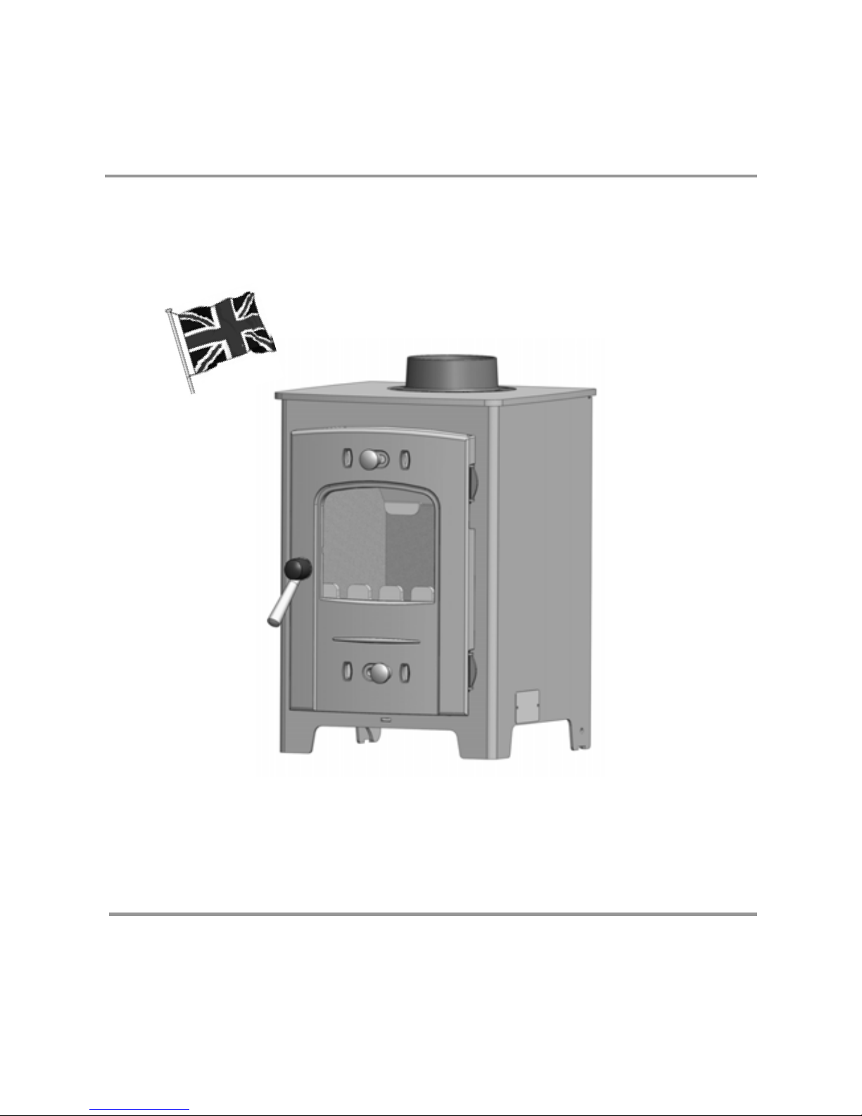
The AX Multifuel Stove Range
British Made
AX1M - S2
AX2M - S2
Page 2

Contents
Page No.
INTRODUCTION
Warning Notice 3
Safety Notices 4
INSTALLATION
Fitting The Flue Outlet & Hotplate 4
Technical data 5
Fitting the grate 6
Firebox Liner Panels 7
Final Check 8
OPERATION
Air wash control 9
Primary air control 9
Multipurpose operating tool / Ash pan 10
MAINTENANCE
Cleaning the stove 11
Summer Storage 12
Adjusting the Door Hinges 12
Fuel retainer 12
AX1 Spare Parts Diagram 13
AX2 Spare Parts Diagram 14
GUARANTEE 15
FINAL FACTORY CHECK 16
2
Page 3

WARNING
IT IS A LEGAL REQUIREMENT THAT THE INSTALLATION OF ALL
NEW OR REPLACEMENT, WOOD OR SOLIDFUEL HEATING
APPLIANCES ARE REQUIRED TO OBTAIN BUILDING CONTROL
APPROVAL FROM YOUR LOCAL AUTHORITY OR THE
INSTALLATION WORK MUST BE CARRIED OUT THROUGH A
GOVERNMENT APPROVED COMPETENT PERSONS SCHEME
SUCH AS OPERATED BY HETAS.
IF IN DOUBT, CONTACT HETAS LIMITED
TELEPHONE NUMBER : 0845 634 5626
www.hetas.co.uk
THIS STOVE MUST NOT BE CONNECTED
TO A SHARED FLUE SYSTEM
TO ALL USERS
PETROLEUM COKE
SOME OF WHOSE BRAND NAMES ARE
‘CALCO’, ‘PETROCOKE’ AND ‘WONDERCO’
MUST NOT BE BURNED IN THIS APPLIANCE
BITUMINOUS HOUSE COAL
SHOULD NEVER BE USED IN YOUR STOVE
TO USE THESE FUELS WILL INVALIDATE
THE APPLIANCE GUARANTEE.
IF IN DOUBT CONTACT THE SOLID FUEL ASSOCIATION
TELEPHONE NUMBER 0845 601 4406
www.solidfuel.co.uk
3
Page 4
SAFETY
A fireguard conforming to BS 8423:2002
should be used in the presence of children
and old or infirm people.
Please note, this appliance should be used
with the fire door closed at all times except
when re-fuelling or de-ashing.
Do not use aerosol sprays or any other
flammable materials near the appliance
under fire.
Do not fit an extractor fan in the same
room as the appliance.
Fire cement is caustic, hand and eye
protection should always be worn,
prolonged contact with the skin should be
avoided.
The manufacturer will not be responsible
for any consequential or incidental loss or
injury however caused.
Before continuing any further, with the
installation of this appliance please read the
following guide to manual handling.
x Always obtain assistance when lifting the
appliance
x When lifting always keep your back straight,
bend your legs not your back
x Avoid twisting at the waist. It is better to
reposition your feet.
x Avoid upper body/top heavy bending. Do
not lean forwards or sideways when
handling the fire
x Always grip with the palms of your hands
do not use your fingertips for support
x Always keep the stove as close to the body
as possible as this will minimise the
cantilever action.
x Use gloves to provide additional grip.
INTRODUCTION
4
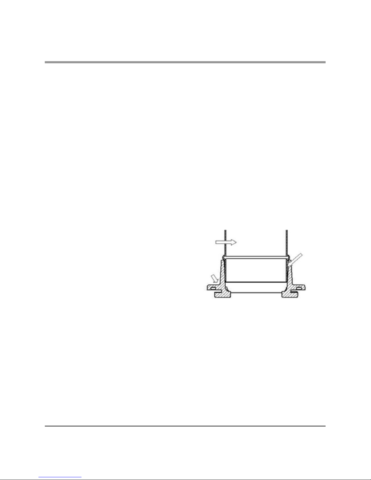
FITTING THE FLUE OUTLET AND
HOT PLATE
The flue outlet spigot is found packed inside the
appliance . The hot plate (blanking plate) is
supplied fitted to the top opening and is removed
by turning anti-clockwise (as is the flue outlet).
Smear a very thin layer of fire cement on the
mating faces of the flue outlet and the hot plate.
Fit the outlet to the appliance in the desired
position.
Lock into place by rotating clockwise and tighten
by tapping with a block of wood and mallet from
inside of the appliance. Similarly, fit the hot plate
(blanking plate) to the unused opening. Clean off
any surplus fire cement.
Place appliance on the hearth and make sure that
it is level and does not rock.
Connect the chimney ensuring all joints are sealed
with fire cement.
Note : The flue pipe must be fitted inside the outlet
spigot. Failure to do so could result in the spillage
of condensation running down the flue.
Fig. 1. Flue & Spigot Fitting
Inside
Flue
Pipe
Outer
Spigot
Page 5
5
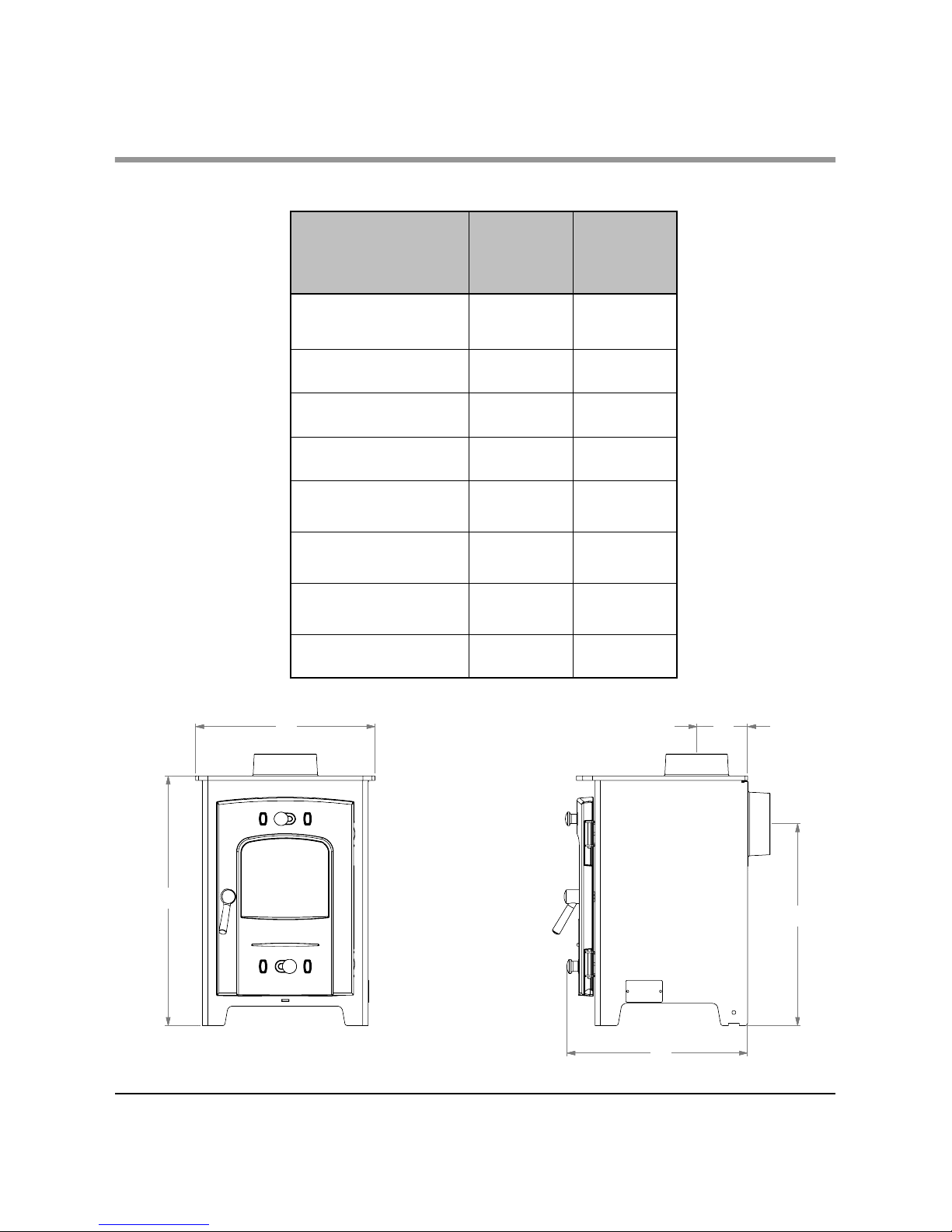
TECHNICAL DATA
TECHNICAL DATA
AX1
Multifuel
AX2
Multifuel
Room Heater
Only Output (kW)
1 - 41 - 5
Height (mm) ‘A’ 458 475
Width (mm) ‘B’ 330 370
Depth (mm) ‘C’ 323 333
Height to Centre
of Rear Flue (mm) ‘D’
370 387
Depth from Back to
Centre of Flue (mm) ‘E’
93.5 93.5
Flue Diameter
( mm / Inches)
102 (4") 102 (4")
Weight Packed (Kg) 39.5 41.5
A
B
C
D
E
Page 6
FITTING THE GRATE
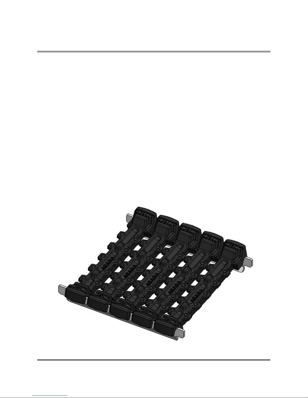
Note : The grate bars are factory assembled,
however during transit, they may have been
dislodged. Please see the instructions below on
grate assembly.
Grate
The grates in the AX1 / 2 stoves, comprise of a
series of 5 cast iron grate bars, seated on a pair of
combs. All bars in the grate are identical, the bar is
fitted with the ends of the bars marked ‘H’ sitting on
the front comb, and the ends marked ‘L’ sitting on
the rear grate bar comb.
See image below.
INSTALLATION
6
Page 7
7
INSTALLATION
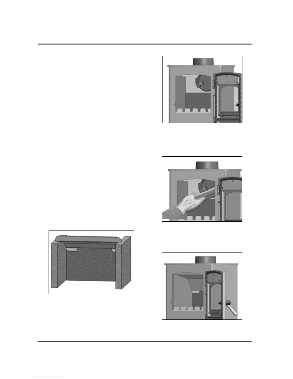
FIREBOX LINER PANELS
The AX range of stoves use firebox
liner panels to the sides and back. The throat plate
sits on top of the sides and rear panels. These
should come fitted to your stove, if however they
are not, proceed as follows to fit them.
x Open the fire door.
x Remove the fuel retainer by lifting free of the
out from the front brace
x Set the smaller liner into the back of the
firebox.
x Insert side liner panels. (See Fig. 2)
x Fit the throat plate with the projecting lugs
sitting on top of the side liners. The long
centre tab on the back edge rests on the
rear liner. The shorter turn down tabs
against the vertical face. (See Fig. 3 & 4)
x Replace the front fuel retainer.
Note: Neither the rear firebox liners nor the
side firebox liners are ‘handed’, both faces are
suitable for direct contact with the fire bed.
Note : Cracking of the lining panels does not
effect efficiency.
Fig. 5. Overall View Of Liners
& Throat Plate Assembly
Fig. 2. Liners Inserted
Fig. 3. Inserting The Throat Plate
Fig. 4. Liners & Throat Plate
Correctly Fitted
Page 8

8
INSTALLATION
Before handing over the installation to the
customer it is a requirement under Document J the appliance is
lit and the functioning of the chimney system is checked for
satisfactory operation.
x Be sure that the chimney is operating and ALL smoke and
fumes are vented to the atmosphere through the chimney
terminal.
x Check all joints and seals.
x Clean the outside of the appliance to
prevent any stains becoming burnt on.
x Check the flue draught which should read 1 - 2mmH20, or
0.1 - 0.2 mbar.
x Explain the controls and operation of the appliance to the
customer.
x Ensure all aspects of the installation of the stove conform to
current building regulations and the installation is reported
to your local building control department.
FINAL CHECK
Note - All local regulation , including those referring to National and European standards need to be
complied with, when installing the appliance. We strongly advise that installation should only be carried
out by a qualified Solid Fuel Heating Engineer, covered by the HETAS scheme , as installation by
non-qualified persons may affect the stove operational safety and the product guarantee.
The building Regulations for England and Wales 2000 ref Approved Document J 2010 edition (issued by the
DTLR). The Building Standard (Scotland) (Consolidation) Regulations. Detailed recommendations for
installation of Appliances, chimneys and flues are outlined in the current issue of the following British Standards
BS6461, BS8303 and BS4543
Full details of UK installation regulations can be obtained from the following web site: -
www.planningportal.gov.uk/uploads/br/BR_PDF_ADJ_2010.pdf
Page 9
9
OPERATING INSTRUCTIONS
AIR INLET CONTROLS
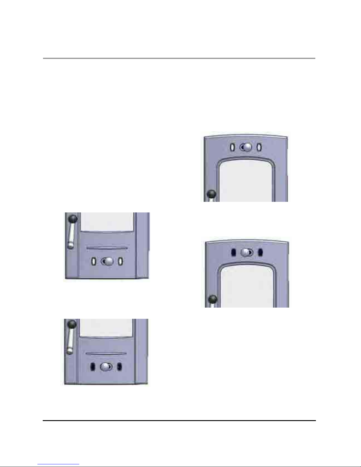
The AX range of stoves have two air inlet
controls.
The primary air inlet providing under draught to the
base of the fire chamber through the control slider
located under the window of the fire door.
The air wash system, so called because its preheated high speed air, washes across the inner
face of the door glass, keeping it clear. This also
provides an over draught to the fuel bed.
PRIMARY AIR
Air enters the appliance through the control on the
bottom of the fire door. The AX 1 & 2 has a single
control knob which slides left to right. Sliding the
knob to the Right, see Fig.6, will increase the
amount of air intake to the stove. To Decrease,
push the slider to the Left as in Fig. 7
AIR WASH SYSTEM
The air wash has an internal sliding plate with
slots, housed in a cover plate, and is located inside
the fire door. Sliding the control knob to the Right
as far as it will go, achieves the fully open position,
see Fig. 8. Sliding it to the Left will shut off the air
inlet slots as shown in Fig. 9.
Fig. 7. Fully Closed Position
Fig. 6. Fully Open Position
Fig. 8. Air Wash Fully Open Position
Fig. 9. Air Wash Fully Closed Position
Please note:
When adjusting the air controls remember they
may be hot, always use a heat resistant glove
Page 10
MULTI PURPOSE OPERATING
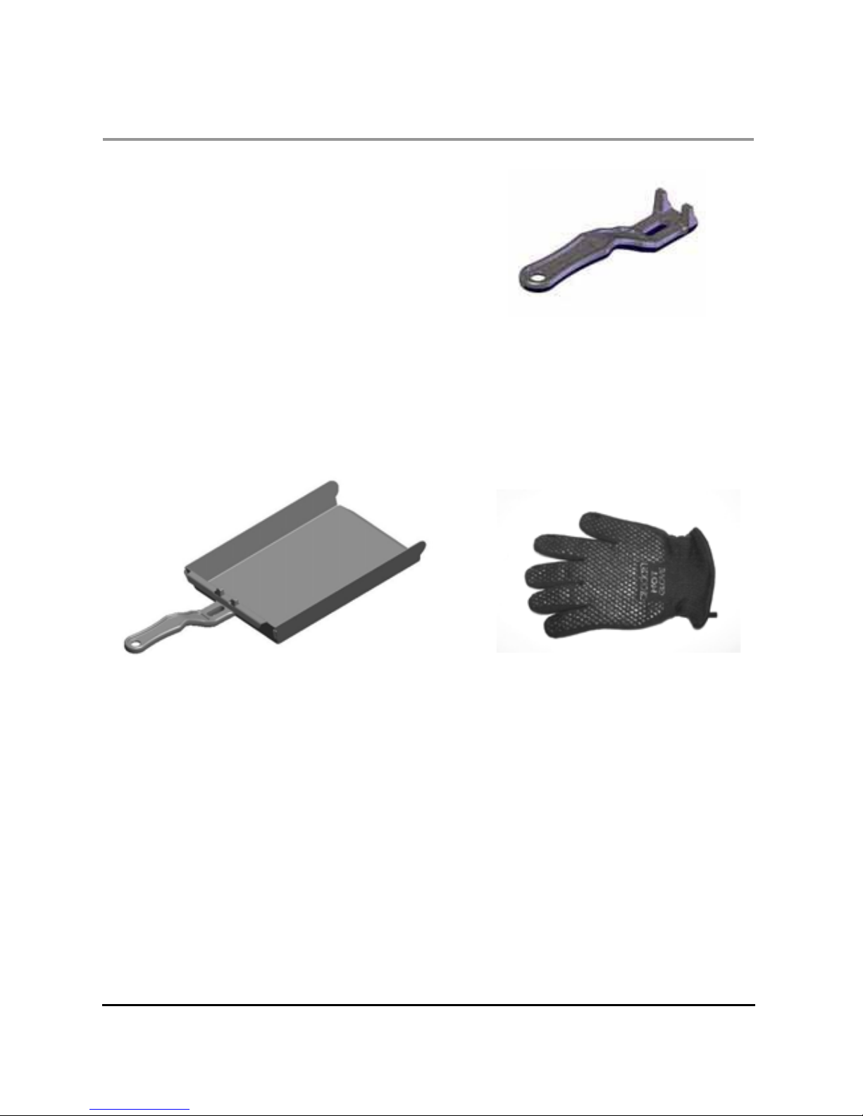
TOOL
Your AX stove is supplied with a multi purpose
operating tool, used for adjusting the air inlet control
and the removal of the ash pan. (See Fig 10/10a)
TO EMPTY THE ASH PAN
The AX range of stoves are supplied with a unique
ash pan. To empty or remove the ash pan, open the
fire door, fit the fork end of the operating tool into
the ash pan slots and remove from the ash pit
chamber.
Empty the ash into a suitable container and
replace the ash pan into the stove, withdraw the
operating tool and close the fire door.
Fig. 10a. Operating Tool & Ash pan
10
OPERATING INSTRUCTIONS
Please Note:
A stove mitten is supplied with your AX stove, ( Fig. 10b) this is provided for the operation of the fire door
handle and air controls whilst the stove is in use. Care must be taken when opening and closing the fire
door as any surrounding areas of the stove will be very hot.
WARNING :
Never attempt to open the fire door whilst the appliance is in use WITHOUT the use of the stove mitten
or suitable gloves, serious injuries may occur.
Caution must be taken when re-fuelling the
appliance, always keep the stove mitten away from naked flames and sparks.
Always use the stove mitten when emptying the ash pan.
Fig.10 Operating Tool
Fig.10b Stove Mitten
Page 11

ANNUAL MAINTENANCE
It is important that your appliance is regularly
serviced in accordance with these instructions.
This should be carried out at least annually by a
qualified person and should consist of the
following :
CLEANING
Important; Under some circumstances soot can
quickly build up on the throat plate and adjacent
areas. The throat plate should be removed and
checked monthly, and any debris stripped off. Similarly, clean the upper surface of the firebox.
Remove the firebrick linings and throat plate,
inspect all gasketing on doors, glass etc, and
re-order any items that may need replacing from
your AX stove Dealer.
With a wire brush clean inside the appliance
paying particular attention to the small inlet holes
of the air inlets on the inside of the fire door.
Sweep the chimney and confirm that it is sound.
Examine all joints in the flue pipe etc, and re-seal
if necessary. Re-assemble and leave with the air
inlet and air wash control about half way open.
This will allow a free flow of air through the
appliance thus preventing moisture and
condensation from building up inside the stove and
chimney.
CHIMNEY SWEEPING
Sweeping should be carried out with an
appropriate sized bristle brush and rods to suit
chimney size and type. As with all appliances
regular sweeping of the flue is essential to avoid
danger of blockage and the escape of poisonous
fumes. Access for cleaning should also be
incorporated in the chimney (e.g.. Soot door or
access through the register plate).
Any existing chimney should be swept prior to
installation of the appliance, and swept again a
second time within one month of regular use after
installation to establish frequency of sweeping
required. This should be done by a competent
person such as a NACS chimney engineer who will
provide a Certificate Of Chimney Sweeping.
The whole flue way including the outlet must be
swept at least twice per burning season. It is
important that the flue ways, flue pipe and chimney
be cleaned prior to lighting the appliance after a
prolonged shut down period.
DOOR GLASS
The door glass should remain clear during normal
burning. However, under certain conditions, such
as burning at a low rate or damp wood, or overnight burning, the glass may become somewhat
blackened. To remedy this, operate the appliance
at a fast rate. Alternatively when the stove is cold,
open the door and clean the inside face of the
glass with a damp cloth or with glass cleaner
(available from fire stockists). A piece of cloth
moistened with vinegar and dipped in wood ash
(not coal ash) will provide a good soft scourer to
remove the soot without scratching the glass.
OUTER FINISH
The outer finish of the appliance is a durable high
temperature paint. It is best cleaned by brushing
down with a clean shoe brush. Do not allow
moisture to remain on the appliance whilst cold or
surface rust may form.
The high temperature paint should not require
attention for some time, depending on use. The
hotter the fire burns sooner repainting will be
necessary. Aerosol tins of paint are available for
complete refurbishing.
Before repainting make sure that the fire is out and
the stove is cold.
x Remove the door glass
x Lightly wire brush, or rub with wire wool, the
body of the appliance to remove any loose
paint or rust.
x Mask or remove items such as brass work.
x Any adjacent brickwork, mantelpiece, hearth
etc, should be carefully masked for quite a
distance around the appliance. This
precaution is to prevent discolouration of the
surrounding brickwork or wall paper etc.
Re-spray in a well ventilated area, avoid
breathing the vapour. Refer to safety
instructions on paint cans.
x When the paint is dry refit the door glass &
any other parts previously removed.
x Leave the appliance for eight hours before
lighting a fire.
x Burn slowly for the first four hours, then build
up heat slowly to gradually cure paint.
Note: Use genuine Arada touch up spray as some
paints interact. This could ruin the finish and
invalidate the guarantee.
SERVICE & MAINTENANCE
11
Page 12
12
SERVICE & MAINTENANCE
SUMMER STORAGE / NON
USAGE
Please ensure that your stove is left clean and
moving components are well lubricated for the
summer months (during periods of prolonged non
use). If possible store the throat plate outside of the
stove, check all moveable components, at regular
intervals, to ensure they are moving freely.
Allow air movement through the stove, by opening
the air wash and primary air inlet(s) controls to
about half way open or leave the door ajar. This will
allow a free flow of air through the appliance thus
preventing moisture and condensation
forming inside the stove and chimney. This
preventative maintenance will ensure your stove
stays in the best condition for the coming winter
months.
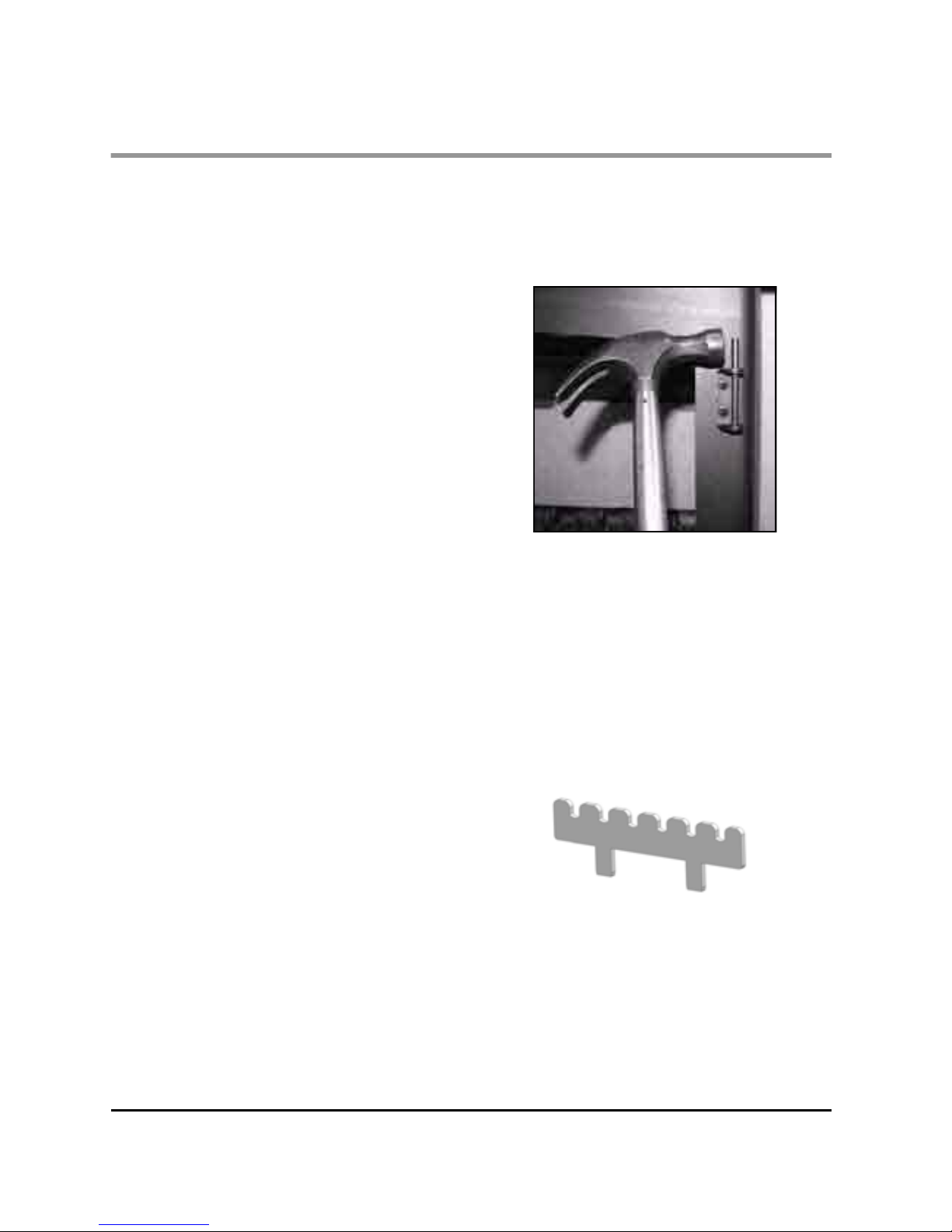
ADJUSTING THE DOOR HINGES
Once the appliance has been under fire for a
period of time the fire door may appear to have
moved out of alignment with relation to the door
aperture or catch. This is quite normal and due to
the settling of the casting.
The fire door can be re-aligned as follows :
x When the appliance is cold, open the fire door
so that it is at right angles to the front of the
stove.
x Lift the fire door up off its hinges.
x Gently tap the hinge pins in the direction to
compensate for the misalignment. (Fig. 11)
x Re-fit the door and check to ensure it now sits
square to the body; if not repeat the above
steps.
If the fire door needs to be raised,
please follow :
x When the appliance is cold, open the fire door
so that it is at right angles to the front of the
stove.
x Lift the fire door up off the hinges.
x Drop one washer on the top and bottom hinge
pins. Fit the door and check.
Please Note :
There is no adjustment to the door lock /
catch assembly.
FUEL RETAINER
A Fuel retainer is supplied with the stove.
Periodically check for any bowing or heat warp
age to the fuel retainer and replace if necessary.
Fuel retainer
Please Note :
This operation should only be carried out when
the appliance is unlit and cold.
Fig. 11. Adjusting The Door Hinges
Page 13
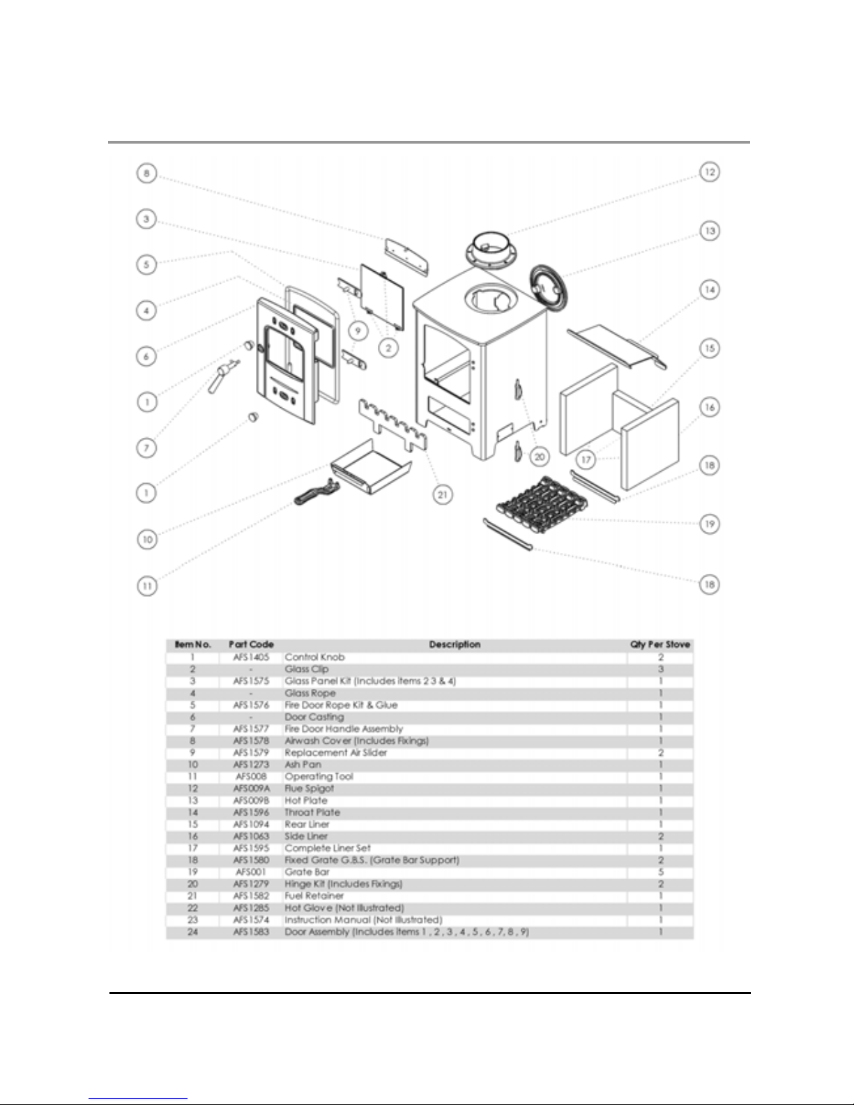
13
SERVICE & MAINTENANCE
AX1 Spare Parts
Page 14
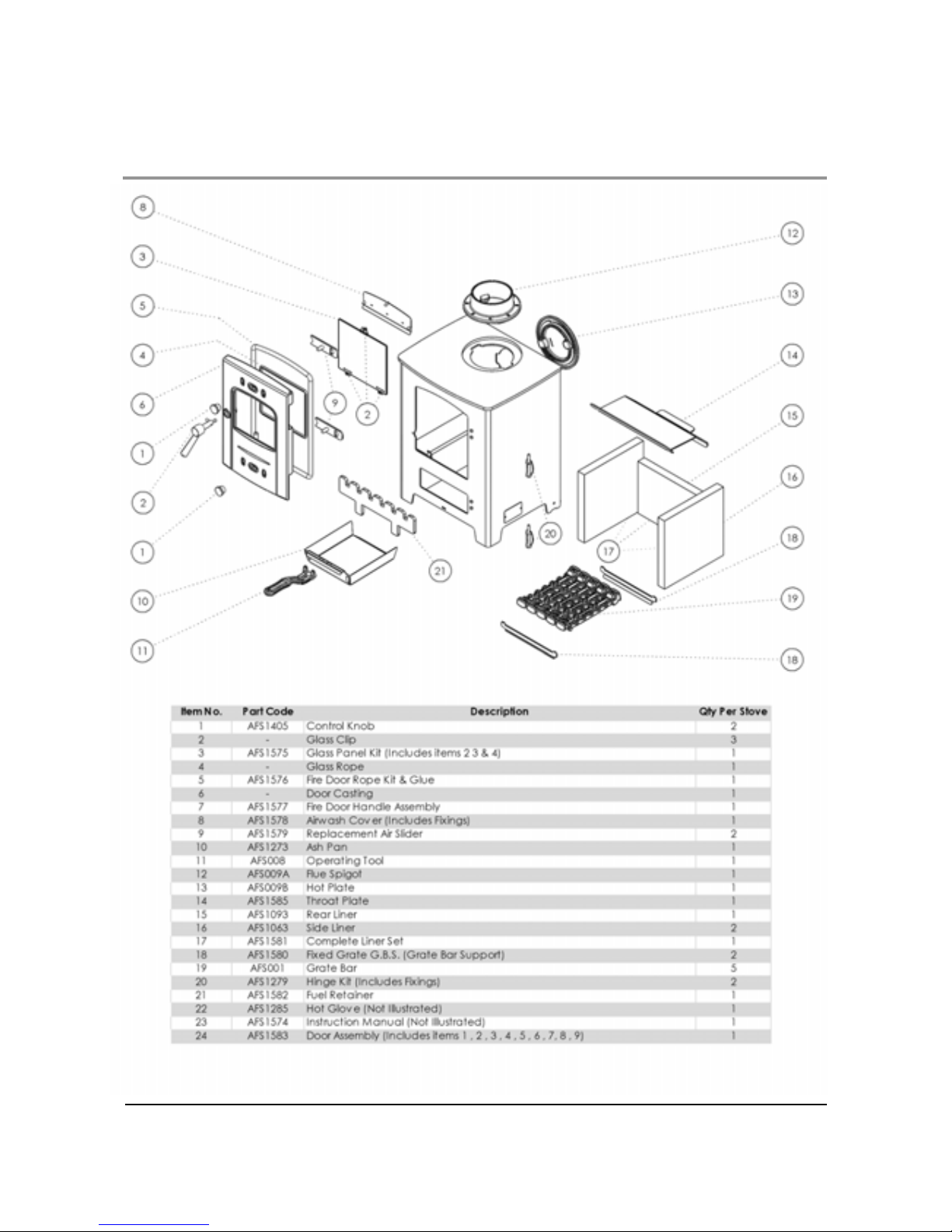
14
SERVICE & MAINTENANCE
AX2 Spare Parts
Page 15

15
GUARANTEE
Your AX range stove carries a guarantee against defects of manufacture and faulty
workmanship for a period of 12 months from date of purchase. This does not apply to items which
would be subject to fair wear and tear. Fire box liner panels, Fuel retainer, Throat plate, Door rope,
Door glass and gaskets are not covered by the guarantee. However should you have any
problems with your appliance please contact your supplier / stockist who will have the knowledge
and facilities to help you.
The Supplier / Manufacturer will not be responsible for any consequential or incidental loss,
damage, or injury however caused.
USE OF SPARE PARTS OTHER THAN THOSE SUPPLIED BY THE MANUFACTURER WILL
INVALIDATE THE APPLIANCE WARRANTY.
All Guarantee periods commence on the date of purchase and are non-transferable.
Our guarantee is offered as an addition to your statutory rights.
The guarantee is applicable to the original purchaser only and is non-transferable.
This installation and operating manual gives sufficient detail to enable the appliance to be installed
and maintained. If further information is required please contact your AX range stove supplier, or
our technical help line will be pleased to offer assistance.
Please telephone: 0844 8475107 -or email: [email protected]
When you contact the helpline, they will need to know :-
1. Your Name, Address, Post Code and Telephone Number.
2. Date of Purchase and Supplier Details..
3. Name of Installer.
4. Stove Serial Number ( located on the stove data plate on the bottom left hand side of the
stove body)
5. Clear and concise details of the Fault.
Please complete the following for you own records.
Date of Purchase……………………………………….
Name and Address of Supplier…………………………………………………………….
…………………………………………………………………………………………………
…………………………………………………………………………………………………
…………………………………………………………………………………………………
Stove Serial number.....................................................................................................
Page 16
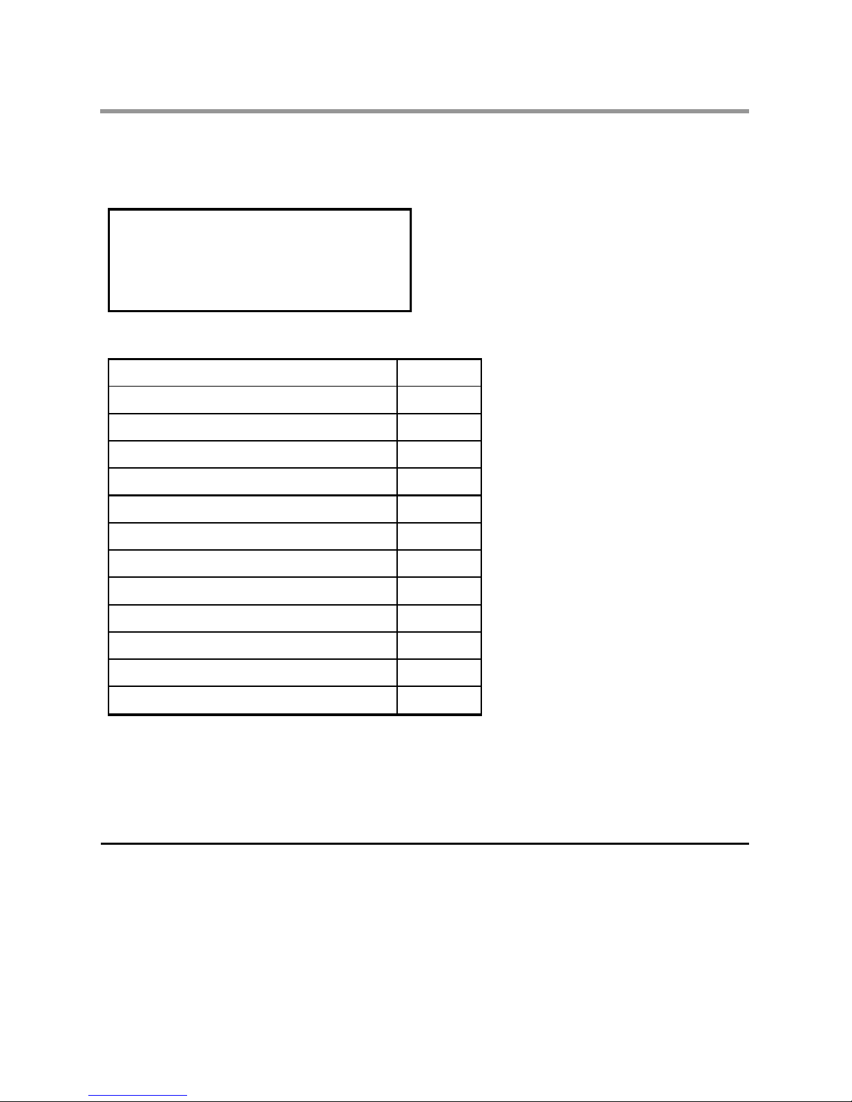
BK132
Final Factory Check list
Stove Model …………….……………...
Serial No. ……………………………….
I’ve checked it
and its O.K !
Quality / Finish
Parts
Grate Bars
Flue Outlet
Hot Plate
Fuel Retainer
Firebox Liners
Throat Plate
Air Wash
Ash Pan
Operating Tool
Stove Mitten
Operating & Installation Manual
Assembled By……………………...
Checked By………………………….
Arada Ltd
The Fire Works
Weycroft Avenue
Axminster
Devon
EX13 5HU
United Kingdom
Tel: +44(0)1297 35700 Fax: +44(0)1297 35900 www.arada.uk.com
 Loading...