


1
SCAN-LINE AQUA
OPERATING INSTRUCTIONS
UK
www.heta.dk

2
Congratulations on the purchase of
your new stove. We are confident
that you will enjoy using your new
investment, which you will get most
out of by following the advice and
instructions contained within this
guide.
Scan-Line Aqua conforms to both EN
13240 and 15a B-VG Austria.
This certification is your guarantee
For minimum clearance requirements from a flammable wall, refer
to the information plate on the
stove and the table on page 6 of this
guide.
Warning!
As your stove becomes
extremely hot during ope ration (in excess of 90°C),
please handle it with extre me caution.
Children should never touch the
stove.
Never place flammable objects under the ashpan.
Remember
1. Always ensure easy access to the
chimney cleaning hatch.
2. Ensure the room has adequate
ventilation.
3. Note that extraction fans ope-
that your new stove meets a range
of stringent specifications and requirements, which ensure it is made
from high-quality materials, is kind
to the environment and is efficient.
Your new stove is supplied with the
following:
a. Operating instructions
b. Warranty
c. A heat-resistant mitt
Installing the stove
The stove must always be installed in
accordance with applicable regulations for your particular area or
country, including installation of the
flue and connection of the stove to
it. Always consult your local chimney
sweep before carrying out installation, as you are responsible for
ensuring that all applicable regulations are complied with.
Clearance
Regulations regarding installation of
a stove near a flammable wall differ
from those for a non-flammable wall.
A stove may be positioned against
a wall made from non-flammable
material. However, to allow for sufficient cleaning space behind your
stove, we recommend a clearance of
at least 5cm from the wall.
INSTALLATION
TABLE OF CONTENTS
Installation ............................................................... .................. 2-4
Operating instructions ................................................... ........... 4-8
Connecting to a water system…..................................... ........ 9-11
Installing and commissioning Heta Aqua Kit K 36-20 .... ..... 13-17
Schematic diagrams............................................................ ... 18-19

3
rating in the same room as the
stove can weaken the chimney
draught, which can effect the
stove’s efficiency. It can also lead
to smoke escaping into the room
when opening the firing door
4. D
o not cover the air vents, if fitted.
Floor surface
Ensure the floor can bear the weight
of the stove and top-mounted steel
chimney, if applicable. The stove
must stand on a non-flammable surface such as steel plate or brick/tile.
The dimensions of the non-flammable surface used to cover the floor
area must comply with applicable
regulations for your particular area
or country.
Chimney connection
The chimney opening must comply
with national and local regulations.
However, the area of the opening
should not be less than 175 cm2,
which corresponds to a diameter of
150 mm. If a damper is fitted to the
flue gas pipe, there must be at least
20 cm2 of free passage when in the
closed position. If local regulations
permit, two closed fireplaces may
be connected to the same chimney.
However, you must be aware of local
regulations regarding how closely
they may be located to each other.
Stoves must never be connected to a
chimney that already has a gas-fired
heater connected to it.
An efficient stove places high demands on a chimney. Therefore, always have your local chimney sweep
assess the condition of your chimney
Connecting to a brick chimney
Build a thimble into the chimney
to accommodate the flue gas pipe.
The thimble and flue gas pipe must
not penetrate the chimney opening
itself, but must be flush with the inside of the chimney duct. The points
where brickwork, thimble and flue
gas pipe meet must be sealed with
fireproof material/beading.
Connecting to a steel chimney
When connecting a top-outlet stove
directly to a steel chimney, we recommend feeding the chimney pipe
inside the connecting pipe from the
stove, which will allow soot and
condensation to drop into the stove
itself rather than collecting on the
outside surface.
An installation must comply with applicable national and local regulations where a chimney is fed through
an internal ceiling. To avoid overloading the stove, it is important that
the chimney is supported by a loadbearing roof support.
Draught conditions
Poor draught may result in smoke
escaping from the stove when the
door is opened.
To ensure satisfactory combustion,
chimney draught for this oven should
be at least 10 PA, although some
smoke may still escape if the firing
door is opened when the stove is
burning strongly.
The nominal flue gas operating temperature is 236°C with an outdoor
temperature of 20°C.
The flue gas mass flow is 14.7 g/sec.
Chimney draught is generated by
the difference between the high
chimney temperature and low outdoor temperature.
The chimney’s length and insulation

4
- the chimney and flue gas pipe are
blocked
- the house is sealed (no through-
draught)
- negative pressure (poor draught
conditions) due to a cold chimney
or bad weather conditions can be
compensated for by increasing the
airflow into the stove.
Good draught occurs when:
- there is a significant difference in
temperature between the chimney
and outdoor air
- the weather conditions are clear
- there is a strong wind
- the chimney is at the correct height
of at least 4 m above the stove and
free of the roof ridge
as well as the ambient wind and
weather conditions also affect the
ability to generate sufficient negative pressure in the chimney.
Before lighting a stove that has not
been used for a long time, check
that the chimney and stove are not
blocked with soot, bird nests, etc.
Reduced draught can occur
when:
- the temperature difference is too
small, e.g. due to insufficient chimney insulation
- the outdoor temperature is too
high, e.g. during the summer.
- there is no wind outside
- the chimney is too low and is sheltered from the wind
- there is false air in the chimney
OPERATING INSTRUCTIONS
First firing
Your stove is treated with heatresistant paint, which hardens at a temperature of approx. 250°C. Ensure
the room is well ventilated, as the
hardening process produces a certain
amount of fumes and smell.
The firing door should remain slightly open during the first 1–2 firings
with around 1 kg wood and should
not be closed until the stove is cold.
This is to prevent the beading from
becoming stuck to the stove.
Wood fuel
The stove is EN approved for the
firing of wood fuel. You must therefore only burn clean, dry wood in
your stove. Never use your stove to
burn driftwood, as it may contain a
significant amount of salt, which can
damage both your stove and chimney. You must also avoid burning
rubbish, painted wood, pressureimpregnated wood or chipboard,
as these materials can release toxic
fumes and vapours. Correct firing
produces optimal heat and efficiency. It also avoids problematic smells
and smoke being released into the
atmosphere and reduces the risk of
chimney fire.
When burning damp wood, a large
proportion of the heat is wasted
during evaporation of the water.
Firing with damp wood is therefore
not only uneconomical, it also increases the risk of tarry soot, smoke
and environmental problems. Therefore, it is important to use dry wood,
i.e. wood with no more than 18 %
moisture content. This is achieved by
storing the wood for 1-2 years before use. Firewood with a diameter
of more than 10 cm should be split

5
Fig. 1 Fig. 2
Open Closed
before storage, and should be of an
appropriate length (approx. 22–30
cm) so they can be laid evenly on the
embers. Firewood stored outdoors
should be covered.
Examples of combustion values for
different woods
Wood type in cubic metres
equivalent to 1,000 litres of oil
Oak Beech Ash Birch Elm Spruce
7,0 7,0 7,2 8,0 8,9 10,4
Chimney fires
In the event of a chimney fire, close
the firing door and shut off the
secondary/start-up air to smother
the fire. Then call the fire service
immediately. Chimney fires are often
caused by incorrect operation or
long-term use of damp wood.
Regulating the air supply
Open the secondary air by moving
the operating handle at the back
of the side panel. Fig. 1 shows the
secondary air fully open. Gradually
shut off the secondary air by lowering the handle. The air supply is
fully shut off when the handle is as
shown in Fig. 2.
Open the start-up air to the stove by
sliding the start-up handle fully to
the right (front view). See Fig. 3.
Shut off the start-up air by sliding
Fig. 3 Fig. 4
Oben
Closed
the start-up handle fully to the left
(front view). See Fig. 4.
Igniting
To ignite the wood, place firelighters,
small paraffin ignition bags or small
pieces of firewood on the bottom
grate. Then place larger pieces of
firewood on top of the kindling
material perpendicular to the firing
door. Fully open the secondary air
and leave the firing door slightly
open (approx. 1 cm).
When the fire is burning with a steady flame and the chimney has heated
up (after about 10 min), close the
firing door. We recommend leaving
the secondary air fully open throughout the first firing, to ensure that
the stove and chimney are heated
thoroughly.
Stoking
We recommend stoking the stove
while there is still a good layer of
embers. Spread the embers across the
bottom grate and place up to 2 kg of
firewood on the embers in a single
layer perpendicular to the firing opening. Close the firing door and feed
in start-up air if required. The wood
will then ignite within 30–60 seconds.
When the wood is burning with a
steady flame, shut off the start-up air
if open. Then adjust the secondary
air to the required level. Nominal
operation (12 kW) is achieved when
the secondary air is fully open and

6
Stove data as per EN 13240 testing. Scan-Line Aqua
Particle
emission
mg/m
3
CO
%
Flue gas
mass
flow
g/s
Nominal
flue gas
temp.
c°
Flue
connector
pipe
mm ø
Firing
weight
kg
Draugh
min
mbar
Nominal
output
kW
PowerkWDistance to flammable
materials in mm
behind at the
the stove sides
Minimum
distance from
furniture
mm
Stove
weight
kg
55
0,07*
14,7 236
150
2 0,10 12 12 150 300 1000
160
* 0,07% - (875 mg/nm3)
The nominal heating effect is the effect at which the oven has been tested.
Testing was carried out with the secondary air fully open and start-up air fully closed.
the primary air is shut off. When
firing, do not place the wood too
closely together, as this will result in
poor and therefore less cost-effective combustion. Note that the startup air must not remain open during
normal operation, as overheating
may occur. It should therefore be
shut off when the wood is burning
with a steady flame.
Reduced combustion
To operate the stove with reduced
output, simply use a smaller amount
of wood when firing and reduce the
air supply. However, remember that
the secondary air must never be shut
off completely during firing, and it is
important to ensure that the embers
remain hot. Moderate heat is achieved when the fire settles, i.e. when
no more flames are visible and the
wood has become glowing charcoal.
Optimal firing
To achieve the most effective firing,
it is important for the air to be fed
in correctly. As a general rule, the
fire should be controlled by the secondary air so that it ignites the flue
gases. The secondary air circulating
inside the stove also prevents the
formation of soot on the glass panel. Note that sooting is inevitable
if both the start-up and secondary
air is shut off. When damp wood is
combined with the conditions described above, the soot can become
extensive and adhesive enough to
pull the door beading off when the
door is next opened.
Risk of explosion!!!
After placing wood in the
stove, it is very important
not to leave the stove un attended until it is burning
with a steady flame (nor mally within 30–60 seconds).
The large amount of gas produced
by adding an excessive amount of
wood, combined with insufficient air
supply, may lead to a risk of explosion. We also recommend leaving
a layer of ash at the bottom of the
combustion chamber.
Use caution when emptying the
ashpan. Hot embers can remain in
the ash for a long time.

7
BLOCKAGE
If smells or smoke escape from the
stove, it is important to establish
whether the chimney is blocked. A
small amount of draught is always
required to ensure satisfactory operation. However, note that chimney
draught is dependent on the outside
wind conditions. It may be necessary to fit a damper in the flue gas
pipe to regulate the draught in high
wind conditions. When sweeping
MAINTENANCE
Your stove is surface treated with
heat-resistant lacquer and should be
cleaned using a damp cloth. Commercially-available repair spray can
be used to repair damage to the
lacquer surface.
Cleaning the glass
Inefficient firing resulting from the
use of damp wood, etc. can lead to
sooting of the glass panel. However,
this can be removed easily using special glass cleaner or standard scouring liquid.
the chimney, be aware that soot, etc.
can collect in the smoke chamber
behind the stones. Excessive chimney
draught may cause wood to burn
too quickly. Also check the condition
of the door beading. Using damp
wood may produce insufficient heat,
as much of the heat energy is used
to dry the wood, which results in
increased heating costs and greater
risk of chimney sooting.

8
Emptying the ashpan (Figs. 5-8)
5
6
7 8
Clearing soot after chimney sweeping and replacing the stones. (Figs. 9-12).
9
10
11
12
Warning
Unauthorised modification
of the stove and the use of
non-original parts will void
your warranty.
WARRANTY
Heta stoves undergo extensive
quality control before delivery
to our suppliers.
Your product is therefore guaranteed for 5 years against manufacturing
defects.
Your warranty does not cover:
- Consumables/breakable parts,
including: Fireproof stones in the
combustion chamber, glass, fire
rope and grate
- Damage resulting from incorrect
use
- Disassembly, transportation and re-
installation costs associated with a
warranty repair
Should you have cause to make a complaint, please quote our invoice no.

9
Attaching an outside air supply
(if required) Figs. 5–8.
Cut out and remove the metal cover
plate as shown using a diagonal
cutter.
Feed a duct through the hole in the
back plate.
Push the duct onto the ø100 mm
pipe welded behind the ashpan.
Secure the duct using a collar band.
Fig. 13
Fig. 14
Fig. 15
Fig. 16

10
CONNECTING TO A WATER SYSTEM
Aqua: Applications and
conditions of use.
Fig. 1 Scan-Line 580
The important information contained within this guide does not
encompass every situation. Common
sense and good workmanship, together with professional installation
and correct maintenance, will ensure
the reliability of your stove.
As Heta A/S is unable to give advice
on every type of installation, we have
produced this guide to help you
choose the best method of installing
your stove.
An AQUA stove gives you even more
possibilities than with a standard
stove, allowing you to have hot water, radiators and even floor heating
anywhere in the house.
You do, however, have to bear in
mind a few things:
The installation may only be carried
out by an authorised plumber and
must comply with all applicable legislation. You must also have a basic
understanding of how the stove
works. Do not install a stopcock between the stove and the rest of the
heating system. Incorrect operation
of the system may overheat the water and prevent it from circulating.
Never fire the stove while the boiler
is empty, as this may cause the copper cooling pipes to leak. Air trapped within the boiler may also lead
to a risk of explosion. To get the
best out of your heating system and
maintain efficient burning, we recommend that you use Heta’s AQUA
Kit, which releases water into the
system only when the stove reaches
the right temperature.
An AQUA stove must always be
fitted with an expansion tank, of
which there are two types: open
expansion and closed expansion.
Fig. 2 A: Open expansion tank
Fig. 2 B: Closed expansion tank
1: Vent pipe. 2 and 6: Tank.
3 and 8: Water. 4 and
9: Connection to system.
5: Pressurised air.
7: Membrane
.

11
Open expansion means that the
expansion tank (in this case located
at the top of the installation) is
open to the atmosphere. It must be
large enough to accommodate the
volume of expanded hot water in
the system. If the circulation in the
system stops while the stove is lit,
the temperature will rise sharply.
It is therefore necessary to protect
against excess pressure. An open
expansion tank that is correctly and
installed and of sufficient size protects against this by releasing excess
pressure to the atmosphere through
a vent pipe. The disadvantage of
open expansion is that the expansion tank must be located above the
rest of the system. The tank (and
access pipe) must also be protected
against frost, and oxygenation of
the water also necessitates some
form of corrosion protection within
the system.
With closed expansion, the expansion tank is hermetically sealed and
fitted with a membrane, which accommodates changes in water volume by compressing the air stored
on the other side of the membrane.
The advantage of this system is that
the expansion tank can be located
anywhere in the system. Also, as the
system is hermetically sealed, it is
not liable to the same oxygenation
problems of the open expansion
system. However, this system does
not protect against excess pressure
resulting from, for example, overheating. It is therefore necessary to
install some form of protection that
complies with relevant legislation.
For a closed expansion system, this
normally consists of a pressure relief
valve and emergency cooling circuit. The emergency cooling circuit
consists of a spiral-shaped pipe
built into the water tank, which is
connected directly to a cold water
supply at one end, running out to a
drain via a thermostat at the other.
The thermostat sensor is located in a
holder within the tank.
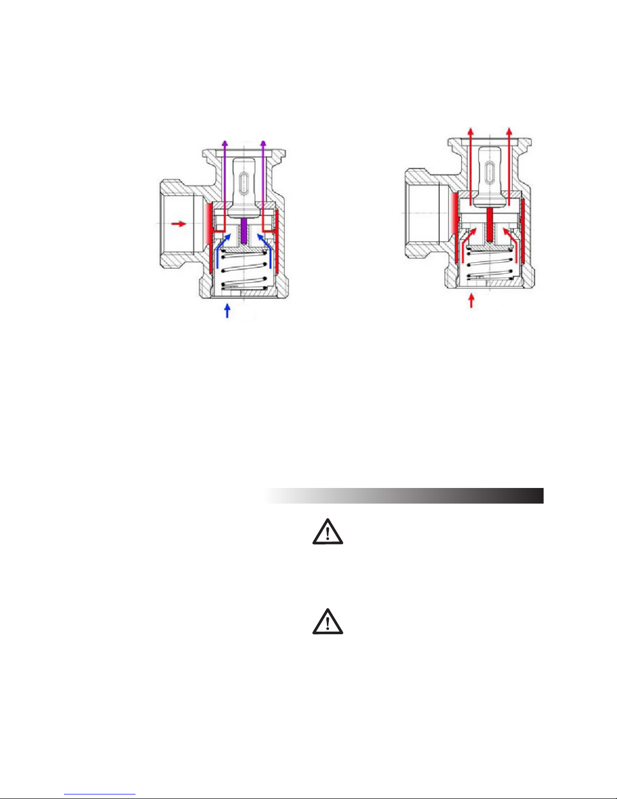
Fig. 3 Emergency cooling circuit
1: Temperature control valve
2: Sensor
3: Cold water supply
4: Tank
5: Cooling coil
6: Drain
7 and 8: Flow and return
9: Pressure relief valve
If the system overheats, the thermostat will open at 95ºC, allowing cold
water to run through the cooling
coil to cool the tank. If this is insufficient, for example if the cold water
supply is stopped, the temperature
will continue to rise until the pressure causes the pressure relief valve
to open, allowing built-up steam to
escape.
If pockets of air become trapped
in the water system, there is a risk
that the water may stop circulating,
which in turn can lead to overheat-

12
ing. We therefore recommend installing an automatic air vent to allow
trapped air to escape.
Fig. 4 Example of an automatic air
vent
1: Tank
2: Air pocket preventing circulation
3: Automatic air vent (in this case, open)
A stove fitted with a water tank
may cause increased cooling of the
smoke, which can lead to problems
with chimney draught. Therefore, it
is important to use additional kindling and to leave the door slightly
open for longer than normal, so the
water in the tank can be heated as
quickly as possible. A system should
also be installed to maintain the correct temperature. We recommend a
system comprised of a thermostatic
switch and a circulation thermostat,
which ensure that water starts circulating only when it has reached the
required temperature.
Fig. 5 System for maintaining the
correct temperature
1: Cold water return
2: Hot water supply
3: Circulation thermostat
4: Thermostatic switch
5: Circulation pump
a: Circuit at 60°C
b: Circuit over 60°C
The circulation pump starts when
the water temperature in the tank
reaches 50ºC. At this temperature,
circulation only occurs in the tank/
Aqua kit, as the thermostat (Figs.
5,3) will not open and release water
to the rest of the system until the
tank temperature reaches 60ºC. This
process stops and starts the system
automatically. Therefore, you only
have to ensure that at least one
component that is able to dissipate
the heat is attached to the system,
such as an accumulation tank or an
open radiator.

13
Aqua kit K36-20
See special instructions for
Aqua kit on page 14
Connection
1
2
3
5
4
6
1. Water to drain. 12 mm copper pipe
2. Water connection.
Thermal cooling protection.
12 mm copper pipe
3. Return (cold) 1” RG
4. Flow (hot) 1” RG
5. Extra 1” RG
6. Submersible thermostat connector
1/2” RG
Submersible
thermostat0006-5009 TC 2
– E11513
SYR temperature valve
0006-5005 ¾”
3-way valve
K36-20 with
60° opening
Thermometer
– red
0006-5010
Bleed
valve
Pressure relief
valve
Grundfos
pump
UPS 15-40
Thermometer
blue
0006-5011
Example: Opened and closed expansion systems
Thermal protection*
Water connection*
Radiator and /
or floor heating
Central gas
or oil boiler
Thermostat /
Pump / Valve
Temperature sensor
Drain*
*Closed expansion

14
INSTALLING AND COMMISSIONING HETA
AQUA KIT K 36-20
1. GENERAL
1.1 Scope
These instructions describe the
function, installation, commissioning
and operation of Heta return-flow
temperature controller K36-20. For
other components such as regulators, refer to the relevant manufacturer’s documentation.
Sections marked with [Expert] are
intended for use by qualified professionals.
Please read these instructions
thoroughly before using the loading
valve assembly for the first time and
store them safely for future reference.
1.2 Product description
Heta return-flow loading valve
assembly K36-20 is a pre-installed fixture that maintains constant return
water temperature in Heta recessed
fireplaces and stoves.
• Ballcocks with integrated thermometer (flow and return)
• Pressure relief valve to prevent
excessive pressure
• Automatic bleed valve to prevent
air/gas bubbles in the heat exchanger
• Submersible thermostat to turn
the pump on and off depending
on temperature
• Thermal control valve with 60°C
opening temperature
Our packaging is made from recyclable materials.
1.3 Functional description
Heta return-flow loading valve assembly K36-20 prevents the boiler
from sooting by raising the return
water temperature with the help of
a thermal valve (through a bypass).
The constant return-flow temperature ensures even combustion and
optimal energy utilisation.
1. As long as the water temperature
in the boiler circuit remains below
the control valve opening temperature, the valve will prevent water
flowing into the accumulation tank.
The pump circulates the water in
the boiler circuit via the bypass, and
as there is less water in the boiler
circuit, it heats up more quickly.
tKR > tPR
tKR = tFIX
tKR < tBY
2. When the temperature in the boiler circuit reaches the control valve
opening temperature, it reduces the
bypass volume flow and opens the
accumulation tank circuit. The cold
return water from the accumulation
tank then mixes with the hot water
T
KR
T
BY
T
PR
15
from the boiler circuit in the control valve. This maintains constant
return-flow temperature to the
boiler and prevents the formation of
condensation in the boiler.
tKR > tFIX
tKR = tBY
3. When the return-flow temperature from the accumulation tank
exceeds the valve opening temperature, the control valve closes the
bypass completely. This allows the
water from the accumulation tank
to flow directly into the boiler.
tKR > tFIX
tKR = tPR
Temperatures: tBY = boiler flow
(bypass) tKR = boiler return flow
tPR = accumulation tank return flow
tFIX = opening temperature
2 SAFETY INSTRUCTIONS
Installation, commissioning and connection of the electrical components
require expert professional knowledge equivalent to that of an authorised plumber, heating installation
engineer, environmental technician
or equivalent. The following must
be adhered to when carrying out
installation and commissioning:
• relevant regional and national
regulations
• trade association regulations relating to safety at work
• general/safety instructions provided in this document
The person or contractor
carrying the installation is
responsible for ensuring it is
carried out correctly!
Note:
Risk of damage to materials
from mineral oil!
The EPDM seals must never come
into contact with substances containing mineral oil, as this will damage
the material and reduce its sealing
properties. If you are in any doubt,
contact the product manufacturer.
to determine whether solar fluid,
t
KR
t
BY
t
PR
t
KR
t
BY
t
PR

16
3 ASSEMBLY AND INSTALLATION [Expert]
3.1 Assembly of return-flow
loading valve assembly
1. Seal 1” double nipple in the
return-flow connector (no. 3).
2. Seal the safety section with the
vent to the extra connector (no.
4). The safety section is protected
by a lock nut. The cross joint can
be adjusted when the lock nut has
been loosened.
3. Seal the 1“ AG x ½“ IG reduction
section to the flow connector (no.
5). The immersion thermostat shell
can be sealed to the reduction
section.
4. Install the pre-assembled returnflow loading valve assembly.
Remember to fit the seals!
Start with the safety section.
First, connect everything and
1.
2.
3.
tighten by hand. Then align the
assembly and connect the pipes
(see connection diagram on the
following page). Before commissioning/pressure testing, be sure to
check and tighten all connections.
5. Connect the submersible thermostat as described in the separate
instructions and secure it.
6. Piping/connection diagram
KA
KW
grease or other products used
during installation contain mineral
oil. We accept no responsibility and
do not guarantee against damage
resulting from seals that have become damaged through exposure to
mineral oil.
Connection option A
Storage tank
Connection option B
Central heating system
Rückflusssperre

17
3.2 Electrical connection of return-flow loading valve assembly:
Wiring of submersible
thermostat connectors
The stove must never be used
without water and a functioning cold water supply [KV]
/ drain [KA] in the thermal
drain protection and relevant
safety fixtures. Otherwise,
Thermostat
Setting at ~ 55ºC
Heating pump
there is a risk of explosion, leading
to irreparable damage!
Note: Thermal drain protection is
not mandatory in Denmark when
using open expansion.

18
4 TECHNICAL DATA
Return-flow loading valve K36 DN 20
________________________________________________
Connectors
on heat production equipment: 1” external thread
to accumulation tank ¾” internal thread
________________________________________________
Materials
Fixtures brass
Seals EPDM/paper
Insulation EPP
Hydraulics
Max. temperature: 110°C
Max. pressure 4 bar
Kvs value 5.3
________________________________________________
5 PERFORMANCE
The stove has an output of approx. 3 kW on the water.
Which equates to:
- 130 l water flow per hour at 20°C between the thermometers
- 172.5 l water flow per hour at 15°C between the thermometers
- 260 l water flow per hour at 10°C between the thermometers
The installed pump (Grundfos UPS 15-40) is triggered
- at level III (at 520 l/h) at approx. 3.2 m WS (pressure loss)
this equates to approx. 40 m of Ø 18 x 1.5 mm copper pipe.
- at level II (at 520 l/h) at approx. 2.5 m WS (pressure loss)
this equates to approx. 30 m of Ø 18 x 1.5 mm copper pipe.
- at level I (at 520 l/h) at approx. 1.3 m WS (pressure loss)
this equates to approx. 15 m of Ø 18 x 1.5 mm copper pipe.
As a rule, the pump is capable of running at level I.

19
Jupitervej 22
7620 Lemvig
Tlf. 96630600
Fax 96630616
Teg type
Teg
Godk
.
Bukke nummer
Mål uden tolerancer efter DS/ISO 2768-1-m
Buk 1
8038-0002-00.asm
Scanline 580 Aqua
8038-0002-00
Samlingstegning
04-11-2007
Vægt
Materiale type
170,7 kg
Solid Edge
Saml.
SBS
8038-0002-00-plance.dft
Areal
25-08-2008
Buk 2
Skære nummer
Valseindstilling
Sidst opdateret
1 2
Valsetryk
Montere
Bearbejdning
1265
500
977
A
DETAIL A
66
143
31
121
271
299
101
1515
2
1
3
5
4
6
2
1
1 12 mm . Thermische Ablaufsicherung-Einlauf Kaltwasser
2 12 mm . Thermische Ablaufsicherung-Auslauf Kaltwasser
3 1" IG. Kessel Rücklauf
4 1" IG. Kessel Vorlauf.
5 1" IG. Exstra.
6 1/2 Muffe Tauchhülse der Thermichen Ablaufsicherung
1 Cu-rør for vand til afløb - kogningssikring - For lukket anlæg.
2 Cu-rør for vandtilslutning - Termostatsikring for kogning.
3 Retur (kold). 1" RG.
4 Fremløb (varm). 1" RG.
5 Ekstra 1" RG.
6 Dykrør 1/2" RG.
DETAIL A
1 Copper pipe for water to drain
- boil protection - For closed systems
2 Copper pipe for water connection
- Thermostatic boil protection
3 Return (cold) 1” RG
4 Flow (hot) 1” RG
5 Extra 1” RG
6 1/2” RG submersible connector

20
462,1
2
7
Pos.
Nr.
Vare Nr. Titel Materiale Antal
1* 0008-0003 M6 x 20 rundhoved 1
2 0008-0040 M5 X 10 unbrako 2
3 0008-1201 M6x16 Sekskantskrue elforzinket 2
4* 0008-1402 Møtrik M6 el forz. 1
5 0020-3024 Rensesektion 1
6 0023-0075 Røgvender Støbt Skamolsten 1
7 1013-0396 Løftekrog til bundrist Blankt rundstål ø6 0004-1403 1
8 1523-0021 Heta Stensæt for SL-500 Saml. 1
9 1525-0001 Røgtud Tysk udgave 1
10 4530-1104 Compact Line aqua formontage Saml. 1
11 5005-0024 Låge Kompakt Line Saml. 1
510,5
96
Jupitervej 22
7620 Lemvig
Tlf. 96630600
Fax 96630616
Teg type
Teg
Godk
.
Bukke nummer
Mål uden tolerancer efter DS/ISO 2768-1-m
Buk 1
7108-0001.asm
Kompakt Line Aqua
7108-0001
Samlingstegning
16-06-2008
Vægt
Materiale type
92,6 kg
Solid Edge
Saml.
LSK
7108-0001.dft
Areal
11-08-2008
Buk 2
Skære nummer
Valseindstilling
Sidst opdateret
1 2
Valsetryk
Montere
Bearbejdning
3
10
145,6
20
8
5
1325,1 308
514,1
6
11
9
165,5
23-10-2009 0037-1162
 Loading...