

Page 1
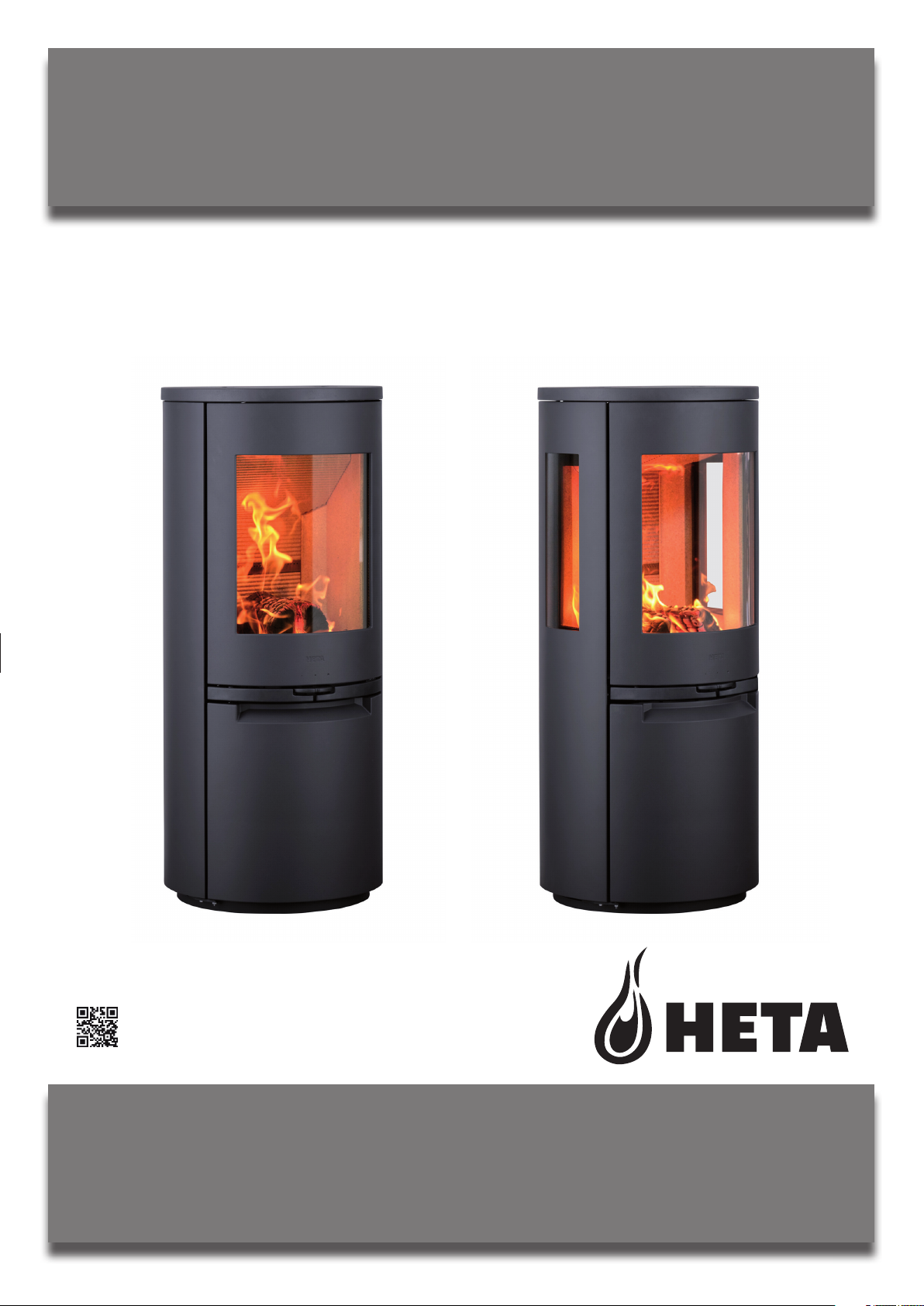
OPERATING AND INSTALLATION
INSTRUCTIONS
SCAN-LINE 900 / SCAN-LINE 900 SCA
Scan-line 900 SCA is exempt for use in smoke control areas when burning dry wood
PENDING
www.heta.dk
DANISH DESIGN . DANISH QUALITY . DANISH PRODUCTION
ECODESIGN READY
EN
1
Page 2
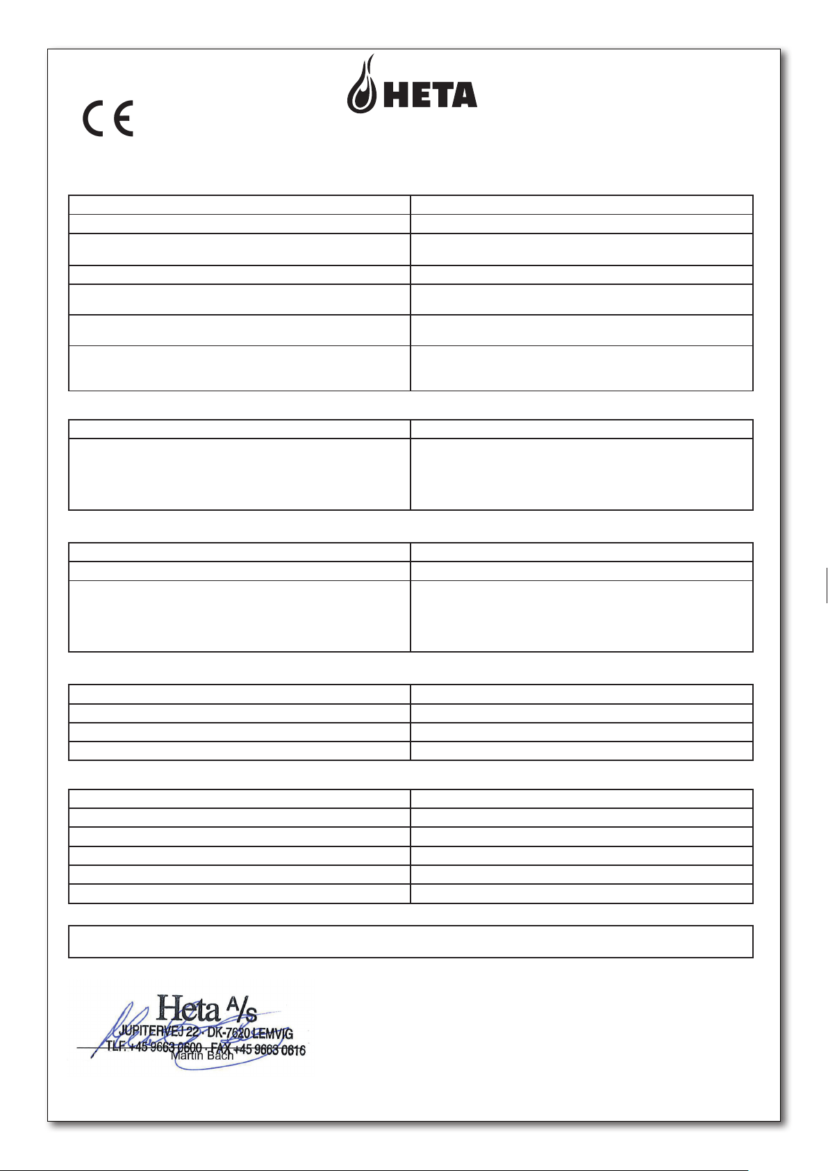
Certifikat no. 2409
Declaration of Performance EN
__________________________________________________________________________________________________________________________________
Regulation No. 305/2011
DOP-Scan-Line 900 2409-2019
1. Unique identification code of product-type Stove
2. Product name Scan-Line 900
3. Intended use or uses of the construction product, in
accordance with the applicable technical specification
4. Name and contact address of the manufacturer Heta A/S, Jupitervej 22, DK-7620 Lemvig. heta@heta.dk
5. Where applicable, name and contact address of
authorized representative. E-mail.
6. System of assessment and verification of constancy of
performance of the construction product
7. Notified body relevant to the assessment and
verification of constancy of performance
8. Declared Performance
Harmonized technical specification EN 13240:2001/A2:2004
Emission CO 0,04% / 513 mg/Nm³
Fire safety
Reaction to fire A1
Test of fire safety in connection with the burning of wood Approved
Distance to combustible materials
Rear. Without insulation / with insulation
Sides distance to combustible materials
Distance to floor from lower edge of the door
Furniture distance
Safety
Mechanical resistance (to carry a chimney / flue) Not tested (NPD)
Electrical safety NA
Surface temperature Approved
Cleanability No specification
Room heater burning solid fuel without hot water supply
Factory Manager Martin Bach, E-mail: martin.bach@heta.dk
System 3
Teknologisk Institut, DK-8000 Aarhus
Notified body No. 1235
Rapport no. 300-ELAB-2409-EN
Nox 91 mg/Nm
Dust 7 mg/Nm
Dust (NS3058/3059) 1,22 g/kg
OGC (CEN/TS 15883) 25 mgC/Nm
3
3
3
ved 13% O
2
Minimum distances in mm
175/175
350
---1000
Thermal output
Nominal heat output 6,6 kW
Room heat output 6,6 kW
Energy efficiency
Fluegas temperature at nominal heat output T 252
Ƞ 83%
o
C - at 20° C room temperature
Water heating output NA
Maximum water operating pressure NA
9.
The performance of the product identified in points1 and 2 is in conformity with the declared performance in point 8. This
declaration of performance is issued under the sole responsibility of the manufacturer.
Signed on behalf the manufacturer of 06.06-2019
____________________________________________________________________________________________________________________
In case of any change of the above-mentioned production type this Declaration of Performance becomes invalid.
Heta A/S, Jupitervej 22, DK-7620 Lemvig, Tlf. +45 9663 0600, www.heta.dk
Page 1 of 1
2
Page 3
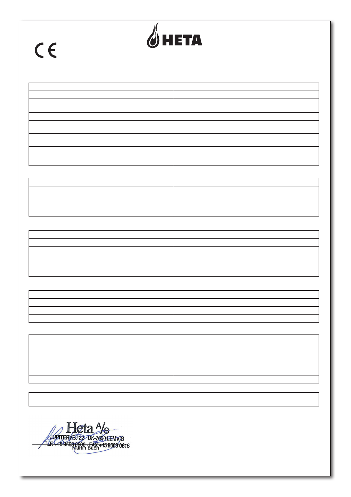
Certifikat no. 2408
Declaration of Performance EN
__________________________________________________________________________________________________________________________________
Regulation No. 305/2011
DOP-Scan-Line 900 Side glass 2408-2019
1. Unique identification code of product-type Stove
2. Product name Scan-Line 900 Side glass
3. Intended use or uses of the construction product, in
accordance with the applicable technical specification
4. Name and contact address of the manufacturer Heta A/S, Jupitervej 22, DK-7620 Lemvig. heta@heta.dk
5. Where applicable, name and contact address of
authorized representative. E-mail.
6. System of assessment and verification of constancy of
performance of the construction product
7. Notified body relevant to the assessment and
verification of constancy of performance
8. Declared Performance
Harmonized technical specification EN 13240:2001/A2:2004
Emission CO 0,09% / 1160 mg/Nm³
Fire safety
Reaction to fire A1
Test of fire safety in connection with the burning of wood Approved
Distance to combustible materials
Rear. Without insulation / with insulation
Sides distance to combustible materials
Distance to floor from lower edge of the door
Furniture distance
Safety
Mechanical resistance (to carry a chimney / flue) Not tested (NPD)
Electrical safety NA
Surface temperature Approved
Cleanability No specification
Room heater burning solid fuel without hot water supply
Factory Manager Martin Bach, E-mail: martin.bach@heta.dk
System 3
Teknologisk Institut, DK-8000 Aarhus
Notified body No. 1235
Rapport no. 300-ELAB-2408-EN
Nox 75 mg/Nm
Dust 7 mg/Nm
Dust (NS3058/3059) 2,44 g/kg
OGC (CEN/TS 15883) 88 mgC/Nm
3
3
3
ved 13% O
2
Minimum distances in mm
150/125
400
---900
Thermal output
Nominal heat output 6,6 kW
Room heat output 6,6 kW
Energy efficiency
Fluegas temperature at nominal heat output T 267
Ƞ 81%
o
C - at 20° C room temperature
Water heating output NA
Maximum water operating pressure NA
9.
The performance of the product identified in points1 and 2 is in conformity with the declared performance in point 8. This
declaration of performance is issued under the sole responsibility of the manufacturer.
Signed on behalf the manufacturer of 06.06-2019
____________________________________________________________________________________________________________________
In case of any change of the above-mentioned production type this Declaration of Performance becomes invalid.
Heta A/S, Jupitervej 22, DK-7620 Lemvig, Tlf. +45 9663 0600, www.heta.dk
Page 1 of 1
3
Page 4

Congratulations on your new wood stove, we are confident that you will be more than
satisfied with your new Heta stove. Especially if you follow the following advice and
instructions.
Scan-Line 900 and Scan-Line 900 Side windows have been approved according to
the EN 13240, NS 3058, NS 3059 and A15 Austria. and the Scan-Line 900 SCA series
are modified so that they are also recommended as exempt for use within smoke
control areas (SCA) throughout the UK (see clean air act Appendix A). of the air supply regulation so that it can`t be closed completely.
Operating Instructions Contents
Declaration of Performance ........................................................... 2-3
Before installation ........................................................................... 5-6
1. Operating instructions ........................................................................ 7
1.1 Before using ....................................................................................... 7
1.2 First firing ........................................................................................... 7
1.3 Regulating the airflow ......................................................................... 7
1.4 Lighting the stove ............................................................................... 7
1.5 Refueling ............................................................................................ 7
1.6 Emptying the ash ............................................................................... 8
1.7 Reduced burning ................................................................................ 8
1.8 Risk of explosion ................................................................................ 8
1.9 Draft conditions in the chimney ......................................................... 8
1.10 Fuel ................................................................................................... 10
1.11 Operating problems ......................................................................... 11
1.12 Chimney fire ..................................................................................... 11
1.13 Maintenance ..................................................................................... 11
1.14 Cleaning the glass ............................................................................ 11
1.15 Diagram for maintenance ................................................................. 12
1.16 Troubleshooting ............................................................................... 13
1.17 Cleaning/Replacing bicks after chimney sweeping Scan-Line 900 . 14
1.17 Cleaning/Replacing bicks after chimney sweeping
Scan-Line 900 Side windows ........................................................... 15
1.18 Stove data table EN 13240 .............................................................. 16
1.19 Garantee ........................................................................................... 16
1.20 Parts ............................................................................................ 17-19
2. Installation Instructions .................................................................... 20
Heta A/S
Jupitervej 22,
DK-7620 Lemvig
Phone: +45 9663 0600
E-mail: [email protected]
4
Copyright © 2014
Heta is a registered
trademark of Heta A/S
Printed in Denmark
Subject to printing errors
and changes.
06.11.2019
0037-1545 Version 1,5
Page 5

BEFORE INSTALLATION
Heta wood stoves are quality products, therefore, your first impression is very important! We have
a good logistics network, which transports Heta products with great care for our dealers. Nevertheless, when in transport or handling, damage of the often-heavy stoves can occur. It is important that
upon receipt check your Heta product completely and report any damage or defects to your dealer.
The packaging must be disposed of as follows:
Wood is untreated and able to burn in the stove.
Plastic and cardboard you can drop off at your local recycling center.
Unpacking the stove
5
Page 6
1
BETJENI NGS- OG
OPSTILL INGSVEJLEDN ING
DANSK DESIGN . DANSK KVALI TET . DAN SK PRODUKTI ON
www.heta.dk
DK
SCAN-LI NE 900 SERI EN
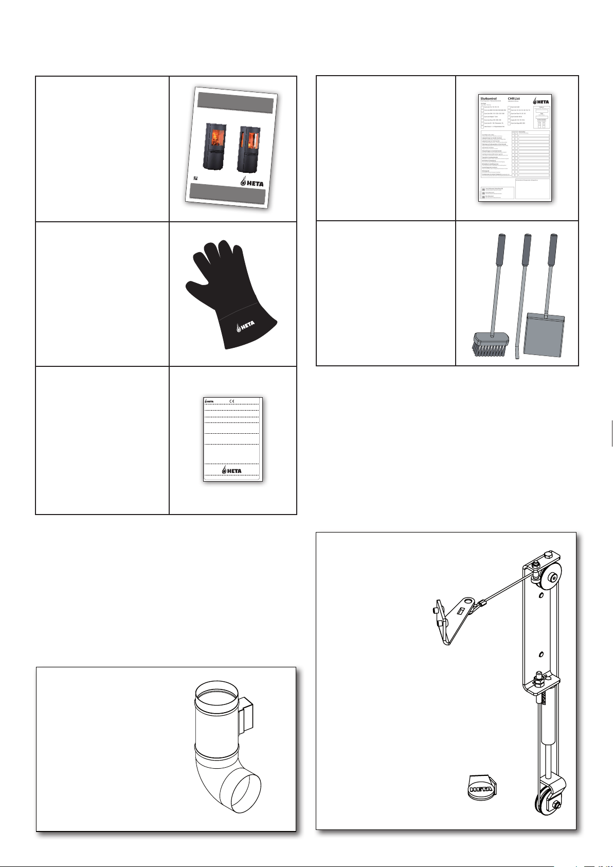
With your new wood stove you should find the following:
Operating /
Instruction manual
Heta glove
Data plate
Q.C. check
Tool set
Required tools and grease are not supplied.
Accessory
HAC kit
8057 0000-DK
Heta A/S
Jupitervej 22 . DK-7620 Lemvig . Denmark
EN 13240:2001/A2:2004 - AEA - NS 3058/3059, Aus §15A
Testrapport: 300-ELAB-2276-EN
SN No. 07-2017
Scan-Line 1000
Brændsel Træ
Ovnen er godkendt til intermitterende brug
Følg fabrikantens brugervejledning
Ovnen kan anvendes på røggassamleledning
Afstand til brændbart - bag ovn 120 mm
Afstand til brændbart - foran af ovn 1300 mm
Afstand til brændbart - side af ovn 425 mm
Afstand til brændbart - under ovn ---- mm
Nominel ydelse / rum opvarmningsudelse 7,7 kW
3
Middel CO emission i mg/Nm
960 mg/Nm3
Middel CO emission 0,077%
Røggas temperatur 204
Støv 10 mg/Nm
Virkningsgrad 86%
NOx 80 mg/Nm
OGC 76 mgC/Nm
DOP-Scan-Line 1000 2017
o
C
3
3
3
Accessory
Complete self-closing
mechanism
Nr. 6000-012419
Nr. 5032-0102
6
Page 7
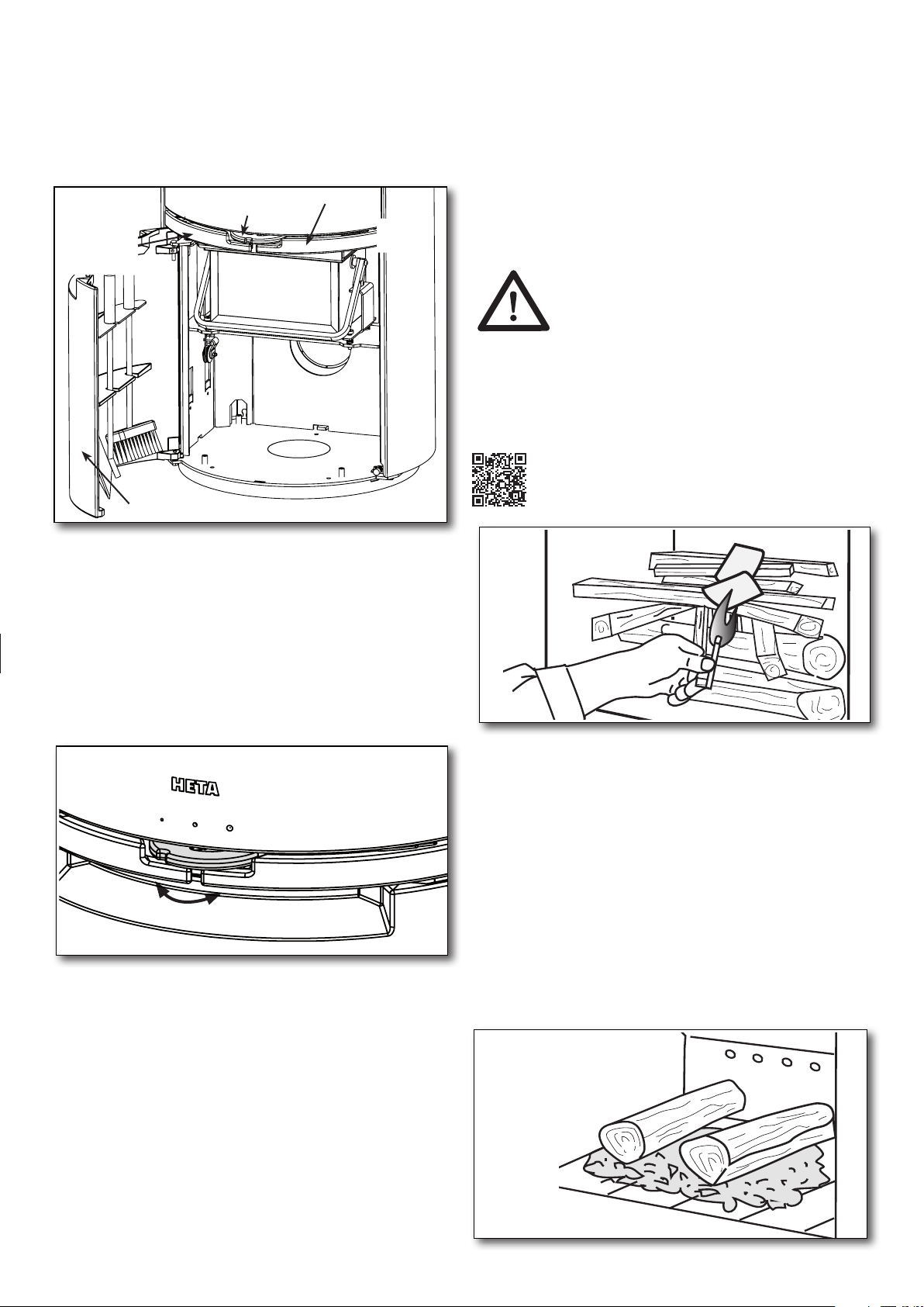
1. OPERATING INSTRUCTIONS
1.1 Before using
Before the wood stove is used make sure required
installation conditions, are met. See page 20.
1
Shaking
grate
handle
Air control
Ash pan
Lower door
Stove door
handle
1.2 First firing
1.4 Lighting the stove
Place two pieces of wood on the bottom. Stack
kindling on top in layers with air between. Set
ting fire starter (bag, brick, paraffin) on the top,
now you are ready to light the fuel. The flames
must work from the top down.
from use in a wood stove.
We recommend, all of the first fuel is burned
with the combustion air fully open in the operating position. This ensures the stove and chimney are thoroughly heated.
Startup/Lighting
Scan the code and select a language.
3
The use of lighter fluid, oils or any
liquid fuels is strictly forbidden
The stove paint is fully cured from the factory,
but a minor unpleasant odour could still arise.
1.3 Regulating the air flow
The stoves combustion air is regulated by means
of a handle below the firing door.
2
Closed
Open
Scan-Line 900 SCA stoves are designed and tested to burn extremely cleanly with very little smoke
discharge and are exempt for use in smoke control
areas throughout the UK when burning dry wood
logs. To comply, a permanent stop is fitted to
ensure that the air control slider cannot be closed beyond 24% Scan-Line 900 and 40% ScanLine 900 Sidewindows of its fully open position.
A permanent amount of air will therefore enter
the firebox to feed the fire producing negligible
amounts of smoke and unburnt hydrocarbons.
The appliances will only be considered as an
exempt appliance if this stop is in place.
See fig. 2.
1.5 Refueling
R
efueling of your stove should be done while
there is still a good layer of embers. You should
therefore air well when using the stove for the first
time.
Spread the embers over the base grate, with
most towards the front of the stove. Place firewood equivalent to 1.52 kg (Scan-Line 900)
and 1.71 kg (Scan-Line 900 Side windows) on
top of the embers in one layer, perpendicular to
the chamber opening. See fig. 4.
4
7
Page 8
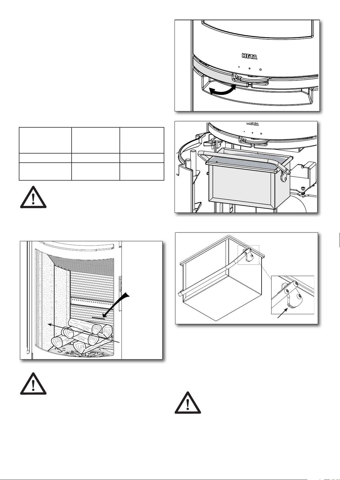
Now open the combustion air completely. If the
stove and/or chimney cools down too much, it
may be necessary to have the door ajar.
The wood will then ignite within a very short
time
(Typically 1 to 3 minutes). Once the fuel is Ignited. Close the door and regulate the air back to
operating air. When the fire is well established,
you can now regulate the operating air to the
desired combustion level.
The nominal output of 6.6 kW is equivalent to a
firing interval of approx. 50 minutes at:
6
Stove type Open combu-
stion air vent
%
Quantity of
firewood
kg.
Scan-Line 900 31 1,52
Scan-Line 900
Side windows 40 1,71
The door must be closed
during operation.
Ensure when refueling that the wood is not too
close, it will cause poorer combustion, less heat
out-put and lower efficiency.
5
Maximum
wood filling
7
Lubricate Ash pan
8
Grease not
included.
- Vermiculite
(stone)
W
hen refueling be careful to place
the fuel into the combustion chamber gently, (use the provided glove).
By not doing so you risk cracking or
breaking the vermiculite.
If there is reduced draft in the chimney, we recommend opening a window at stoking. This will
give better ventilation to the room and more oxygen for combustion.
8
2 x Grease -
1.6 Emptying the ash
By using the shaker grate, it rotates back and
forth so the ash falls through the holes and into
the ashtray, see fig. 6. It is advantageous to leave a layer of ash in the bottom of the combustion chamber on top of the grate as insulation.
Be careful when emptying the
ashes out. There can be hot
embers left for a long time.
Never empty ash into a combustible container.
Page 9

1.7 Reduced burning
The stove is, approved for intermittent use.
Never turn down the air down so much that there
does not come any flames from the tree. Wait to
close the air until the flames haveburnt out and
the tree is transformed into glowing charcoal.
If you are looking for less heat out-put, achieve
this by fueling with smaller volumes of wood and
a lower operating air. You may not completely
close the operating air during firing.
Be aware that the stove will naturally soot if the
operating air is too low. This is not good for the
environment. There is also a risk for the glass,
t
he chimney and other parts will become sooted.
By a combination of the above and possibly
burning damp wood. Can lead to high levels of
soot that it becomes sticky. Causing the sealing
of the door to tear off when opening the door
the next day.
Never use the stove if the
seals are loose.
1.8 Explosion!!!
It is very important never to leave
The stove after start up or refueling,
before the fire is established.
(Typically
Explosion hazard may be possible, if filled with
too much wood on the stove and the air supply
is to low. As large amounts of gas are being developed and this may cause a flue gas explosion.
1/2 -1
minutes)
Warning!
One must always use cation around
the stove seen, as it gets very warm
during use. (In excess of 90° C).
Children should avoid contact with the stove.
Setting up a fence if you have small children may
be necessary.
Do not place flammable objects like drying racks,
furniture, curtains too close to the stove.
when the door is open and it gives poor fuel efficiency. Leading to unnecessary polluting of the
environment.
Good draft will allow the stove to achieve optimal combustion and the highest possible efficiency. Heta wood stoves are constructed so
that it itself provides an optimal blend of combustion air. This provides a high efficiency/heat,
clean glass and low environmental impact.
Minimum chimney draft
900 and 12 PA for Scan-Line 900 Side windows.
It is the draft that the stove has been tested and
approved on. The minimum draft is necessary to
provide clean burning, beautiful flame picture,
as well as achieving the rated efficiency.
There is a risk of smoke escaping into the room
if the door is opened during vigorous firing, or if
there is a lack of air supply to the room, for ex. if
an extraction fan is in use.
Nominal fluegas temperature:
252° Scan-Line 900, r
267° S
20°C.
Scan-Line 900: Flue gas flow is: 5,0 g/sec.
Corresponding to 15 m³ / hr of combustion air
by burning 1,52 kg of wood.
Scan-Line 900 Side windows: Flue gas flow
is:
combustion air by burning 1,71 kg of wood.
The chimney height and diameter, as well as
the temperature difference between the flue gas
and outside temperature generates the chimney
draft. Chimney insulation is therefore important
as new efficient stoves create lower flue temperatures. Wind and weather conditions also influence draft, in some cases it may be disadvantageous wind direction, combined with the
position of the chimney can cause negative draft
(it blows through the chimney), causing smoke
escape from the stove.
Before using after a long period of inactivity,
check that the chimney is free for any blockages. (soot build-up, bird nests, leaves etc.).
can-Line 900 Side windows, r
5,1 g/sec. Corresponding to 15,1 m³ / hr of
: 10 PA for Scan-Line
elative to
20°C.
elative to
1.9 Draft conditions
and the chimney
Poor draft will not allow the stove to burn, as it
should. The glass can soot, requires cleaning of
the chimney more often, smoke can escape out
9
Page 10
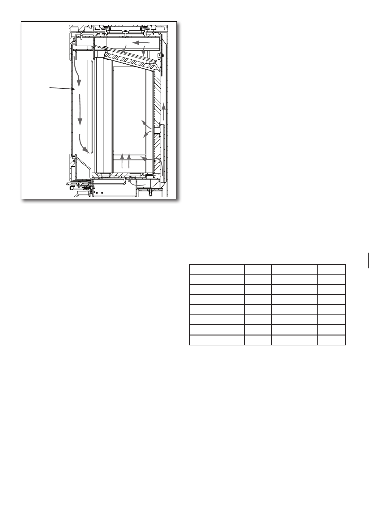
9
combustion
air
Reduced draft can occur when:
• The temperature difference is too small
between smoke gasses and outdoor
temperature, for eg. poorly insulated chimney
• To short of a chimney
• The outside temperature is high, and indoor
temperature is low for eg. in summer
• False air in the chimney
• Chimney is blocked
• Air tight house (lack of combustion air supply)
• Poorly placed chimney for the surroundings,
for ex. the ridge and trees may cause
turbulence
Good draft occurs when:
• The difference in temperature in the chimney
(warmer) and outside temperature (colder)
• It is clear weather
• The chimney has the right height min 4 meters
above the stove, and clear of the roof ridge.
1.10 Fuel
Your new stove is EN approved for firing with
wood fuel. You must therefore only burn clean,
dry wood in your stove. Never use your stove
to burn driftwood, as this may contain a lot of
salt which can damage both the stove and the
chimney. Similarly, you must not fire your stove
with refuse, painted wood, pressure-impregna-
ted wood or chipboard, as these materials can
emit poisonous fumes and smoke.
Correct firing using well seasoned wood provides optimal heat output and maximum efficiency. At the same time, correct firing prevents
environmental damage in the form of smoke
emissions and reduces the risk of chimney fires.
If the wood is damp and inadequately seasoned,
a large proportion of the energy in the fuel will be
used to vaporize the water and this will all disappear up the chimney. Thus, it is important to use
dry, well seasoned wood, for eg. wood with a
moisture content of less than 20 %. Achieve this
by storing the wood for 1–2 years before use.
Pieces of firewood with a diameter of more than
10 cm should be split before before storing. The
pieces of firewood should be of an appropriate
length (approx. 20 cm) so that they can lie
flat on the bed of embers.
If you store your wood outdoors, it is best to
cover it.
Examples of fuel values
for different woods and their typical densities
per cubic meter, specified for 100% wood with
a moisture content of 18%.
Wood kg/m3Wood kg/m
Beech 710 Willow 560
Oak 700 Alder 540
Ash 700 Scotch pine 520
Elm 690 Larch 520
Maple 660 Lime 510
Birch 620 Spruce 450
Mountain pine 600 Poplar 450
It is advised not to use oil-containing woods
like teak tree and mahogany, as this can cause damage to the glass.
3
Heating value in wood
You have to use about 2.4 kg normal wood to
replace one litre of heating oil. All woods have
almost the same heating value per kg, which is
about 5.27 kW/hour for absolute dry wood.
Wood with a moistness of 18% has a efficiency
of about 4.18 kW / hour per kg, and one litre
heating oil contains about 10 kW / hour.
10
Page 11

CO2 release
1.13 Maintenance
At combustion 1000 litres of heating oil forms
3.171 tons CO2. As wood is a CO2 neutral heat/
energy source, you save the environment about
1.3 kg CO2
mal wood.
every time you have used 1 kg nor-
1.11 Operational problems
The chimney must be swept at least once a
year, we recommend the use of a NACS (national association of chimney sweeps) registered
chimney sweep.
In the event of smoke or malodorous fumes are
being produced, you must first check to see
whether the chimney is blocked.
T
he chimney must, of course, always provide
the minimum draft necessary to ensure that it is
possible to regulate the fire. Please note, however, that chimney draft is dependent on the
weather conditions. In high winds, the draft can
become so powerful that it may be necessary to
fit a damper in the flue gas pipe to regulate the
draft.
The surface of the stove is treated with a heatresistant paint. The stove should be cleaned
with a damp cloth.
Any damage to the surface in the form of chips
or scratches can be repaired using touch-up
paint, which is available in spray can
1.14 Cleaning the glass
Incorrect firing, for example using wet wood,
can result in the viewing window becoming covered in soot. This soot can be easily and effectively removed by using proprietary stove glass
cleaner.
When cleaning the chimney, soot and other
deposits may come to fall on the baffle plate,
remove and clean it. In cases where the wood
burns too quickly, this may be due to excessive
chimney draft. You should also check to make
sure that the door seal and ash pan seal is intact and correctly fitting. If the stove it generating too little heat, this may be because you are
firing with wet wood. In this case, much of the
heating energy is used to dry the wood, resulting in poor efficiency, potentially damaging the
vermiculite and an increased risk of soot deposits in the chimney.
1.12 Chimney fire
In case of a chimney fire, which often results
from
incorrect operation/maintenance or prolonged
the air supply completely, to help slow/smother
the fire.
use of damp wood, close the door and
Call the fire department. The stove and chiminey must be inspected before use again
11
Page 12
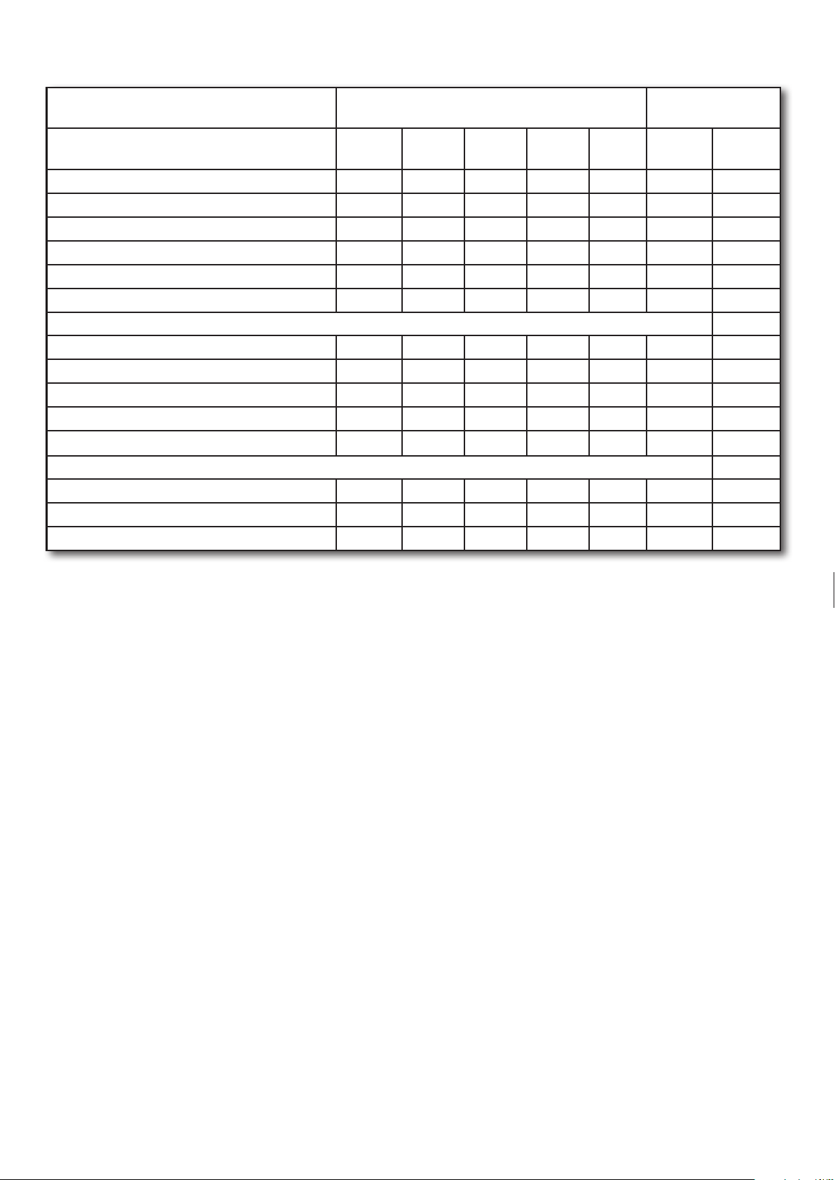
1.15 Diagram for the maintenance
Maintenance / Period
Cleaning the chimney (see. Chimney)
Cleaning the chimney and stove
Cleaning the stoves firebox
Cleaning combustion air intake
Cleaning ash bucket
Cleaning of the firebox
Checking / switch, gasket for door
Checking / changing, gasket for glass
Checking / switch, gasket for ashpan
Checking / changing gasket for flue pipe
Checking / changing vermiculite
Lubricate hinges
Lubricate lock
Lubricate Ash pan
Stove Owner
Before
Autum
Daily
1
week
30
days
60-90
days
Qualified
Technicia
1st Year 2st Year
C
C C
C VI C
C C
C VI C
C VI C
C/S VI C/S
C/S VI C/S
C/S VI C/S
C/S VI C/S
C/S VI C/S
L VI L
L VI L
L L
For the lubricant used a heat-resistant product. (300c)
C = Cleaning
C/S = Checking /Switch
L = Lubricate
VI = Visual Inspection, pos. cleaning/replacing/adjusting
12
Page 13
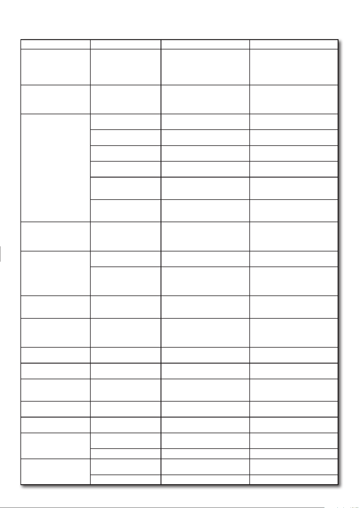
1.16 Troubleshooting table - applies to all stove types
Fault Cause Troubleshooting Solution
Lighting problems. When the
stove is cold, smoke seeps
into the room. Once the combustion chamber has heated
up, the stove burns well.
The stove burns poorly after
the warm-up phase,
glass slowly soots up.
If the stove burns poorly
after start-up, and the
glass slowly soots up.
The vermiculite in the
combustion chamber is
becoming very worn.
Too rapid combustion. Too much chimney draft. T
The vermiculite in the
combustion chamber is
cracked.
Steel surfaces in the
combustion chamber
have oxidised.
The stove whistles Too much chimney draft To test, you can open the cleaning
The stove 'clunks' Usually due to tension in the
The stove ticks Normal expansion and
The stove creaks. The temperature in the com-
The stove smells.
The surface is steaming.
Condensation in the
combustionchamber.
Condensation from the flue
pipe.
and the
Inadequate chimney draft.
The chimney only has
sufficient draft when it is hot.
Soot in the flue pipe. Check the flue pipe regularly, as the
Inadequate chimney draft.
Insufficient air supply. Check the air supply. Read the operating instructions and
Damp wood. Use clean, dry wood with a maximum
Firewood pieces too large. Optimal size – see the section for
Insufficient air supply to the
room. Range hoods, airtight
windows, etc.
Insufficient air supply to the
room. Range hoods, airtight
windows, etc
Wood and flue gases wear
down the vermiculite.
The door or ash pan/drawer
seal is defective.
Shocks or impacts while
adding firewood.
The temperature in the
combustion chamber is
too high.
metal plates.
contraction due to
temperature changes.
bustion chamber is too high.
The paint on the stove surace is not yet fully hardened.
Moisture in the vermiculite. C
Damp wood. Measure the moisture content. Use dry firewood.
The pipe is too long or the
chimney is too cold.
Damp wood Measure the moisture content. Use dry firewood.
You can test using a lighter whether
flame is drawn into the combustion
chamber.
problem arises slowly.
The fault usually already occurs during
lighting. Measure the chimney draft
moisture content of 20%.
firewood, max. diameter 10 cm.
Ensure there is sufficient fresh air
supply, open a window, check the
outdoor air supply.
Ensure there is sufficient fresh air
supply, open a window, check the
outdoor air supply.
Investigate whether the wear is
normal.
o test, you can open the cleaning
hatch, but remember to close it again.
While cold, close a piece of paper in
the door – the seal should hold the
paper gently in place so it does not
fall out by itself. Normal wear.
Normal wear Cracks only have cosmetic signifi-
Unsuitable fuel is being used (such as
coal). Check the quantity of firewood
being used, read the operating
instructions.
hatch, but remember to close it again.
Generally only occurs while heating
up and cooling down.
A normal sound. Ensure that the temperature in the
Use less firewood. Also check the seal
in the ash pan/drawer.
See the operating instructions
regarding the first firing.
heck the condition of the vermiculite.
Check the flue pipe's length and heat
loss.
Improve the chimney.
Clean regularly, and limit the use
of horizontal flue pipes. Do not use
firewood which generates large
quantities of ash.
Improve the chimney draft.
.
instruct all users.
Firewood should ideally be dried for
at least one year after splitting.
Use smaller pieces of firewood.
Depending on the cause, windows
must be opened or the outdoor air
connection cleaned.
Depending on the cause, windows
must be opened or the outdoor air
connection cleaned.
Normal wear and minor cracks are of
no significance. It should be replaced
when the steel of the combustion
chamber is visible.
Measure the chimney draft and install
a damper in the flue pipe if necessary.
Replace the seal.
cance. Replace when the steel of the
combustion chamber is visible.
If there are clear cracks or weaknesses in the stove body, it must be
replaced.
Install a damper.
Adjust the metal plates.
combustion chamber is as constant
as possible.
See the operating instructions.
Ensure there is sufficient ventilation.
Evaporates by itself after the stove has
been lit a few times.
Improve the flue pipe, insulate the
chimney.
13
Page 14
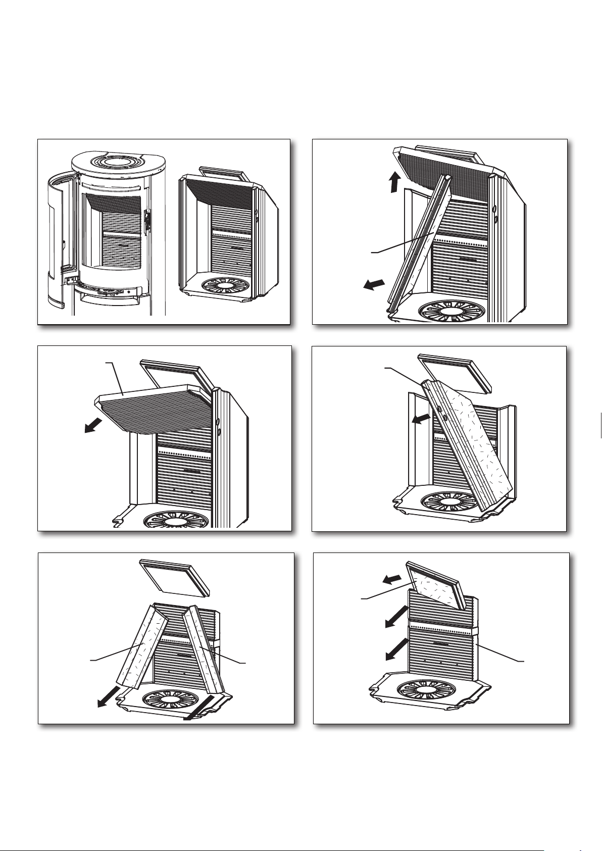
1.17 Scan-Line 900. Cleaning after sweeping
or before replacing vermiculite stones
Note: it may be necessary to clean/vaccum the holes and air ducts behind the rear stone.
Order of removing Fire bricks.
1
2
1
3
2
4
4
3
5
5
4
Replace in reverse order. Starting with Fig. 6.
4
6
5
6
14
Page 15
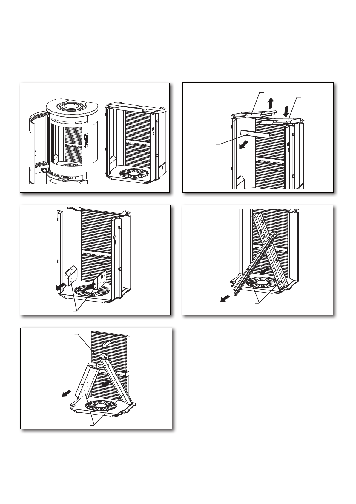
1.17 Scan-Line 900 Side windows. Cleaning after sweeping
or before replacing vermiculite stones
Note: it may be necessary to clean/vaccum the holes and air ducts behind the rear stone.
Order of removing Fire bricks.
1
2
3
2
1
3
4
5
4
5
Replace in reverse order. Starting with Fig. 5.
7
6
5
15
Page 16
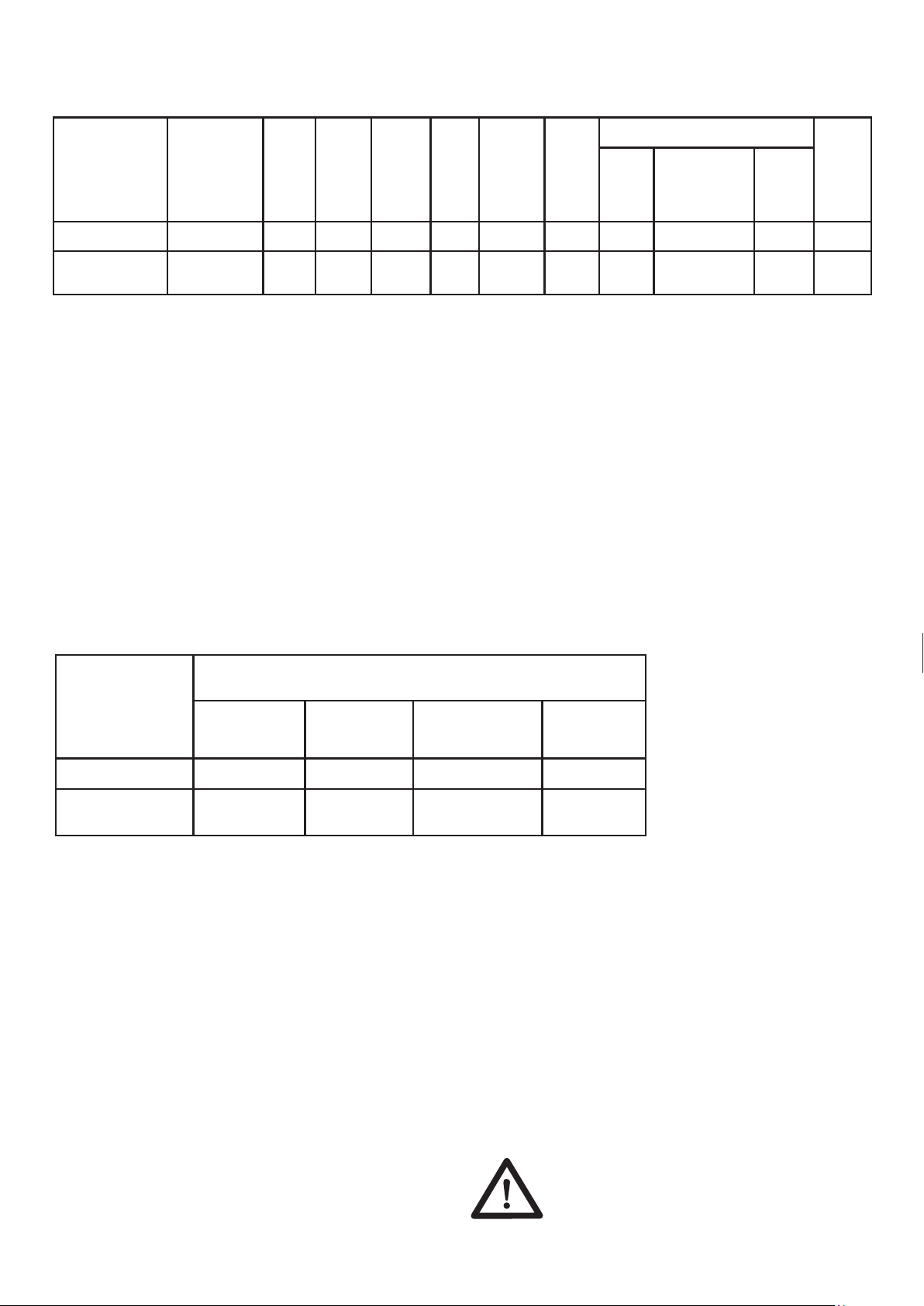
1.18 Stove data table in accordance with en 13240 testing
Tested as a freestanding oven and with uninsulated flue
Stove type Nominal
fluegas
temperature,
at 20°C room
temperature
C°
Scan-Line 900
252 ø150 ø100 1,52
Flue
mm
Air
intake
mm
Fuel
volume
kg
Draft
min.
mbar
10
Nominal
output
tested
kW
6,6 83
Actual
effi-
ciency
%
Distance to flamable materials
at the
side
mm
rear the stove
insulated/
uninsulated
flue pipe mm
350 175/175
to furnitures
mm
1000
Stove
weight
kg
*
Scan-Line 900
Side windows
267 ø150 ø100 1,71
12
6,6 81 400 125/150 900
Average temperature in the flue pipe connector:
Scan-Line 900 302° C - Scan-Line 900 Side windows 321° C
* Scan-Line 900 standard 147 kg
* Scan-Line 900 full stone 201 kg
* Scan-Line 900 stone top 155 kg
* Scan-Line 900 Side windows standard 147 kg
* Scan-Line 900 Side windows full stone 186 kg
* Scan-Line 900 Side windows stone top 156 kg
The nominal output is the output to which the stove has been tested.
Testing is conducted with the combustion air open
31% for Scan-Line 900
40% for Scan-Line 900 Side windows
Stove data table in accordance to Norwegian fire wall
Oventype
Stove
Minimum
dimensions in mm
Norwegian fire wall
Distance to fire wall with 108 mm brick.
Rear the stove
uninsulated flue
pipe
At the side
uninsulated
flue pipe
Length of fire wall
forward in front of
oven
Length of fire
wall next to
oven
*
Scan-Line 900 50 150 500 100
Scan-Line 900
Side windows
50 200 400 200
1.19 Guarantee
Heta wood stoves, subjected to a strict quality
control during production and before delivery to
the dealer.
Therefore, the stoves guarantee is
FOR FIVE YEARS
Against defects in manufacturing
- Damage caused by improper use.
- Transportation costs for warranty repair.
- Assembly / disassembly of warranty repair.
Should you have cause to make a complaint,
please quote our invoice no.
Warning
The guarantee does not cover:
Wearing parts / fragile parts such as:
- Vermiculite stones in the combustion
chamber, glass, seals and the casted bottom
or shaking grate.
Any unauthorized alterations to the
stove and the use of non-original
parts will void the warranty.
16
Page 17
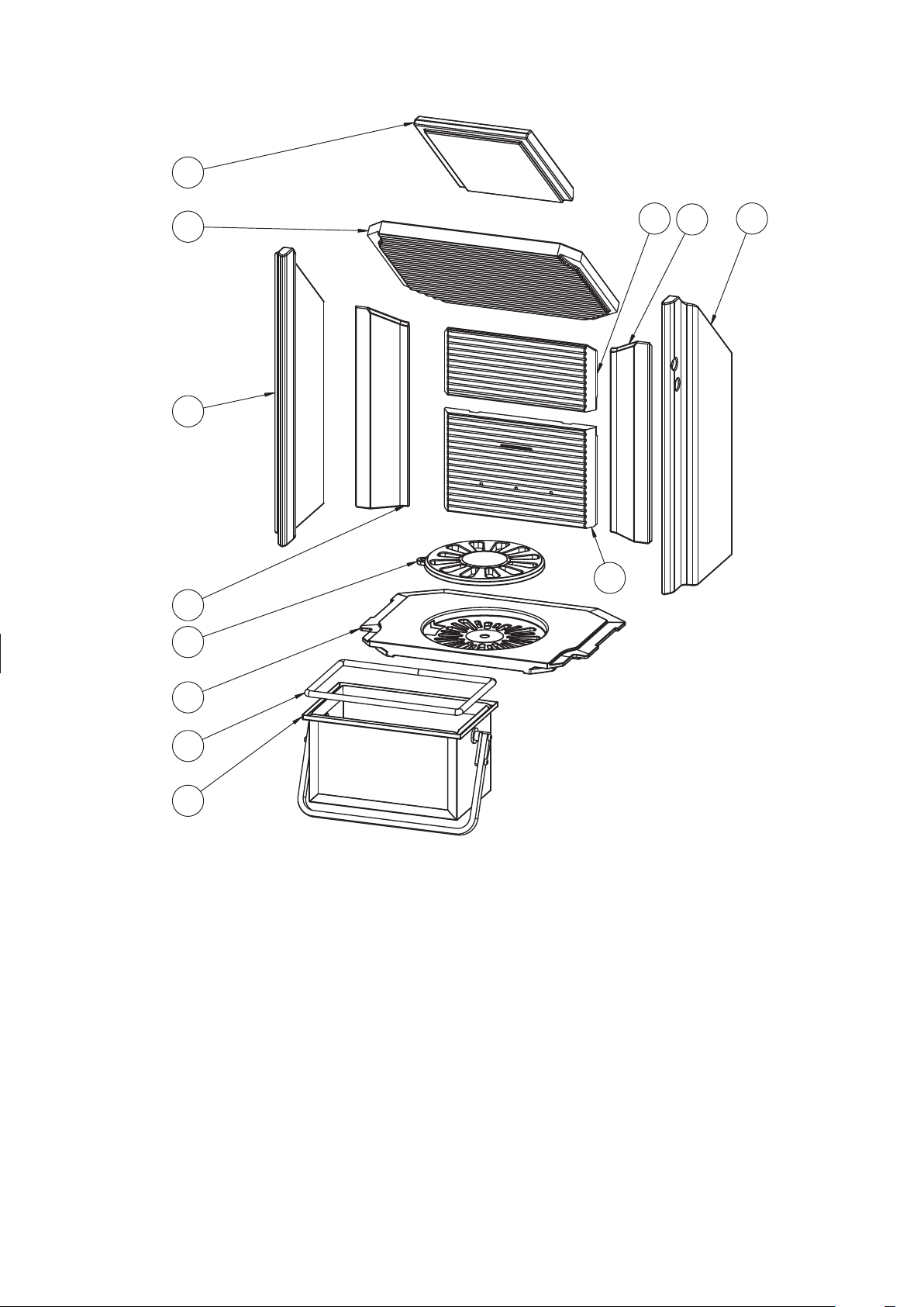
1.20 Scan-Line 900 Parts - Inside fire chamber
5
4
3
6 2
7
8
9
10
11
12
Pos. No. Name Qty.
1 0023-006028 Vermiculite, rear, bottom 1
2 0023-006261 Vermiculite, side, right 1
3 0023-006465 Vermiculite, side, left 1
4 0023-011495 Baffle 1
5 0023-012044 Baffle, small 1
6 0023-012060 Vermiculite, rear, top 1
7 0023-012061 Vermiculite, rear, right 1
8 0023-012062 Vermiculite, rear, left 1
9 0030-0201 Grate, Ø195 mm 1
10 0030-006009 Casted bottom 1
11 0023-3017 Gasket L = 850 1
12 4018-0053 Ash container 1
1
17
Page 18
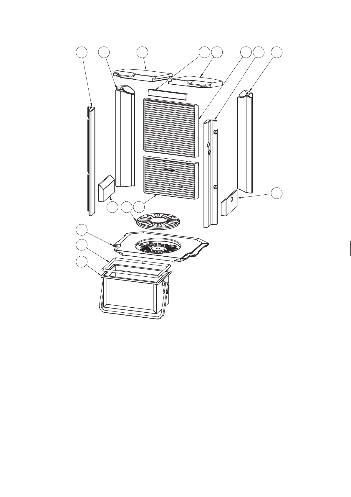
Scan-Line 900 Side windows Parts - Inside fire chamber
7
8
5
10
9
2
12
6 4
1
3
5
11
13
14
Pos. No. Name Qty.
1 0023-006026 Vermiculite, front, right 1
2 0023-006028 Vermiculite, rear, bottom 1
3 0023-006029 Vermiculite, narrow sid, right 1
4 0023-006032 Vermiculite, rear, top 1
5 0023-006050 Vermiculite, under Side windows 2
6 0023-006110 Baffle, two-part, right 1
7 0023-006467 Vermiculite, front, left 1
8 0023-012056 Vermiculite, smal side, left 1
9 0023-012057 Baffle, two-part, left 1
10 0030-0201 Grate, Ø195 mm 1
11 0030-006009 Casted bottom 1
12 1013-006262 Baffle rail 1
13 0023-3017 Gasket L = 850 1
14 4018-0053 Ash container 1
18
Page 19
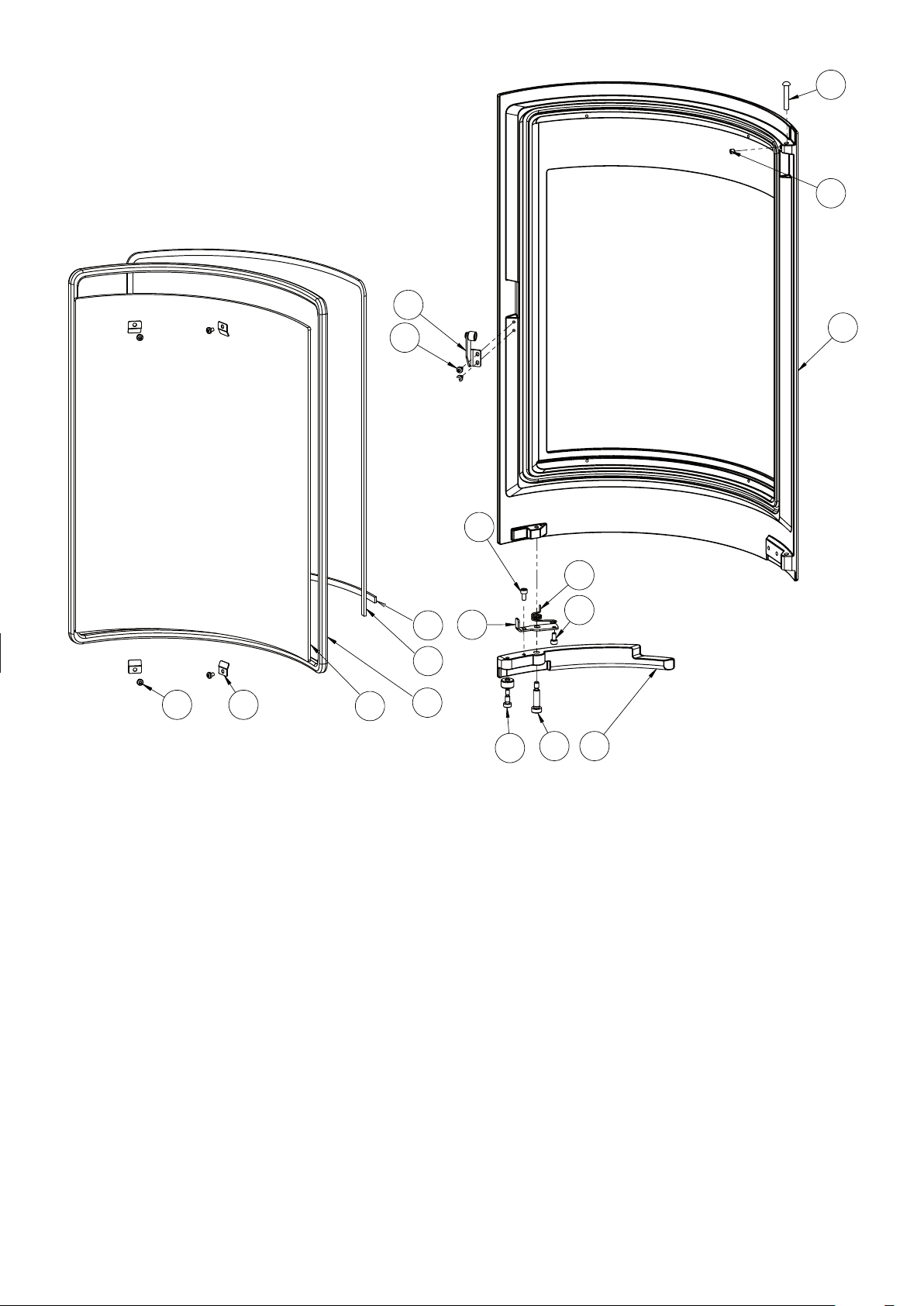
Parts - Door
7
5
2
6
14
1
16
13
12
6 17
10
11
3
Pos. No. Name Qty.
1 0008-0040 M5x10 Hexagon socket head cap 2
2 6000-005970 Close roller, completet 1
3 0008-012080 M6x10 Hexagon socket head 1
4 0008-012083 M8x25 Hexagon socket head 1
5 0008-1002 M6x6 Hexagon socket set screw 1
6 0008-2304 M4x6 Hexalobular socket pan head 6
7 0008-9082 6x35 Round head rivet 1
8 0016-007188 Spring for handle 1
9 0016-007198 Close roller 1
10 0021-006404 Glass 1
11 0023-012405 0023-3008 Glass gasket ø12 L = 1,84 m 1
12 0023-012407 0023-3010 Textile glass 6 mm
with adhesive, black L = 1,3 m 1
13 0023-012408 0023-3010 Textile glass 6 mm
with adhesive, black L = 0,36 m 1
14 0030-005956 Stove door 1
15 0030-007183 Handle 1
16 1013-007187 Bracket for door handle 1
17 1013-0432 Glass clips - small - SL 500/800 4
8
1
154
19
Page 20

Installation Instructions
Contents
2. Installation instructions ..................................................................... 21
2.1 Distance requirements ...................................................................... 21
2.2 Floor .................................................................................................. 21
2.3 Chimney connection ......................................................................... 21
2.4 Combustion air and ventilation ........................................................ 22
2.5 Stovedrawings/measurments ........................................................... 23
2.6 Connecting direct air below or behind .............................................. 24
2.7 Installing the HAC unit ....................................................................... 24
2.8 Clearances for installation EN 13 240 ............................................... 25
2.9 Changing to a back flue outlet ......................................................... 26
3. Appendix A ............................................................................................. 27
20
Remember
The stove and chimney installation, must comply with
local regulations, including those referring to national
and European standards.
Page 21
2. Installation instructions
The stove installation must be in accordance
with national, European and possibly local regulations. You must follow local regulations with
regard to installation of chimney and connection
to the chimney. We recommend that you let a
professional Heta dealer install the stove. Alternatively, you can ask the local chimney sweep
before installation. Be aware that it is always the
owner himself who has responsibility for ensuring that applicable rules are complied with.
A modern stove places heavy demands on the
chimney due to the high efficiency. It may be
necessary to enhance or even replace an old
chimney.
Remember
1. Always ensure free access to any cleaning
doors in a chimney.
2. Always ensure ample fresh air to the room.
3. Exhaust/extraction fans in the house can reduce or create negative draft in the chimney.
Reduced draft can lead to the stove having
a
dverse combustion properties. It may result
in smoke coming out of the stove when the
door is open. A negative draft due to an
exhaust/extraction fan can cause the chimney to work in reverse, drawing smoke into
the house because of the fan.
4. Any air vents must not be covered.
2.1 Distance Provisions
of the non-combustible surface must follow the
applicable national and local regulations, and
must protect against any impact from embers
that might fall out of the stove. Protecting your
floor from embers that may fall out of the oven.
Distances see data table page 16.
2.3 The chimney connection
The chimney opening must follow national and
local regulations. However, the area of the opening should never be less than 115 cm2, which
corresponds to a diameter of 121 mm. If a damper
is fitted in the flue gas pipe, there must always
be at least 20 cm2 of free passage, even when
the damper is in its “closed” position.
If local regulations permit, two contained stoves
can be connected to the same chimney. However, you must abide by local regulations regarding the distance between the two connections.
The stove must never be connected to a
chimney that is linked to a gas fire stove.
An efficient stove makes high
demand on chimney
– so always have your local
chimney sweep evaluate
your chimney.
properties
There is a difference between installation next
flammable wall or non-flammable wall. If the wall
is made of non-flammable material, the stove
principle may be placed flush against it.
We recommend a minimum of 5 cm to facilitate
air circulation around the stove.
The minimum distance to combustibles can be
found on the model plate provided with the stove or on page 16 of this manual.
to
in
2.2 Floor
You must ensure that the floor can support the
weight of the stove and a top-mounted steel
chimney.
In front of the fireplace stove, the substrate
must consist of non-combustible material, for
ex. Steel/glass plate, stone or tile floor. The size
Connection to a brick chimney
Brick a thimble into the chimney and seat the
flue gas pipe in this.
The thimble and flue gas pipe must not penetrate the chimney opening itself, but must be flush
with the inside of the chimney duct. Joins between brickwork, the thimble and flue gas pipe
m
ust be sealed with fireproof material and / or
beading
im
portance that this is done correctly with very
tight joints
that setup and installation be left to a professional Heta dealer.
. Heta A/S stresses that it is of utmost
. As mentioned earlier, we recommend
Connection to a steel chimney
When fitting a connection from a top outlet stove
21
Page 22

directly to a steel chimney, we recommend fitting the chimney tube inside the flue gas spigot
so that any soot and condensation drops into
the stove itself rather than collecting on the exterior surface of the stove. For connections to
chimneys that are run through ceilings, all national and local regulations regarding distance
to flammable material must be followed. It is important that the chimney is fitted with roof support so that the top panel of the stove is not required to bear the entire weight of the chimney
(excessive weight may damage the stove)
2.4
Combustion air and Ventilation
The stove is approved as a room air depen
stove in accordance with EN 13240. All the
combustion air in the inset stove comes from
the room in which it is fitted. However, by connecting a sealed air inlet to the stove’s air intake
connector, the stove can be supplied with external combustion air. In this respect, the following
requirements must be met:
dent
Ventilation
Adequate ventilation must be provided in accordance with building regulations (Doc J Oct
2010) especially when installing in newer build
properties when the stove is not going to be installed to an outside air supply.
The Scan-Line 900 and Scan-Line 900 Side
windows have a nominal output of less than 6,6
kW and does not need additional ventilation in
older properties where it will be ventilated by
natural leakage.
Houses built after 2008 where the air leakage
rate is less than than 5 m3 / hour / m2 then a ventilator equivalent to 550 mm2 per kW output will
be required (4.5 kW x 550 mm = 2475 mm2) unless the stove is connected to an outside fresh
air supply.
• Only approved materials may be used from
the ventilation unit to the air inlet vent.
• The air inlet vent must be tted correctly and
insulated to prevent formation of condensate.
The cross section of the vent and grille must
be at least 78 cm².
• If the vent leads out into the open air, please
note that the grille must be fitted with suitable
wind protection. There must be no risk that
the grille can get clogged by leaves, etc.
• The stove has been tested with 3 m of 100
mm pipe, with 3 90 degree bends.
22
Page 23
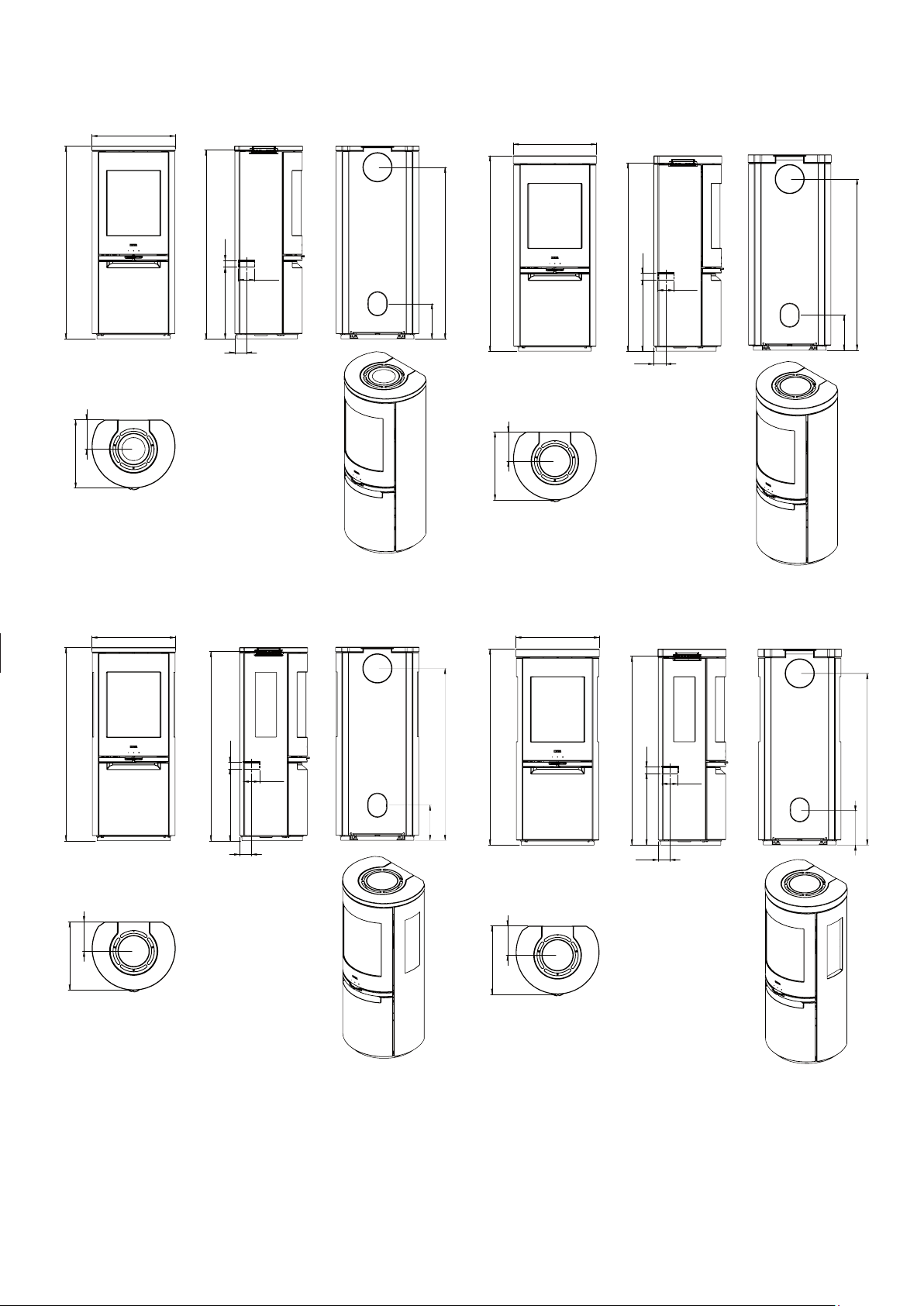
2.5 Stovedrawings/measurments
Scan-Line 900 Scan-Line 900 Stone
515
515
1191
181
421
1167
443 40
73
ø100
Scan-Line 900 Side windows
515
218
1060
1211
181
421
1167
443 40
73
ø100
Scan-Line 900 Stone Side windows
515
1060
218
1191
421
181
1167
443 40
73
ø100
218
1060
1211
421
181
1167
443 40
73
ø100
1060
218
23
Page 24
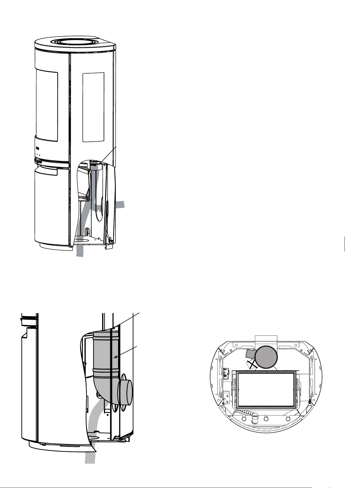
2.6 Connecting direct air below or behind
When installing external air supply, connect the
air intake to the direct air pipe using flexi-pipe,
both from the floor or behind the stove.
Flexi-pipe not included.
Air intake
ø100
Flexi pipe
back outlet
Flexi-pipe to the floor
2.7 Installing the HAC unit
Air intake
ø100
HAC KIT
5032-0102
Direct air supply
The dimensions of the direct air supply pipe,
may not be less than ø100 mm, the draught in
the flue depends on this air for optimal combustion.
Heta recommends max. 4 meters of direct air
pipe, with max. 3, 90° bends and a min. of ø100
mm.
HAC motor position.
24
Flexi-pipe to the floor
Page 25

2.8 Clearances for installation EN 13 240
A
B
D
SL 900 series
C
E
E
D
Furnitures
Combustible material
The dimensions are the
minimum dimensions,
unless otherwise stated.
150
Note your own number here _______________________
Norwegian fire wall
50 mm
108 mm brick -
insulated
-
150
300
50
- Non-flammable substrate
50
F
108
I
G
H
Clearances
Oventype
Stove
Minimum
dimensions in
mm
Scan-Line
900
Scan-Line 900
Side windows
Distance from oven to combustible material
A
Rear the stove insulated /
uninsulated
flue pipe
175/175 350 390 1000 100 50 150 500 100
125/150 400 390 900 200 50 200 400 200
B
At the
side
C
Over
oven
D
To
furnitures
E
Corner
distance
108
Norwegian fire wall
Distance to firewall with 108 mm brick
F
Rear the
stove
uninsulated
flue pipe
G
At the side
uninsulated flue
pipe
H
Length of
fire wall forward in front
of oven
I
Length
of fire
wall next
to oven
25
Page 26
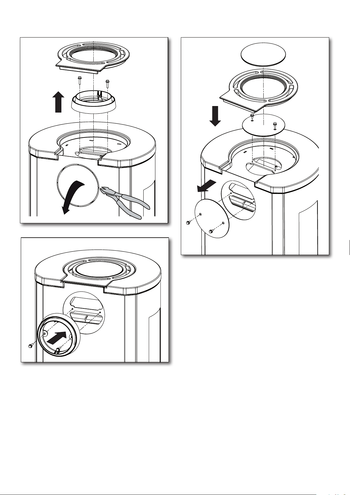
2.9 Changing to a back outlet - Steel model with casted top
1
2
3
26
Page 27

3. Appendix A
The Clean Air Act 1993 and Smoke Control Areas.
Under the Clean Air Act local authorities may
declare the whole or part of the district of the
authority to be a smoke control area. It is an offence to emit smoke from a chimney of a building, from a furnace or from any fixed boiler if
located in a designated smoke control area. It
is also an offence to acquire an” unauthorized
fuel” for use within a smoke control area unless
it is used in an” exempt” appliance (”exempted”
from the controls which generally apply in the
smoke control area).
In England appliances are exempted by publication on a list by the Secretary of State in accordance with changes made to sections 20 and
21 of the Clean Air Act 1993 by section 15 of
the Deregulation Act 2015. Similarly, in Scotland
appliances are exempted by publication on a list
by Scottish Ministers under section 50 of the Re-
gulatory Reform (Scotland) Act 2014. In Wales
and Northern Ireland these are authorized by
regulations made by Welsh Ministers and by the
Department of the Environment respectively.
Further information on the requirements of the
Clean Air Act can be found here:
https://www.gov.uk/smoke- control-area-rules
Your local authority is responsible for implementing the Clean Air Act 1993 including designation and supervision of smoke control areas
and you can contact them for details of Clean
Air Act requirements
The Scan-Line 8 with and without side windows
have all been recommended as suitable for use
in smoke control areas when burning dry wood
logs.
27
Page 28

28
 Loading...