

Page 1
1
www.heta.dk
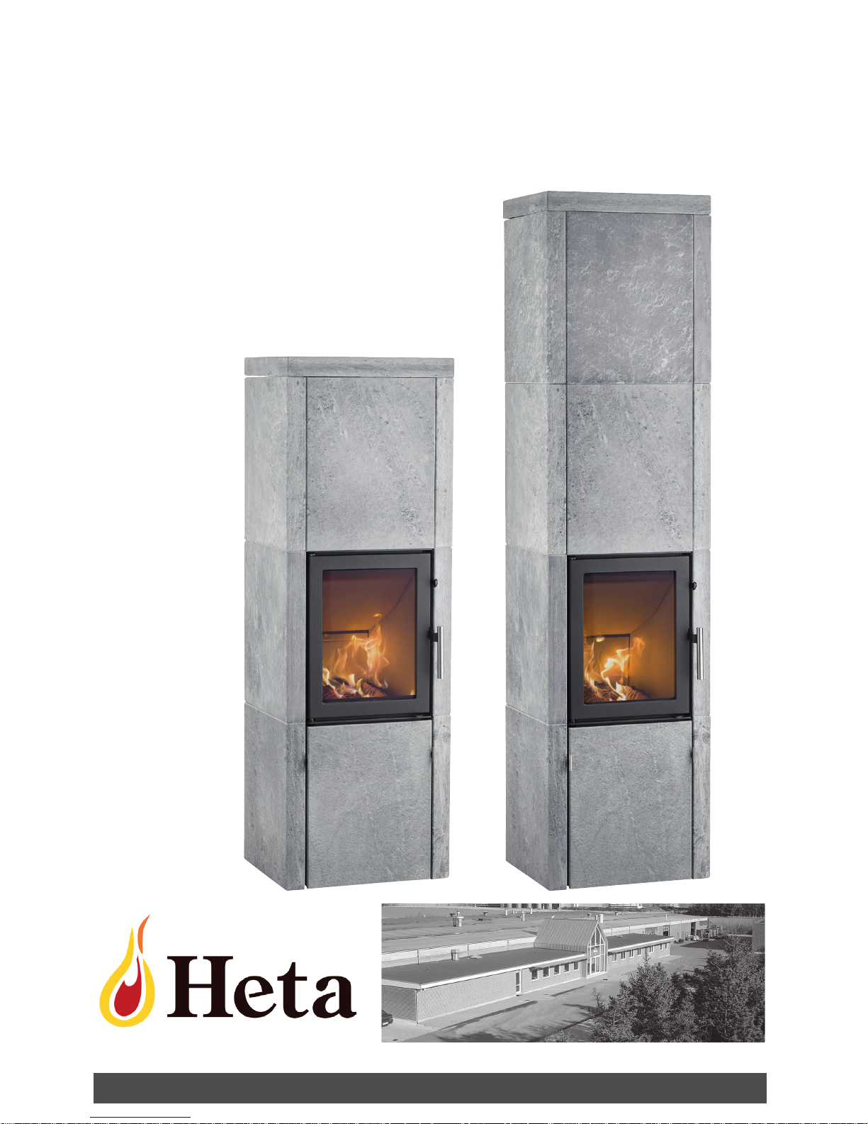
SCAN-LINE 40
SCAN-LINE 50
OPERATING INSTRUCTIONS
GB
www.heta.dk
Page 2

2
Congratulations on your new stove.
We are sure that you will be happy
with your investment, especially if you
follow the advice and instructions we
have put together in these operating
instructions.
The Scan-Line 40 and 50 have been
approved according to the EN 13240 /
NS 3058.
Approval means that consumers can
be sure, that the stove meets a range
IMPORTANT
1. Make sure there is adequate provision to sweep the chimney.
2. Make sure there is adequate ventilation to the room.
3. Please note that any extraction fans
operating in the same room as the
wood-burning stove can reduce the
chimney draft – which may have an
adverse effect on stove combustion
properties. In addition, this may
cause smoke to be emitted from the
stove
when the firing door is opened.
4. It must not be possible to cover any
air vents.
The floor
It is essential to ensure that the floor
surface can actually bear the weight
of the stove and a top-mounted steel
chimney, if applicable. The stove must
stand on a nonflammable surface such
as a steel floor plate or a brick or tile
floor. The size of the nonflammable
surface used to cover the floor area
must match national and local regulations.
The chimney connection
The chimney opening must follow
national and local regulations. However, the area of the opening should
never be less than 175 cm
2
, which cor-
responds to a diameter of 150 mm. If
of specifications and requirements
intended to ensure that the materials used are of good quality, that the
stove does not adversely affect the
environment, and hat it is economical
to use.
With your new stove you should have
received the following:
a. Operating instructions
b. A stove glove
INSTALLATION INSTRUCTIONS
Safety clearances
Stoves must always be installed in line
with national and, if applicable, local
regulations. It is important to abide
by local regulations regarding setting
up chimneys and connection to same.
Therefore, always consult your local
chimney sweep before installation, as
you are personally responsible for ensuring that the applicable regulations
have been met.
Distance regulations
A difference applies to installation
next to flammable and non-flammable
walls.
If the wall is made of non-flammable
material the stove can, in principle, be
placed flush against it. However, we
recommend leaving a gap of at least
5 cm to facilitate cleaning behind the
stove.
The minimum distances to flammable
material are stated on the boiler plate
and are listed in the table on page 6.
Warning
A stove gets hot. (In excess of
90 degrees) Take care to en
sure that children and elderly
or infirm people cannot come
into contact with it. Combustible
materials should not be stored in the
compartment below the ashpan.
Page 3

3
a damper is fitted in the flue gas pipe,
there must always be at least 20 cm
2
of
free passage, even when the damper is
in its “closed” position. If local regulations permit, two contained fireplaces
can be connected to the same chimney. However, you must abide by local
regulations regarding the distance
between the two connections.
Wood-burning stoves must never be
connected to chimneys that are also
linked to a gasfired heater. An ef-
ficient stove makes high demand on
chimney properties – so always have
your local chimney sweep evaluate
your chimney.
Connection to a brick chimney
Brick a thimble into the chimney and
seat the flue gas pipe in this. The
thimble and flue gas pipe must not
penetrate the chimney opening itself,
but must be flush with the inside
of the chimney duct. Joins between
brickwork, the thimble and flue gas
pipe must be sealed with fireproof
material and/or beading.
Connection to a steel chimney
When fitting a connection from a
top-output stove directly to a steel
chimney, we recommend fitting the
chimney tube inside the flue gas spigot so that any soot and condensation
drops into the stove itself rather than
collecting on the exterior surface of
the stove. For connections to chimneys
that are run through ceilings, all national and local regulations regarding
distance to flammable material must
be followed. It is important that the
chimney is fitted with roof support so
that the top panel of the stove is not
required to bear the entire weight of
the chimney (excessive weight may
damage the stove).
Draft conditions
Poor draft may result in smoke being
emitted from the stove when the door
is opened. The minimum chimney
draft to ensure satisfactory combu-
stion in stoves of this kind is 12 PA.
However, there will still be a risk of
smoke emission if the firing door is
opened during powerful firing. The
flue gas temperature at nominal
output is 257°C when expelled to an
exterior temperature of 20°C. The flue
gas mass flow is 6 g/sec. The chimney
draft is generated by the difference
between the high temperature of the
chimney and the low temperature of
the fresh air. The length and insulation
of the chimney, wind and weather
conditions also have an effect on the
ability of the chimney to generate appropriate under-pressure.
If the stove has not been used in a
while, check that the chimney and
stove are not blocked with soot, bird
nests, etc., before using it.
Reduced draft can occur when:
• The difference in temperature
is too small - due to insufficient
chimney insulation, for example.
• The outdoor temperature is too
high in summer, for example.
• No wind is blowing.
• The chimney is too low and sheltered.
• The chimney contains false air.
• The chimney and flue gas pipe are
blocked.
• The house is too airtight (i.e. when
there is an insufficient supply of
fresh air).
• Poor smoke extraction (poor draft
conditions) due to a cold chimney
or bad weather conditions can be
compensated for by increasing the
airflow into the stove.
Good draft occurs when:
• The difference in temperature
between the chimney and outdoor
air is high.
• The weather is fine.
• The wind is blowing strongly.
• The chimney is of the correct
height: at least 4.00 m above the
stove and free of the roof ridge.
Page 4
4
storing. The pieces of firewood should
be of an appropriate length (approx.
25–30 cm) so that they can lie flat on
the bed of embers. If you store your
wood outdoors, it is best to cover it.
Examples of fuel values of
different woods
Fuel type / number of cubic metres per
1,000 litres of oil
Oak Beech Ash Birch Elm Common
spruce
7.0 7.0 7.2 8.0 8.9 10.4
Chimney fires
In the event of a chimney fire – which
often results from incorrect operation
or protracted firing with moist wood
– close the door and shut off the secondary/start-up air supply to smother
the fire. Call the fire department.
Lighting and combustion
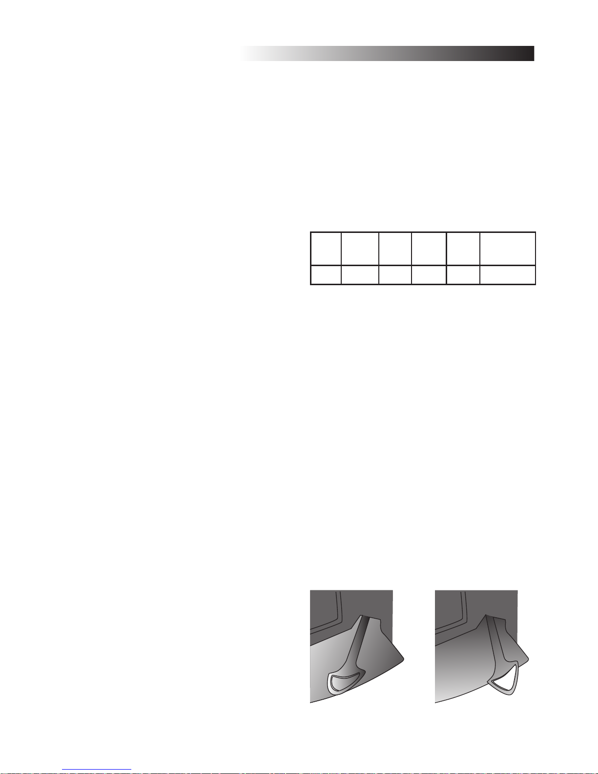
To open the flow of secondary air, use
the operating handle at the front of
the stove. The secondary airflow is
completely open when the handle is
to the left side position, fig. 1.
Shut off the secondary airflow gradually by moving the handle to the
right. The supply is completely shut off
when the handle is to the right side
position, fig. 2.
INSTRUCTIONS FOR USE
Open Closed
Fig. 1 Fig. 2
First firing
The stove has been treated with a
heat-resistant coating which hardens
at a temperature of approximately
250 ºC.
This hardening process causes the
production of smoke and malodorous
fumes, so the room must be very well
ventilated.
During the first firing, which should
be carried out using approximatly 1,0
kg. of wood, the stoking door must
be left slightly open and must not be
closed until the stove is cold. This is to
prevent the sealing rope sticking to
the stove.
Fuel
Your new stove is EN approved for
firing with wood fuel. You must
therefore only burn clean, dry wood
in your stove. Never use your stove to
burn drifwood, as this may contain a
lot of salt which can damage both the
stove and the chimney. Similarly, you
must not fire your stove with refuse,
painted wood, pressure-impregnated
wood or chipboard, as these materials
can emit poisonous fumes and smoke.
Correct firing using well seasoned
wood provides optimal heat output
and maximum economy. At the same
time, correct firing prevents environmental damage in the form of smoke
and emmissions and also reduces the
risk of chimney fires. If the wood is
wet and inadequately seasoned, a
large proportion of the energy in the
fuel will be used to vaporise the water,
and this will all disappear up the chimney. Thus it is important to use dry,
well seasoned wood, i.e. wood with
a moisture content of no more than
18%. This is achieved by storing the
wood for 1–2 years before use. Pieces
of firewood with a diameter of more
than 10 cm should be split before
Page 5
5
Lighting
To ignite the fuel, use fire lighters,
small paraffin ignition bags or small
pieces of wood placed on the bottom
grate. Place larger pieces of wood on
top of this kindling material, at right
angles to the firing, doors. Completely open the secondary air supply and
leave the firing door ajar – i.e. approx.
1 cm open. Once the fire has taken a
good hold of the fuel and the chimney
has heated up (after about 10 min)
close the firing door. We recommend
that you burn the entire first firing
with the secondary air supply fully
open to make sure that the chimney is
thoroughly heated.
Refiring
You should normally refire the stove
while there is still a good layer of
embers. Distribute the embers across
the bottom grate, place pieces of
fuel (max. 2 kg) on the embers in a
single layer perpendicular to the firing
opening. Close the firing door and
fully open the start-up mechanism.
The wood will then ignite very quickly
– i.e. in 30 seconds or 1 minute. When
the wood is burning with a steady
flame, close the start-up mechanism.
Then adjust the secondary airflow to
the level required. For nominal operation (5 kW), the secondary air supply
should be 70% open. When firing,
take care not to place the pieces of
fuel too close-ly together, as this will
result in poor combustion and insufficient exploitation of the fuel.
Reduced burning
The stove is well-suited to intermittent use. If you wish to operate the
stove with reduced out-put, simply
insert smaller volumes of wood at
each firing, and apply a lower airflow.
However, remember that the secondary combustion air supply must never
be shut off completely during firing.
It is important to keep a good bed of
embers. Gentle heat is released when
the fire settles - i.e. when the wood no
longer generates flames and has been
converted to glowing embers.
Optimal firing
To achieve optimal firing and the
highest possible effect, it is important
to make sure that the air supply is
used correctly. As a general rule, the
secondary air is to be used to control
the fire to ignite the flue gases. This
produces a high effect and keeps the
glass panel completely clear of soot
as the secondary air “washes” down
over it. Please note that the stove will,
naturally, produce soot if both the
start-up mechanism and secondary
air intakes are closed completely.
This will prevent oxygen from being
drawn into the stove, and the viewing
window and other parts will become
covered with soot. If this situation is
combined with firing with wet wood,
the build-up of soot can become so
thick and sticky that the sealing rope
can, for example, become detached
when the door is opened the next day.
Risk of explosion
After you add new fuel, it is
very important that you do
not leave the stove unatten
ded until the wood is burning
constantly. This will normally occur
within 30 to 60 seconds.
A risk of explosion can possibly arise if
too much wood is placed in the stove.
This may result in the production of
large volumes of gas, and this gas can
explode if the intake of primary and
secondary air is insufficient.
It is an advantage always to leave
some ash lying in the bottom of the
combstion chamber.
Take care when emptying the ash pan,
as cinders can continue to burn in the
ash for long periods of time.
Page 6

6
Stove data table in accordance with EN 13240 testing.
Stove
type
Scan-Line
series
Nominal
uegas
temperature c°
Smoke
stub
mm
Fuel
volume
kg
Draught
min
mbar
Nominal
output
tested
kW
Heat
output
kW
Distance to flammable
materials in mm
behind at the
the stove sides
Distance to
furnitures from
the stove in
mm
Stove
weight
kg
40 257
ø150
1.6
0.12
5 5 150 400 900
420
50 257
ø150
1.6
0.12
5 5 150 400 900
541
The nominal output is the output to which the stove has been tested.
The test was carried out with the secondary air 70% open.
The chimney must be swept at least
once a year, we recommend the use
of a NACS (national association of
chimney sweeps) registered chimney sweep. In the event of smoke or
malodorous fumes being produced,
you must first check to see whether
the chimney is blocked. The chimney
must, of course, always provide the
minimum draught necessary to ensure
that it is possible to regulate the fire.
Please note, however, that chimney
draft is dependent on the weather
conditions. In high winds, the draft
can become so powerful that it may
be necessary to fit a damper in the
The surface of the stove has been treated with heat-resistant paint.
The stove should be cleaned with a
damp cloth. Any damage to the surface in the form of chips or scratches
can be repaired using touch-up paint,
which is available in spray cans.
Cleaning the glass
Incorrect firing, for example using
wet wood, can result in the viewing
window becoming covered in soot.
This soot can be easily and effectively
removed by using proprietary stove
glass cleaner.
flue gas pipe to regulate the draft.
When cleaning the chimney, soot and
other deposits may come to fall on the
smoke plate. In cases where the wood
burns too quickly, this may be due
to excessive chimney draught. You
should also check to make sure that
the door seal and ashpan seal is intact
and correctly fitting.
If the stove it generating too little
heat, this may be because you are firing with wet wood. In this case, much
of the heating energy is used to dry
the wood, resulting in poor heating
economics and an increased risk of
soot deposits in the chimney.
OPERATIONAL PROBLEMS
MAINTENANCE
Page 7
7
GUARANTEE
The model Scan-Line 500 stoves are
subjected to stringent quality control procedures both throughout the
produc-tion process and immediately
before delivery to the dealer. Therefore, the stoves are guaranteed against
defects in manufacturing
FOR FIVE YEARS.
This guarantee does not cover: Wearing parts/fragile parts such as:
• The fire-proof bricks in the combustion chamber.
• The smoke baffle • The glass
• The sealing rope • The grate frame
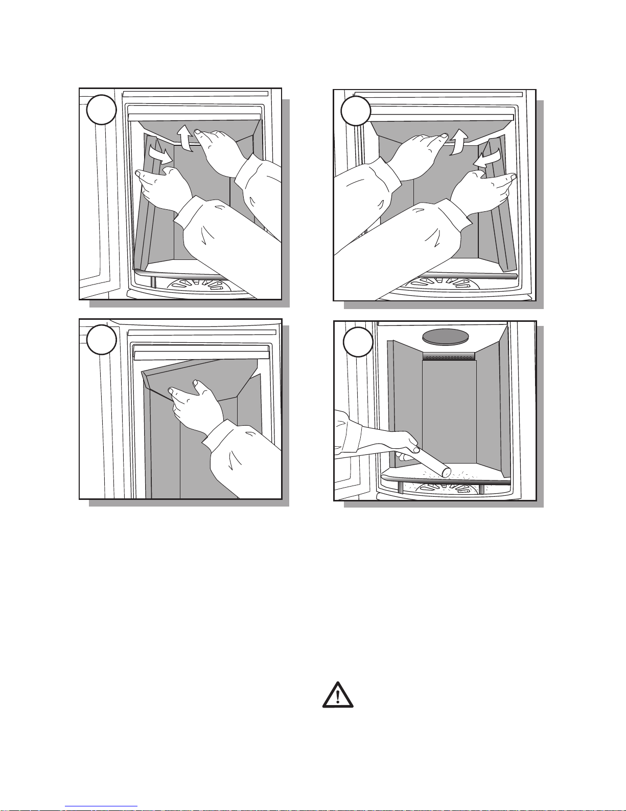
Cleaning after sweeping the chimney and
replacing the stones. Fig 3-6
3
4
5
6
Damage resulting from incorrect use
Transport costs in connection with
repairs carried out under guarantee
Installation/disassembly in connection
with repairs carried out under guarantee. Should you have cause to make
a complaint, please quote our invoice
no.
Warning
Any unauthorised modification
of the stove and any use of
non-original spares will void
the guarantee.
Page 8
8
Fronten af ovnen
Fronten af ovnen
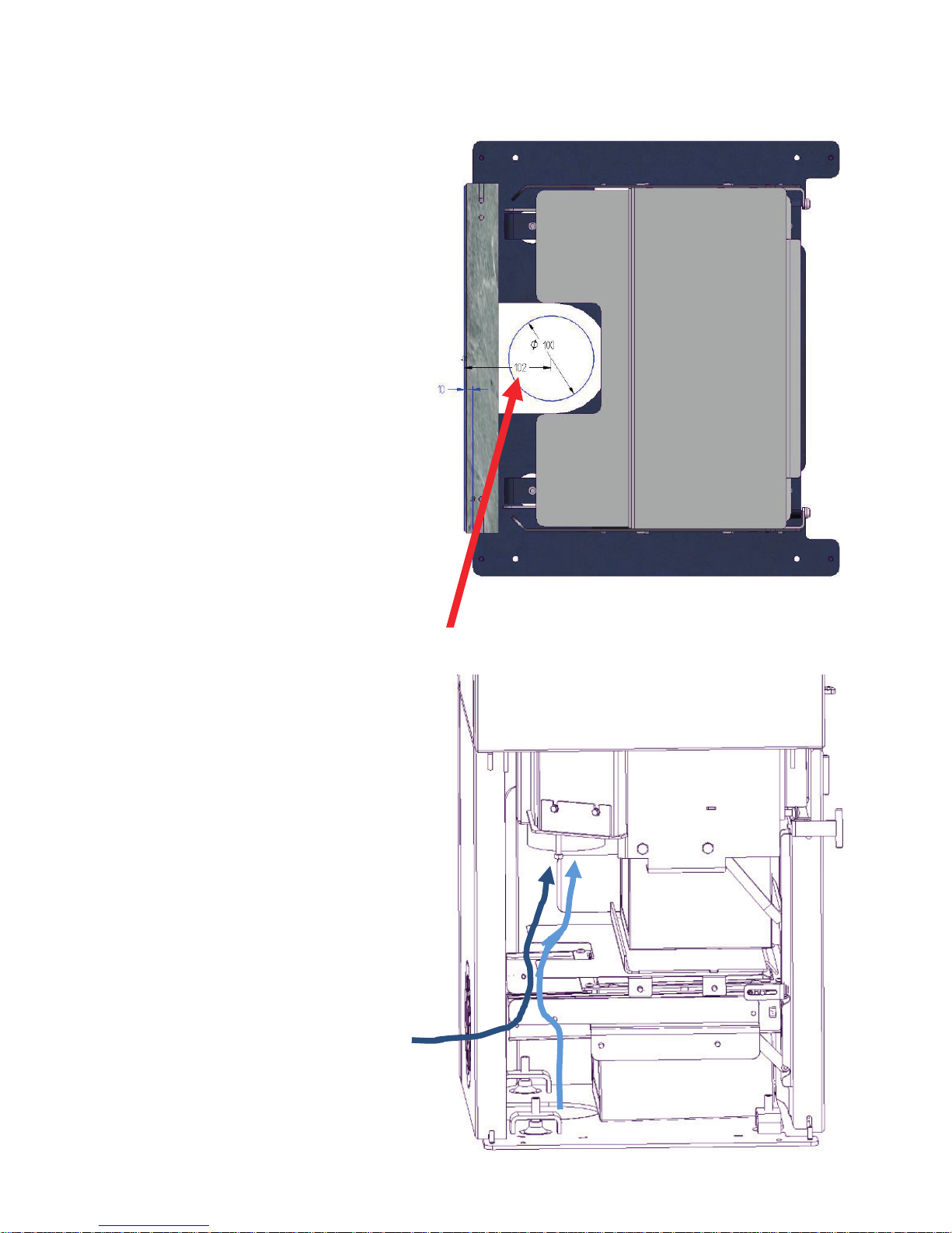
CONNECTION OF EXTERNAL AIR FLOW
(FRESH AIR)
There is 102 cm from the outside of rear soapstone to the
center of the hole for the external air flow connection through
the floor. The pipe must fit a
flexible ø100 mm hose.
The external air can be supplied
to the stove both from below by
removing the pre cut bottom or
through the air intake hole in
the bottom stone.
It is recommended to use an
ø100 mm alu flex hose that can
withstand temperatures up to
200°.
The flexible hose is not included, but can be purchased
separately.
Page 9
9
INSTALLATION INSTRUCTIONS
Scan-Line 40 and 50
Please read carefully before installing
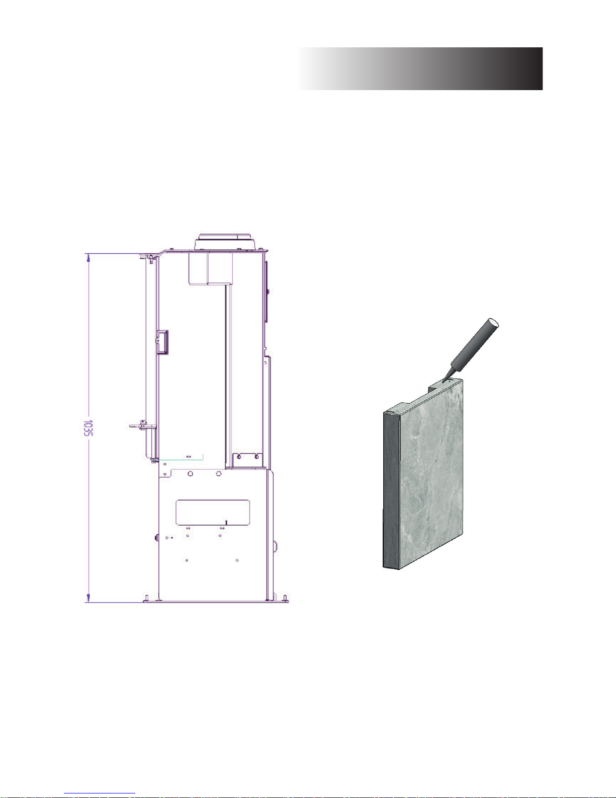
the stove. NB! Before assembling the
soapstones, ensure that the underlay/
floor is level and that the distance
from the floor to the top plate is 1030
mm. The stove must be in level. To adjust, turn the adjusting screws on the
base up/down.
We recommend installation of the
soapstones is carried out by two
people.
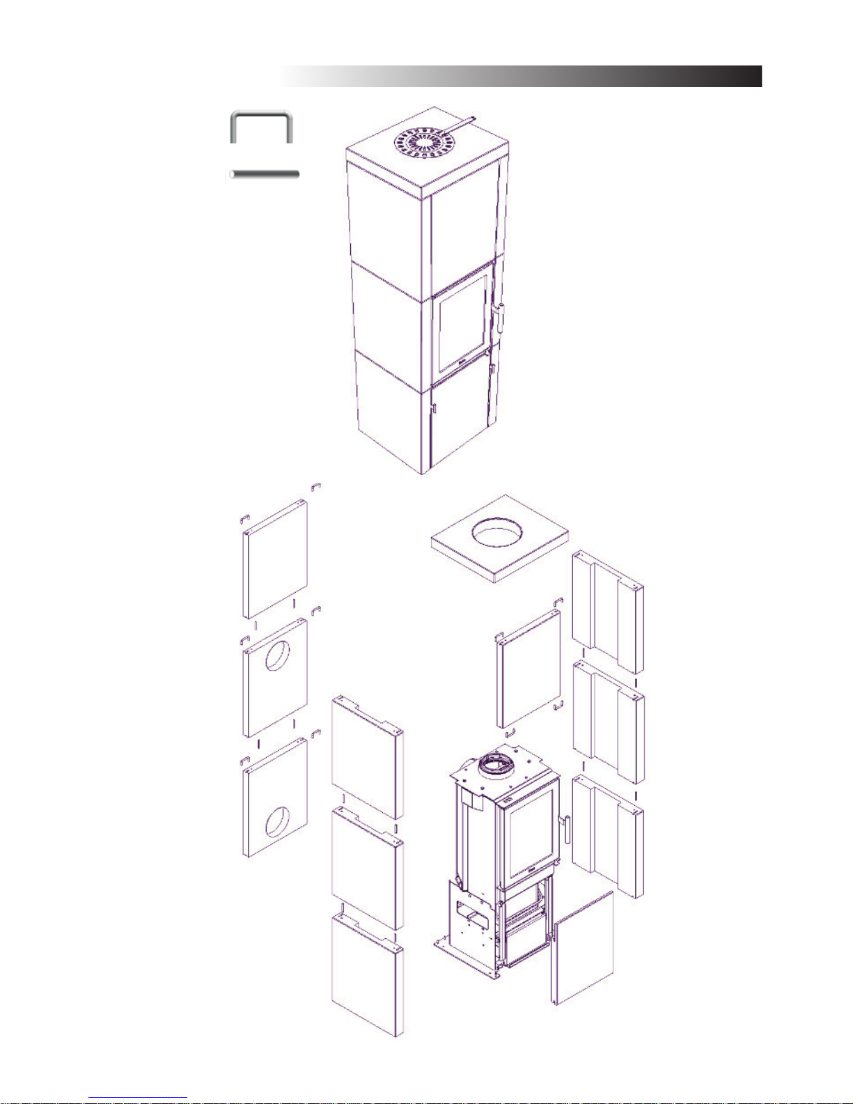
A standard set of brackets and pins
are provided for installation of the
soapstones. Refer to the overview
on page 10 and 20 to see how many
brackets/pins are required.
If required, lubricate the pin holes
with a small amount of silicon. Can
also be applied between the stones.
Fig. 1
Page 10
10
16 x standard
brackets
12 x standard
pins
SCAN-LINE 40
Scan-Line 40
Page 11
11
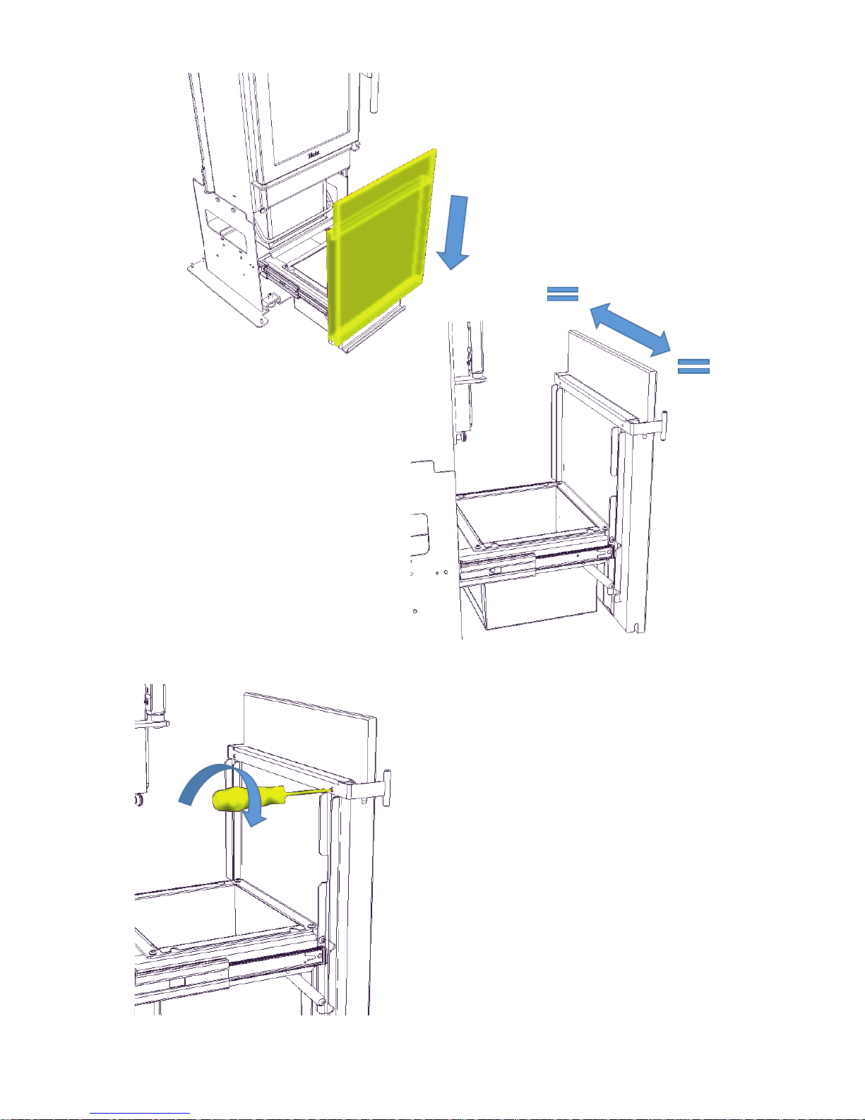
Place the stone into the groove
on the door so that it is equidistant to both sides. Important!
The stone must be manually
held in place until the handle is
fitted.
Fig. 2
The handle is fitted by placing it
into the groove in the stone and the
ash pan frame. Adjust the handle so
that is it placed in the middle of the
ash pan frame.
Tighten the handle with the supplied
two M5x6 screws.
Scan-Line 40
Page 12
12
Fig. 3
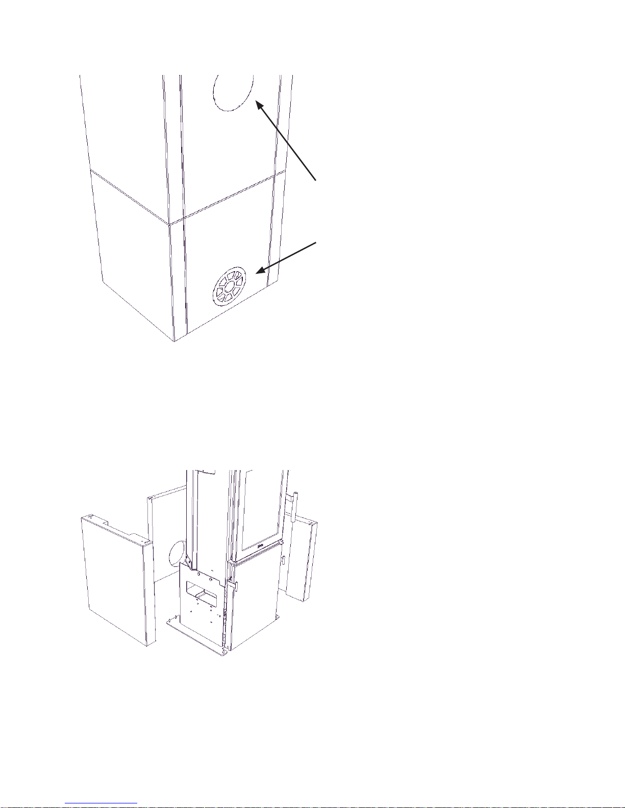
NB: Behind the stove, the stone with
hole for convection, must be placed at
the bottom. The next stone with hole
is put on top if there is smoke outlet
behind. Fig. 3
The closed cover should be placed
here unless the stove should be
mounted with back outlet
The open cover should be placed here.
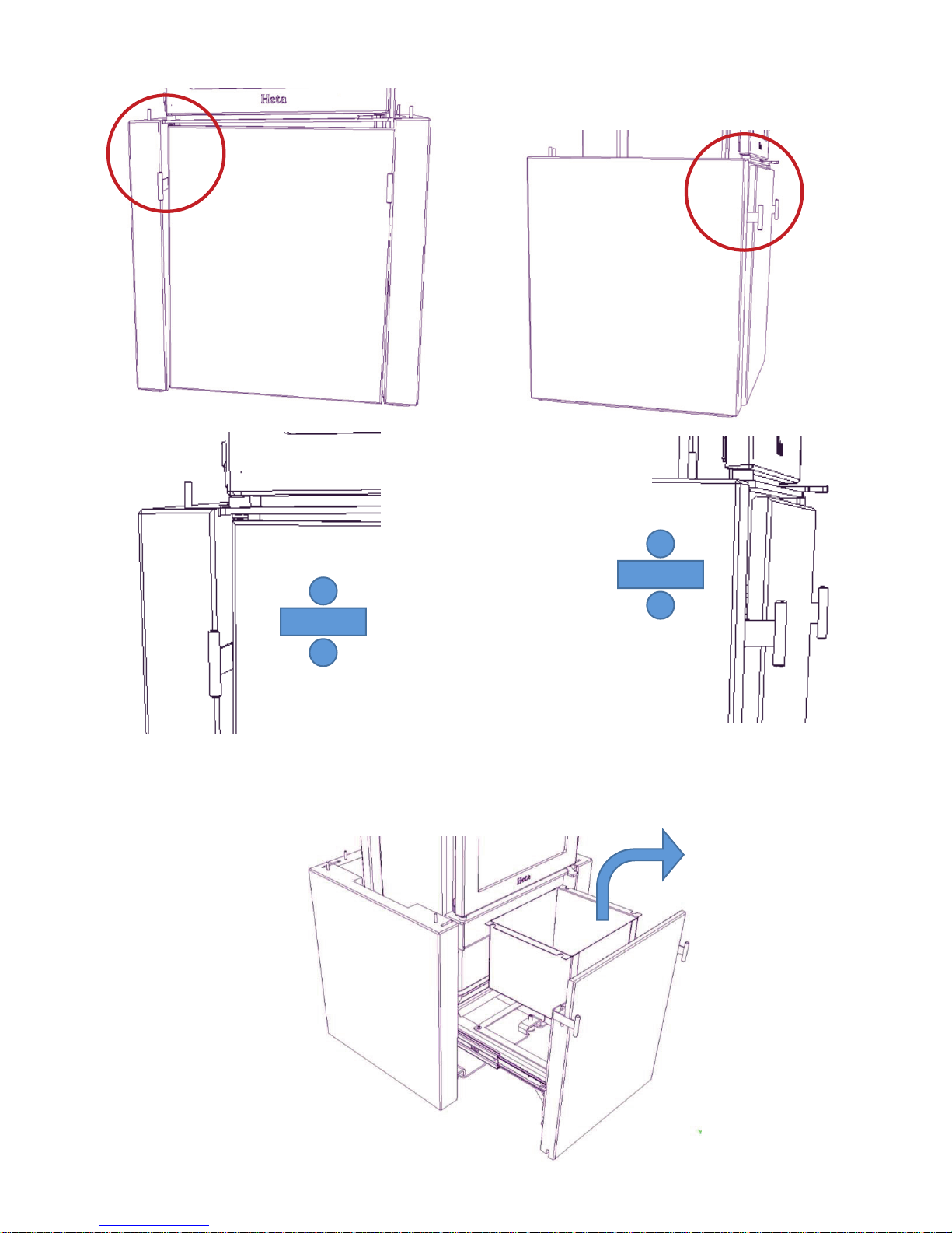
Continue with sidestones as shown
i fig. 4. and place Brackets under.
Then place the backstone with
hole for convection and finish the
first round with af sidestone.
Fig. 4
Scan-Line 40
Page 13
13
Scan-Line 40
Page 14
14
Scan-Line 40
Page 15
15
Scan-Line 40
Page 16
16
Scan-Line 40
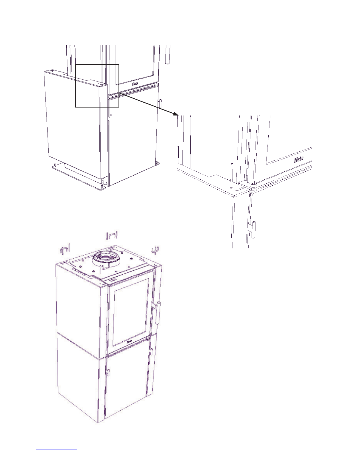
Fig. 5
Put brackets and pins in as shown. fig.
5.
Continuing with the next row. Start
with sidestone, backstone and then
sidestone again. Place brackets and
pins. fig. 6
Page 17
17
Scan-Line 40
THERMASTONES
Step 1 Step 2 Step 4Step 3
Optional thermastones are also available. Three thermastones can be installed in this stove.
The thermastones must be added after
the soapstones have been placed and
the stove/firebox has been adjusted.
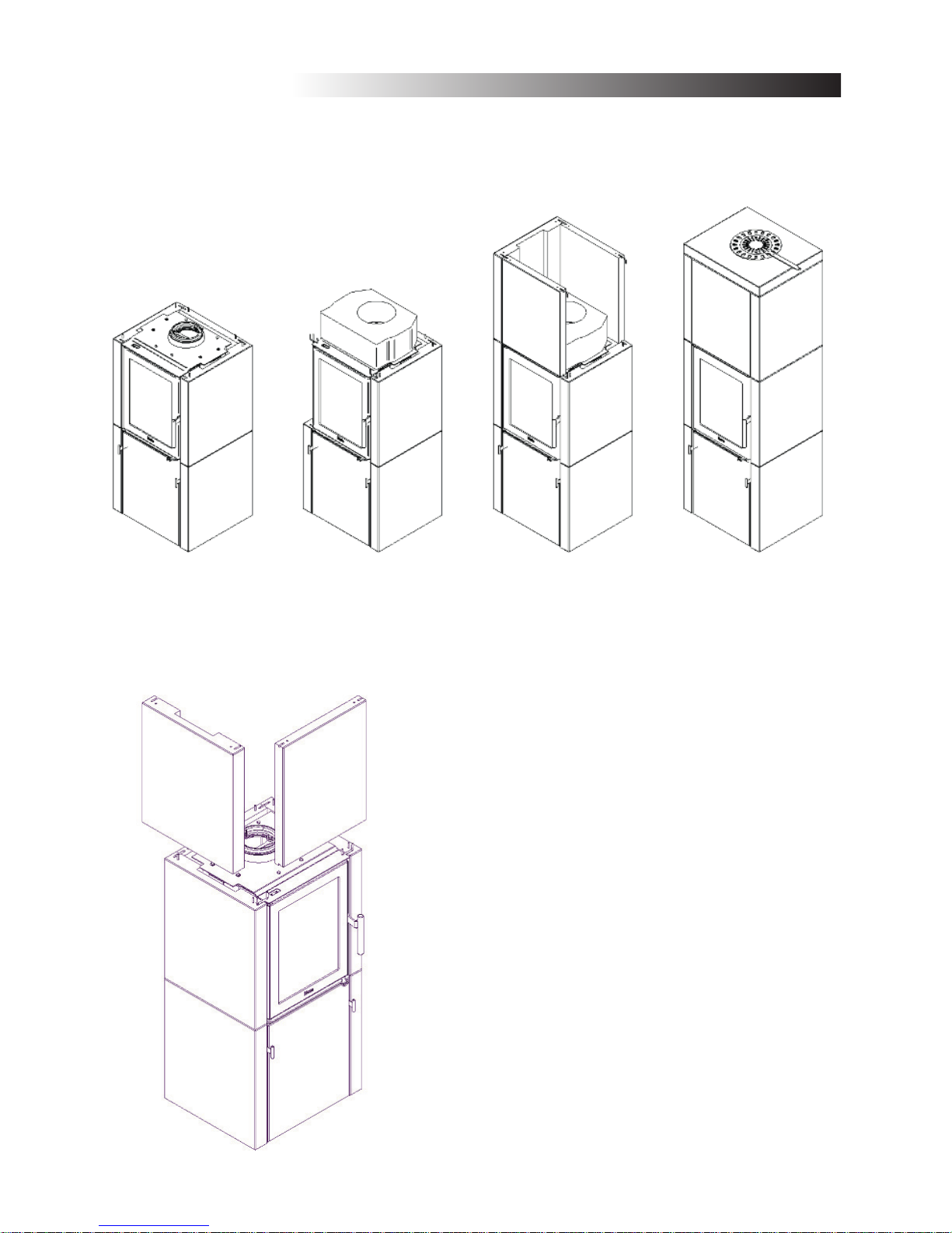
Fig. 7
Continue with the 3. row. Start with
the front stone with the two brackets
beneath (resting on the metal frame)
and then a side stone, which should be
placed on the pins/brackets. fig. 7
Page 18
18
Scan-Line 40
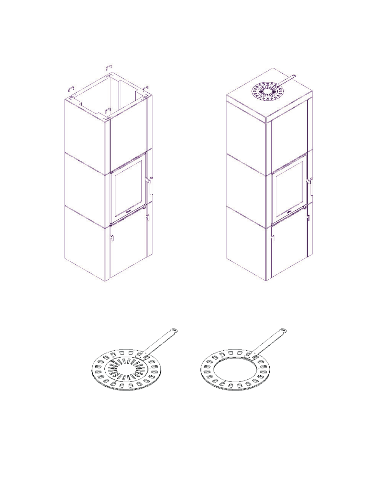
Fig. 8
Fig. 9
Continue with the back stone and
then the last side stone. Place brackets
on top. No pins are nessesary Fig. 8
Finish with the topstone - placein it
loose on top. If the stove has a top
flue, break of the inner ring. Fig. 9
Top flue - break of the inner ring.
Page 19
19
Scan-Line 40
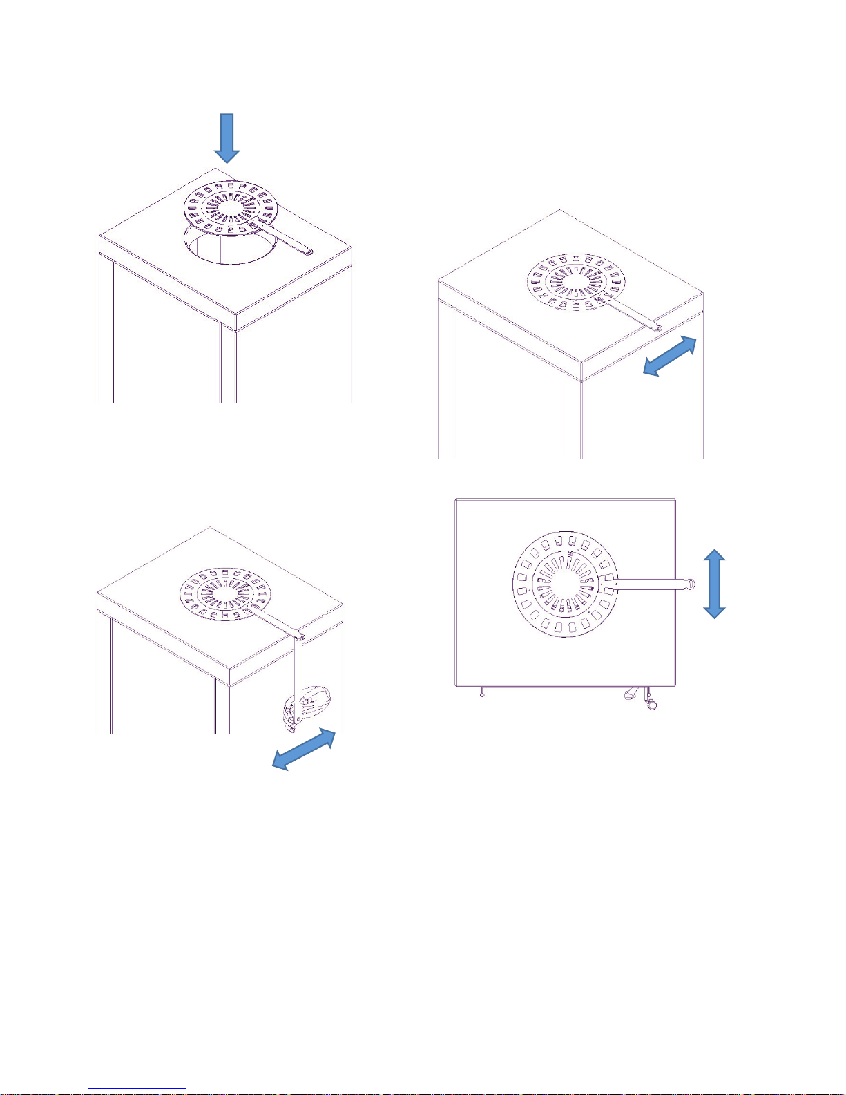
Open
Closed
Regulate the convection air flow by turning the handle on the side of the stove.
Page 20
20
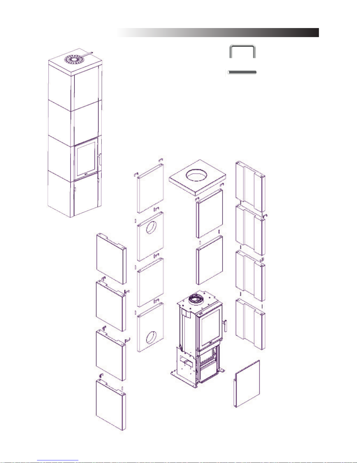
SCAN-LINE 50
20 standard
brackets
20 standard
pins
Scan-Line 50
Page 21
21
Scan-Line 50
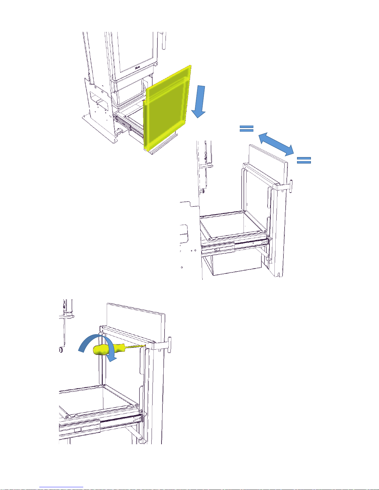
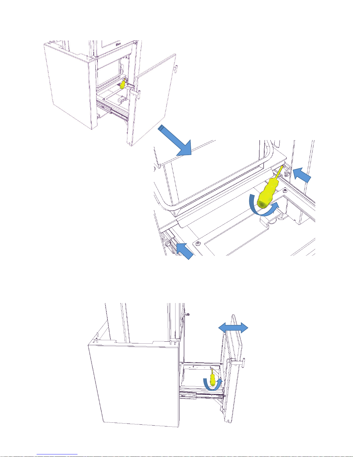
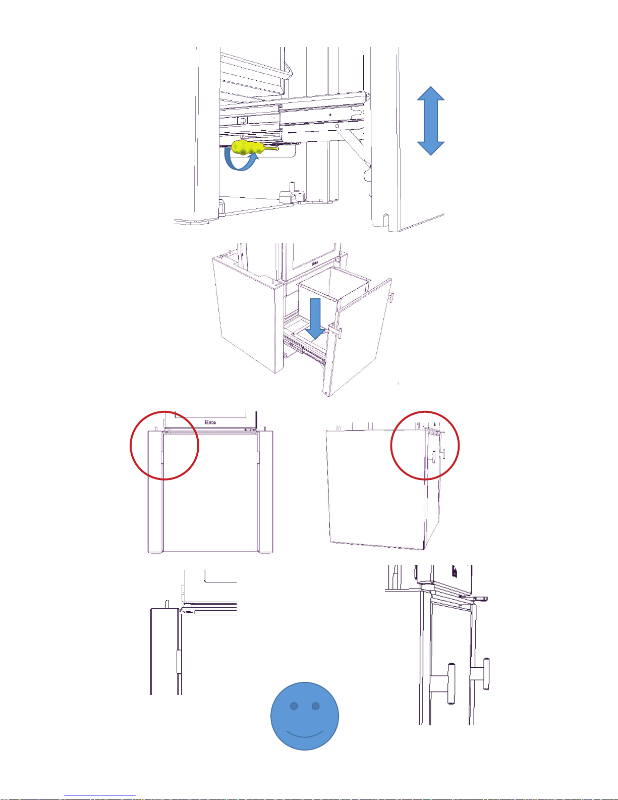
Place the stone into the groove
on the door so that it is equidistant to both sides. Important!
The stone must be manually
held in place until the handle is
fitted.
Fig. 2
The handle is fitted by placing it
into the groove in the stone and the
ash pan frame. Adjust the handle so
that is it placed in the middle of the
ash pan frame.
Tighten the handle with the supplied
two M5x6 screws.
Page 22
22
Scan-Line 50
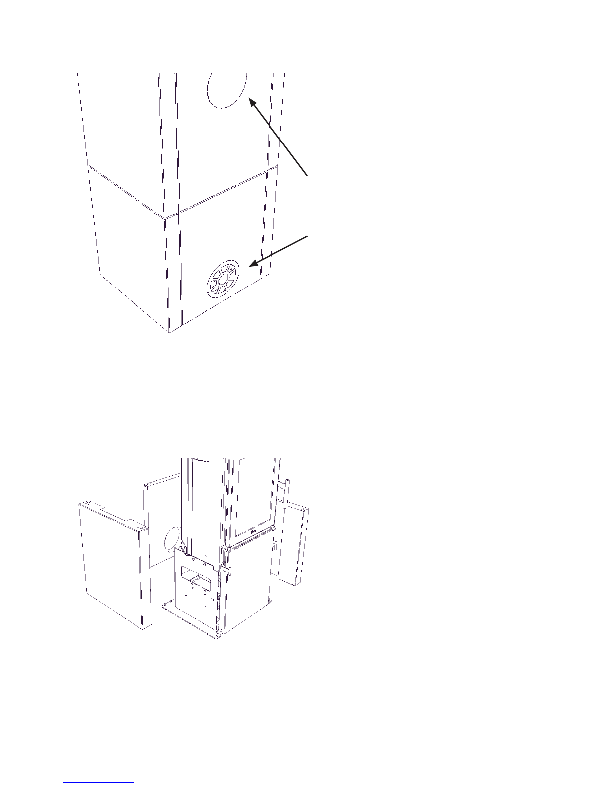
Fig. 3
Fig. 4
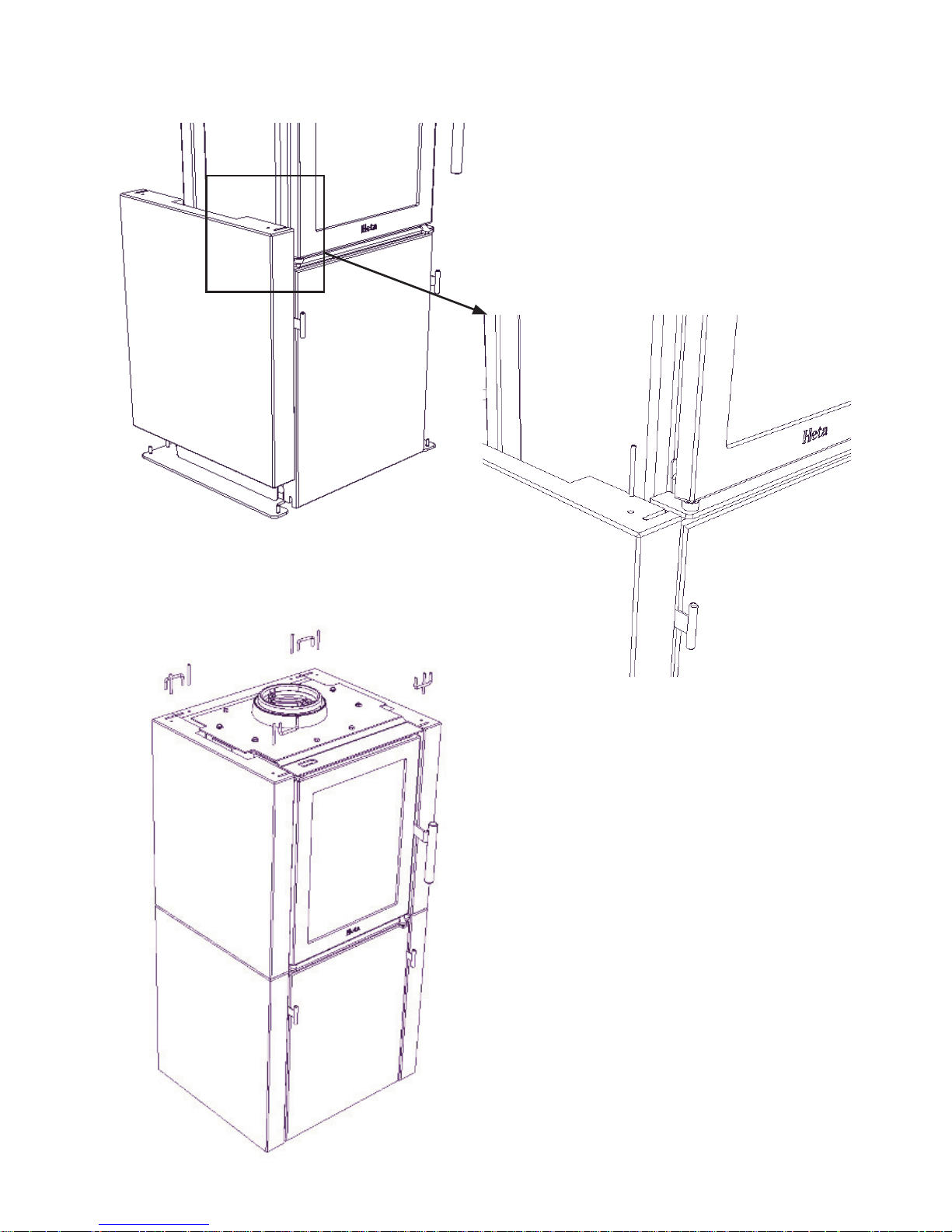
NB: Behind the stove, the stone with
hole for convection, must be placed at
the bottom. The next stone with hole
is put on top if there is smoke outlet
behind. Fig. 3
The closed cover should be placed
here unless the stove should be
mounted with back outlet
The open cover should be placed here.
Continue with sidestones as shown
i fig. 4. and place Brackets under.
Then place the backstone with
hole for convection and finish the
first round with af sidestone.
Page 23
23
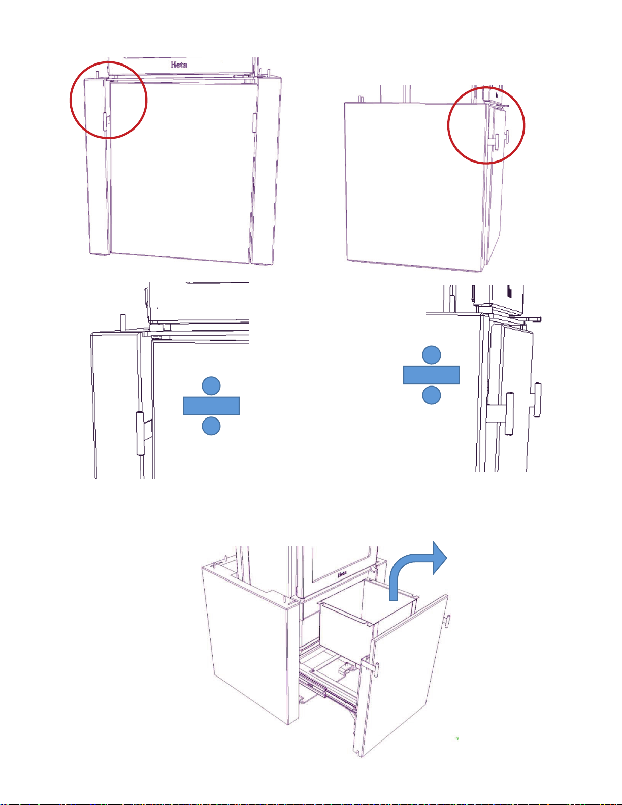
Scan-Line 50
Page 24
24
Scan-Line 50
Page 25
25
Scan-Line 50
Page 26
26
Scan-Line 50
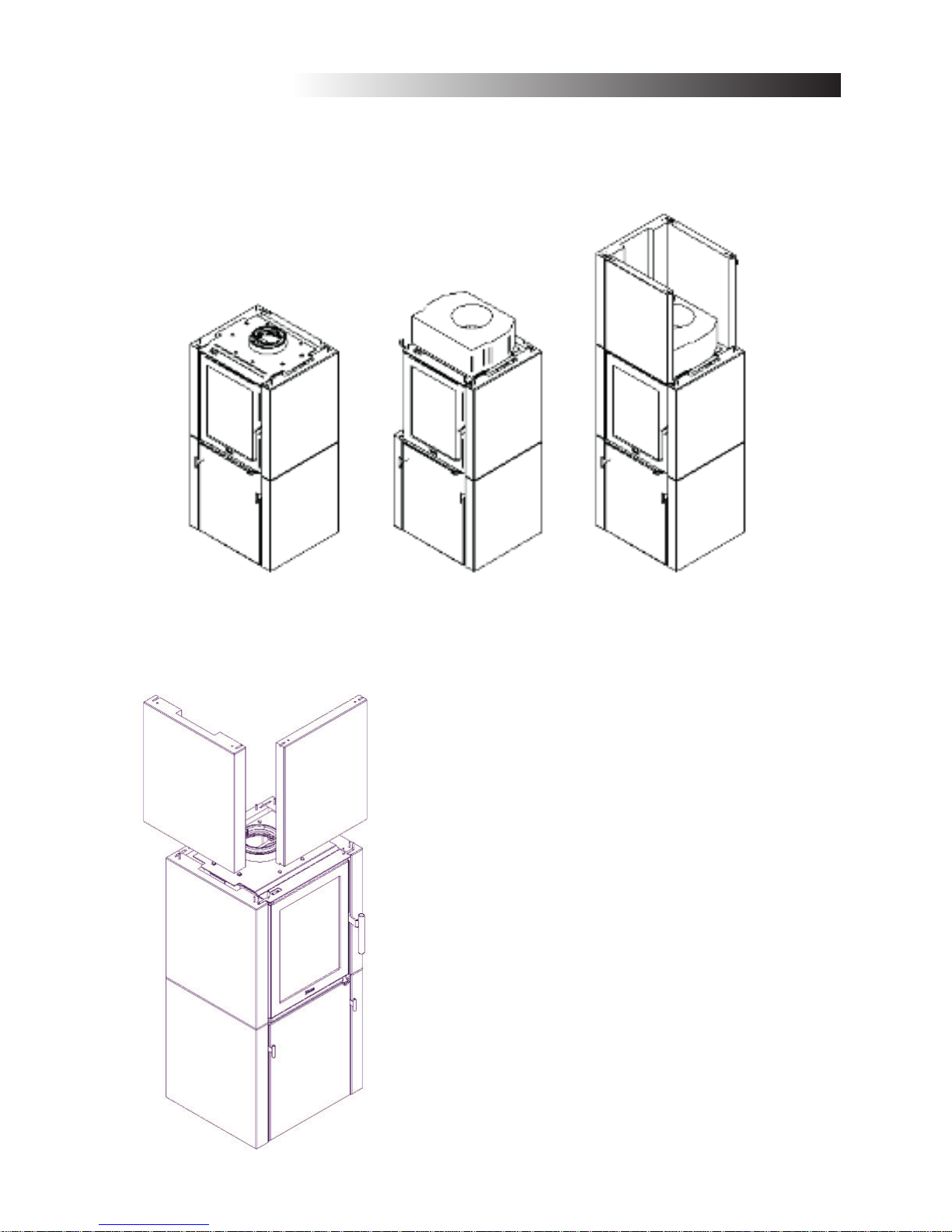
Fig. 5
Put brackets and pins in as shown. fig.
5.
Continuing with the next row. Start
with sidestone, backstone and then
sidestone again. Place brackets and
pins. fig. 6
Page 27
27
Scan-Line 50
THERMASTONES
Fig. 7
Step 1 Step 2 Step 3
Optional thermastones are also available. Six thermastones can be installed
in this stove.
The thermastones must be added after
the soapstones have been placed and
the stove/firebox has been adjusted.
Continue with the 3. row. Start with
the front stone with the two brackets
beneath (resting on the metal frame)
and then a side stone, which should be
placed on the pins/brackets. fig. 7
Page 28
28
Fig. 9
Fig. 8
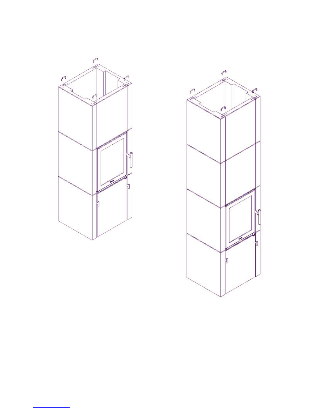
Continue with the back stone and
then another side stone. Place brackets and pins. See fig. 8
Place the last row of soapstone. Start
with the front stone, then side stone,
then back stone and side stone again.
Place brackes (no pins are required).
See fig. 9.
Scan-Line 50
Page 29
29
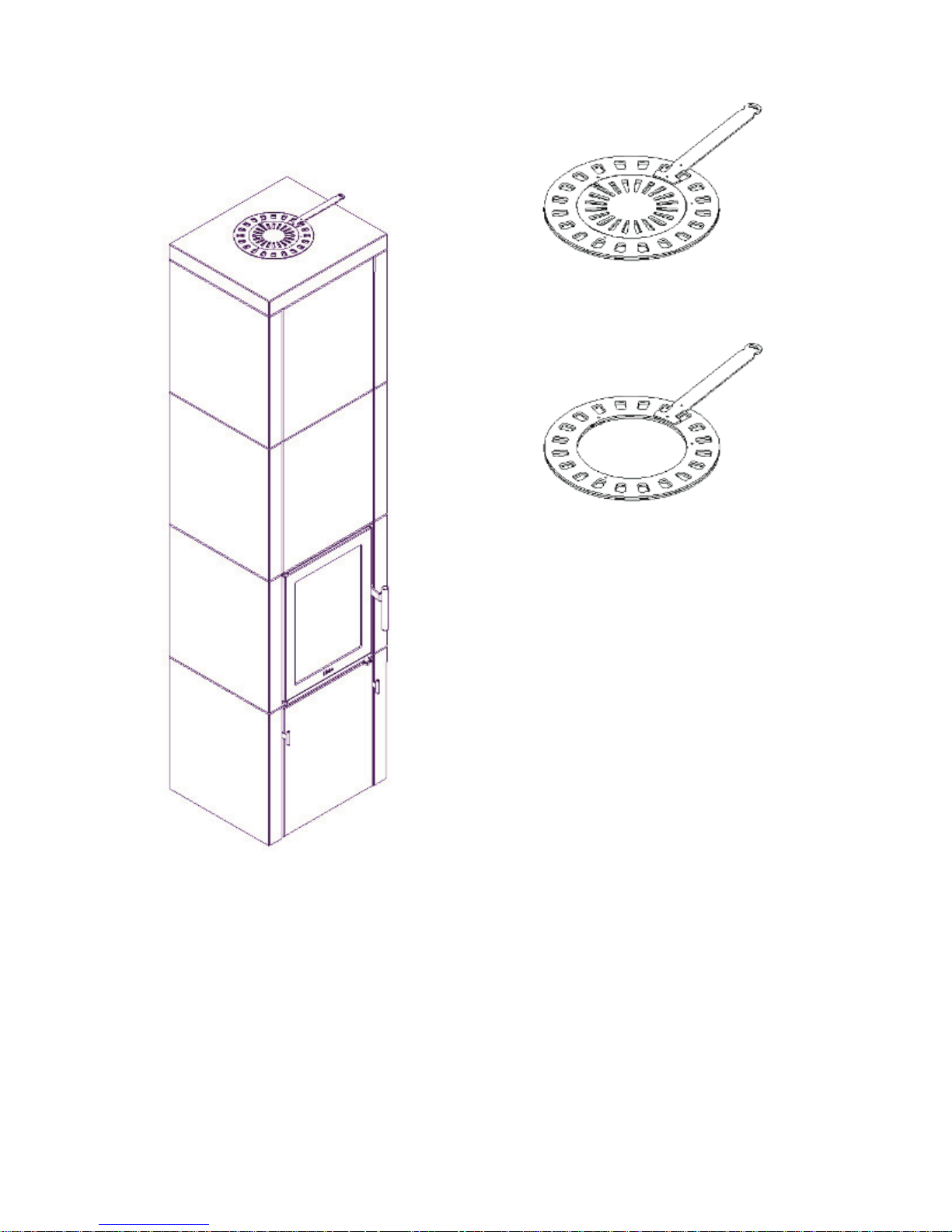
Fig. 10
Finish with the topstone - place it
loose on top. If the stove has a top
flue, break of the inner ring. Fig. 10
Top flue - break of the inner ring.
Scan-Line 50
Page 30
30
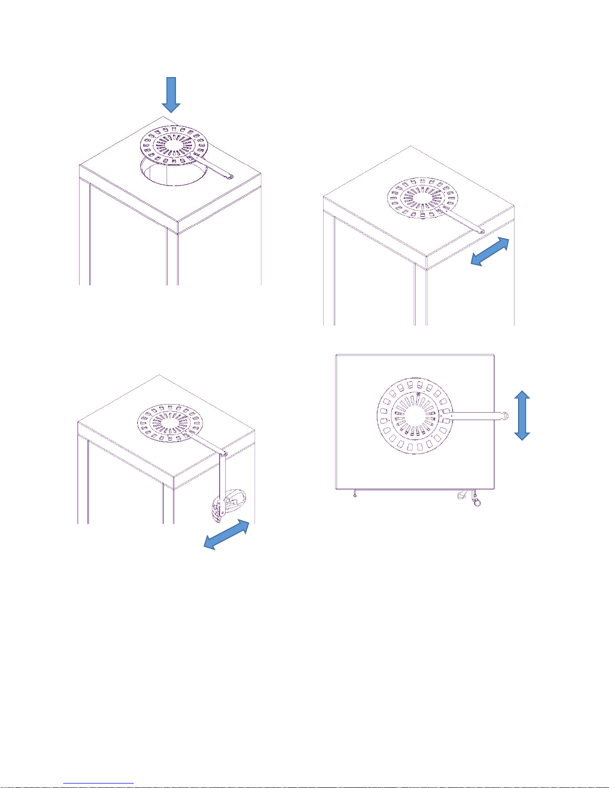
Regulate the convection air flow by turning the handle on the side of the stove.
Open
Closed
Scan-Line 50
Page 31

31
Page 32

32
17-11-2015 0037-1445
 Loading...