

Page 1
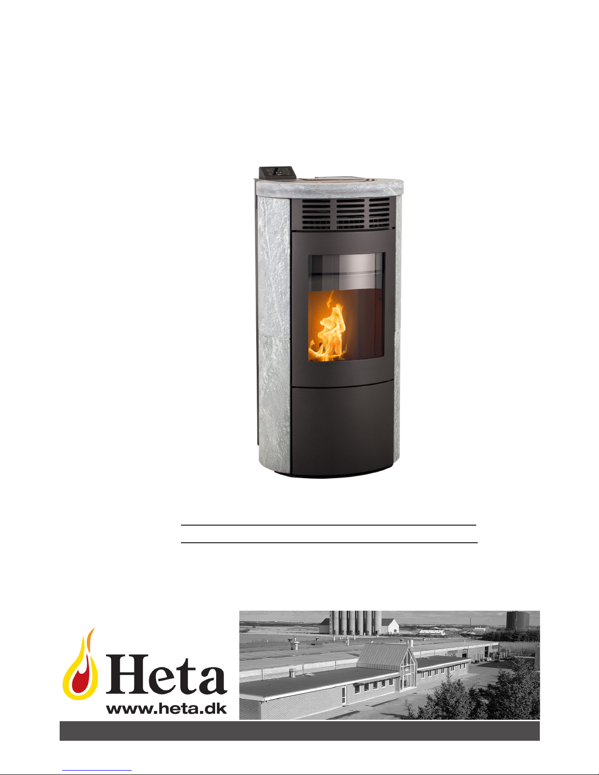
OPERATING GUIDE
GREEN200
UK
Danish Design • Danish Quality • Danish Produced
Page 2

Dear customer,
Congratulations on the purchase of your new pellet stove. We are confident that your investment
will provide you with excellent value and plenty of enjoyment, particularly if you follow the advice
and guidelines laid out in these instructions.
The Greenfire pellet stove is approved under EN 14785; NS 3058/3059; Austria’s 15a; DIN
plus
These approvals are your guarantee as a consumer that the pellet stove meets a number of specifications and requirements which confirm that the stove is made of high-quality materials, that it
is economical to use, and it is not harmful to the environment.
Please read these instructions for use carefully prior to installation and operation to avoid personal injury or damage to building parts or the product itself.
HETA A/S
Copyright © 2014. HETA
Jupitervej 22, 7620
Lemvig, Denmark
Tel. +45 96 63 06 00
E-mail: [email protected]
We accept no liability for printing errors and
reserve the right to change the contents without notice.
Heta and Greenfire are
registered trademarks
belonging to Heta A/S.
Printed in Denmark.
First edition, 2015.
Revision 1.01 UK
Page 3

3
CONTENTS:
1. Introduction ...................................................................................................................4
2. Safety information .........................................................................................................4
3. General information ......................................................................................................5
3.1. Liability .......................................................................................................................5
3.2. Spare parts .................................................................................................................5
3.3. Safety systems ...........................................................................................................5
3.4. Filling wood pellets .....................................................................................................6
4. Dimensions, installation and ignition .........................................................................7
4.1. Dimensions .................................................................................................................7
4.2. Placement ..................................................................................................................7
4.3. Temporary power failure ............................................................................................7
4.4. Minimum distance to combustible materials .............................................................8
4.5. Proximity to combustible materials ............................................................................8
4.6. The stove’s flue gas system .......................................................................................8
4.7. Chimney draught ........................................................................................................8
4.8. External air supply ......................................................................................................8
4.9. No ignition in the burn pot ..........................................................................................8
4.10. Before the first ignition .............................................................................................9
5. Menu structure, Operations and Timer .......................................................................9
5.1. Menu structure ...........................................................................................................9
5.2. Control Panel ............................................................................................................10
5.3. Remote control .........................................................................................................10
5.4. Menu navigation .......................................................................................................11
5.4.1. Active touch buttons ...........................................................................................11
5.4.2. Set the clock .......................................................................................................11
5.4.3. Manual pellet advancement ................................................................................11
5.4.4. Set the room temperature ...................................................................................11
5.4.5. Anti freeze ...........................................................................................................12
5.4.6. Select heat level ..................................................................................................12
5.4.7. Select convection level ........................................................................................12
5.4.8. Set pellet quality ..................................................................................................12
5.5. Sub menus ...............................................................................................................13
5.5.1. The settings menu ...............................................................................................13
5.5.2. Time menu ...........................................................................................................13
5.6. Timer settings ...........................................................................................................14
5.6.1. Setting programmes ............................................................................................14
5.6.2. Setting days ........................................................................................................15
6. Explanations ................................................................................................................16
6.1. Start up sequence ....................................................................................................16
6.2. Room temperature control .......................................................................................16
7. Troubleshooting ..........................................................................................................17
7.1. Alarm and error descriptions ....................................................................................17
7.2. Intro to troubleshooting ............................................................................................18
7.2.1. Troubleshooting the stove ...................................................................................18
7.2.2. Test run of stove ..................................................................................................19
7.2.3. Is the stove not burning cleanly ..........................................................................19
7.2.4. Before calling a service technician ......................................................................20
8. Warranty conditions ....................................................................................................21
9. EU declaration of conformity .....................................................................................22
10. Nameplate ..................................................................................................................23
11. Cleaning and service .................................................................................................24
Page 4

4
Accompanying your pellet stove you will find:
a. Operating Guide
b. Cleaning brush
c. Power cable
d. Heta glove
e. Remote control
f. Nameplate
1. Introduction
NB !!!
We advise you to read these instructions carefully, as they describe what you need to do to
ensure your Greenfire pellet stove functions to
its full potential.
Warning
The regulations relating to installation and function described in these instructions may differ
from the applicable regulations in the destination country. If this is the case, the regulations
applicable in the destination must be observed.
Drawings in these instructions are approximate
and not to scale.
Information
The packaging used provides good protection
against damage that might arise during transportation of the stove. Please check the stove
immediately upon delivery. If you notice any
visible signs of damage, contact your dealer
without delay.
Description of the stove
The aim of these instructions for use and servicing from Heta is to give the user all the necessary safety information, in order to prevent
any personal injury or damage to stove components or other items. Please read these instructions carefully before using or performing
maintenance on the appliance.
2. Safety information
Your Greenfire pellet stove must be installed
by a technician who has been trained by HETA
A/S. Please read these instructions regarding
use and maintenance carefully before installing
and lighting the stove! If you need further information, please contact the dealer from whom
you purchased the stove.
NOTE
The stove has extra protection in line with power regulations, and must have an earthed
electrical connection.
Only quality pellets with a diameter of 6-8 mm
should be used as fuel.
Before connecting power to the stove, make
sure that the connection between the stove
pipe and chimney is in place.
Never remove the protective grate above the
pellet tank.
The stove must be installed in a room with adequate air replacement.
Never open the stove door while the stove is
operating. When the stove is lit, the surfaces,
glass, handle and stove pipe will be very hot.
While the stove is operating, these components
may only be touched if wearing appropriate
protection.
3. General information
The Greenfire pellet stove must only be installed in residential environments. The stove has
fully automatic control, ensuring controlled
combustion. The control system manages the
ignition process, five heat levels and shutdown,
ensuring that the stove functions correctly.
The design of the bowl used for combustion
ensures that most of the ash from the pellets
falls into an ash drawer. However, you should
check the burn pot each day, as not all pellets
are of equal quality.
Air flow is used to help keep the glass clean,
however it is impossible to avoid the glass becoming sullied after some usage (see the cleaning manual for cleaning instructions).
Only pellets 6-8 mm in diameter should be
used as fuel in the Greenfire pellet stove.
Page 5
5
3.1. Liability
By providing these instructions, Heta A/S disclaims all liability, both personal and statutory,
for any accidents that may arise due to failure
– either fully or in part – to observe the instructions enclosed herein.
Heta A/S disclaims all liability in relation to incorrect use of the stove, abnormal usage by
the customer, unauthorised replacement and/
or repair, or the use of non-original spare parts
for this model
The manufacturer disclaims all liability, both
personal and statutory, direct and indirect, attributable to:
• Inadequate maintenance
• Failure to observe the instructions in this
manual
• Failure to observe safety directions
• Irregular installation with failure to ob
serve applicable standards in the
destination country
• Installation carried out by unqualified or
untrained personnel
• Replacement or repair not authorised by
the manufacturer
• Use of non-original spare parts
• Extraordinary events
3.2. Spare parts
Use only original spare parts.
If you have any questions concerning your
pellet stove, Heta strongly recommends that
you contact your dealer immediately.
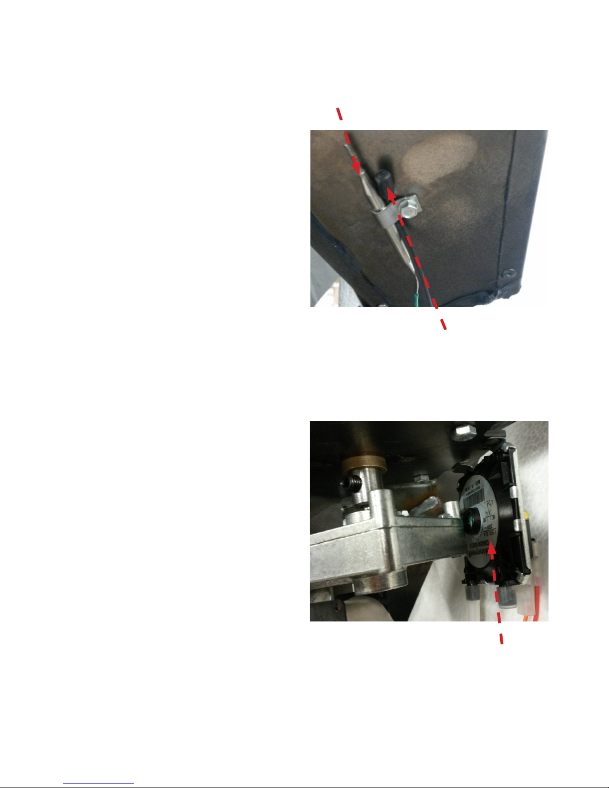
3.The pressure sensor measures whether there
is sufficient draught in the chimney. If problems
with inadequate draft or a blocked chimney
arise, the pressostat shuts down the stove.
(press the reset button to reactivate the stove)
1. Thermal protection shuts down the stove if
the temperature in the wood pellet tank becomes too high (85°C).
3.3 Safety systems
Greenfire pellet stoves are equipped with advanced safety systems to prevent damage
to the stove or residential environment which
could arise due to a fault in the appliance or
inadequate maintenance, chimney draught, etc.
If a fault occurs, pellet feeding ceases and
the stove shuts down automatically.
The stove has the following three safety systems:
2. The thermal sensor in the pellet tank activa-
tes at 82°C and automatically reduces
the heat level. If this fails to achieve a drop in
temperature, the thermal protection (1) is activated
Page 6
6
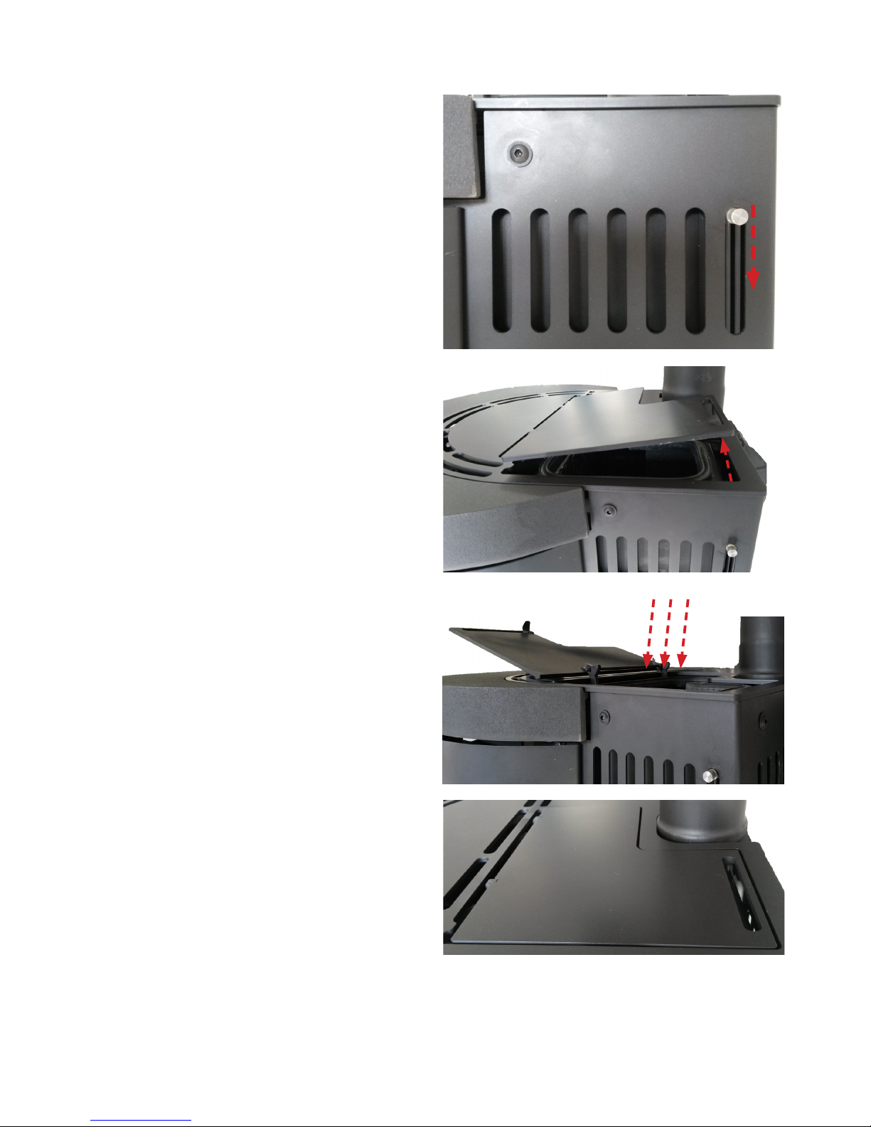
3.4. Filling wood pellets
Push the button downwards as shown.
The pellet lid now opens.
Open the lid full and fill in pellets.
Close the lid again.
Be sure to advance the pellets manually using the control panel (see section 5.4.3.) until pellets
appear in the burn pot. This ensures the correct start-up sequence.
Page 7
7
4. Dimensions, installation and ignition.
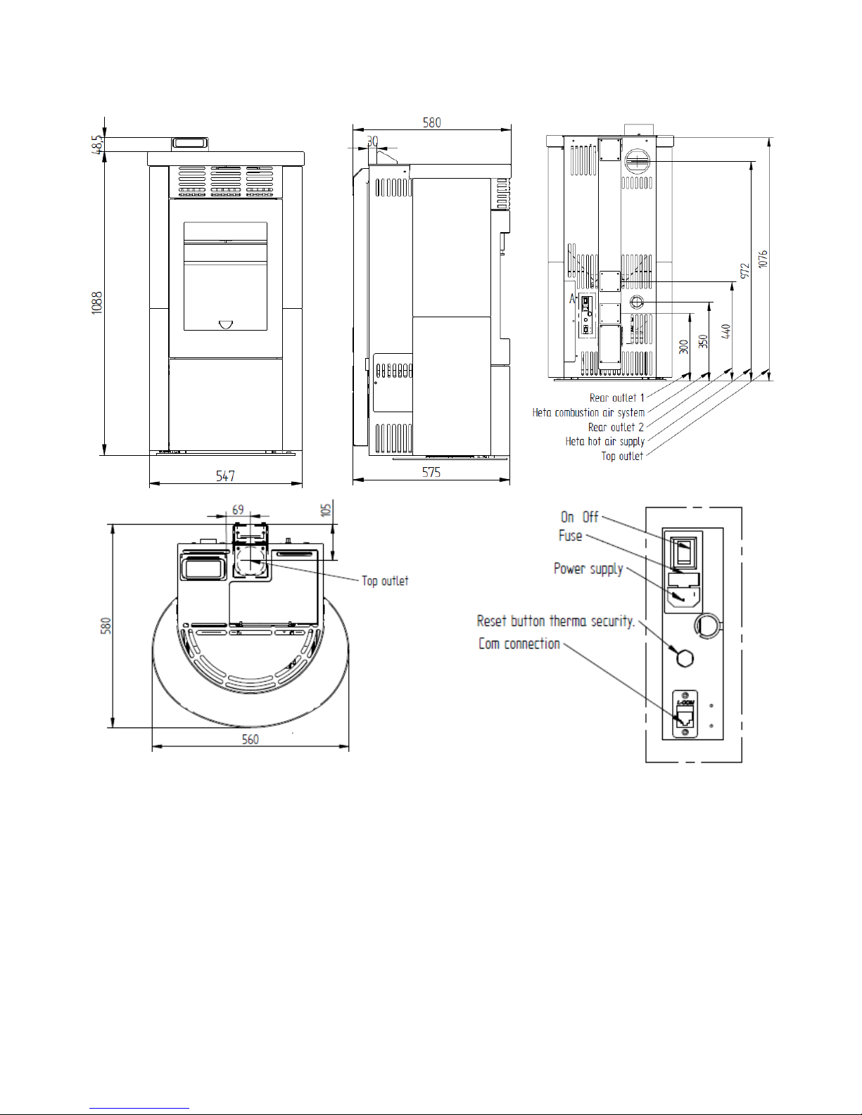
4.1 Dimensions
4.2 Placement.
The position of the stove within the home will
have a major impact on heat distribution.
Before deciding where to place the stove, it is
important to consider the following:
a) The air supply for combustion must
come from a ventilated room or an open
outdoor area.
b) Installation in a bedroom is not advised.
c) The stove must be installed in a spaci-
ous and central location in the house to
ensure the best heat distribution.
The electrical connection must be with Protective Earth (if the cable included is not long
enough to connect to the closest power outlet,
use an extension cord with a Protective Earth
connection)
4.3 Temporary power failure
If the power failure only lasts a few seconds,
the stove will restart and function normally. The
control system automatically shuts down the
stove in the event of protracted power failure.
The duration of the shutdown phase may vary
greatly, depending on the stove temperature.
Page 8
8
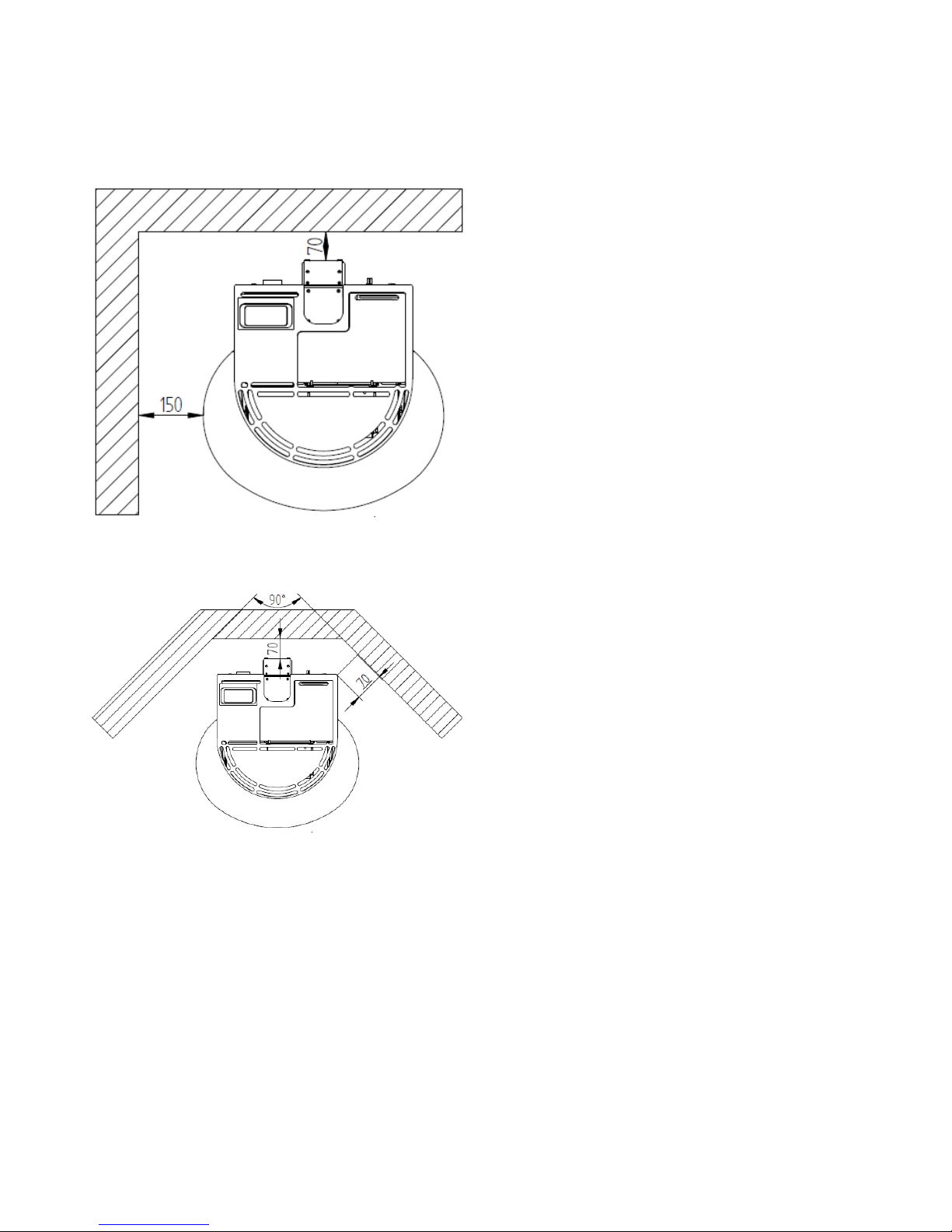
4.4. Minimum distance between the stove
and combustible materials
If positioned as shown, a minimum distance of
150 mm must be maintained from the wall, with
a gap of 70 mm behind the stove.
If positioned as shown, a minimum distance of
70 mm must be maintained from the walls.
4.6. The stove’s flue gas system
The flue gas system is dependent on a slight
underpressure in th e combustion chamber, and it is very important that the chimney
exhausts to outside air and not to an enclosed
or semi-enclosed room such as a garage, corridor, attic or anywhere else where the flue gases could become concentrated.
The chimney must always be installed in accordance with national and regional regulations
4.7. Chimney draught.
Operation of the Greenfire pellet stove is partly
independent of the chimney draught, as the
flue gas vacuum pump assists in removing
smoke from the combustion chamber. However, if there is a strong chimney draught, we
recommend a draught stabiliser be installed.
Otherwise the chimney will overrun the flue
vacuum pump, resulting in too much combustion. The stove operates best with a chimney
draught of 4 pascals (used for testing/approval)
in a chimney with a diameter of 80 mm
4.8. External air supply.
In hermetically closed environments with little
air replacement it can be difficult to supply
enough air for the combustion and it may be
necessary to supply extra air to the room.
4.9. No ignition in the burn pot.
During the ignition phase, it may be the case
that the stove fails to develop a flame. If the
stove fails to ignite, the control system will shut
down the stove and report an error ( no pellets )
4.5. Proximity to combustible materials.
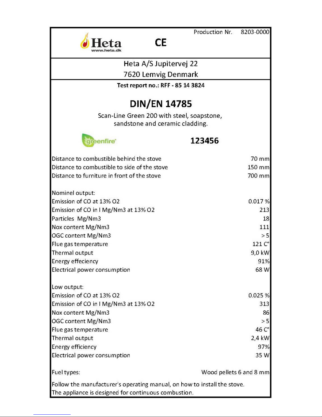
• Stove sides 150 mm
• Behind stove 70 mm
• Furniture in front of stove 700 mm
The following directions may vary, depending
on regional or national directives.
Applicable legislation in the country in which
the stove is being installed must always be respected.
If in doubt, contact your authorised Heta dealer.
Page 9
9
4.10. Before the first ignition.
1) Read these instructions carefully before lighting the stove.
2) Install the control panel and cable supplied. (See section 4.2.)
3) Correctly connect the pellet stove to the chimney
4) Fill the pellet tank (diameter 6–8 mm)
5) Open the door and check that the burn pot is in place in the frame and that the baffle
plate is at the top of the combustion chamber
6) Close the stove door. Never open the stove door while the stove is operating.
7) Roll out the room temperature sensor placed at the rear of the stove and ensure it is
not in contact with hot surfaces.
8) Connect the stove to a power outlet using the cable supplied.
9) Use the control panel to configure all personal settings and then start the stove.
(See the section on operating the stove)
NB:
The first time the stove is lit it is important to ventilate the environment very well, as an unpleasant odour may arise during the first few hours of operation as the paint hardens.
Allow the stove to operate at the highest level for a few hours to ensure the paint is hardened the first time the stove is used, so the unpleasant odour does not occur again.
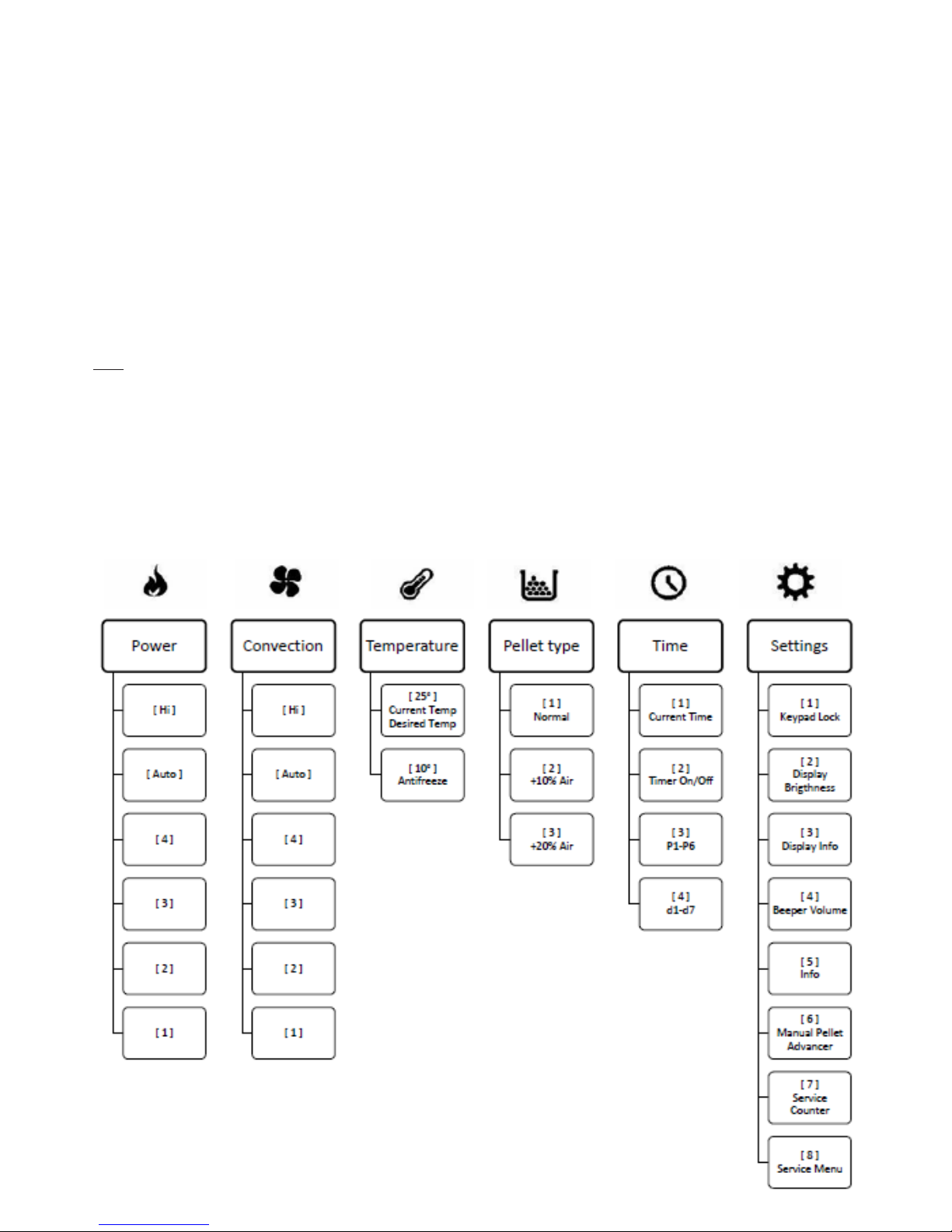
5.0. Menu structure, Operations and Timer
5.1. Menustructure
Page 10
10
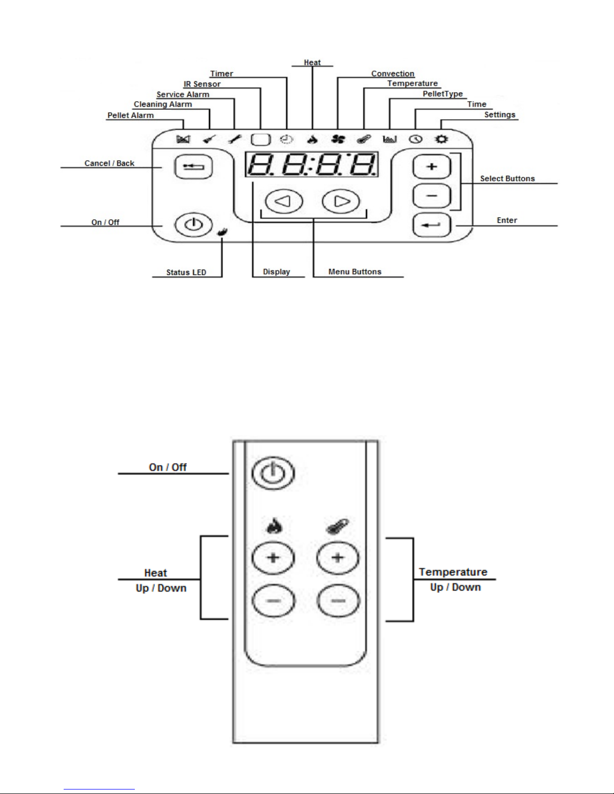
5.2. Control panel
The control panel has an audio tone for alarms, etc.
• Short tone: When buttons are pressed on the control panel.
• Long deep tone: If something is entered incorrectly on the control panel.
• Long high tone: Stove alarm, accompanied by an error code on the display.
5.3. Remote control
Page 11
11
5.4. Menu navigation
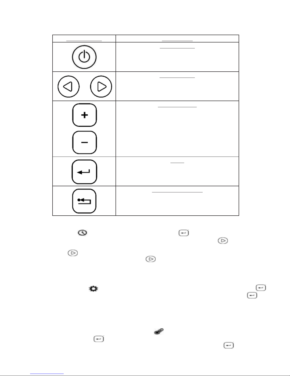
5.4.1. Active touch buttons
5.4.2. Set the clock
Use the Time menu to set the time and date. Press Enter and the hour setting starts to
flash. Use the + / – buttons to set the correct hour. Then press the Arrow Right menu button.
The minutes setting will then start to flash. Use the + / – buttons to set the correct minutes. Press
the Arrow Right menu button and the date will be displayed. Set this in the same way as you
set the time (above). Then press the Arrow Right button and select the appropriate day of
the week. (1 = Monday, 2 = Tuesday, and so on).
5.4.3. Manual pellet advancement
Go to the Settings menu . Press + until point ( 6 ) is shown in the display. Then press Enter
and the display will ‘roll’, which indicates manual pellet advancement. Press and hold Enter .
This sequence lasts approx. 30 seconds. Repeat the sequence until pellets appear in the burn
pot. Then empty the burn pot to ensure the correct start-up sequence.
5.4.4. Set the room temperature
Set the room temperature in the Temperature Menu . The current room temperature setting
will be shown. Press Enter to set the desired room temperature. The display will flash and
you can select the desired room temperature using the + / – buttons. Press Enter to confirm.
(The room temperature can also be set using the remote control. See section 5.3. )
Touch button: Description:
On/Off button
Switches the stove On or Off if pressed and
held for more than three seconds
Menu buttons
Used to navigate within the menus
Editing buttons
Used to navigate and edit within the menus
Enter
Used to confirm entries and select sub menus
Cancel/Back button
Cancels entries/returns to the previous menu
item
Page 12

12
5.4.5. Antifreeze temperature (Frost protection).
Antifreeze is a setting to prevent the room temperature falling too low – frost protection, in other
words. If the current room temperature falls below the Antifreeze temperature entered, the stove
will start automatically. The Timer must be ON for the Antifreeze system to activate.
Use the Temperature menu to set the Antifreeze temperature. Press + and [2] will be displayed. Press Enter
Adjust the Antifreeze temperature to the appropriate setting and press Enter to confirm.
(the default setting is 10°C )
5.4.6. Select heat level
Use the Heat menu to set the stove’s heat level. Press Enter and select the desired maximum heat level for your stove. 1…4, Auto, Hi. Press Enter to confirm.
(You can also use the remote control to set the desired heat level. See section 5.3. )
5.4.7. Select convection level
The convection fan is set to Auto by default and follows the Heat level automatically in this setting. We recommend that you always set the convection fan to Auto, as there is a risk of a combustion fault if the convection fan is set incorrectly.
5.4.8. Set pellet quality
Use the Pellet Type menu to set the pellet quality. Press Enter to select one of the following three options:
1 = Standard setting. ( ENplus A1 )
2 = Standard + 10% extra air for combustion.
3 = Standard + 20% extra air for combustion.
Press Enter to confirm pellet type.
Page 13

13
5.5. Sub menus
5.5.1. The Settings menu
1: Keypad lock: Off, Lo, Hi (This sub-menu is used to select one of the following options)
Off = Unlocked, (You can always choose Keypad Off under this item)
Lo = Enter button locked,
Hi = Enter button and On/Off button locked
2: Display Lighting: 1, 2, 3, 4, 5 (This sub-menu is used to select one of the following options)
1 = Low 5 = High
3: Display Info: Off, 1, 2, 3 (This sub-menu is used to select one of the following options)
Off = Display continues to show the menu selected.
1 = Display alternates between room temperature and time.
2 = Display alternates between the menu selected and room temperature.
3 = Display alternates between the menu selected and time.
4: Beep Volume: 1, 2, 3, 4, 5 (This sub-menu is used to select one of the following options)
1 = Low 5 = High
5: Technical Info
6: Manual Pellet Advancement (See section 5.4.3. )
7: Service Counter (Number of hours ON until service, 0–999 hours, 999+ hours = Hi )
8: Service Menu
5.5.2. Time menu
[ 1 ] = Current time
Used to select the time, date, year and day of the week.
[ 2 ] = Timer On/Off
Used to switch the Timer function On or Off.
[ 3 ] = Programme 1 to 6 ( P1, P2, P3, P4, P5, P6 )
Used to set programme 1 to 6 with On/Off, time and temperature.
(See Section XXX )
[ 4 ] = Day 1 to 7 ( d1, d2, d3, d4, d5, d6, d7 )
(d1 = Monday, d2 = Tuesday … d7 = Sunday)
Used to set the days with associated programmes.
( See Section XXX )
Page 14
14
5.6. Timer settings
5.6.1. Setting programmes
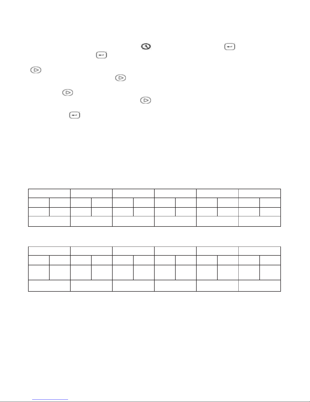
To set a Programme, go to the Time menu , Sub-menu [3]. Press Enter and the display
shows [ P1 ]. Press Enter and the display shows Start time (On, see below), with the hours
setting flashing. Press + or - until the hour figure you require is flashing. Then press Arrow Right
and the minute number will start to flash. Press + or - until the minute figure you require is
flashing. Then press Arrow Right and the display will show Stop time (Off, see below), with
the hours setting flashing. Press + or - until the hour figure you require is flashing. Then press
Arrow Right and the minute number will start to flash. Press + or - until the minute figure you
require is flashing. Then press Arrow Right and the temperature reading will start to flash.
Press + or - until the maximum temperature you require is flashing. Confirm the temperature by
pressing Enter and the entire programme 1 [ P1 ] will be saved in Timer.
Repeat this process for the other programmes if you wish to use them as well.
Example 1:
Program 1 Program 2 Program 3 Program 4 Program 5 Program 6
ON OFF ON OFF ON OFF ON OFF ON OFF ON OFF
5:30 7:30 8:00 11:30 12:00 23:00 17:00 23:00 20:00 22:30 4:00 7:00
21° 21° 18° 24° 20° 22°
Chart for own use.
Program 1 Program 2 Program 3 Program 4 Program 5 Program 6
ON OFF ON OFF ON OFF ON OFF ON OFF ON OFF
Temp: Temp: Temp: Temp: Temp: Temp:
Page 15
15
5.6.2. Setting days
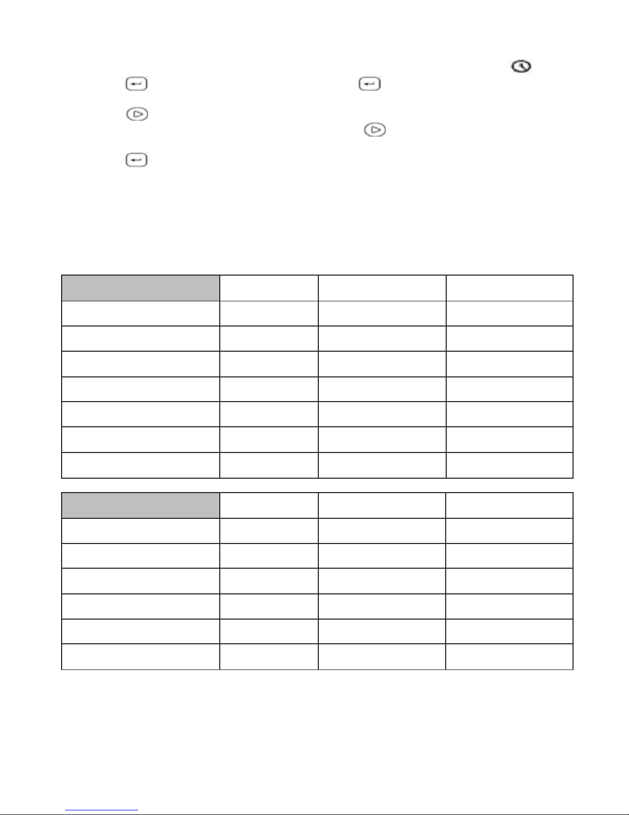
To set up a day with one or more programmes, go to sub-menu [ 4 ] in the Time Menu .
Press Enter and [ d1 ] will be displayed. Press Enter and the display will show Off
(block A, see below). Press + until the programme you require (Off, P1 to P6) is displayed. Press
Arrow Right and the display will show Off (block B, see below). Press + until the programme
you require (Off, P1 to P6) is displayed. Press Arrow Right and the display will show Off
(block C, see below). Press + until the programme you require (Off, P1 to P6) is displayed.
Press Enter to confirm.
Day 1 (d1 Monday) has now been set. Repeat this process for the other days if you wish to use
them as well.
Example 2:
A B C
d1 - Monday
p1 p4 off
d2 - Tuesday
p1 p4 off
d3 - Wednesday
p6 off off
d4 - Thursday
p6 p4 off
d5 - Friday
p6 p5 off
d6 - Saturday
p2 p3 off
d7 - Sunday
p1 p3 off
Chart for own use.
A B C
d1 - Monday
d2 - Tuesday
d3 - Wednesday
d4 - Thursday
d5 - Friday
d6 - Saturday
Page 16
16
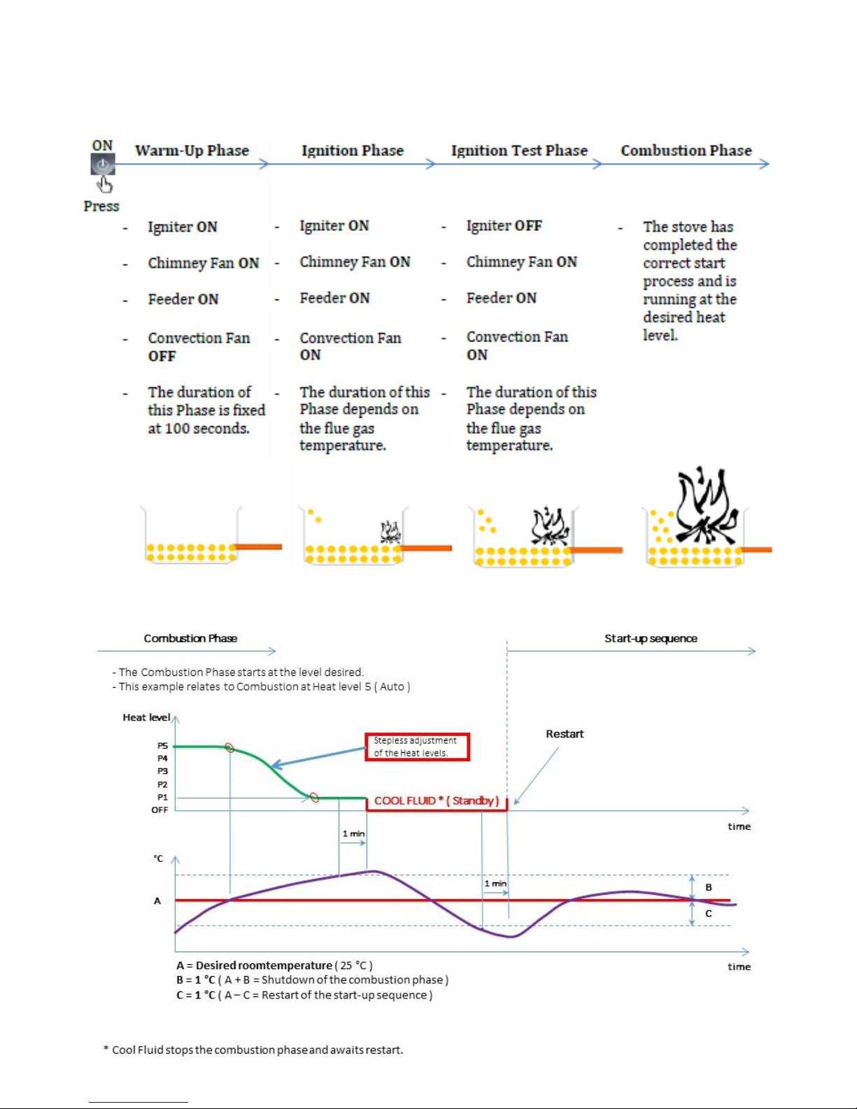
6. Explanations
6.1. Start up sequence
6.2. Room temperature control
Page 17
17
7. Troubleshooting
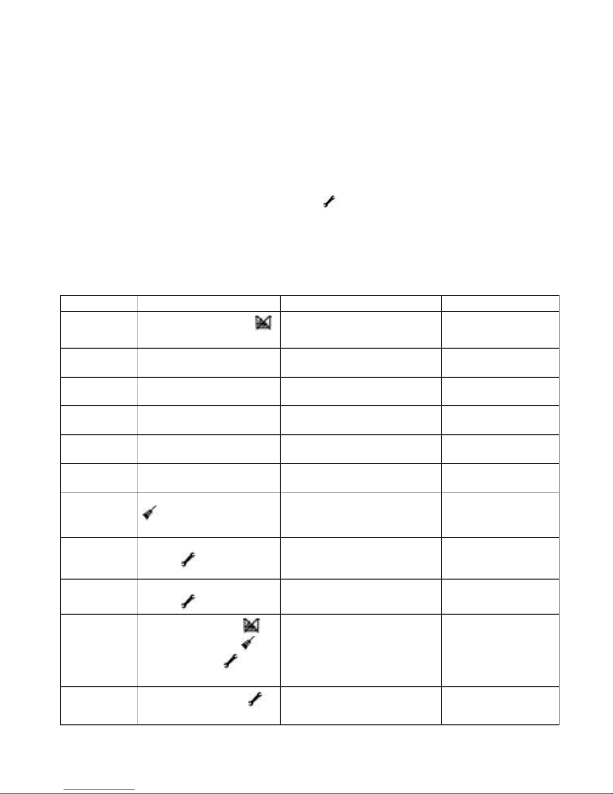
7.1. Alarms and errors
1. In the event of an alarm, one or more icons start to flash, and the problem ne
eds to be rectified without delay. In the event of an alarm, the stove may still
be partially usable. However, it will not be fully functional.
Contact a professional as soon as possible.
2. In the event of an error message, the icon will remain illuminated constantly,
and the problem must be rectified without delay. In the event of an error mes
sage, the stove will not function correctly. A professional MUST be contacted.
In that case, the Service Alarm icon will be illuminated constantly and the
code will start with an E.
3. Most alarms and errors have a code that helps to localise the problem. To view
this code, press the Back button on the control panel and keep it depressed
until the code appears in the display panel. If the display shows ‘- - - -’ there is
no code associated with the problem in question.
Errorcode: Description: Possible Error: Possible solution:
----
The Pellet Alarm icon
is illuminated constantly
The Pellet tank is empty Add pellets to the pel-
let tank
E004 Error in communication
with the control system
Com cable defective Contact your dealer
to arrange a solution
E106 Pellet Tank Temperature
sensor fault
Sensor defective Contact your dealer
to arrange a solution
E108 Pressostat / STB Pellet
Tank Safety sensor fault
Sensor defective Contact your dealer
to arrange a solution
E110 Room temperature sensor
fault
Sensor defective Contact your dealer
to arrange a solution
E111 Flue gas sensor fault Sensor defective Contact your dealer
to arrange a solution
A003 The Cleaning Alarm icon
ashes or is illuminated
constantly
Stove and/or chimney need
cleaning.
Check the cleaning
manual
A004 The Service Alarm icon
ashes.
The backup battery for the
control system is running low.
Contact your dealer
to arrange replace-
ment
A005 The Service Alarm icon
ashes.
Hall Speed Sensor on the
chimney fan is not working.
Contact your dealer
to arrange a solution
A006
The Pellet Alarm
Cleaning Alarm
Service Alarm icons
ashes.
Door switch not activated or
defective.
Contact your dealer
to arrange a solution
A007
The Service Alarm
icon ashes.
Pressostat activated / defec-
tive
Contact your dealer
to arrange a solution
If you have any questions, Heta strongly recommends that you immediately contact your
dealer.
Page 18

18
7.2. Intro to Troubleshooting
Compared to a conventional wood-burning stove, a pellet stove features a lot more mechanical
and electronic systems. As a result, a number of problems may arise that can have a negative
influence on both ignition and combustion.
It is a good idea to check through these troubleshooting guidelines before calling a service technician and/or submitting a complaint.
7.2.1. Troubleshooting
Before ignition, check that:
a) The iron lid in the top to the pellet tank seal tightly.
b) The burn pot is sitting tightly against the lower section, and that there is no ash or pellet
residue between the burn pot and the pipe in which it is fitted.
c) The seal on the ash pan is intact, and that the pan closes tightly against the stove.
d) The seal on the door to the combustion chamber is intact, and all edges of the door sit
tightly against the chamber.
e) The stove has been thoroughly cleaned as described in the cleaning section of this guide.
If there are faults in one or more of the areas mentioned above, rectify the fault and then test run
the stove.
Detailed explanations of sections a through e
Section a: If the seal between these parts is not tight, unwanted air will be drawn through the
pellet tank and into the stove. This air will not contribute to the combustion process – rather it will
reduce the volume of air used for combustion. The effect on/diminishing of the combustion process will be greater the fewer pellets are left in the tank, because the air resistance through the
tank falls in step with the quantity of pellets in it.
Section b: It is important that the burn pot is correctly positioned and forms a tight seal with the
stove, because the combustion air will otherwise flow around the pot. This will result in poorer
combustion and diminish the effect of the cleaning function. The diminishing effect on the combustion will increase proportionately to the soiling of the burn pot.
Sections c and d: It is essential to keep the ash pan and the seal on the door tight because even
a small leak will have serious consequences on the combustion. If the ash pan is even slightly
open, the stove will hardly be able to burn any fuel at all, and will quickly become dirty.
Section e: If this section is not cleaned regularly as described in this guide, it will also result in
faster soiling of the interior ducts in the stove and require more regular service visits involving
dismantling the stove and cleaning the insides of the pipes, ducts and chambers.
Page 19
19
7.2.2. Test run of stove
Start the stove and test all combustion levels (Auto, 4, 3, 2, and 1). During this process, it is
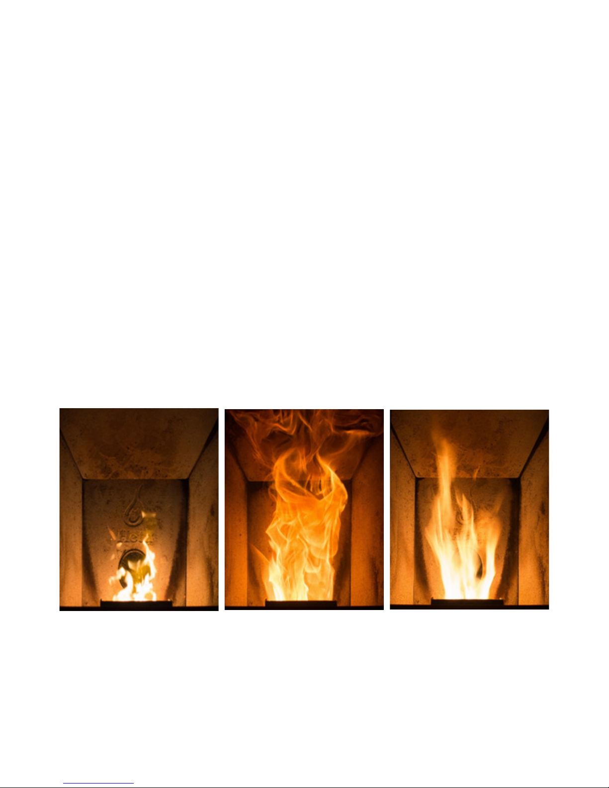
important to check that there is sufficient combustion airflow to the stove. The sign of a successful ignition process is that the flames are pale yellow after 15 minutes of operation – the flames
should also remain pale yellow if you turn the heat down. However, when adjusting to a lower
level, there will be a ‘conversion period’ given that the airflow is reduced and fewer pellets are delivered to the stove. This process will normally last for a few minutes, when the flames may burn
dark yellow or orange until optimal combustion is re-established (pale yellow flames).
7.2.3. Is the stove not burning cleanly?
If the stove settings are correct but the combustion produces dark flames, several factors may
be having an influence. Fuel, pellet type and chimney will be the most significant factors, and the
following section describes the relevant solutions.
The stove’s basic settings are based on a pure, pale pellet and a chimney with a draught of 12
pascals (like a standard wood-burning stove). If a different type of pellet is used (e.g. a dark, heavier pellet) or if there is insufficient draught in the chimney, it may be necessary to increase the
combustion airflow. You can make the relevant adjustments via the control panel. Go to the menu
for ‘Pellet type’ (see section 8.2.7 in the instructions for use). Level 1 is the standard setting, level
2 provides 10% extra air, and level 3 provides 20% extra air.
If this is not sufficient to achieve the combustion desired, and approved service technician/dealer can increase the airflow even more using the hidden parameters in the control programme.
However, this should only be necessary in exceptional cases – 10% or 20% extra air should be
sufficient. If the stove receives too much air – possibly as a result of a chimney with excessive
draught – it is likewise possible to reduce the airflow in the combustion process.
Too much air Right amount of airToo little air
Page 20

20
7.2.4. Before calling a service technician
If the stove burns only poorly – dark flames and black smoke – or does not burn at all, contact
your dealer to arrange a visit from a service technician.
When calling a service technician, it will really help the technician if you can answer the following
four questions.
Description of problem:
a) Does the problem arise during ignition, after a long period of operation or when the stove
is approaching the desired temperature?
b) Does it arise when you are using the Timer function and/or during ordinary operation?
c) Does it arise more/less often during specific weather conditions? Cold (great need for
heat) or hot weather (little need for heat)? Does it make any difference whether or not the
wind is blowing?
d) How long has the stove been in operation? Is it a problem that has suddenly occurred, or
it is an issue that has become worse over a period of time? Was this a problem from the
time that the stove was first connected?
Any other comment(s):__________________________________________________________________
______________________________________________________________________________________
______________________________________________________________________________________
______________________________________________________________________________________
______________________________________________________________________________________
______________________________________________________________________________________
______________________________________________________________________________________
______________________________________________________________________________________
______________________________________________________________________________________
______________________________________________________________________________________
Page 21

21
8. Warranty conditions
We would like to thank you for purchasing your Heta Greenfire pellet stove. We recommend that
you read:
- The instructions for installation, use and maintenance
- The warranty conditions specified below:
Heta wood-burning stoves are subjected to thorough quality inspections throughout the manufacturing process and before they leave the factory and are delivered to the dealer. The combustion chamber is therefore guaranteed against manufacturing defects for a period of five years.
Other components are guaranteed under the terms of the Danish Sale of Goods Act and carry a
two-year warranty.
The warranty does not cover:
- Wearing parts such as:
- Fireproof stones in the combustion chamber
- Glass
- Sealant tape
- Glass rope
- Stainless steel burn pot
- Any damage arising from inappropriate installation and/or treatment of the stove and/or
customer errors.
- Damage caused by incorrect use.
- Freight costs in connection with repairs under the guarantee.
- Assembly / disassembly in connection with repairs under the guarantee.
Using pellets of poor quality or pellets made of materials other than pure wood can damage stove
components. As a result, the warranty is considered null and void and the manufacturer’s liability
is forfeited.
Transport damage is not covered by the warranty. We therefore advise you to check the stove
immediately on delivery and to inform the dealer immediately if damage is discovered. The manufacturer’s warranty obligations are limited to those described above, and no claims can be made
on the basis of a verbal request.
When making a claim, please state the invoice no.
Warning
If unauthorised changes are made to your pellet stove and parts other than original spare
parts are used, the guarantee will be considered null and void.
Page 22
22
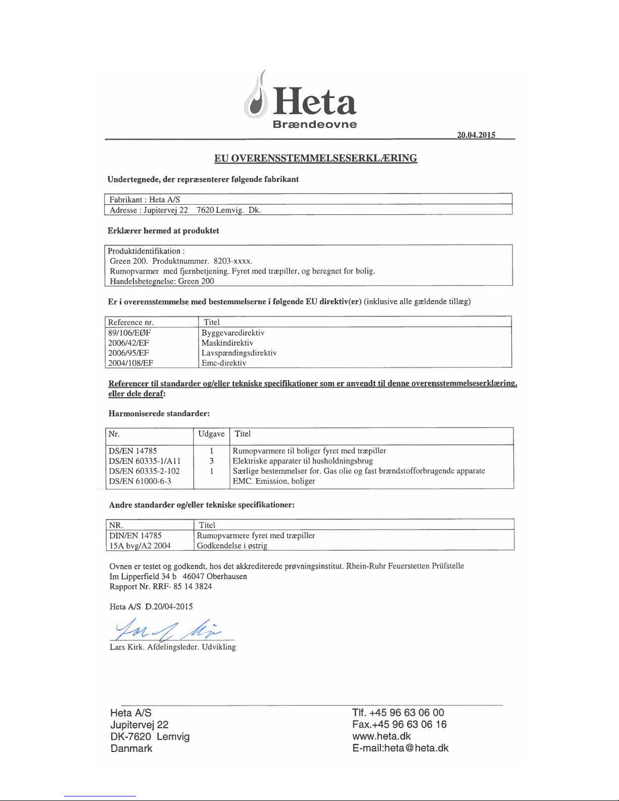
9. EU declaration of conformity
Page 23
23
10. Nameplate
Page 24
24
11. Cleaning, Maintenance and Service
11.1. Daily Cleaning
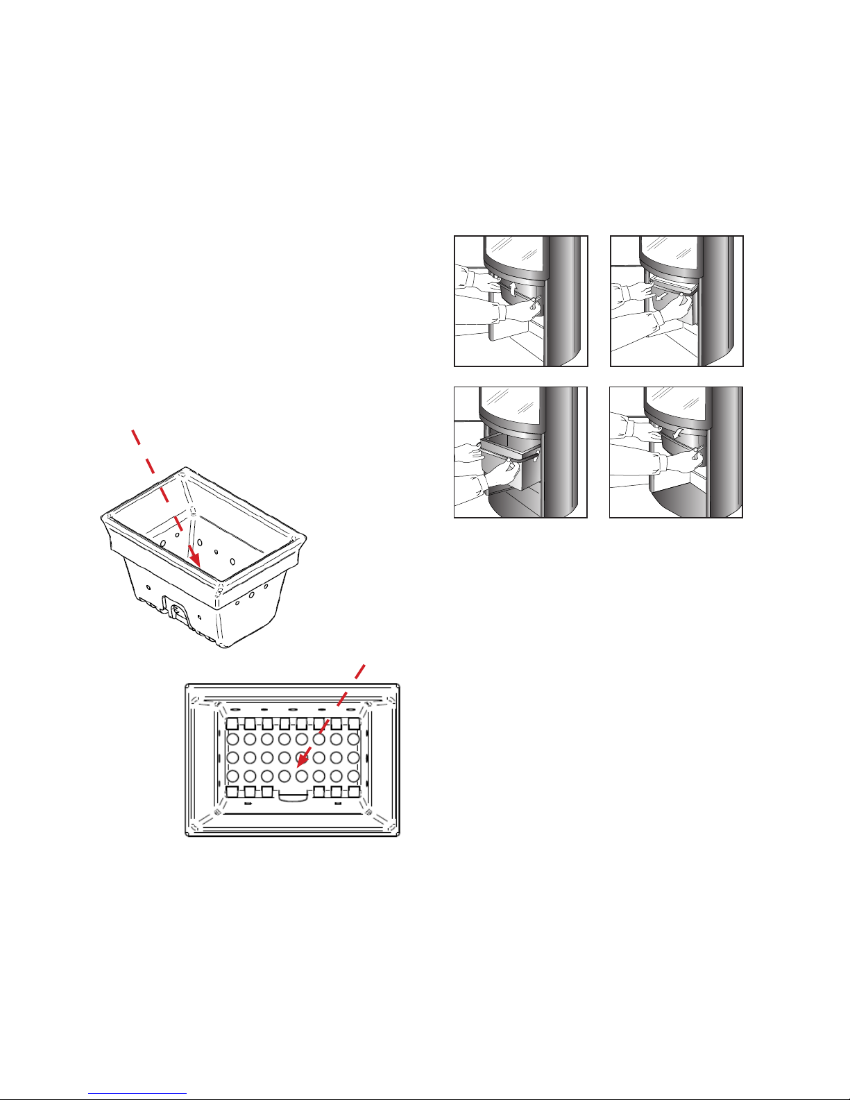
11.1.1. Cleaning the burn pot
A clean burn pot is essential to ensure the
pellet stove operates correctly and without
problems. During operation, baked on ash
deposits will develop and must be regularly
removed (as required), as these impede correct
combustion. Correct daily cleaning will ensure
the stove has optimal combustion and good
performance, and avoid operational failures
which may ultimately require assistance from a
technician to return the stove to working order.
Clean also the hole in which the burn pot sits,
as ash which falls through the burn pot will
impede airflow.
11.2.2. Cleaning the combustion chamber
The stove requires light but regular cleaning to
ensure stable operation. Clean the combustion
chamber every 2-3 days, for example using a
vacuum cleaner. Ensure that the ash is completely cool and all embers are extinguished.
NB: The combustion chamber stone are a
porous material and should be treated accordingly.
11.2.3. Cleaning the glass
Clean the glass whenever necessary. Depending on the pellet quality and heat level used
(a low heat level leads to more dirt/deposits),
deposits will eventually form on the glass. These can be removed using paper or a cloth and
glass cleaning agent. If the deposits are hard/
baked on, you can use a plastic pot scourer
and glass cleaning agent.
11.2. Weekly Cleaning
11.2.1. Cleaning the ash pan
The ash pan must be emptied about once a
week, depending on how often the stove is in
operation and the quality of the pellets.
Open the lower stove door to access the ash
pan.
Page 25

25
11.3. Monthly
11.3.1. Glass door seal and gaskets
It is important that the glass door seal, the ash pan gasket and pellet tank cover seals tightly, as
the stove requires underpressure in the combustion chamber for correct operation.
The glass seals must be replaced if worn, or glued in place using ceramic glue if loose.
Ask your dealer if you need assistance.
11.4. Semi annually / Annually
11.4.1. Emptying / Cleaning of the pellet tank.
Pellettank should be emptied and vacuumed for dust and pellet remains at least semiannually
11.4.2. Cleaning the flue gas channel
Clean the flue gas channel using the round steel brush supplied with the stove. Vacuum any ash
remainings inside the inspection hole at the front bottom of the stove.
11.4.3. Cleaning the Pressostat: (*)
The pressostat is connected to the chimney fan by a silicone hose. Clean the silicone hose if dirty
using water and soap (ensure it is completely dry before reinstalling). Apply suction to the pressostat inlet and listen to hear if it clicks.
11.4.4. Cleaning the convection fan (*)
Check that the convection fan turns easily by turning it with your fingers. Clean off dust and any
other dirt, for example using a soft brush.
11.4.5. Internal flue pipe and chimney fan (*)
The stove’s horizontal flue pipe must be kept free from ash and soot. Remove the chimney fan
and clean any ash or soot off the housing and blades.
Points marked with an asterisk (*) should only be carried out by an authorised dealer
Page 26
26
11.5. Service Interval
There is a built-in service counter set to 2.400 ON hours. To view the status of this service
counter, see the Settings Menu, Menu Item 7. This SERVICE COUNTER counts down from the
2,400 ON hours. If the amount of hours is more than 999 the display will show Hi. Once they
have expired, an alarm will be triggered in the form of a noise and two flashing icons. These icons
will continue to flash until an authorised service technician has completed a service procedure on the stove and reset the service counter.
(The stove can still be used in this period)
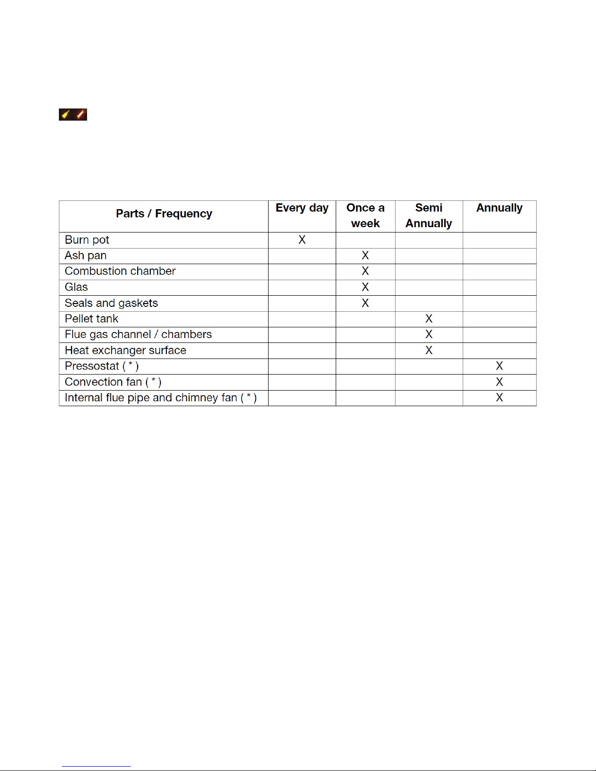
11.5.1. Cleaning Interval
Points marked with an asterisk (*) should only be carried out by an authorised dealer.
Tools suitable for cleaning can be purchased from your authorised HETA dealer.
If the directions and cleaning schedule in this cleaning manual are not observed the warranty will
become void.
 Loading...