

Heston Blumenthal HBG2S, HBG3M, HBG3O, HBG3G, HBG2R Assembly, Operating, And Maintenance Instructions
...Page 1

Assembly, Operation & Maintenance Instructions
1
FORCE
FURNACE
Assembly, operation &
maintenance instructions
for Everdure by Heston
Blumenthal FORCE™ &
FURNACE™ gas barbeques
and stands
TM
TM
everdurebyheston.com
0845-16
Page 2
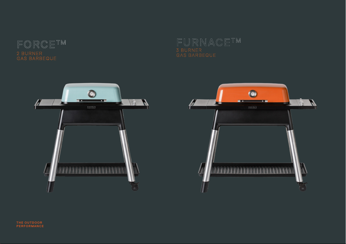
THE OUTDOOR
PERFORMANCE
FORCE
2 BURNER
GAS BARBEQUE
TM
FUR NACE
3 BURNER
GAS BARBEQUE
TM
Power by design.
Page 3

CONTENTS
Important Safety Instructions .........................................................................4-5
Appliance Details .................................................................................................. 6
Outdoor Installation Guide .................................................................................. 7
Operating Instructions ..................................................................................... 8-9
Ignition Procedure ...............................................................................................10
Cleaning & Storage ............................................................................................. 11
Troubleshooting ...................................................................................................12
Barbeque Assembly ....................................................................................... 13-17
Maintenance ........................................................................................................17
Parts List: Barbeque Assembly .....................................................................18-21
Assembly, Operation & Maintenance Instructions
3
OPERATION AND MAINTENANCE INSTRUCTIONS FOR HBG2G, HBG2M, HBG2S, HBG2R, HBG3G, HBG3M, HBG3S and HBG3O GAS BARBEQUE RANGE Everdure by Heston
Blumenthal outdoor gas barbeques. It is important that you retain these instructions, proof of purchase as well as other important documents about this product for future reference. Due to
continual product development, Everdure by Heston Blumenthal reserves the right to alter specications or appearances without notice. Dispose of packaging responsibly – recycle where
facilities are available.
Page 4

4
Assembly, Operation & Maintenance Instructions
IMPORTANT SAFETY INSTRUCTIONS
IMPORTANT: Read the safety precautions of this booklet carefully before removing
the barbeque from its carton or connecting the barbeque to its gas supply.
WARNING: Accessible parts may be very hot. Keep young children away.
1. This gas barbeque and stand set are intended for OUTDOOR USE ONLY. This
appliance must NOT be used indoors.
2. For your safety and enjoyment, read the instructions before using the appliance.
3. Ensure that all gas connections are tight before operating this appliance (refer to
leak testing procedure in this manual). Always check for leaks when a gas cylinder is
replaced or reconnected.
4. If not mounted on the cylinder hook, always place gas cylinder on a at level surface.
5. Unsupervised children or pets should not be near a barbeque whilst cooking or during
warm up or cool down. Ensure children or pets are kept a distance well away from the
barbeque whilst it is in use. Ensure that young children do not play with the appliance.
This appliance is not intended for use by young children or inrm persons.
6. Particular care must be taken when removing the fat tray and the disposable foil trays.
Mishandling of hot oil and fats can cause serious injury. Take care when changing plates
& grills that parts are not hot & oil or fat does not drop onto the burner. Take care that
the burner ports/venturi do not block up.
7. Turn gas valve/control knob and gas cylinder valve o after use. Do not allow build-up
of unburned gas.
8. Never leave the burners on high for more than 10 minutes unless actually cooking.
When cooking with the hood down, always follow the instructions in the Roasting
section of this manual.
9. Do not move the appliance during use. The barbeque should only be lifted by the
serveries at either side. Take care that undue pressure will not be placed on the gas
hose, or turn o the gas supply & remove the hose from the cylinder or gas source
(not at the barbeque). Take care that the fat tray & disposable aluminium foil tray are
removed to minimise fat/oil spillage. It is recommended that protective gloves be worn
when handling any hot components. Parts that are sealed by the manufacturer or agent
must not be altered.
10. This barbeque has been designed to be used either on the supplied trolley or on a
raised bench. When using a raised surface (table etc.), ensure the surface is level, large
enough and strong enough to support the barbeque and will withstand temperatures of
60°C above ambient temperature. When using the stand, ensure that your barbeque is
in a level position and the barbeque is secured onto the stand correctly (four screws at
the barbeque base).
11. People with ammable clothing such as nylon etc. should keep well away from the
barbeque when it is operating. This appliance must be kept away from ammable
materials during use.
12. Do not use this appliance for any purpose other than what it is intended for. Any
modication of the appliance may be dangerous. Do not modify the appliance.
13. In case of fat re turn cylinder o. The fat tray should be cleaned and checked before
using the barbeque. Disposable aluminium foil trays should be replaced before using the
barbeque. Regular cleaning should reduce the build-up of fat and food residues which is
combustible and can result in a fat re. Fat res can be prevented with diligence in
cleaning your fat tray and regular replacement of aluminium foil trays. Do not
allow the aluminium foil tray to overow. Damage as a result of fat re is not covered by
your warranty and voids it. Do not use sand, kitty litter or fat absorbents in the fat tray
or disposable aluminium foil tray.
14. Ensure that the product has adequate clearance from combustible materials. The
appliance is designed so that heat will not aect the stand. All combustible materials
must be kept more than 250 mm from the sides and rear of the barbeque and more
than 1500 mm above the cooking surface of the barbeque.
15. If a burner makes a hissing sound when lit, it may be burning inside. Turn the burner o,
allow to cool, and try ignition again. Keep your barbeque protected against strong wind
– if this cannot be avoided, always check that the burners remain alight if operating the
barbeque in windy conditions.
16. Do not carry out any servicing on the gas manifold of the barbeque yourself – this must
only be done by authorised technicians.
17. We recommend that you regularly maintain your barbeque and keep it in good condition.
This can be achieved by following the cleaning and maintenance suggestions in this
booklet.
18. When not using the stand, the cylinder should be placed at a lower level to the
barbeque, as far away as the hose will allow without undue tension on the hose, in a
Page 5

protected spot (so it does not receive any fat splatter from cooking or can be accidently
knocked over). When using the stand, hang the gas cylinder from the cylinder hook. If
this cannot be done (due to the design or size of the cylinder), the gas cylinder should
be placed beside or behind the appliance, in a safe position protected from any fat
splatter.
19. This appliance is not suitable for mounting in a movable vehicle (boat, trailer etc).
20. Do not use or store this appliance in areas of high salt content (a marine environment)
or an area with caustic fumes or liquids (such as a domestic pool), as these
chemicals can cause the appliance materials to deteriorate (and void the warranty).
Regular cleaning and covering with an Everdure by Heston Blumenthal barbeque
cover can help to reduce this.
21. The appliance shall be supplied with an approved hose which is certied to
applicable EN Standards that is not exceeding 1.5 m. For Finland, the hose length
shall not exceed 1.2 m. The gas regulator should be certied according to EN16129
(ow rate max. 1.5 kg/hr). These should be connected as per local regulations.
Position hose clamps and tighten. Do not allow the hose to kink or twist during installation and use. Change a new hose if leakage/blockage is sighted. It is suggested
that the hose is changed every 3 years.
DO NOT OPERATE THIS APPLIANCE BEFORE READING THE INSTRUCTION BOOKLET
DO NOT PLACE ARTICLES ON OR AGAINST THIS APPLIANCE
DO NOT STORE CHEMICALS OR FLAMMABLE MATERIALS OR SPRAY AEROSOLS NEAR THIS APPLIANCE
DO NOT OPERATE THIS APPLIANCE INDOORS
DO NOT ENCLOSE THIS APPLIANCE. THE MINIMUM CLEARANCE FOR THIS UNIT IS 1500 mm ABOVE THE COOKING
SURFACE AND 250 mm FROM ANY SIDE
DO NOT LIGHT WITH HOOD DOWN
Assembly, Operation & Maintenance Instructions
5
Page 6

6
Assembly, Operation & Maintenance Instructions
APPLIANCE DETAILS
Note: The size of the injector diameter is stamped on one of the hexagon faces (e.g. ‘165’ for Ø1.65 mm injector).
MODEL
DESIGNATION
TM
FORCE
FURNACE
PIN CODE: 0845CR0069
Barbeque
Barbeque only LENGTH
Barbeque and
stand
BE, FR, IT, LU, IE, GB, GR, PT, ES , CY, CZ,
LT, SK, CH, SI ,LV
LU, NL, DK, FI, SE, CY.CZ, EE, LT, MT, SK,
SI, BG, IS, NO, TR, HR, RO, IT, HU, LV
AT, DE, CH, LU, SK 2x3.9kW 2 φ0.83mm I 3B/P(50) Butane, Propane and their mixtures at 50mbar
TM
BE, FR, IT, LU, IE, GB, GR, PT, ES , CY, CZ,
LT, SK, CH, SI ,LV
LU, NL, DK, FI, SE, CY.CZ, EE, LT, MT, SK,
SI, BG, IS, NO, TR, HR, RO, IT, HU, LV
AT, DE, CH, LU, SK 3x3.2kW 3 φ0.74mm I 3B/P(50) Butane, Propane and their mixtures at 50mbar
(mm)
1170 515 410 1310 515 410
1170 750 1170 1310 750 1170
DESTINATION COUNTRIES HEAT INPUT BURNERS INJECTOR
2x3.9kW 2 φ0.95mm I 3+(28~30/37) Butane at (28~30) mbar/ Propane at 37 mbar
2x3.9kW 2 φ0.95mm I 3B/P(30) Butane, Propane and their mixtures at 30mbar
3x3.2kW 3 φ0.85mm I 3+(28~30/37) Butane at (28~30) mbar/ Propane at 37 mbar
3x3.2kW 3 φ0.85mm I 3B/P(30) Butane, Propane and their mixtures at 30mbar
FORCE
WIDTH
(mm)
TM
HEIGHT
(mm)
FURNACE
LENGTH
(mm)
WIDTH
(mm)
TM
HEIGHT
(mm)
Air is admitted at the underside of the combustion chamber (two 35 mm x 20 mm gaps
between the fat tray and the chamber through an oval hole 75 mm x 135 mm in size).
Exhaust gases are emitted around the edge of the plates (6 mm gap) and through a 275
mm x 40 mm slot in the rear of the hood. When using an open grill, aeration also takes
place through the slots of the grill. Burner aeration 17.8 mm x 5 mm both sides.
SIZE
GAS
CATEGORY
GAS TYPE
Page 7

Assembly, Operation & Maintenance Instructions
7
GAS CONNECTIONS
BUTANE & PROPANE GAS REQUIREMENTS
Check Gas Type and specications plate on the underside of the RHS servery.
FOR GAS CYLINDER CONNECTION
1. To achieve the optimum performance from your barbeque, an approved gas cylinder/
bottle must be used. The supplied hose and/or regulator must rst be connected to the
barbeque inlet.
2. Do not connect a gas cylinder/bottle to a barbeque that is not secured in the supplied
stand or on a stable raised surface. The cylinder should be lower than the barbeque, in a
protected place on a stable surface.
3. Before connecting gas supply, take care that all gas control knobs are in the O
position. Take the supplied Propane (37mbar) snap on regulator and adjust the regulator
handle to O. Press the regulator down onto the cylinder valve until a click is heard.
Once connected, turn the regulator handle to On to turn on the gas supply. Check all
joints are secure.
4. To remove the regulator from the cylinder, turn the regulator handle to O, press the
handle inwards and lift the regulator away from the cylinder valve.
NOTE: Only one gas cylinder should be stored on the stand at any one time.
LEAK TESTING
1. Make sure the gas control knob is O and turn the cylinder valve On.
2. Check for leaking joints by brushing with solution of half-liquid detergent and half water.
If a leak is present, bubbles will appear (or you may hear a hissing sound). Re-tightening
connections can generally repair a leaking joint. You must also check the gas hose and
connection at the gas cylinder. If a leak cannot be resolved, do not proceed and turn the
gas cylinder/bottle valve o.
DO NOT USE NAKED FLAME FOR LOCATING GAS LEAKS
IF A LEAK PERSISTS CALL AN AUTHORISED GAS FITTER
GAS CYLINDER
For mounting on the cylinder hook, the gas cylinder height cannot exceed 500 mm and
the diameter cannot exceed 320 mm. If larger, place the cylinder on a at level surface
where access to the cylinder valve is available, the hose does not come into contact with
sharp edges or hot surfaces, and where undue tension is not placed on the hose. Make
sure that the gas cylinder and the routing of the exible tube does not touch the trolley
of the appliance or any hot/sharp surface. Always change the gas cylinder away from any
source of ignition.
OUTDOOR INSTALLATION GUIDE
This appliance shall only be used in an above ground open-air situation with natural
ventilation, without stagnant areas, where gas leakage and products of combustion are
rapidly dispersed by wind and natural convection.
This appliance must not be used indoors. Do not use your barbeque in garages,
porches, sheds or other enclosed areas. The barbeque is not intended to be installed in
or used on recreational vehicles (e.g. boats, camping vans) and should not be placed
close to or under any surfaces that will burn or are sensitive to heat. Do not block/
obstruct the ow of air and combustion around the barbeque housing while in use.
Page 8

8
Assembly, Operation & Maintenance Instructions
OPERATING INSTRUCTIONS
GENERAL INSTRUCTIONS
A fairly protected location is desirable for pleasant and ecient cooking. Try to keep the
barbeque sheltered from strong winds as this will drastically reduce cooking eciency. If
this is unavoidable, position the length of the barbeque to be parallel in the direction of the
wind. Keep the barbeque level. Check frequently that the burner remains alight when used
in conditions of strong wind (through the viewing hole on the left hand side of the chassis
or through open grills). Make sure the minimum distances of the barbeque to any wall or
combustible surface are met, and that when not using the stand, the supporting surface
can withstand the heat. When using the stand, take care that the barbeque is locked in
position using the locks on the castors & the hose is not touching any hot surface.
GAS TYPE AND CONSUMPTION
The barbeques are designed to operate on Propane and/or Butane gas only. Gas
consumption, Pressure and Injector Orice sizes are shown on the Data Plate found under
the right hand servery.
GAS CONTROL KNOB
The gas control knob locks in both the O and High positions. By depressing the knob
and turning anti-clockwise, gas ow will gradually increase until the High position is
reached. Continue turning in this direction and gas ow will decrease until a simmer level is
reached at Low. To turn gas ow o, the gas control knob must be turned clockwise from
Low, depressed at High and turned until the O position is reached.
MATT VITREOUS CAST IRON OPEN GRILLS AND SOLID
PLATE
The FORCETM 2 burner and FURNACETM 3 burner barbeques are supplied with open grills.
A at, solid plate is available as an accessory for the FURNACETM for the right hand side
(this is the recommended general grill and plate conguration which will reduce the heat
owing over the control knobs). The FURNACETM 3 burner barbeque has the option of a
central teppanyaki plate or a at, solid plate for the right hand side. Note that the grills and
plates used on either barbeque cannot be used on the other model and a maximum of one
grill plate should be exchanged for a plate at any time (only one plate installed). The open
grills have a solid strip of cast iron built into the bottom of the grill used to protect the
burner from dropping oil or food. The grills are tted onto the supports built into the inside
of the chassis. When correctly allocated, there should be a 5-6 mm gap between the grills,
and the inner edge of the chassis. Any excess fat or liquid will ow into the chassis and
drip through the barbeque into the fat tray and foil tray below the chassis. If burner ports
become blocked, let the barbeque cool down & clean the burner with a wire brush. For a
list of accessories go to the Everdure by Heston Blumenthal website.
NOTE: The enamel coating can be damaged by steel utensils. Damage to plates and
grills due to the use of metallic or sharp objects will not be covered under warranty. It is
recommended to use silicone cooking utensils as these are both hygienic and withstand
high temperatures.
FAT TRAY
Prior to use, check that the fat tray is clean and lined with a disposable foil tray. Use only
foil trays supplied for the barbeque, as trays of an incorrect size or height could cause
problems with aeration to the barbeque or spilled fat and oils. Make sure the fat tray
assembly is fully installed under the barbeque before operating the appliance.
UNDER NO CIRCUMSTANCES MUST SAND, KITTY LITTER OR FAT
ABSORBENTS BE USED IN THE FAT TRAY OR FOIL TRAY.
Page 9

Assembly, Operation & Maintenance Instructions
9
ROASTING
Roasting (or running the barbeque with the hood down) should not be done with all
control knobs set to High. This is most important as severe overheating and spoilt food
can result if these instructions are not followed. Roasting is best done using a raised
roasting rack, such as the Everdure by Heston Blumenthal roasting rack HBROASTR,
which allows heated air to circulate around the meat, and fats to drip away from the meat.
Always set the barbeque up with the standard full grill combination as spelled out in the
assembly instructions. Cut a piece of foil slightly bigger than the roasting rack and place
it in the centre of the barbeque on top of the grills. Cut some slots through the foil so
that excess moisture and fats can ow through the grills. Place the roasting rack centrally
over the foil. Pre-heat the barbeque for 5 minutes with the hood down and the outer gas
controls on High (for FURNACE
Once the barbeque has reached ~180°C, open the hood, place the food on the roasting
rack, close the hood and turn the control knobs down to Low (these can be adjusted
during roasting to keep the internal temperature stable, as weather conditions such as
temperature and wind speed will aect the eciency of the barbeque). Monitor the food
cooking periodically until food is cooked.
TM
barbeques, leave the centre control knob o).
ADJUSTING THE SERVERY
The left hand servery can be folded down to allow for easier storage (the right hand
servery with the gas controls is xed and cannot be adjusted). With the barbeque o and
cool, place your left foot in front of the left rear leg to stabilise the barbeque and pull the
servery forward to unlock it from the barbeque. With the servery fully extended, rotate
it downward and release. See step 9 of the barbeque and stand assembly procedure for
diagrams.
AFTER COOKING
1. When nished, make sure burner control knobs are turned OFF.
2. TURN OFF THE GAS SUPPLY AT THE GAS CYLINDER AFTER USE.
3. After cooking and whilst the barbeque is still warm, remove scraps from the grill with a
non-metallic scraper.
4. Excess fat and meat scraps can be scraped o the inside of the chassis by removing
the grill/plate to gain access.
WARNING: Some surfaces may still be hot – please use protective gloves.
5. Clean the fat tray and replace the aluminium foil tray after or before each use of the
appliance.
6. Once the barbeque is cool close the hood and wipe o any fat splatter from the stand
with a clean rag.
Page 10

10
Assembly, Operation & Maintenance Instructions
LIGHTING PROCEDURE
READ ALL OPERATING INSTRUCTIONS BEFORE LIGHTING THE APPLIANCE
OPEN THE HOOD BEFORE LIGHTING
MAKE SURE THE GAS CONTROL KNOB IS IN THE ‘OFF’ POSITION AND OPEN CYLINDER/BOTTLE VALVE
MAKE SURE THE GRILL AND PLATE ARE IN THE CORRECT POSITIONS FOR COOKING
LIGHTING THE BARBEQUE USING THE BUILT IN
IGNITION ON THE CONTROL KNOBS
The FORCE
gas valves, accessed by using the control knobs built into the right hand servery. To ignite
a burner, push the appropriate control knob down and slowly rotate anti-clockwise. This
starts releasing the gas into the burner. As the knob reaches the ignition symbol on the
control panel, a spark will ignite the gas in the burner. The knob can then be rotated the
rest of the way to “High” and released, or adjusted to the appropriate temperature setting.
If the burner does not ignite, return the control knob to the “O” position and retry.
If there is still no ignition after 5 attempts, leave the barbeque o and retry again in 5
minutes time.
There are 2 control knobs on the FORCE
FURNACE
closest to the rear controls the burner to the right. The control knob closest to the front
controls the burner to the left. The central control knob (FURNACE
controls the centre burner.
TM
and FURNACE
TM
barbeques (one for each burner under a plate or grill). The control knob
TM
barbeques have a rotary ignition system built into the
TM
barbeques and 3 control knobs on the
TM
barbeque only)
CLEANING & STORAGE
EXTERNAL CLEANING
Before cleaning the barbeque exterior and stand, ensure the appliance has cooled and
is safe to touch. Painted and plastic surfaces can be cleaned using a mild household
detergent or cleaner and a clean cloth (do not use scourers or harsh detergents). It is
advisable to test cleaners on a small section of the appliance rst. NEVER use
paint thinners or similar solvents for cleaning and NEVER pour cold water over hot
surfaces. Dry the surface afterwards.
INTERNAL CLEANING
Before cleaning the internal parts of your barbeque, ensure the appliance has cooled and is
safe to touch. The inside of the hood can be cleaned by using some water, mild detergent
and a sponge or mild scouring pad. The non-stick coated surface of the hot plate should
be cleaned carefully so as not to scratch the surface as above, preferably when the
surface is still warm. For hard to clean areas, use a little baking soda on a wet sponge. Do
not use abrasive cleaners.
WARNING! The surfaces of the plates may be hot. Please ensure protective gloves are
worn.
Page 11

STORAGE
When the appliance is not in use, the cylinder valve must be turned O. The barbeque,
stand and the cylinder together must be stored outdoors in a well ventilated area.
However it is permissible to store the appliance (but not the cylinder) indoors. Ensure the
cooking surface is clean before storing away.
STORE CYLINDER IN A WELL VENTILATED AREA OUT OF
REACH OF CHILDREN
Assembly, Operation & Maintenance Instructions
11
When the gas cylinder is disconnected, replace the plug or cap on the valve outlet. For
extended storage it is suggested that the primary air-port of the burners be covered against
the penetration of insects or vermin. Spiders and small insects can spin webs or nest in the
burner rails/tubes, which could lead to obstruction in the gas and air ow, resulting in a re
in and around the burner rails/tubes. This type of re is called a ash-back and can cause
serious damage to your barbeque and create an unsafe operating condition. To prevent this,
regularly inspect and clean the burners. Use an Everdure by Heston Blumenthal FORCETM or
FURNACETM barbeque cover for extra protection and to reduce this.
Page 12

12
Assembly, Operation & Maintenance Instructions
TROUBLESHOOTING
Burner will not ignite when using the igniter:
Cylinder valve is not on Turn cylinder valve on.
Cylinder is empty Replace with a full cylinder/bottle.
Igniter is not sparking Remove grill/plate and visually check ignition box for a spark. Check that the cables to the ignition point, or from the valve to the chassis, have not
Injector is blocked Clean injector with a toothbrush. Do not drill out or use wire. Do not remove injector. Contact service provider.
Burner ame is erratic:
Burner is blocked Remove cooking surface and check burner for obstruction. Clean ports.
Flame is burning inside
burner (hissing sound)
Regulator is faulty Contact service provider.
Injector is partially blocked Clean injector with a toothbrush. Do not drill out or use wire. Do not remove injector. Contact service provider.
Gas is leaking from connections:
Connections are loose Tighten loose connections (do not over-tighten) and leak test under pressure with soapy water solution (page 7).
Hose has deteriorated Contact service provider - replace.
Gas valve is faulty Contact service provider.
Threads are damaged Contact service provider.
broken or disconnected. Also check the alignment of the sparker. If there is no spark, contact service provider.
Turn o burner, allow to cool and re-ignite as per instructions.
Page 13

Assembly, Operation & Maintenance Instructions
BARBEQUE AND STAND ASSEMBLY
The barbeque and hood come fully assembled. To assemble, the stand must rst be built (note: for transportation reasons, the barbeque is packaged bolted to the stand top, and
should be removed before attempting to assemble the stand). The barbeque is placed back inside the stand after it has been assembled and re-attached (it can be removed to
cook from a raised bench). Only a medium size Philips screwdriver is needed.
Open the carton from the top and remove the parts. Remove all packaging (especially check inside the barbeque chassis) and place parts on a clean surface. Check for any
damage or missing parts (if found, contact your service provider).
INCLUDED PARTS FORCE
TM
AND FURNACE
TM
13
01/ Hood, barbeque
chassis and 01B stand
top assembly x 1Pc
09 / Cast iron middle
grill x 1Pc
(FURNACE model only)
A / Bolt M6 x 12
x 11Pcs
02 / Left front leg
x 1Pc
10/ Cast iron grill x 2Pcs
(FURNACE model only)
B / Bolt M5 x 12
x 4Pcs
03 / Left back leg
x 1Pc
11 / Fat tray x 1Pc
C / Spring washer Ø5
x 6Pcs
04 / Right front leg
x 1Pc
12 / Cylinder hook
x 1Pc
D / Spring washer Ø6
x 5Pcs
05 / Right back leg
x 1Pc
13 / Gas cylinder support
chain x1Pc
E / Flat washer Ø6
x 4Pcs
06 / Bottom shelf
support x 2Pcs
14/ Hood Handle
x 1Pc
F / Bolt M5 x 15
x 2Pcs
07 / Bottom shelf
G / Flat washer Ø5
x 2Pcs
x 1Pc
08 / Cast iron grill x 2Pcs
(FORCE model only)
H / Nut M6
x 1Pc
PACKAGING
Remove all internal cartons and packaging from within the barbeque/hood assembly. Remove all external packaging and remove the appliance from the packaging base before
operation. Recycle as per your local government laws.
Page 14

14
Assembly, Operation & Maintenance Instructions
STEP 01
/ Open the hood and x the hood handle (14) using two M5x15mm screws (F), two
Ø5mm spring washers (C) and two Ø5mm at washers (G). Tighten in place.
STEP 02
/ The hood and barbeque chassis assembly is transported screwed to the stand top by
four M6x20mm screws and four Ø6mm spring washers (two at the front and two at the
rear). Before attempting to build the stand, the stand top should be removed.
1 4
Angle the assembly slightly to the back and remove both M6x20mm screws, then do the
same at the front, supporting the parts so they don’t drop. Keep all of the fasteners for
later use. Removable stickers at the front and rear will mark the positions of these screws.
Remove the hood and barbeque chassis assembly from the stand top and place on the
ground.
G
C
F
STEP 03
/ Take the stand top (01B) and place it upside down (leg stumps up) on a clean surface
(note: there is no front or rear to this part). Take the right front leg (04 with a screw
hole in the foot) and slot it over the rear right corner stump. Fix in place using a M6 x
12mm screw (A) and at washer (E), but do not tighten. Take the right rear leg (05 with
a screw hole in the foot) and slot it over the front right corner stump. Fix in place using a
M6 x 12mm screw (A) and at washer (E), but do not tighten.
Take the left front leg (02) and slot it over the rear left leg stump. Fix into place using a
M6x12mm screw (A) and at washer (E), but do not tighten. Take the left rear leg (03)
and slot it over the front right leg stump. Fix into place using a M6x12mm screw (A) and
at washer (E), but do not tighten.
Page 15

Assembly, Operation & Maintenance Instructions
15
STEP 04
/ Take the two bottom shelf supports (06) and t them onto the cylindrical tabs at the
inside of each foot. Rotate each one so that the outmost screw holes are facing inwards
and the inner screw holes are facing the stand top (if not, pull out and t in the opposite
way). Fix in place with four M6x12mm screws (A) and spring washers (D). When all are
assembled, tighten up all four screws and the screws from step 02.
STEP 05
/There are two threaded holes at the inside of the right hand legs. Take the support chain
(13) and x it to the two legs with two M6x12mm screws (A). Tighten fully.
STEP 06
/ Turn the stand onto its legs and check that all of the legs are stable. Take the plastic
bottom shelf (07) and place it on the two bottom shelf supports. Line the four holes in
the bottom shelf up with the threaded holes in the bottom tray supports and x into
position using four M5x12mm screws (B) and four spring washers (C). Tighten fully.
Page 16

16
Assembly, Operation & Maintenance Instructions
STEP 07
/ Push the at edge of the cylinder hook (12) into the slot of the stand top (above the
right hand side legs and castors) up until the dogleg, and then rotate down until the hook
is against the stand top side. Fix into place using a M6x12mm screw (A), M6 locking nut
(H) and spring washer (D). The stand is now complete.
STEP 08
/ Position the stand with the castor wheels to the right. Two people should lift the
barbeque and hood assembly (01A) by the serveries, and place it within the stand
(facing forwards, castors to the right). Fix the barbeque to the stand top with the four
M6x20mm screws and M6 spring washers removed at step 1 – two to the front and two
to the rear. Tighten fully.
STEP 09
/ To extend the left hand side servery, support the front of the barbeque and pull the left
hand servery forward (approximately 1cm) tensioning the spring. Rotate the left hand
servery to the vertical position and allow the tension in the spring to pull the servery into
place.
STEP 10
/ Fit the fat tray (11) and disposable foil tray into the brackets at the bottom of the
barbeque. Take care that the fat tray is allocated correctly.
STEP 11
/ Place the grills onto the barbeque as shown in the diagrams. Each grill should have a
5-6mm gap around each edge. Each grill will allocate in a groove on a plate support.
Page 17

Assembly, Operation & Maintenance Instructions
17
FORCE
FURNACE
STEP 12
/Connect an approved hose and/or regulator to the inlet manifold (if not already
connected). Hook the gas cylinder onto the support hook (12) and lean it against the
support chain. Connect regulator to the gas cylinder/bottle and leak test (as per the gas
connections instructions). Check all hose connections are tight, and that all control knobs
are o before turning on the gas supply and leak testing.
MAINTENANCE
It is recommended that at the commencement of each barbeque season the following
maintenance be conducted.
BURNER
1. Brush the outside of the burners with a sti brush to remove rust and dirt. Make sure
all ports are open.
GAS SUPPLY
1. Inspect the gas supply hose for any deterioration and replace it if necessary.
2. Test the gas circuit for leaks and remedy any found.
BARBEQUE AND HOOD
1. Wipe over the outer areas of the barbeque and hood with a clean cloth.
STAND
1. Check all fasteners for tightness and re-tighten where necessary to ensure rigidity of
the structure.
2. Wipe over barbeque stand with a clean cloth. Add a little oil or grease to all moving
parts.
If connected to the barbeque, check the screws holding the barbeque and stand
together are all tted and tight. Wear and tear to this barbeque can be reduced
by using a barbeque cover and storing out of the weather when not in use.
Page 18

18
Assembly, Operation & Maintenance Instructions
PARTS LIST: FORCETM BARBEQUES
PART NAME
1 Hood HBG2 (Mint) 1
Hood HBG2 (Stone) 1
Hood HBG2 (Graphite) 1
Hood HBG2 (Red) 1
2 Temperature Gauge Bezel 1
3 Temperature Gauge 1
4 Hood Handle Spacer 2
5 Hood Handle 1
6 Hinge 2
7 Right Hand Burner (HBG2) 1
8 Hardware Kit (not shown) 1
9 Barbeque Chassis (HBG2) 1
10 Control Knob 2
11 Control Knob Bezel 2
12 Right Hand Side Servery (HBG2) 1
13 Gas Ignition Crossover Box (HBG2) 1
14 Electrode (HBG2) 2
15 Left Hand Burner (HBG2) 1
16 Open Grill (HBG2) 2
17 Servery Spring 2
18 Left Hand Servery 1
QTY
19 Injector Bracket (HBG2) 1
20 Injector Housing 2
21 Injector (HBG2) 2
22 Injector Housing Nut 2
23 Fat Tray Bracket (HBG2) 2
24 Barbeque Chassis Feet 4
25 Fat Tray Handle Cover 1
26 Fat Tray 1
27 Gas Tube Support 2
28 Gas Tube (HBG2) 2
29 Valve Support 2
30 Hose/Regulator 1
31 Gas Valve & Manifold Assembly (HBG2) 1
32 Stand Top Front/Rear Panel (HBG2) 2
33 Stand Top Spacer Bracket 4
34 Stand Top Side Panel 2
35 Spacer Bracket 4
36 Stand Top RR/FL Cap 2
37 Stand Top RL/FR Cap 2
38 Leg FL 1
39 Leg RL 1
40 Disposable Foil Tray 1
41 Bottom Shelf (HBG2) 1
42 Leg Cap RR 1
Page 19

43 Leg Cap FR 1
44 Bottom Shelf Support 2
45 Castor 2
46 Foot FL 1
47 Foot RL 1
48 Leg FR 1
49 Leg RR 1
50 Gas Cylinder Support Chain 1
51 Cylinder Hook 1
Assembly, Operation & Maintenance Instructions
19
Page 20

20
Assembly, Operation & Maintenance Instructions
PARTS LIST: FURNACETM BARBEQUES
PART NAME
1 Hood HBG3 (Orange) 1
Hood HBG3 (Mint) 1
Hood HBG3 (Stone) 1
Hood HBG3 (Graphite) 1
2 Temperature Gauge Bezel 1
3 Temperature Gauge 1
4 Hood Handle Spacer 2
5 Hood Handle 1
6 Right Hand Burner (HBG3) 1
7 Hinge 2
8 Hardware Kit (not shown) 1
9 Barbeque Chassis (HBG3) 1
10 Control Knob 3
11 Control Knob Bezel 3
12 Right Hand Side Servery (HBG3) 1
13 Gas Ignition Crossover Box (HBG3) 2
14 Electrode (HBG3) 3
15 Left Hand Burner (HBG3) 1
16 Open Grill (HBG3) 2
17 Servery Spring 2
18 Left Hand Servery 1
QTY
19 Injector Bracket (HBG3) 1
20 Injector Housing 3
21 Injector (HBG3) 3
22 Injector Housing Nut 3
23 Fat Tray Bracket (HBG3) 2
24 Barbeque Chassis Feet 4
25 Fat Tray Handle Cover 1
26 Fat Tray 1
27 Gas Tube Support 2
28 Gas Tube (HBG3) 3
29 Valve Support 2
30 Hose/Regulator 1
31 Gas Valve & Manifold Assembly (HBG3) 1
32 Stand Top Front/Rear Panel (HBG3) 2
33 Stand Top Spacer Bracket 4
34 Stand Top Side Panel 2
35 Spacer Bracket 4
36 Stand Top RR/FL Cap 2
37 Stand Top RL/FR Cap 2
38 Leg FL 1
39 Leg RL 1
40 Disposable Foil Tray 1
41 Bottom Shelf (HBG3) 1
42 Leg Cap RR 1
Page 21

43 Leg Cap FR 1
44 Bottom Shelf Support 2
45 Castor 2
46 Foot FL 1
47 Foot RL 1
48 Central Burner (HBG3) 1
49 Central Open Grill (HBG3) 1
50 Leg FR 1
51 Leg RR 1
52 Bae 1
53 Gas Cylinder Support Chain 1
54 Cylinder Hook 1
Assembly, Operation & Maintenance Instructions
21
OPTIONAL ACCESSORY: COOKING ACCESSORIES
Please see www.everdurebyheston.com for a full range of accessories
Page 22

22
Assembly, Operation & Maintenance Instructions
NOTES
...................................................................................................................................
...................................................................................................................................
...................................................................................................................................
...................................................................................................................................
...................................................................................................................................
...................................................................................................................................
...................................................................................................................................
...................................................................................................................................
...................................................................................................................................
...................................................................................................................................
...................................................................................................................................
...................................................................................................................................
...................................................................................................................................
...................................................................................................................................
...................................................................................................................................
...................................................................................................................................
...................................................................................................................................
...................................................................................................................................
...................................................................................................................................
...................................................................................................................................
...................................................................................................................................
...................................................................................................................................
...................................................................................................................................
...................................................................................................................................
...................................................................................................................................
...................................................................................................................................
...................................................................................................................................
...................................................................................................................................
...................................................................................................................................
...................................................................................................................................
...................................................................................................................................
...................................................................................................................................
...................................................................................................................................
...................................................................................................................................
...................................................................................................................................
...................................................................................................................................
...................................................................................................................................
...................................................................................................................................
...................................................................................................................................
...................................................................................................................................
...................................................................................................................................
...................................................................................................................................
Page 23

Assembly, Operation & Maintenance Instructions
23
FORCE
2 BURNER
GAS BARBEQUE
TM
FUR NACE
3 BURNER
GAS BARBEQUE
TM
HBG2G
HBG3S HBG3O HBG3M
HBG2S
HBG2R HBG2M
HBG3G
Page 24

IM Ref: FORCE&FURNACE 28/2017/02
FOR OUTDOOR USE ONLY
everdurebyheston.com
 Loading...