

Page 1

INDOOR PRESERVATION
Refrigerators, Freezers and Wine Storage
KRP / KRB / KRC / KFC / KWC / KRW
Installation Manual
Page 2
EN
IF THE INFORMATION IN THIS MANUAL IS NOT FOLLOWED
EXACTLY, A FIRE OR EXPLOSION MAY RESULT CAUSING PROPERTY
DAMAGE, PERSONAL INJURY, OR DEATH.
Do not store or use gasoline or other flammable vapors and liquids in the vicinity of
this or any other appliance.
Installation and service must be performed by a qualified installer or service agency.
DO NOT REPAIR, REPLACE OR REMOVE ANY PART OF THE APPLIANCE
UNLESS SPECIFICALLY RECOMMENDED IN THE MANUAL. IMPROPER
INSTALLATION, SERVICE OR MAINTENANCE CAN CAUSE INJURY OR
PROPERTY DAMAGE. REFER TO THIS MANUAL FOR GUIDANCE. ALL OTHER
SERVICING SHOULD BE DONE BY A QUALIFIED TECHNICIAN.
READ THESE INSTRUCTIONS CAREFULLY AND COMPLETELY
BEFORE INSTALLING OR USING YOUR APPLIANCE TO
REDUCE THE RISK OF FIRE, BURN HAZARD, OR OTHER
INJURY. KEEP THIS MANUAL FOR FUTURE REFERENCE.
SAFETY DEFINITIONS
THIS INDICATES THAT DEATH OR SERIOUS INJURY MAY
OCCUR AS A RESULT OF NOT OBSERVING THIS WARNING
THIS INDICATES THAT MINOR OR MODERATE INJURY MAY
OCCUR AS A RESULT OF NOT OBSERVING THIS WARNING.
THIS INDICATES THAT DAMAGE TO THE APPLIANCE OR
PROPERTY MAY OCCUR AS A RESULT OF NOT OBSERVING
THIS WARNING.
INSTALLER: LEAVE THIS MANUAL WITH THE OWNER OF THE APPLIANCE.
HOMEOWNER: RETAIN THIS MANUAL FOR FUTURE REFERENCE.
Page 3

TABLE OF CONTENTS
1 SAFETY PRECAUTIONS - BEFORE YOU BEGIN
2 MODEL NUMBERS
3 RATING LABEL
3 REGULATORY / CODE REQUIREMENTS
4 IMPORTANT CHILD SAFETY
4 LOCATION AND PREPARATION
12 CONNECTIONS
15 OVERLAY PANELS
27 FINAL INSTALLATION
35 TESTING AND INITIAL START UP
37 PARTS AND SERVICE
37 LIMITED WARRANTY
SAFETY PRECAUTIONS - BEFORE YOU BEGIN
When properly cared for, your Hestan appliance will provide safe, reliable service for many
years. When using this appliance, basic safety practices must be followed as outlined below.
EN
IMPORTANT: Save these instructions for the local Utility Inspector’s use.
INSTALLER: Please leave these Installation Instructions with the owner.
OWNER: Please retain these Installation Instructions for future reference.
This appliance is NOT designed for installation in manufactured (mobile) homes or recreational
park trailers. Do NOT install this appliance outdoors.
ELECTRICAL SHOCK HAZARD
Disconnect power before installing or servicing appliance. Failure to
do so can result in death or electrical shock.
ELECTRICAL GROUNDING
• This appliance must be grounded. Grounding reduces the
risk of electric shock in the event of a short circuit. Read the
ELECTRICAL CONNECTIONS section of this manual for
complete instructions.
• DO NOT ground to a gas pipe.
• DO NOT use an extension cord with this appliance.
• DO NOT have a fuse in the NEUTRAL or GROUNDING circuit. A fuse in the NEUTRAL
or GROUNDING circuit could result in an electrical shock.
2019 Hestan Commercial Corporation
1
Page 4
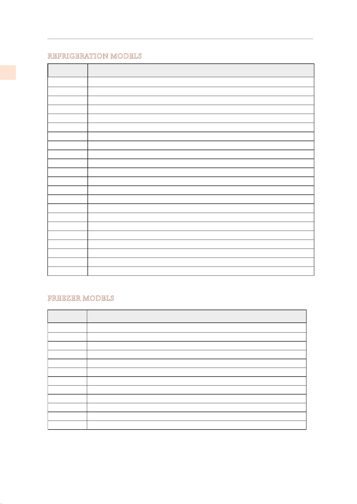
MODEL NUMBERS
KFCL30-XX Freezer Column, Color, Left Hinged, 30"
REFRIGERATION MODELS
EN
Model Description
KRPR36 Bottom Mount Refrigerator, Top Compressor, Pro, Right Hinged, 36"
KRPL36 Bottom Mount Refrigerator, Top Compressor, Pro, Left Hinged, 36"
KRPR36-XX Bottom Mount Refrigerator, Top Compressor, Pro, Color, Right Hinged, 36"
KRPL36-XX Bottom Mount Refrigerator, Top Compressor, Pro, Color, Left Hinged, 36"
KRBR36 Bottom Mount Refrigerator, Bottom Compressor, Right Hinged, 36"
KRBL36 Bottom Mount Refrigerator, Bottom Compressor, Left Hinged, 36"
KRBR36-OV Bottom Mount Refrigerator, Bottom Compressor, Overlay, Right Hinged, 36"
KRBL36-OV Bottom Mount Refrigerator, Bottom Compressor, Overlay, Left Hinged, 36"
KRBR36-XX Bottom Mount Refrigerator, Bottom Compressor, Color, Right Hinged, 36"
KRBL36-XX Bottom Mount Refrigerator, Bottom Compressor, Color, Left Hinged, 36"
KRCR24 Refrigerator Column, Right Hinged, 24"
KRCL24 Refrigerator Column, Left Hinged, 24"
KRCR24-OV Refrigerator Column, Overlay, Right Hinged, 24"
KRCL24-OV Refrigerator Column, Overlay, Left Hinged, 24"
KRCR24-XX Refrigerator Column, Color, Right Hinged, 24"
KRCL24-XX Refrigerator Column, Color, Left Hinged, 24"
KRCR30 Refrigerator Column, Right Hinged, 30"
KRCL30 Refrigerator Column, Left Hinged, 30"
KRCR30-OV Refrigerator Column, Overlay, Right Hinged, 30"
KRCL30-OV Refrigerator Column, Overlay, Left Hinged, 30"
KRCR30-XX Refrigerator Column, Color, Right Hinged, 30"
KRCL30-XX Refrigerator Column, Color, Left Hinged, 30"
FREEZER MODELS
Model Description
KFCR24 Freezer Column, Right Hinged, 24"
KFCL24 Freezer Column, Left Hinged, 24"
KFCR24-OV Freezer Column, Overlay, Right Hinged, 24"
KFCL24-OV Freezer Column, Overlay, Left Hinged, 24"
KFCR24-XX Freezer Column, Color, Right Hinged, 24"
KFCL24-XX Freezer Column, Color, Left Hinged, 24"
KFCR30 Freezer Column, Right Hinged, 30"
KFCL30 Freezer Column, Left Hinged, 30"
KFCR30-OV Freezer Column, Overlay, Right Hinged, 30"
KFCL30-OV Freezer Column, Overlay, Left Hinged, 30"
KFCR30-XX Freezer Column, Color, Right Hinged, 30"
©2019 Hestan Commercial Corporation
2
Page 5
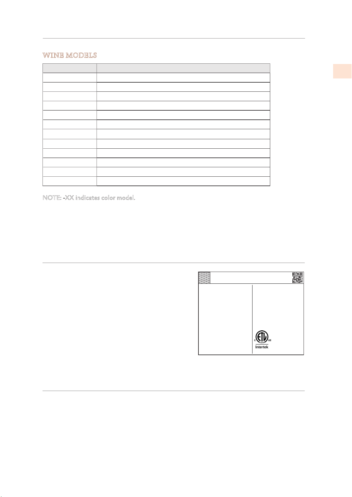
MODEL NUMBERS
WINE MODELS
(CONT.)
Model No. Description
KWCR24 Wine Column, Right Hinged, 24"
KWCL24 Wine Column, Left Hinged, 24"
KWCR24-OV Wine Column, Overlay, Right Hinged, 24"
KWCL24-OV Wine Column, Overlay, Left Hinged, 24"
KWCR24-XX Wine Column, Color, Right Hinged, 24"
KWCL24-XX Wine Column, Color, Left Hinged, 24"
KRWR24
Refrigerator with Wine, Right Hinged, 24"
KRWL24 Refrigerator with Wine, Left Hinged, 24"
KRWR24-OV Refrigerator with Wine, Overlay, Right Hinged, 24"
KRWL24-OV Refrigerator with Wine, Overlay, Left Hinged, 24"
KRWR24-XX Refrigerator with Wine, Color, Right Hinged, 24"
KRWL24-XX Refrigerator with Wine, Color, Left Hinged, 24"
NOTE: -XX indicates color model.
-BK for Stealth - Black -WH for Froth - White -RD for Matador - Red
-YW for Sol - Yellow -OR for Citra - Orange -BG for Tin Roof - Burgundy
-PP for Lush - Purple -BU for Prince - Blue -GR for Grove - Green
-GG for Pacific Fog - Graphite Gray -TQ for Bora Bora – Turquoise
EN
RATING LABEL
The rating label contains important information
about your Hestan appliance such as the model, serial
number, and electrical rating.
The rating label is located on the inside wall of the
appliance.
If service is necessary, contact Hestan Customer Care
with the model and serial number information shown
on the label.
HESTAN COMMERCIAL CORP.
ANAHEIM, CA - USA
Quantité de Gaz Réfrigerateur
Freezer Gas Fill Charge
Quantité de Gaz Congélateur
Total Absorbed Current
Courant Absorbée Totale
Voltage
Tension
Frequency
Frequence
Refrigerant Gas Type
Type de Gaz Rèfrigerant
Made in Italy
TYPICAL RATING LABEL
ozFridge Gas Fill Charge
7
MODEL
KRP36
0
CODE
1
A
FI24RC-RO
SER.NO./N° SERIE
115
V
XXXXXXXXXXX
60
Hz
R134a
3186660
ETL LISTED
CONFORMS TO
ANSI/UL STD 250
CERTIFIED TO CAN/CSA
STD C22.2 NO.63
REGULATORY / CODE REQUIREMENTS
Installation of this appliance must be made in accordance with local codes. In the absence of
local codes, this unit should be installed in accordance with the National Electrical Code and
local codes.
This appliance must be electrically grounded in accordance with local codes or in the absence
of local codes with the National Electrical Code
CSA C22.1
.
ANSI/NFPA 70
, or Canadian Electrical code
2019 Hestan Commercial Corporation
3
Page 6
IMPORTANT CHILD SAFETY
EN
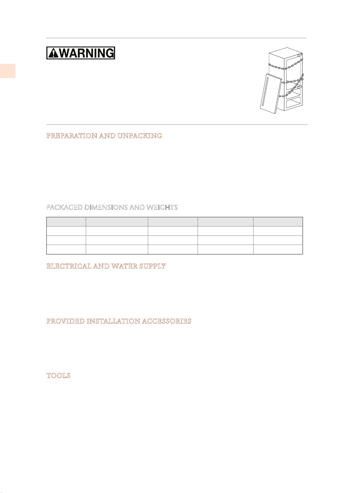
Risk of child entrapment. Before you throw away your old refrigerator or
freezer:
• Take off the doors
• Leave the shelves in place so that children may not easily climb inside.
LOCATION AND PREPARATION
PREPARATION AND UNPACKING
Before moving the refrigerator:
• Protect any finished flooring to prevent damage.
• The grille and trim pieces are packaged on the back of the unit. Handles and other items
may also be packaged on the back. Remove all such items before removing the appliance
from the pallet. See "PREPARING THE INSTALLATION" on page 10 for additional
information.
• Make sure that power can be provided to the location selected.
PACKAGED DIMENSIONS AND WEIGHTS
Width Height Depth Weight
24” Models 25-5/8” [650 mm] 89” [2260 mm] 31-1/2” [800 mm] 507 lb [230 kg]
30” Models 31-1/2” [800 mm] 89” [2260 mm] 31-1/2” [800 mm] 606 lb [275 kg]
36” Models 37-3/8” [950 mm] 89” [2260 mm] 31-1/2” [800 mm] 650 lb [295 kg]
ELECTRICAL AND WATER SUPPLY
Electrical requirement: 110V 60Hz 15a
Units with icemaker: Connect to potable water only.
Supply pressure: If using external filtration, from 7.3 to 73 PSI [0.5 - 5.0 Bar]
If using supplied water filter, from 25.4 to 73 PSI [1.75 - 5.0 Bar].
Water supply tube: 3/4” female attachment (see pg. 13 for details)
PROVIDED INSTALLATION ACCESSORIES
Customized panel mounting kit (included with -OV models only)
Anti-tip kit
Lateral/side connecting kit
See "PREPARING THE INSTALLATION" on page 10 for unpacking information.
TOOLS
The following tools are needed for the installation of the appliance:
• Phillips screw driver
• Drill and 1/8”drill bit, plus 3/8” bit for masonry
• 17mm (or 11/16”) open-end or adjustable wrench
• 13mm (or 1/2”) socket, extension, and handle
• 2.5 mm and 4mm allen wrenches
If installing two units together
• Hand rivet tool (pop rivet gun)
©2019 Hestan Commercial Corporation
4
Page 7
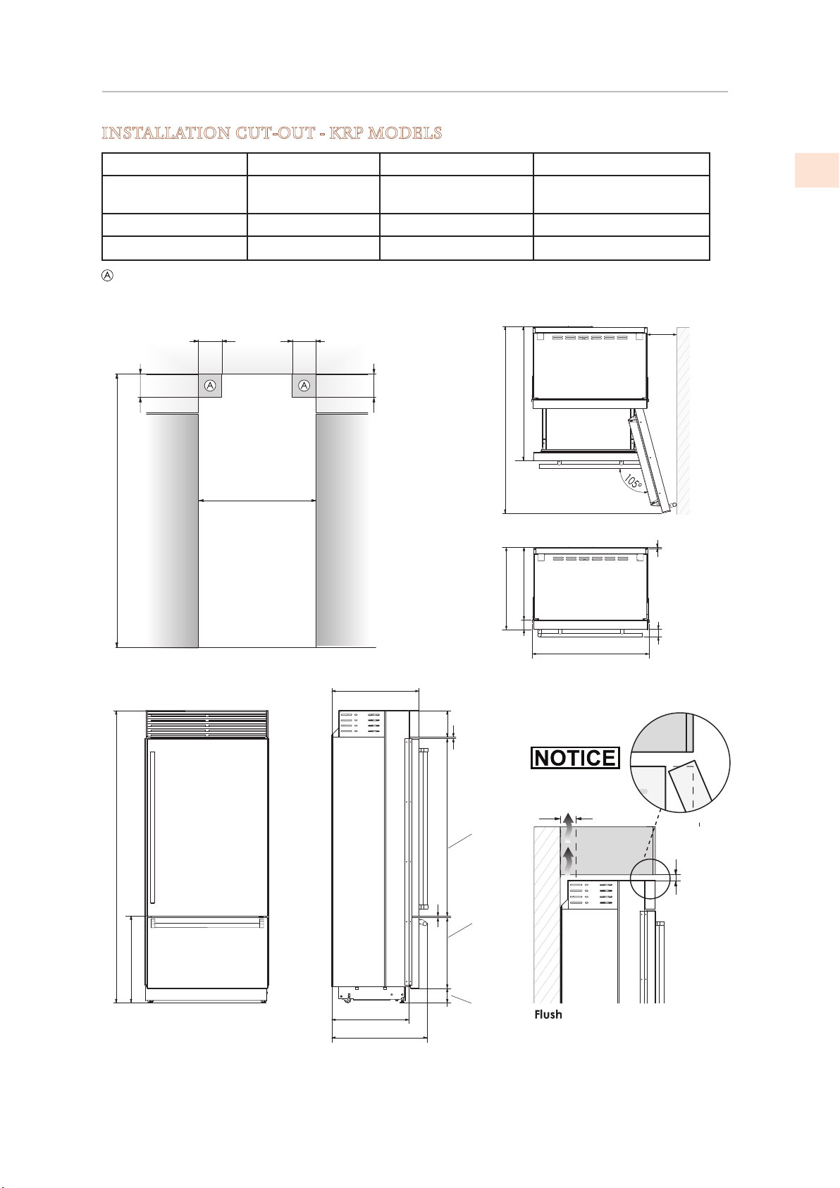
LOCATION AND PREPARATION
min 84” [2134]
83-1/2” [2120] + 1” [25]
9” [230]
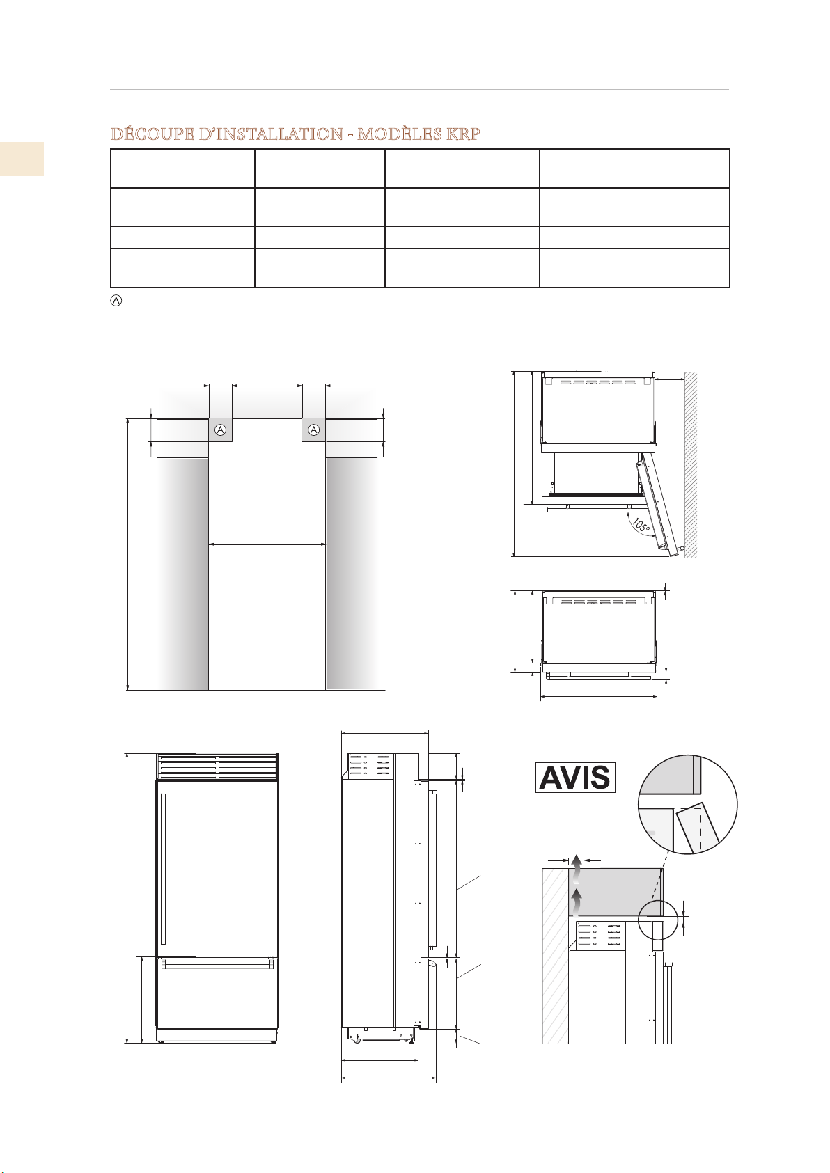
INSTALLATION CUT-OUT - KRP MODELS
(CONT.)
Cut-out Height 84” [2134] Cut-out Width 35-1/2” [900]
Door Swing
57-7/8” [1470] Door Opening Angle 105°
Clearance
Width 35-3/8” [899] Height 83-1/2” [2120] + 1” [25]
Depth with door 25” [635]
Area to be left clear for the anti-tip brackets
5-1/2” [140]
4” [100]
35-1/2” [900]
5-1/2” [140]
40” [1016]
4” [100]
57-7/8” [14 70]
EN
22” [560]
25” [635]
35-3/8” [899]
3” [75]
25” [635]
24-1/8” [613] + 1” [25]
22” [560]
27- 1/4” [693]
7-5⁄8” [195]
5⁄16” [8]
min 2” [50]
5⁄16” [8]
3-7/8” [97] 20-3/8” [516] 50” [1296]
min 3/8” [10] 2-1 /4” [58]
min 3/8” [10]
2019 Hestan Commercial Corporation
5
Page 8
LOCATION AND PREPARATION
(CONT.)
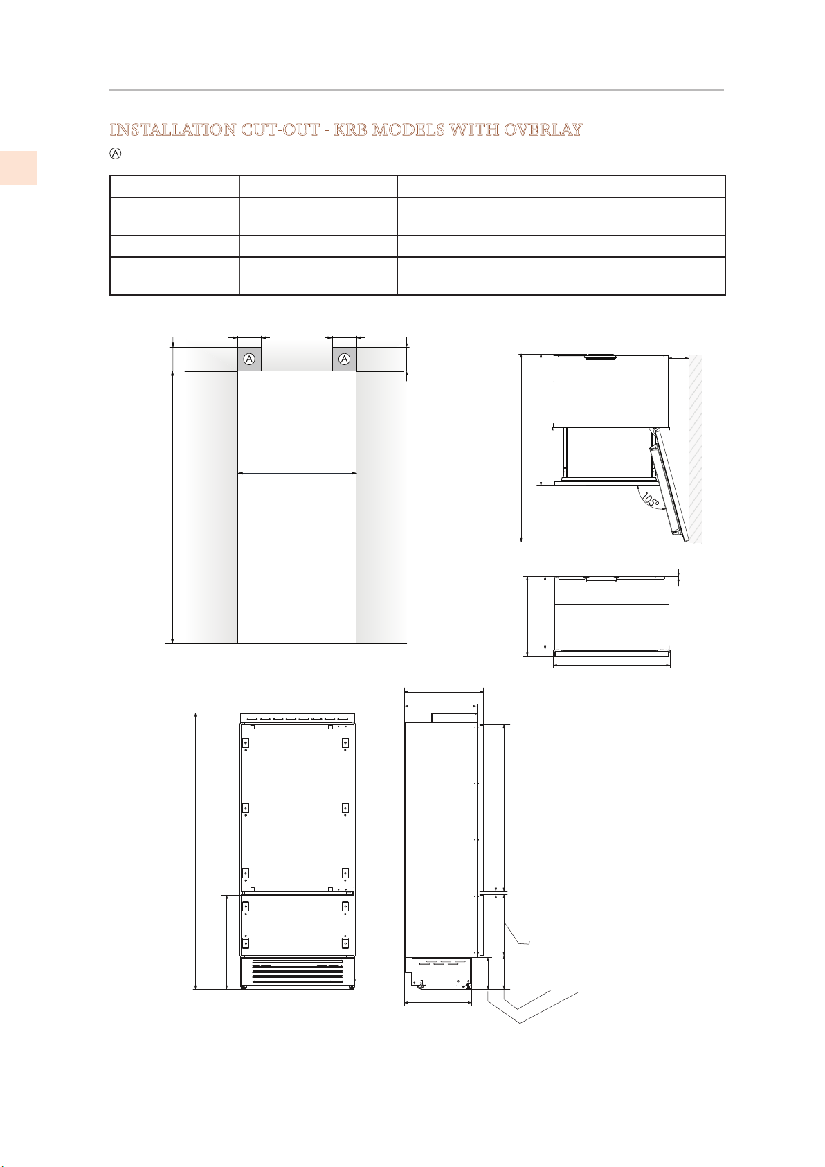
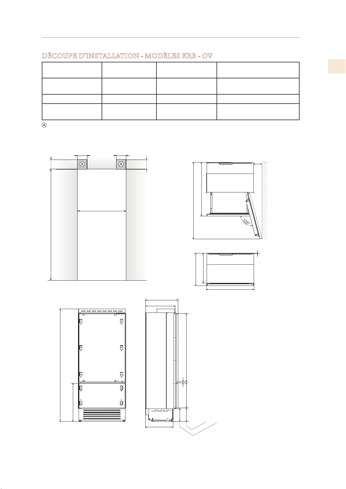
INSTALLATION CUT-OUT - KRB MODELS WITH OVERLAY
EN
Area to be left clear for the anti-tip brackets
Cut-out Height 84” [2134 mm] Cut-out Width 35-1/2” [900 mm]
Door Swing
Clearance
57-7/8” [1470 mm] Door Opening Angle 105°
Width 35-3/8” [899 mm] Height 83-1/2” [2120] + 1” [25]
Depth with door
(without panel)
4” [100 mm]
min 84” [2134 mm]
24” [610 mm]
5-1/2” [140 mm]
35-1/2” [900 mm]
5-1/2” [140 mm]
6-3/8” [160 mm]
4” [100 mm]
39” [992 mm]
36”: 57-7/8” [1470 mm]
3/8” [10 mm]
22” [560 mm]
24” [610 mm]
18-5 ⁄ 8” [474 mm]
9-3/4 “ + 1”
[248 + 25 mm]
35-3/8” [899 mm]
9-1⁄8 ” + 1”
[231 + 25 mm]
24” [610 mm]
22” [560 mm]
50-7⁄8” [1293 mm]
3/4” [20 mm]
83-1/2” + 1” [2120 + 25 mm]
3⁄8” + 1” [721 + 25 mm]
28-
19-3/4” [500 mm]
©2019 Hestan Commercial Corporation
6
Page 9
LOCATION AND PREPARATION
5-1/2” [140 mm]
5-1/2” [140 mm]
4” [100 mm]
4” [100 mm]
min 84” [2134 mm]
83- ½” [2120 ] + 1” [25]
25” [635]
57- 7⁄8” [1470 ]
2-
9” [230]
(CONT.)
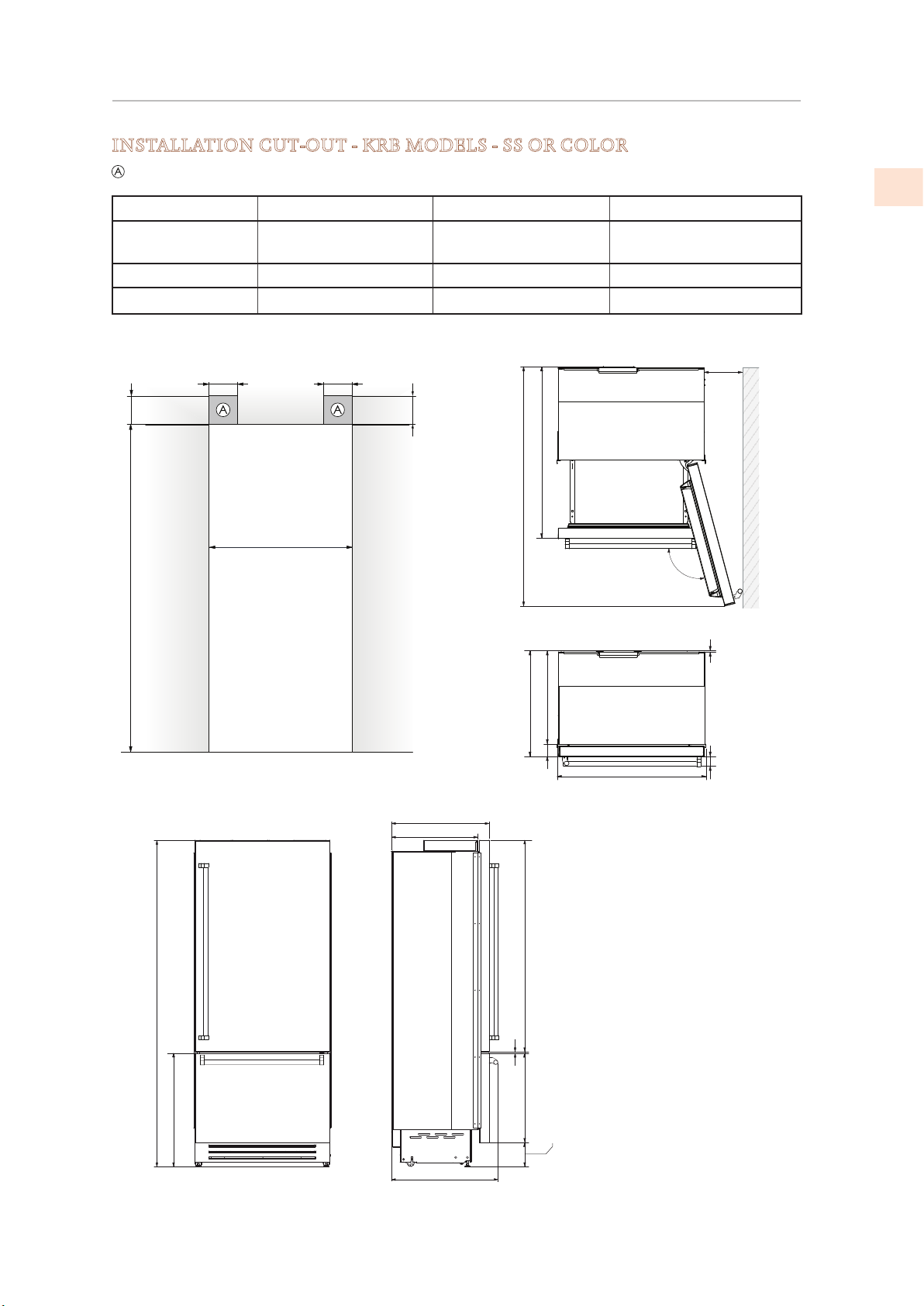
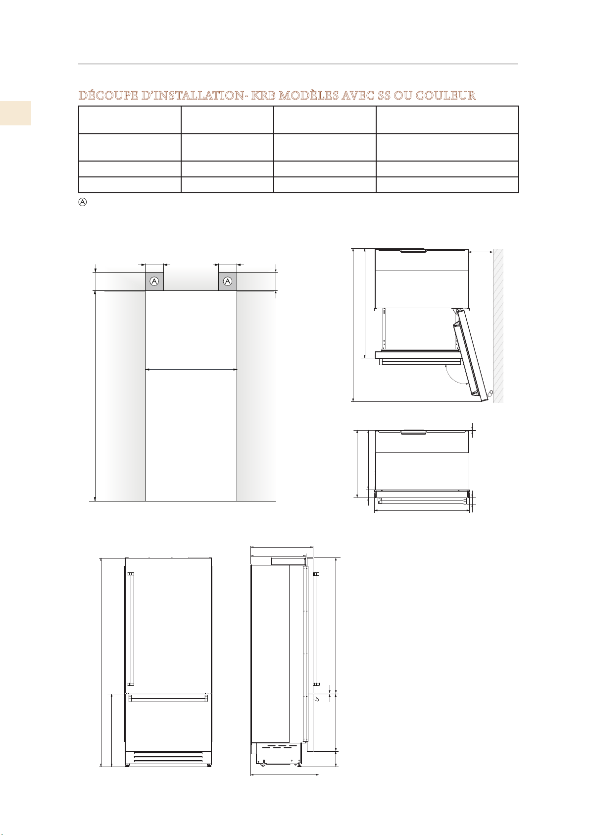
INSTALLATION CUT-OUT - KRB MODELS - SS OR COLOR
Area to be left clear for the anti-tip brackets
Cut-out Height 84” [2134 mm] Cut-out Width 35-1/2” [900 mm]
Door Swing
Clearance
57-7/8” [1470 mm] Door Opening Angle 105°
Width 35-3/8” [899 mm] Height 83-1/2” [2120] + 1” [25]
Depth with door 25” [635 ]
40” [1016 ]
35-1/2” [900 mm]
105°
EN
⁄” [732] + 1” [25]
28-
3⁄8” [10]
22” [560]
25” [635]
¾” [146] + 1” [25]
5-
35- 3⁄8” [899]
¼” [58]
3” [75]
22” [560]
27- ¼” [693]
54 ¼” [1378]23- ⁄” [587]
⁄” [9]
2019 Hestan Commercial Corporation
7
Page 10
LOCATION AND PREPARATION
5-½” [140]
4” [100]
min 84” [2134]
24”: 23-3/4” [600]
30”: 29-5/8” [750]
5-½” [140]
4” [100]
30”: 52-1/8” [1325]
24”: 46-1/4” [1175]
30”: 2-1⁄8” [53]
24”: 1-1⁄16” [27]
22-1/4” [560]
24” 1/4 [615]
3⁄8” [10]
30”: 29-1/2” [749]
24”: 23-5/8” [599]
105°
19-¾” [505]
9-1⁄8” [231] + 1” [25]
9-¼” [233] + 1” [25]
71-¼” [1808]
24-1/4” [615]
22-1/4” [560]
83-½” [2120] + 1” [25]
Area to be left clear for the anti-tip brackets
(CONT.)
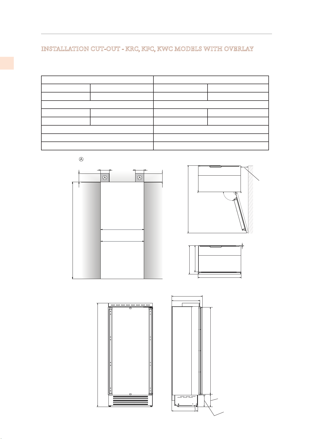
INSTALLATION CUT-OUT - KRC, KFC, KWC MODELS WITH OVERLAY
EN
24” AND 30” COLUMN REFRIGERATORS AND FREEZERS
24” WINE COLUMN AND 24” REFRIGERATOR WITH WINE
Cut-out Height Cut-out Width
24” models 84” [2134 mm] 24” models 23-3/4” [600 mm]
30” models 84” [2134 mm] 30” models 29-5/8” [750 mm]
Door Swing Clearance Width
24” models 46-1/4” [1175 mm] 24” models 23-5/8” [599 mm]
30” models 52-1/8” [1325 mm] 30” models 29-1/2” [749 mm]
Door Opening Angle 105°
Height 83-1/2” [2120 mm] + 1” [25 mm]
Depth with door (without panel) 24-1/4” [615 mm]
©2019 Hestan Commercial Corporation
8
Page 11
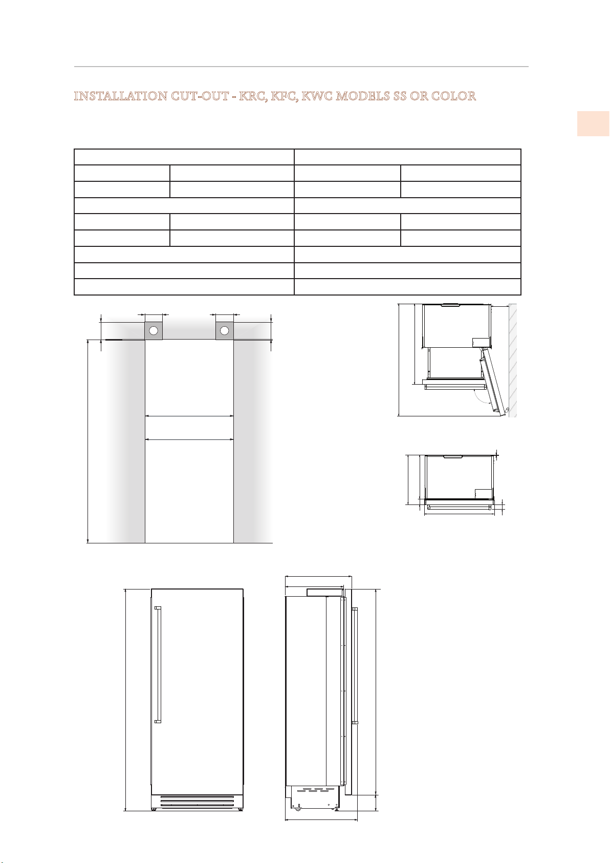
LOCATION AND PREPARATION
5-½” [140]
min 84” [2134]
4” [100]
5-½” [140]
83-½” [2120 ] + 1” [25]
25-
¼” [640]
+ 1” [25]
30: 52-⁄" [1325]
30: 7-¾" [195]
(CONT.)
INSTALLATION CUT-OUT - KRC, KFC, KWC MODELS SS OR COLOR
24” AND 30” COLUMN REFRIGERATORS AND FREEZERS
24” WINE COLUMN AND 24” REFRIGERATOR WITH WINE
Cut-out Height Cut-out Width
24” models 84” [2134 mm] 24” models 23-3/4” [600 mm]
30” models 84” [2134 mm] 30” models 29-5/8” [750 mm]
Door Swing Clearance Width
24” models 46-1/4” [1175 mm] 24” models 23-5/8” [599 mm]
30” models 52-1/8” [1325 mm] 30” models 29-1/2” [749 mm]
Door Opening Angle 105°
Height 83-1/2” [2120 mm] + 1” [25 mm]
Depth with door (without panel) 24-1/4” [615 mm]
4” [100]
A A
40-¼" [1021]
24: 46-¼" [1175]
105°
30: 29-⁄” [750]
EN
24: 6-¼" [160]
24: 23-¾” [600]
22-
¼” [565]
77-¾” [1974]
22-¼" [565]
25-¼" [640]
30: 29- 1/2" [749]
3" [75]
24: 23- 5/8" [599]
⁄" [ 10]
2-¼" [58]
27
½” [
698 ]
5-¾” [146]
2019 Hestan Commercial Corporation
9
Page 12
2
1
4
1
3
LOCATION AND PREPARATION
PREPARING THE INSTALLATION
(CONT.)
EN
Transport to installation site and unpacking
Since this is a large and heavy appliance, before transporting the appliance, check the access to
the location where it will be installed (door size, maneuvering space in stairwells, etc.).
The side trim, door handles (non OV models), grill, and possibly other items will be packaged
on the back of the appliance. Be sure to remove those items and related packaging before
attempting to remove appliance from pallet.
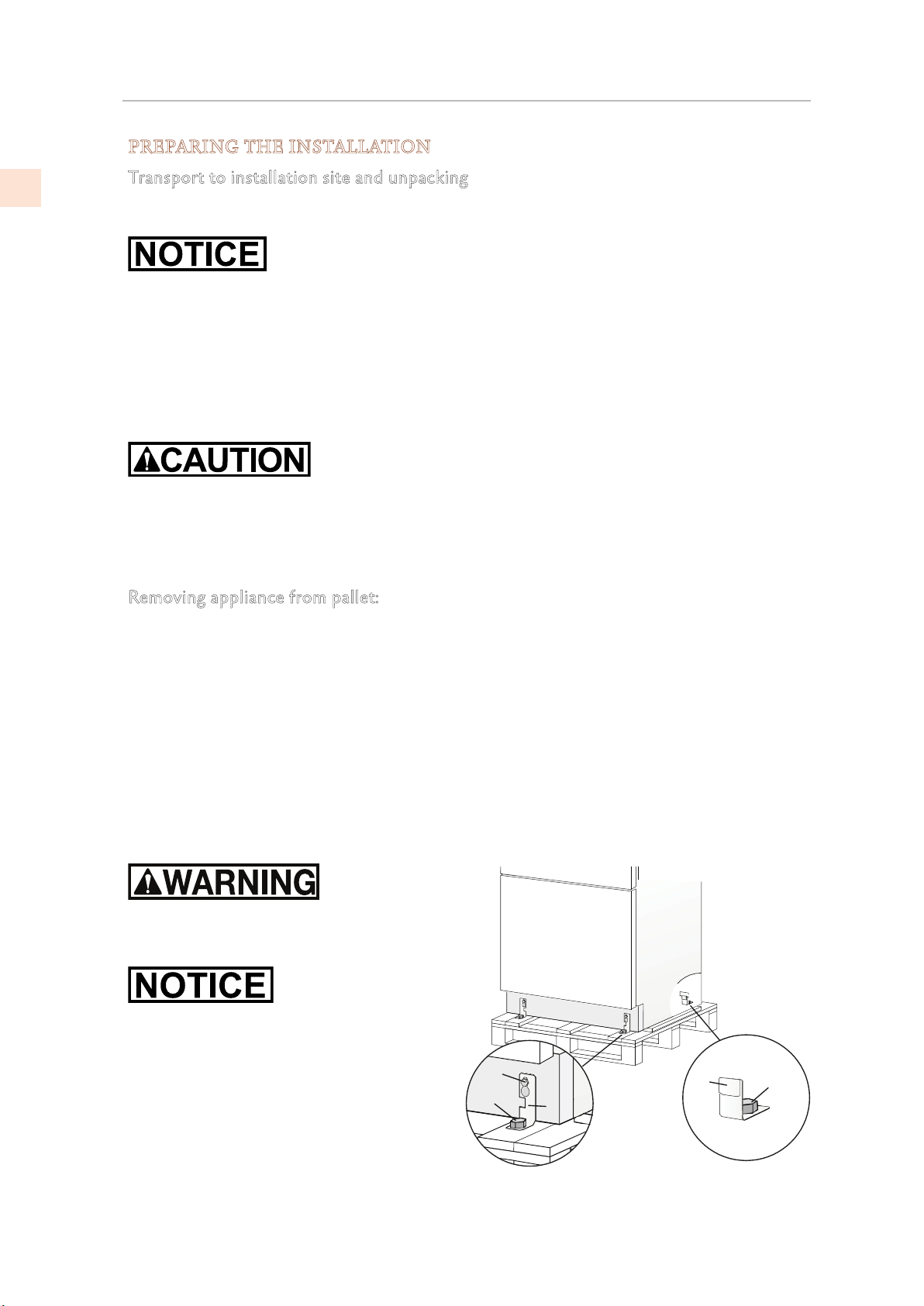
The appliance is attached to the base of the packaging (pallet) through four bolts which can
be removed using a 17 mm (11/16”) wrench.
It is recommended to use a pallet jack or other transporting device to move the appliance to
the installation site, and only at this point to remove the base of the packaging.
The appliance should always be transported in a vertical position. If this is not possible,
transport the appliance laying on its rear side.
Once at the installation site, the appliance, which is equipped with four wheels, can be taken
off the pallet and positioned in the installation area.
Removing appliance from pallet:
1) Take off the four bolts securing the appliance to the pallet by means of a 17 mm
(11/16")wrench.
2) Remove the rear hold down brackets .
3) To remove the front fixing brackets , unscrew the rear wheel adjusting bolts one or
two turns using a 13 mm wrench. This will release the front fixing brackets so you can
remove them.
4) From the back of the unit and by means of a suitable, heavy-duty hand truck, remove the
appliance and place it on the floor.
Be very careful to avoid any damage to floors. Delicate floors should be protected with
plywood, hard cardboard or similar.
The appliance is very heavy.
Take great care during handling to avoid injury.
The appliance should always be transported in
a vertical position.
Avoid at all costs leaning it on its front side.
10
©2019 Hestan Commercial Corporation
Page 13
A A
B
LOCATION AND PREPARATION
Additional included items
(CONT.)
Several items are shipped inside the appliance. These include:
• Manuals
• Panels installation hardware (-OV models)
• Water connection fitting, water filter (models with ice maker)
• Anti-tip brackets
• Care items - polishing cloth and/or sponge.
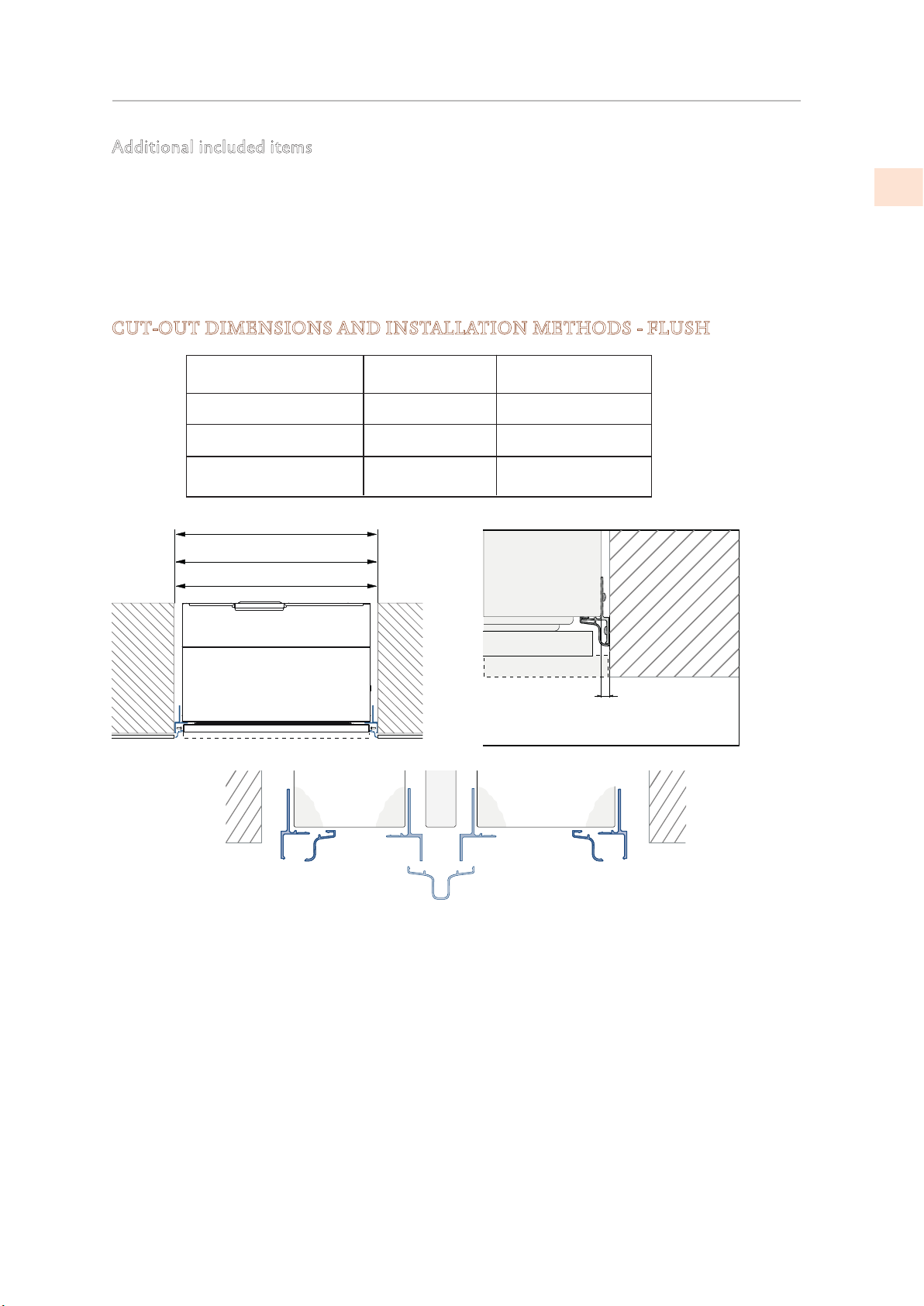
CUT-OUT DIMENSIONS AND INSTALLATION METHODS - FLUSH
Models
KRB36 Models
30” Columns (KxCx30)
24” Columns and Wine
(KxCx24, KRWx24)
36”: 35-1/2” [900 ]
30”: 29-5/8” [750]
24”: 23-3/4” [600]
Cut-out
35-1/2” [900 mm]
29-5/8” [750 mm]
23-3/4” [600 mm]
Panel Width
35-1/4” [897 mm]
29-3⁄8” [747 mm]
23-1/2” [597 mm]
A
EN
1/4” [6.5]
C
A Lateral/side connection kit (included accessory)
AKRLJK (for KRB, KRC, KFC, KWC and KRW Models)
AKRLJKP (for KRP Models)
B Central connection kit, required when joining 2 units
(not included - must be ordered as a separate accessory)
AKRCJK-OV for KRB, KRC, KFC, KWC and KRW Models with overlay front
AKRCJK for KRB, KRC, KFC, KWC and KRW Models with stainless or colored front
AKRCJKP for KRP Models
C Anti-Condensation kit # AKRACPP, required when joining two KRP units.
(not included - must be ordered as a separate accessory)
2019 Hestan Commercial Corporation
11
Page 14
LOCATION AND PREPARATION
A A
36: 35-1/2” [900 ]
(CONT.)
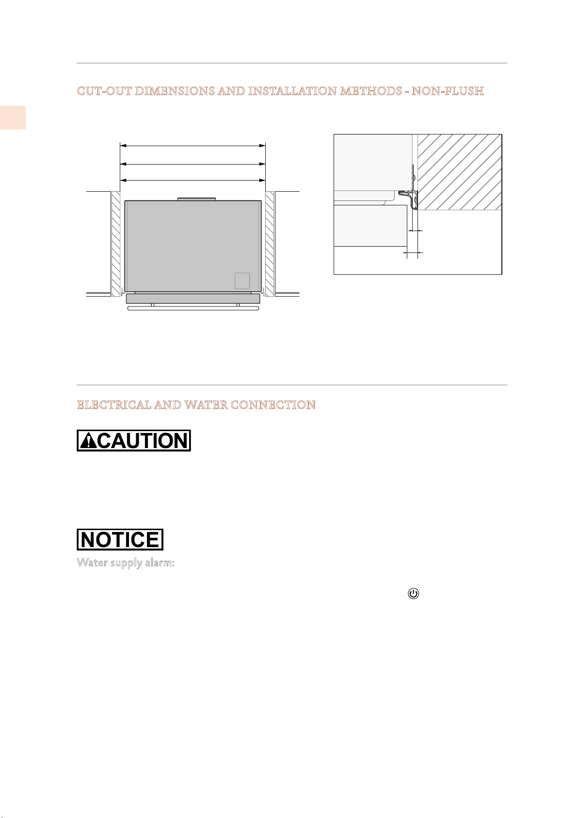
CUT-OUT DIMENSIONS AND INSTALLATION METHODS - NON-FLUSH
EN
If installing non-flush, the same side trim is used and the same cutout width is required.
30: 29-5/8” [750]
24: 23-3/4” [600 ]
A
1/4” [6 . 5]
3/8” [10]
A Lateral/side connection kit
CONNECTIONS
ELECTRICAL AND WATER CONNECTION
Do not use extension cords and/or multiple adapters for the power supply connection.
Do not use extension cords or adapters.
The built-in Hestan filter cannot make any water safe to drink, it must be used with water that
is already suitable for human consumption.
Water supply alarm:
If the water supply must be turned off after the the appliance is fully installed, connected to
the water supply (if applicable) and operational, touch the On/Off switch
off first to avoid a ‘NO WATER IN’ alarm.
to turn the unit
12
©2019 Hestan Commercial Corporation
Page 15
CONNECTIONS
E
E
(CONT.)
The appliances are delivered from the factory for operation at 110V-120V AC - 60Hz (US
and Canada). They are provided with a suitable supply cord and plug to be connected to an
appropriate 15A socket (US and Canada) provided with an effective grounding.
A circuit breaker should also be installed and should be easily accessible so that it can be easily
switched off before performing any installation or maintenance.
To connect to the water supply system (for appliances equipped with ice makers) a 1/4”
waterline with accessible shut-off valve must be supplied.
The appliance is provided with a water adapter elbow which is suitable for high water pressure
and complies with appropriate regulations. The water filter cartridge provided with the
appliance should be installed according to the accompanying instructions.
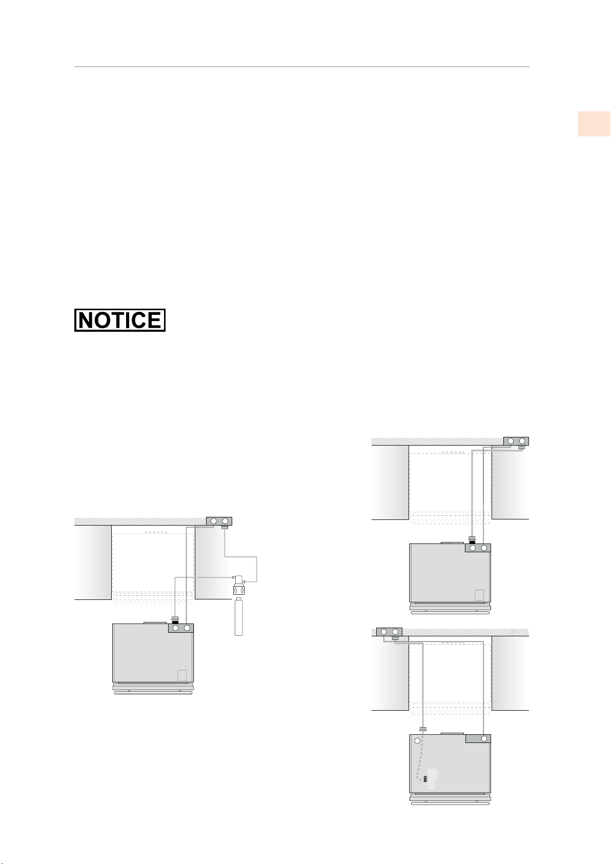
KRP, KRB models have the water filter mounted above the refrigerator compartment above the
glass panel.
KFC models are provided with a water filter assembly which must be mounted outside the
unit.
Use only the new adapter which is supplied with the appliance. The solenoid connection
on the appliance looks like 3/4” diameter but is metric threaded. A standard garden hose
threaded connector such as a braided stainless hose found at typical hardware stores will strip
or damage the solenoid threads. Use only the supplied 1/4” quick connect elbow adapter for
connecting a 1/4” copper or polyethylene source water line to the appliance.
EN
Electrical cord length: 78-3/4” [2000 mm]
Water connection line length: 98-3/8” [2500 mm]
See following page for additional information.
W
E
W
KFC models
Water filter to
mount in cabinet
W
E
W
KRB models
E
W
W
E
KRP models
Water connec-
tion in base of
unit near front
2019 Hestan Commercial Corporation
13
Page 16
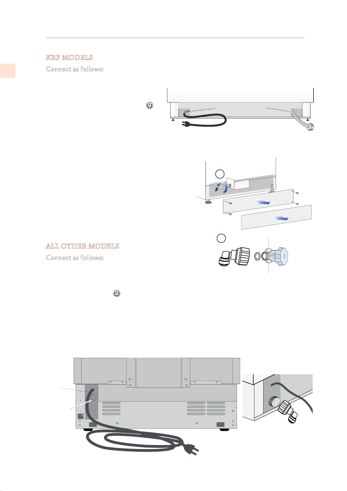
Back of appliance
Electrical
connection
Water
connection
CONNECTIONS
KRP MODELS
(CONT.)
EN
Connect as follows:
Unwind the electric cord and connect it directly to the wall socket.
Observe the information display. If the
appliance is not in Stand-by condition or
if any lights are on, press the On/Off
button for three seconds to switch it off.
Connect the water line to the threaded
connection at the base of the unit. (1)
Fit the other end of the hose (2) to the water valve, use the gaskets provided in the Owner’s
Kit.
Firmly tighten by hand - a tool/wrench should not be
needed to make a proper seal.
Turn on the water and ensure all connections are not
leaking prior to pushing the unit into the opening.
Back of appliance
Water connectionElectrical connection
Front of
appliance
1
2
ALL OTHER MODELS
Connect as follows:
Unwind the electric cord and connect it directly to the
wall socket.
Observe the information display. If the appliance is not in Stand-by condition or if any lights
are on, press the On/Off
Push the 1/4” source waterline fully into the elbow connector then thread the elbow adapter
to the solenoid at the back of the appliance.
Firmly tighten by hand - a tool or wrench should not be needed to make a proper seal.
Turn on the water and ensure all connections are not leaking prior to pushing the unit into the
niche.
button to switch it off.
14
©2019 Hestan Commercial Corporation
Page 17
OVERLAY PANELS
DOOR AND DRAWER OVERLAY PANEL PREPARATION
Decorative panels:
The dimensions of the panels are indicated in the table
and drawings on following pages.
To align panels with other kitchen structures, sizes
can be adjusted if the door panel needs to be higher
than the upper edge of the refrigerator door, and/or
the drawer panel needs to lower than the edge of the
drawer.
The panels must be mounted using special braces which
attach to adjustable devices provided on the door and
drawer and with brackets that anchor and adjust the
panel’s vertical direction.
Braces, brackets and fixing screws are provided with
the appliance and must be applied to the panel as
indicated.
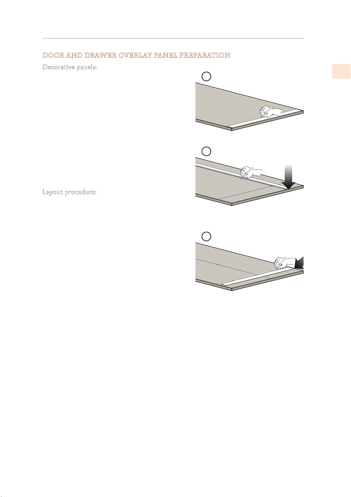
Layout procedure:
To prepare the panels to be mounted on the appliance,
follow these steps, working on the back of the panel.
Door Panel
1) Trace a line dividing the panel width in half. (1)
2) Starting from the bottom edge of the panel, mark
the positioning of the brackets. (2)
1
EN
2
3
3) Following the corresponding table, mark the
external and then the internal hole. (3)
2019 Hestan Commercial Corporation
15
Page 18
OVERLAY PANELS
(CONT.)
DOOR AND DRAWER OVERLAY PANEL PREPARATION (continued)
EN
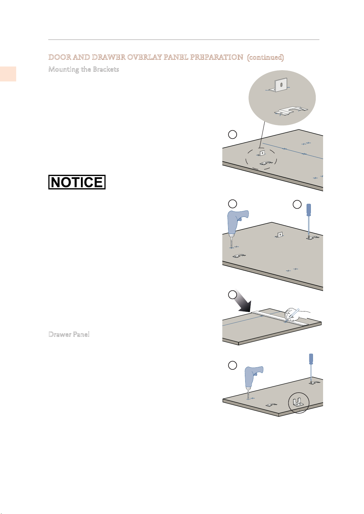
Mounting the Brackets
4) Position the brackets on each set of marks to make sure
they are aligned. (4)
Note that the support bracket mounts with its flange
toward the top of the door.
• If necessary, drill starter holes in the panel. (5)
(Use a drill stop to avoid drilling through or damaging
the finish surface.)
The installation kit includes 5/8” screws. If the panel isn’t
substantially thicker than 5/8”, you’ll need shorter screws.
4
5
6
1) Screw the brackets in place. (6)
Drawer Panel
When preparing the Drawer Panel, follow the same
instructions as per the door panel, but make sure
measurements are taken starting from the top edge. (7)
The support bracket faces the opposite way from the door
panel bracket. (Compare images 4 and 8.)
7
8
16
©2019 Hestan Commercial Corporation
Page 19
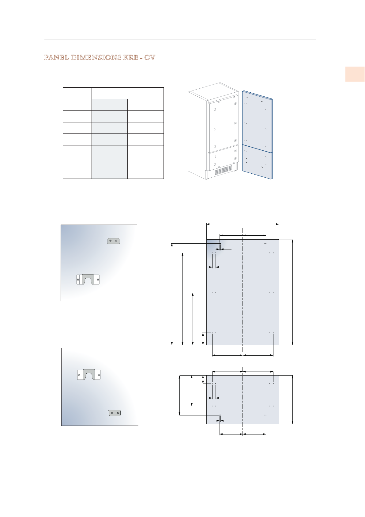
OVERLAY PANELS
(CONT.)
PANEL DIMENSIONS KRB - OV
KRB36-OV
EN
A
B
C
D
E
F / G
Hinge Left
Hinge Right
35-1/4” [897 ] 35-1/4” [897]
14” [355.5]
10-1/4” [261]
16-1/2” [418 ]
10-1/4” [261]
14” [355.5]
15-1/4” [386]
15-1/4” [386] 16-1/2” [418]
14” [354.5] 14” [354.5]
3
1-
½” [13]
⁄
” [34]
8
A
B C
1285]
” [
8
⁄
5
50-
45- ¾” [1163]
20” [507.5]
[660]
26”
[382]
”
8
⁄
1
15-
¼” [157]
6-
4” [100]
D E
D E
3
⁄
” [34]
1-
8
½”[13]
F G
min 54-3/4” [1390]
[635]
max 25”
2019 Hestan Commercial Corporation
17
Page 20
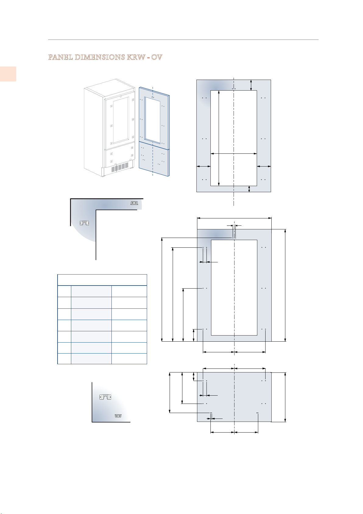
EN
OVERLAY PANELS
(CONT.)
PANEL DIMENSIONS KRW - OV
3
5-
[135]
7
7-
⁄
”
8
<
[200]
”
8
⁄
3
42-
[1075]
12-7⁄8”
⁄
[327]
”
8
5-
3
⁄
”
8
[135]
4-
½” [115]
KRWx24-OV MODELS
Hinge Left
A
23-½” [597]
D
E
F / G
H
I
7
⁄
” [276.5]
10-
8
3
⁄
” [236.5]
9
8
8” [203.5]
5
10-
⁄
” [270.5]
8
1
9-
⁄
” [230.5]
8
Hinge Right
23-½” [597]
3
9-
⁄
” [236.5]
8
7
⁄
” [276.5]
10-
8
8” [203.5]
1
9-
⁄
” [230.5]
8
5
⁄
” [270.5]
10-
8
[1286]
”
8
⁄
5
50-
20” [507.5]
[1152.5]
”
8
⁄
3
45-
[650.5]
”
8
⁄
5
25-
[382]
”
8
⁄
1
15-
[148.5]
”
8
⁄
7
5-
4” [100]
¼” [6.5 ]
3
1-
⁄
" [34]
8
H I
D E
1-3⁄8" [34]
½” [13]
A
¼” [6.5 ]
[1390]
¾”
min 54-
max 25” [635]
18
F G
©2019 Hestan Commercial Corporation
Page 21
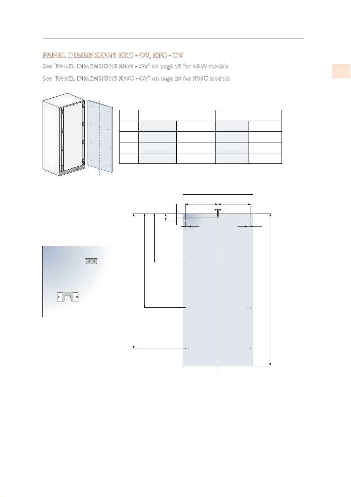
OVERLAY PANELS
(CONT.)
PANEL DIMENSIONS KRC - OV, KFC - OV
See "PANEL DIMENSIONS KRW - OV" on page 18 for KRW models.
See "PANEL DIMENSIONS KWC - OV" on page 20 for KWC models.
1
30” -OV Column Models
Hinge Left
A 23B
C
3
29-
⁄
” [747]
8
1
⁄
” [343]
13-
2
1
⁄
” [343] 13-
13-
2
” [165]
2
⁄
1
6-
” [690.5]
4
⁄
1
27-
” [112]
8
⁄
3
4-
Hinge Right
3
29-
⁄
” [747] 23-
8
1
⁄
” [343]
13-
2
1
⁄
” [343]
2
3
1-
⁄
” [34]
8
24”-OV Column Models
Hinge Left
1
7
10-
1
10-
A
B C
1-
⁄
” [597]
2
⁄
” [276.5]
8
⁄
” [268]
2
1
⁄
” [13]
2
3
⁄
” [34]
8
Hinge Right
1
⁄
” [597]
2
1
⁄
” [268]
10-
2
7
10-
⁄
” [276.5]
8
EN
” [1797]
4
⁄
3
70-
50” [1271.5]
” [1933]
8
⁄
1
min 76-
2019 Hestan Commercial Corporation
19
Page 22
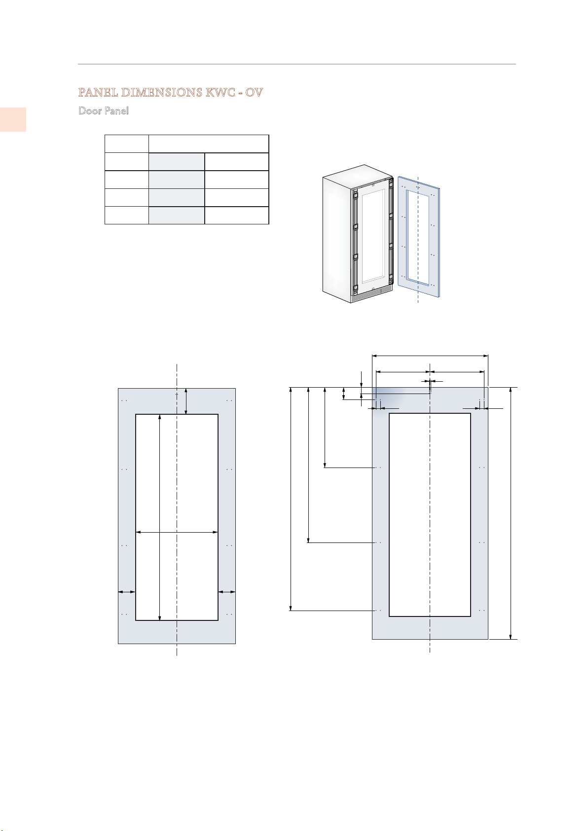
OVERLAY PANELS
(CONT.)
PANEL DIMENSIONS KWC - OV
EN
Door Panel
KWCR/L24-OV MODELS
Hinge Left
A
B
C
1
23-
⁄2” [597]
10-7⁄8" [276.5]
min 7-
Hinge Right
23-1⁄2” [597]
10-1⁄2” [268]
10-7⁄8” [276.5]10-1⁄2” [268]
7
⁄
”
8
[200]
1
B C
1
⁄
” [13]
2
A
1
⁄
” [13]
2
1
⁄
” [13]
2
3
5-
⁄
8
[135]
62” [1572]
”
24: 12-
[327]
7
⁄
”
8
3
5-
⁄
[135]
” [165]
2
” [112]
⁄
8
1
” [690.5]
4
⁄
1
⁄
3
6-
4-
27-
50” [1271.5]
” [1933]
8
⁄
” [1797]
4
⁄
3
1
70-
min 76-
”
8
20
©2019 Hestan Commercial Corporation
Page 23
OVERLAY PANELS
E
(CONT.)
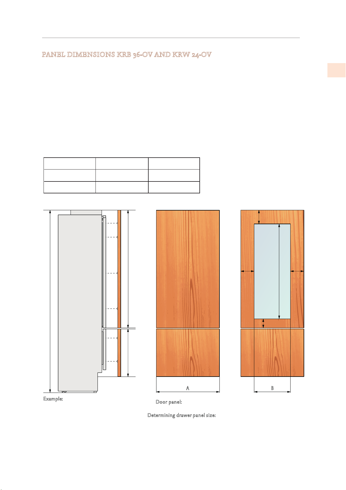
PANEL DIMENSIONS KRB 36-OV AND KRW 24-OV
Panels can have thickness ranging between 3/4” [18mm] and 1-1/8“ [28 mm].
Door panels can have a maximum weight 51 lbs [23 kg] and drawer panels may be a maximum
weight of 25 lbs [11kg].
Exceeding these weights could void your warranty for any service issues which can be
attributed to overweight panels.
The hinge mechanism on Hestan refrigerators is considered to be `Zero-clearance`. The door
and drawer widths specified below assume the minimum niche width is being used and a 1/8”
[3.5mm] reveal is desired around the panels. Adjust your panel dimensions accordingly to your
own design criteria considering your niche width and your reveal. Minimum reveal / gap should
not be less than 1/16” [1.5mm].
Models
KRBR/L36-OV
KRWR/L24-OV
Door/Drawer Width A
35-1/4” [897]
Door Cutout Width B
N/A
12-7/8” [327]23-1/2” [597]
min 7-7/8” [200]
EN
5-3/8”
[135]
54-3/4” [1390]
1/8” [3]
83-1/2” [2121] + 1” [25]
max 25” [635 ]
min 21-1/4” [540]
A B
xample:
84” cut-out height 36” cut-out width
4” toe kick height
1/8” gap desired all around
oor panel:
D
D
etermining drawer p
Width: 35-3/4”
Height: 84” − 1/8” − 54-3/4” − 1/8” − 4” = 25”
If you want a 6” toe kick height with 1/8" gaps then your
bottom drawer panel height would be 23”
Width: 35-3/4”
Height: 54-3/4”
anel size:
4-1/2” [115]
5-3/8”
[135]
42-3/8” [1075]
2019 Hestan Commercial Corporation
21
Page 24
OVERLAY PANELS
(CONT.)
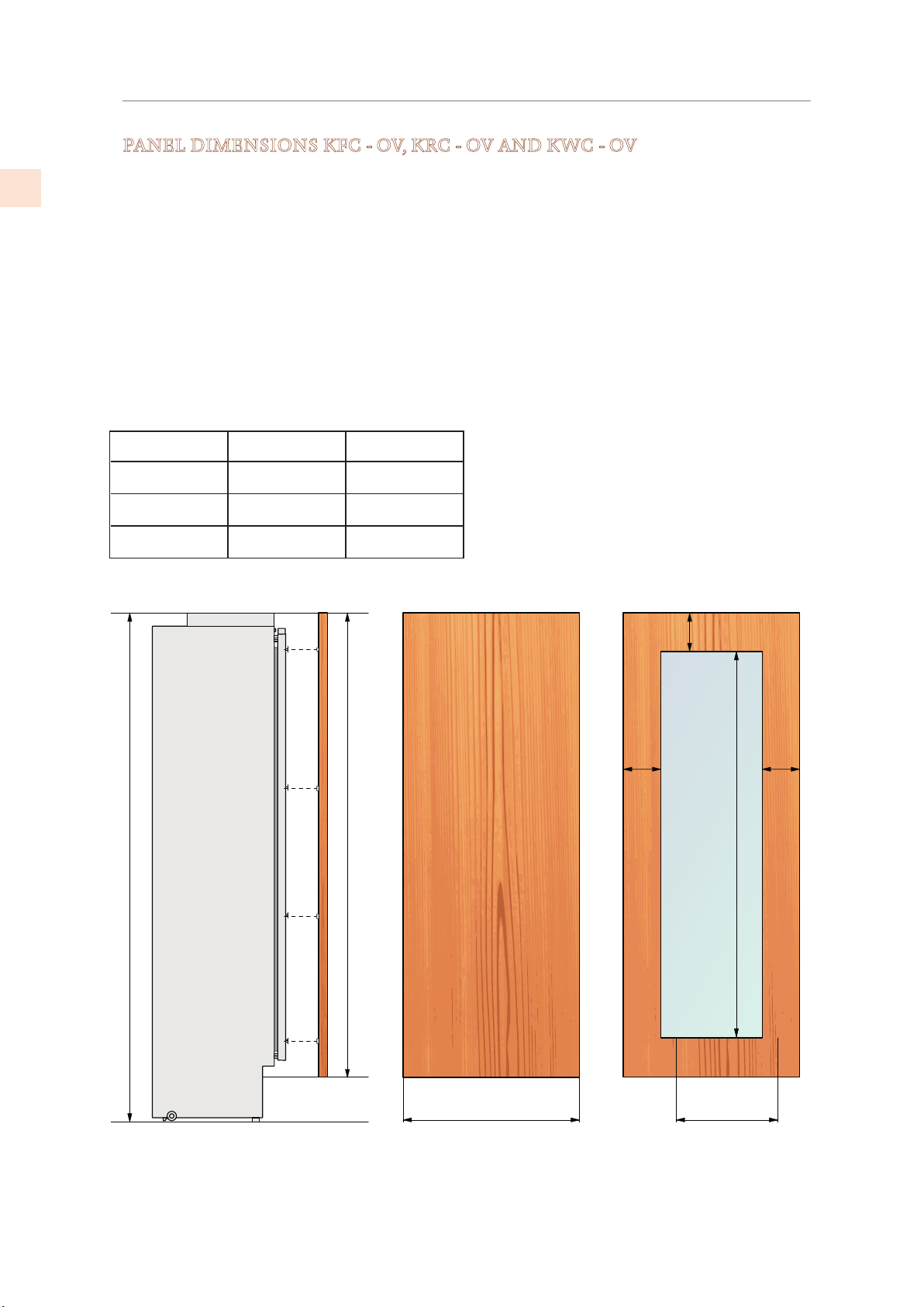
PANEL DIMENSIONS KFC - OV, KRC - OV AND KWC - OV
EN
Panels can have thickness ranging between 3/4” [18mm] and 1-1/8“ [28 mm].
Door panels can have a maximum weight 51 lbs [23 kg] and drawer panels may be a maximum
weight of 25 lbs [11kg].
Exceeding these weights could void your warranty for any service issues which can be
attributed to overweight panels.
The hinge mechanism on Hestan refrigerators is considered to be `Zero-clearance`. The door
and drawer widths specified below assume the minimum niche width is being used and a 1/8”
[3.5mm] reveal is desired around the panels. Adjust your panel dimensions accordingly to your
own design criteria considering your niche width and your reveal. Minimum reveal / gap should
not be less than 1/16” [1.5mm].
Models
KFC, KRC30-OV
KFC, KRC24-OV
KWC24-OV 23-1/2” [597]
Door/Drawer Width
A
29-3/8” [747]
23-1/2” [597]
Door Cutout Width
B
N/A
N/A
12-7/8” [327]
83-1/2” [2121] + 1” [25]
min 76-1/8” [1933]
max 79-7/8” [2028]
5-3/8”
[135]
min 7-7⁄8” [200]
5-3/8”
[135]
62” [1572 ]
22
A B
©2019 Hestan Commercial Corporation
Page 25
OVERLAY PANELS
in your panels.
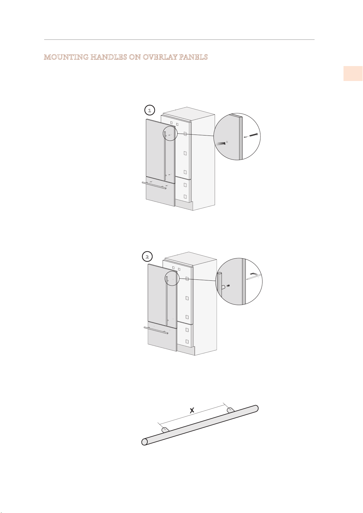
Handles must be mounted on the panels before the panels are
(CONT.)
MOUNTING HANDLES ON OVERLAY PANELS
applied to the fridge.
EN
Place the handle on top of the holes and insert the
screws through the panel and into the handle support.
1
2
Handles not provided with Overlay (-OV
(sample handle shown)
Accurately measure the distance between hole centers for
correct dimensions to apply before drilling the mounting holes
Models
)
2019 Hestan Commercial Corporation
23
Page 26
OVERLAY PANELS
adjust spacing between door
(CONT.)
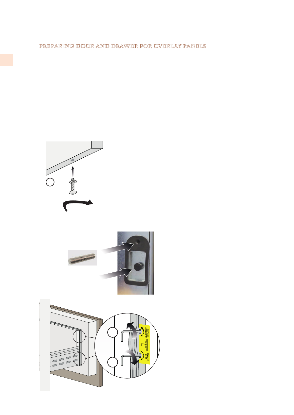
PREPARING DOOR AND DRAWER FOR OVERLAY PANELS
EN
The adjusting screws and hanger bolts must be threaded into place in the door (and drawer, if
applicable) before applying the decorative panels.
Install the vertical adjustment screws into the bottom of the drawer (if applicable) 2-3 turns
deep. The vertical adjustment screws for the door panel are installed after applying the door
panel.
Install one hanger bolt into each recess - only 2-3 turns deep.
Install one depth adjustment screw into the holes above or below each recess - the wrench
opening goes in first so adjustments can be made from the appliance side of the door. These
should be screwed in almost flush to the face of the gasket surrounding them.
The depth adjustment screws can be started and screwed in much of the way by hand. If
needed, they can be finished using a 4mm allen wrench from the inside of the door or drawer gently pull the door gasket aside to reveal the screw hole.
NOTE: Vertical adjustment
Location of vertical
adjustment screws in
1
drawer
Vertical adjustment screw
screws for door are installed
after hanging panel on door
Depth adjustment screw:
Install with socket toward
appliance
Hanger bolt
4
5
(4) Depth adjust screws - these
and panel
(5) Hanger bolts - these
secure the panel
24
©2019 Hestan Commercial Corporation
Page 27
OVERLAY PANELS
(CONT.)
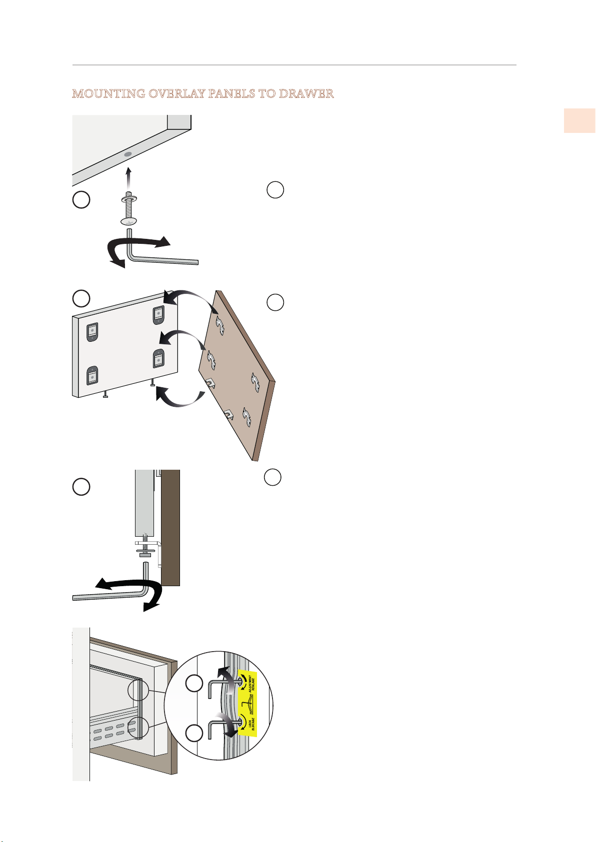
MOUNTING OVERLAY PANELS TO DRAWER
Once all brackets and small brackets have been
applied to the panels, you can begin installing
the bottom drawer panel.
Leave the vertical adjustment screws
1
2
1
just a few turns in.
Mount the bottom drawer panel: Make
2
sure the height adjustment screw heads are
under the adjusting brackets. Then fit the
attachment brackets over the hanger bolts.
Final adjustment must be done after the
appliance is in place and the side trim mounted.
EN
Use the height adjustment screws to align panels
3
4
5
3
to adjacent cabinets.
The panel has some adjustment sideways when
the hanger bolts are slightly loose.
Depth alignment: working from the inside of
the drawer, use the depth adjusting screws
(4) to push the panel away from the door as
needed, and snug the hanger bolts (5) to
secure the panel in place.
2019 Hestan Commercial Corporation
25
Page 28
OVERLAY PANELS
(CONT.)
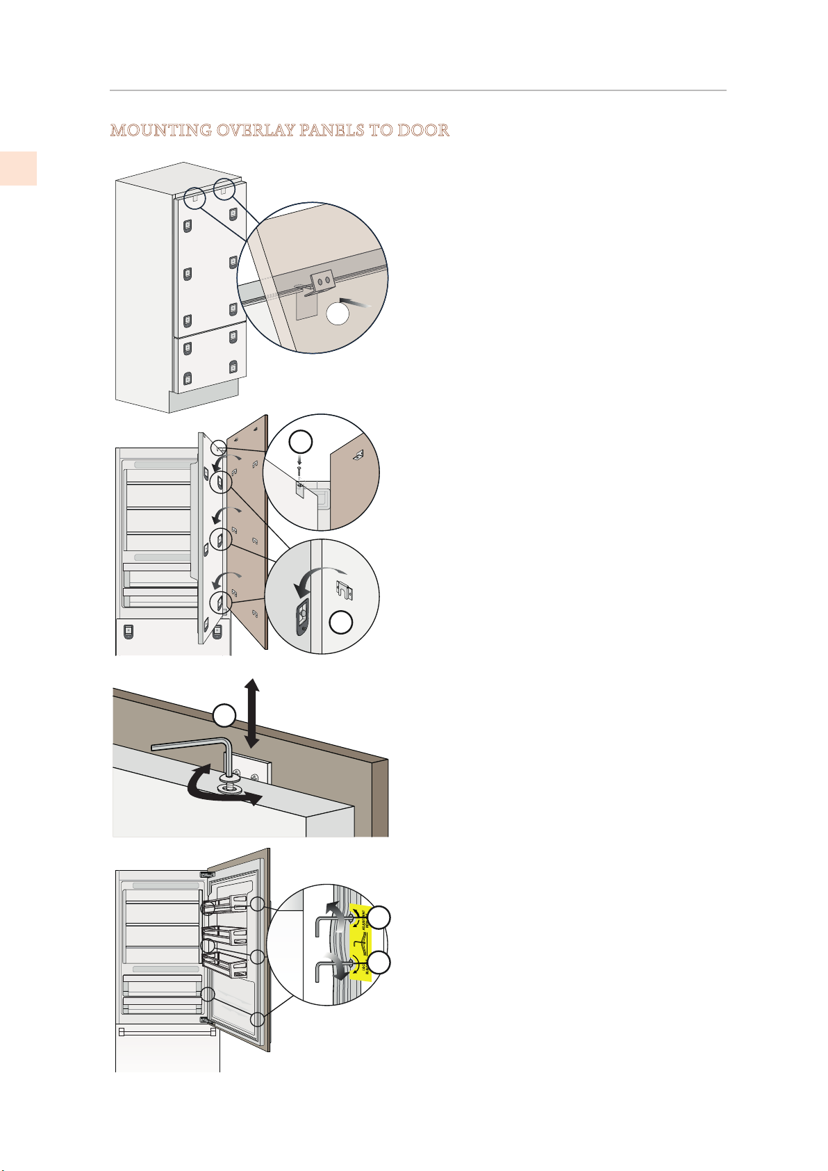
MOUNTING OVERLAY PANELS TO DOOR
EN
Hook the panel to the hanger bolts starting
from the top aligning brackets
After the panel is hooked on all hanger
bolts, install the two vertical adjustment
6
7
screws.
See
(9) below.
At this point, alignment between the
panel and adjacent cabinets can be
adjusted using the alignment brackets and
brackets (7) and (8).
(6).
8
Vertical alignment: tighten or loosen the screws
9
in the brackets to raise or lower the panel. (
Depth alignment: working from the inside of
the door, after lifting up the magnetic seal,
10
adjust the panel position so it is closer to or
further away from the door using (
fix the panel in position using (
11
11)
9)
10)
and then
26
©2019 Hestan Commercial Corporation
Page 29
FINAL INSTALLATION
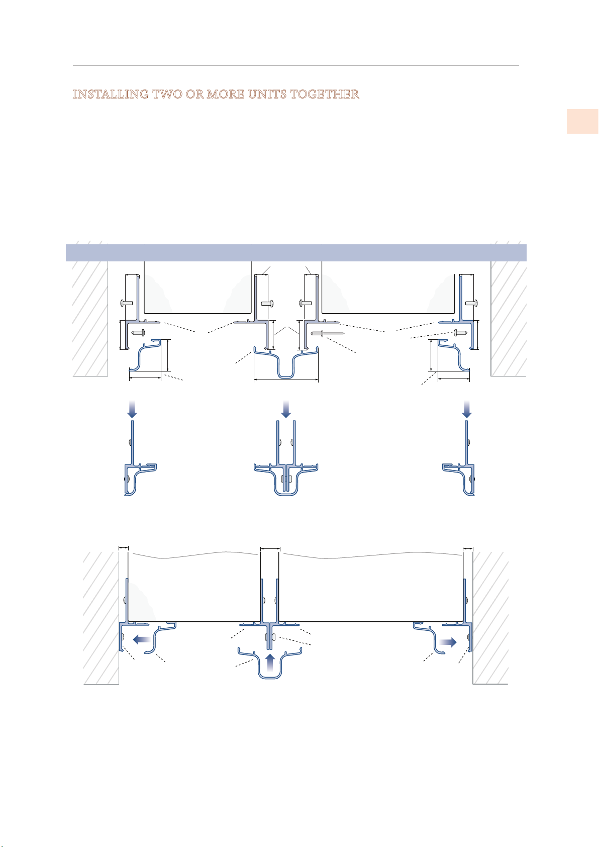
INSTALLING TWO OR MORE UNITS TOGETHER
Installing two or more units as built-ins next to each other requires a Central Connection Kit.
(Not included - must be ordered as a separate accessory)
AKRCJK (for KRB, KRC, KFC, KWC and KRW Models in Stainless Steel or color)
AKRCJK-OV (for KRB, KRC, KFC, KWC and KRW overlay models )
AKRCJKP (for KRP Models)
The appliance comes with side connectors on each side. The connector kit provides connectors
for the rear of the units, fasteners, and a trim cap for the center junction.
Side and central profile mounting
Wall
or
furniture
3/4” [20]
7/8” [22]
1/4” [6.5]
Appliance Appliance
A
7/8” [22]
B
3/4” [20]
D
C
1-3/4” [44.4]
A
E
B
1/4” [6.5]1/4” [6.5]
Wall
or
furniture
3/4” [20]
7/8” [22]
7/8” [22]
EN
Wall
or
furniture
Aluminum side connector
A
Trim cover - side
B
C
Trim cover - center
A
A
B B
A Aluminum side connector
B Trim cover - side
C
1/2” [13]
Center connector fasteners
D
E
Side connector fasteners to
cabinet - (installer/customer
provided)
ApplianceAppliance
A
D
C Trim cover - center
D
Fasteners
1/4” [6.5]1/4” [6.5]
Wall
or
furniture
A
2019 Hestan Commercial Corporation
27
Page 30
FINAL INSTALLATION
(CONT.)
EN
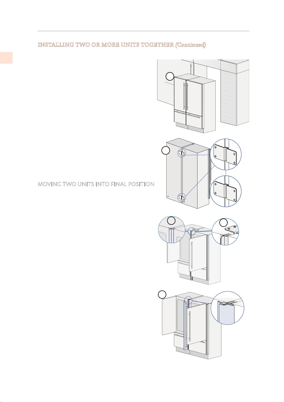
INSTALLING TWO OR MORE UNITS TOGETHER
Position the two units so that, when joined, they can be rolled into their final position.
1) For KRP units, place the anti-condensation
insulator according to its directions.
2) Place the units side by side, and check leveling.
The two units must be at the same height before
connecting. (Item 3, this page)
The side connectors should just touch along their
length.
3) At the rear, mount the joining brackets to one
unit, then the other. (Item 2, this page)
4) The top may also require a connector. Install if
required/provided. (Item 4, this page)
5) At the front, attach the aluminum center
connectors together using the fasteners provided.
(Items D, previous page)
6) Snap the center trim cover into place.
(Item 5, this page)
(Continued)
1
2
MOVING TWO UNITS INTO FINAL POSITION
Make sure the side connectors will fit the cutout
width. See “CHECK/ADJUST SIDE TRIM” on page 30.
The procedure is the same as for a single unit. See
following page.
3
5
4
28
©2019 Hestan Commercial Corporation
Page 31
FINAL INSTALLATION
(CONT.)
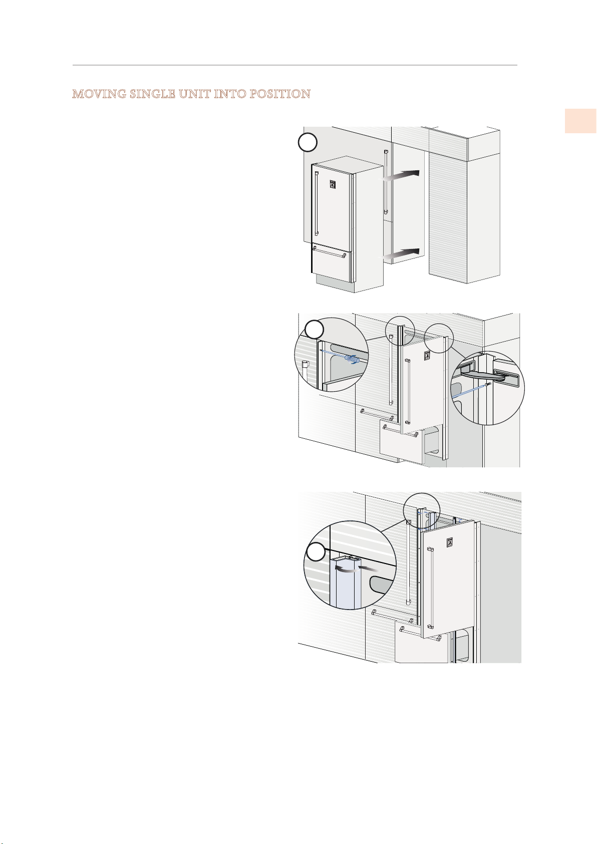
MOVING SINGLE UNIT INTO POSITION
Side connectors with decorative trim pieces are provided to secure the appliance to adjacent
cabinetry.
Make sure the side connectors will fit the
cutout width. See "CHECK/ADJUST SIDE
TRIM" on page 30.
All but KRP: The unit does not need a
ventilation shaft in the cabinet for cooling.
KRP: See "INSTALLATION CUT-OUT - KRP
MODELS" on page 5 for ventilation
requirements.
Always mount front panels on the door and
drawer before pushing the unit into its final
position inside the enclosure.
1) Move the unit into its final position
2) Check the leveling of the appliance,
adjusting the feet and wheels to correct it
if necessary.
3) Secure the appliance to the adjacent
cabinets using the side profiles. (2)
To make this operation easier keep the
door and the drawer open.
1
2
EN
4) Mount the trim covers (3) by first inserting
them laterally then pushing firmly until a
“click” is heard.
3
2019 Hestan Commercial Corporation
29
Page 32
FINAL INSTALLATION
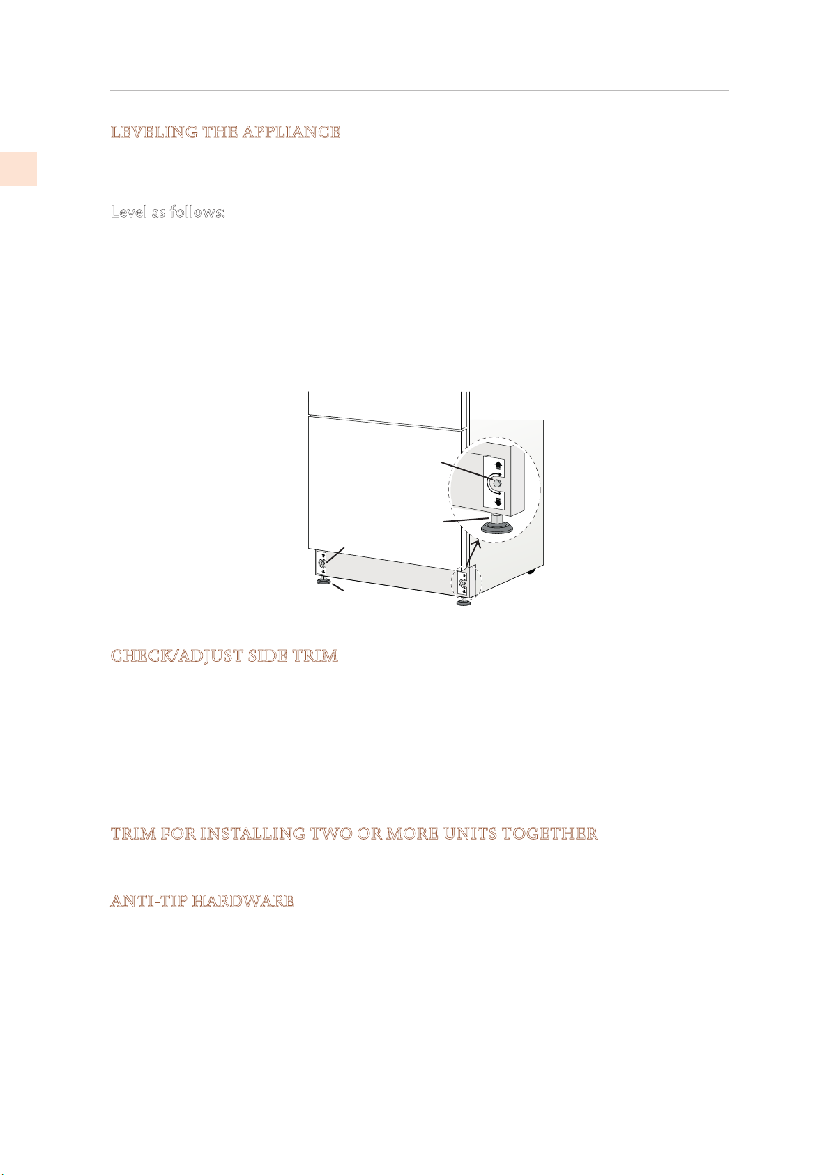
LEVELING THE APPLIANCE
(CONT.)
EN
Adjust the appliance level by means of the front leveling feet and the rear adjustable wheels.
Leveling must be done after the appliance has been moved into place.
Level as follows:
1) Remove the bottom grille if necessary (it is kept in position by magnets)
2) Adjust the front using the leveling feet (1) by means of a 17 mm (or 11/16") open-end or
adjustable wrench.
3) Adjust the height of the rear by turning the front adjusting bolts (2) clockwise or counterclockwise as required.
4) Reinstall the grill.
2
1
2
1
CHECK/ADJUST SIDE TRIM
The standard side trim fits an opening of the specified dimensions, as listed on page 5 and
following pages.
If the cutout is a bit wider or not perfectly square, the trim can be adjusted to fit.
The suggested method is to use spacers between the appliance and the trim strip under each of
the five screws securing each trim strip. Flat washers can be used as spacers, select thicknesses
as appropriate.
This adjustment should be done before any decorative panels are mounted to the doors.
TRIM FOR INSTALLING TWO OR MORE UNITS TOGETHER
When installing units side-by-side, a special trim kit must be used on the facing sides. See
"INSTALLING TWO OR MORE UNITS TOGETHER" on page 27.
ANTI-TIP HARDWARE
The anti-tip hardware installation is detailed on page31, and must be completed after the
appliance is in place and has been leveled.
However, you may wish to make the preparations before mounting any decorative panels.
30
©2019 Hestan Commercial Corporation
Page 33
FINAL INSTALLATION
2-3⁄8” [59]
1
2
3
4
(CONT.)
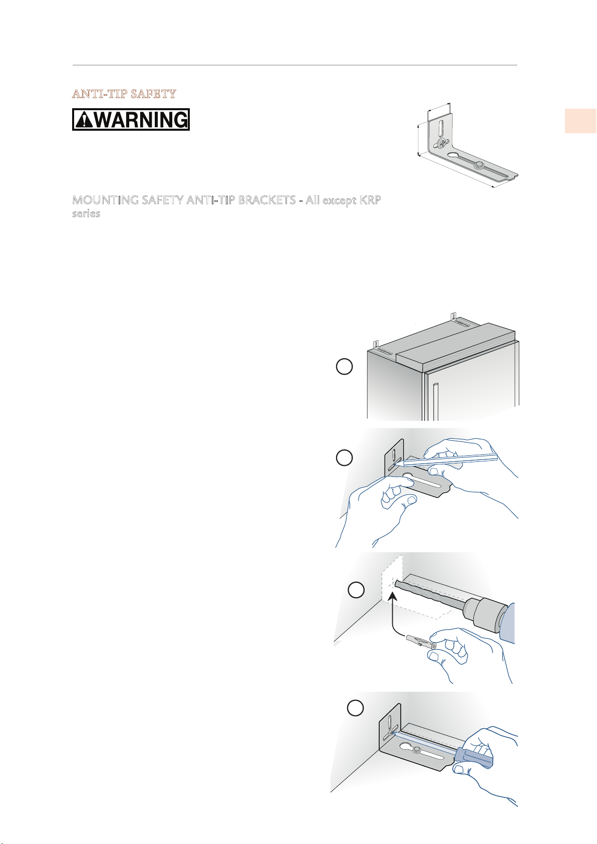
ANTI-TIP SAFETY
1-5⁄8” [45]
To avoid danger of the appliance tipping over it is mandatory to secure
the appliance to the wall by means of the two provided brackets.
6” [152]
MOUNTING SAFETY ANTI-TIP BRACKETS - All except KRP
series
When using the anti-tip brackets, they should be applied as illustrated using the provided
screws and wall anchors.
1) Find the mounting holes on top of the appliance, and determine how the bracket must
align with the wall.
2) Mark the wall where the holes are needed.
3) Drill the wall with an 5/16” [8 mm] bit and insert
the wall anchor.
EN
4) Position the bracket and secure it first to the
appliance, then to the wall.
In addition, it is suggested:
• The side trim pieces on both sides must be secured
to the unit with the provided screws
• The side trim pieces must be screwed to the
cabinets at all provided attachment points.
• The cabinet must be securely attached to the wall
to assure the stability of the appliance.
When two units are installed together, the anti-tip
brackets are required for each of them.
In addition, the correct joining kit must be installed and
the units must be secured to the adjoining cabinets by
means of the side trim pieces, as above.
2019 Hestan Commercial Corporation
31
Page 34
FINAL INSTALLATION
(CONT.)
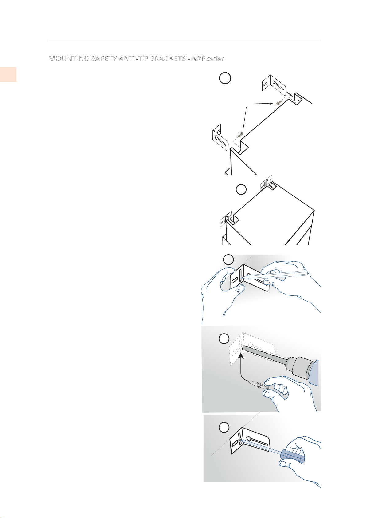
MOUNTING SAFETY ANTI-TIP BRACKETS - KRP series
EN
To avoid danger of the appliance tipping over it is
mandatory to secure the appliance to the wall by
means of the two provided brackets.
1) The appliance has one screw in place where each
bracket will attach. (See figure to right.) Remove
the screws and set aside.
2) Determine location of brackets and mark the
wall accordingly. Note that the brackets can be
installed facing in or out, as preferred.
3) Roll the unit away from the wall, and mark the hole
locations.
4) Drill anchor holes and install the anchors.
5) Mount the bracket to the wall, then roll the
appliance into position and attach the bracket
to the appliance using the screws saved from (1)
above.
In addition, it is suggested:
• The side trim pieces on both sides must be
secured to the unit with the provided screws
• The side trim pieces must be screwed to the
cabinets at all provided attachment points.
• The cabinet must be securely attached to the wall
to assure the stability of the appliance.
1
Anti-tip
mounting
screws
2
3
When two units are installed together, the anti-tip
brackets are required for each of them.
In addition, the correct joining kit must be installed
and the units must be secured to the adjoining
cabinets by means of the side trim pieces, as above..
4
5
32
©2019 Hestan Commercial Corporation
Page 35
FINAL INSTALLATION
(CONT.)
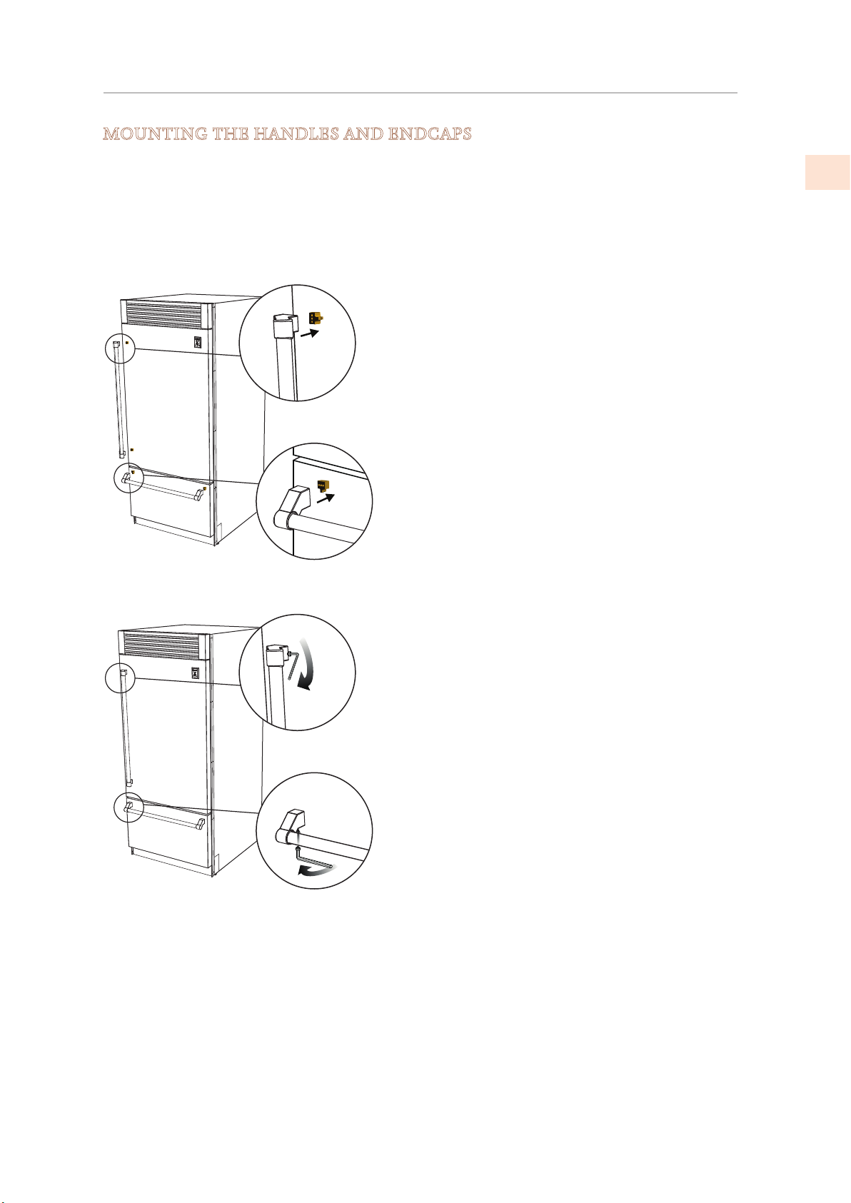
MOUNTING THE HANDLES AND ENDCAPS
Handles and endcaps are provided with all stainless and color models. Handles are located in
protective wrapping, taped to the back of the refrigerator. Remove the handles before moving
the refrigerator into its cut-out or opening. Endcaps are located in a cardboard box inside the
refrigerator.
It is recommended that two people work together to assemble and apply the handles and
endcaps. Follow the steps below to complete the mounting process.
Insert the handle into the endcaps and position the
endcaps over the supports that are pre-mounted on
the door and drawer.
• Use caution not to scratch the door surface.
• It is recommended that one person holds
the handle and endcaps in position while the
second person inserts the provided set screws
used to secure the handle.
EN
The provided set screws are located in the box
with the endcaps. Using a 2.5 mm hex wrench,
insert the set screw into the hole in the endcap
and carefully tighten. The endcap is then properly
secured to the door/drawer. Repeat this step for
the other endcaps.
2019 Hestan Commercial Corporation
33
Page 36
FINAL INSTALLATION
(CONT.)
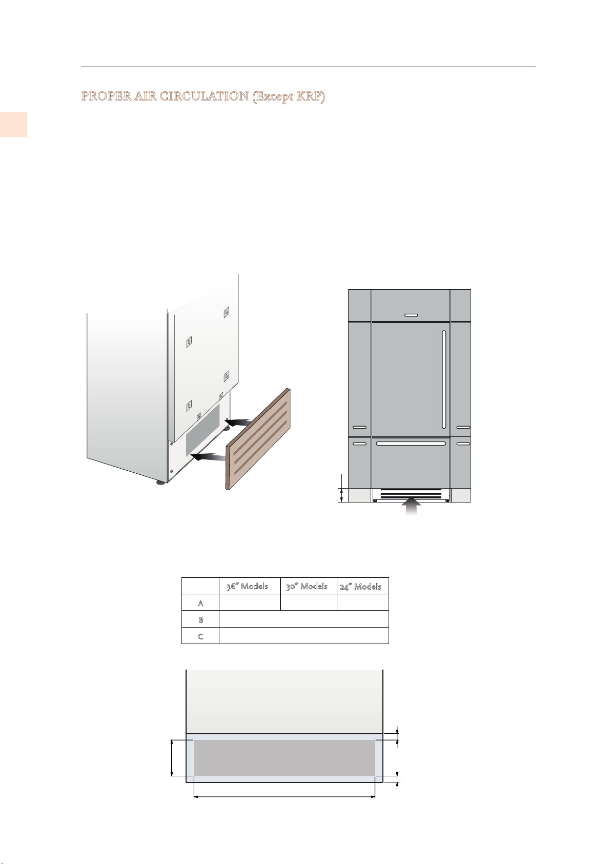
PROPER AIR CIRCULATION (Except KRP)
EN
A forced air system assures ventilation through a grill positioned in the
lower front of the unit. If the kitchen design includes an applied toekick, it
must have ample openings/slots to maintain proper air flow as illustrated
below. Holes/slots can be of any size and shape, provided that the total open
area amounts to 50% of the overall size of the decorative cover.
In this case, to guarantee proper air flow, it is recommended to remove the
front grille included with the unit. The provided grille is secured to the unit
with magnetic plates and can be easily removed. The cover should be
removed for regular cleaning and removal of dust. If a decorative
grill is used, remove the provided grill to allow for proper air flow.
100 (4”)
The chart and illustration below provides the proper amount of
air flow necessary to maintain. (All models except KRP.)
3366”” MMooddeellss
886600 ((3333- 77//88””))
A
B
C
B
3300”” MMooddeellss
774400 ((2299 11//88””))
>110000 ((44””))
1100 ((33//88””))
A
2244”” MMooddeellss
556600 ((2222””))
C
C
34
©2019 Hestan Commercial Corporation
Page 37
FINAL INSTALLATION
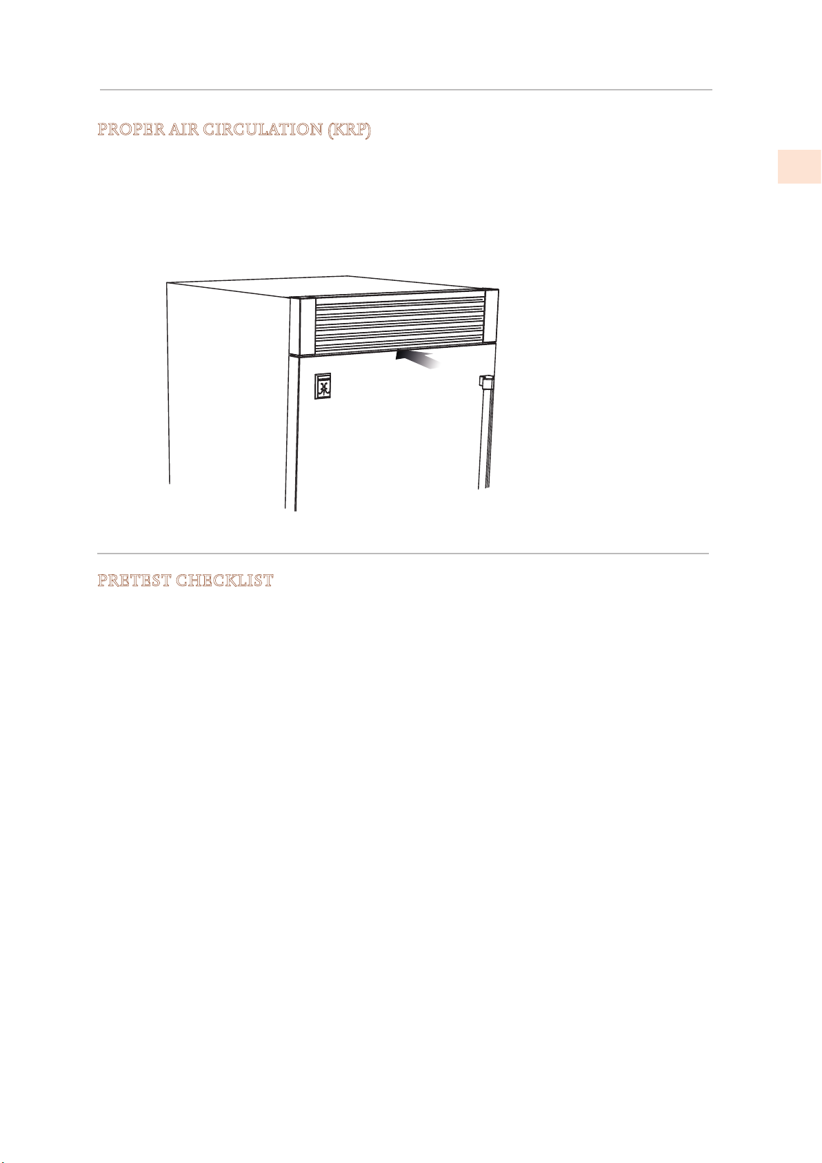
PROPER AIR CIRCULATION (KRP)
(CONT.)
For KRP models, ventilation is provided by a forced air system through a grill in the
top of the refrigerator. This open space in the grill must not be restricted by any
cover or device that would reduce the proper airflow, as it would reduce product
efficiency and increase energy consumption. A vent must be provided at the rear
for the air to exit. See page 5 for location and dimensions.
TESTING AND INITIAL START UP
EN
PRETEST CHECKLIST
; Check that the connection to the water system does not have any leaks and that the valve
is easily accessible.
; Check that the electrical connection is correctly installed and that the circuit breaker is
identified/marked for later use.
; Check that the unit is level and aligns with adjacent cabinets.
; Check that the anti-tip brackets are secure, and the side connectors are secure with trim in
place.
; Check that all adhesive tape and external or internal temporary protective packaging have
been removed.
; Check the perfect closing of the doors and the smooth sliding of the drawers and shelves.
; If the unit has an icemaker, make sure the water filter cartridge is installed. (Unless filtered
water is being provided to the unit.)
2019 Hestan Commercial Corporation
35
Page 38
TESTING AND INITIAL START-UP
Turn icemaker ON
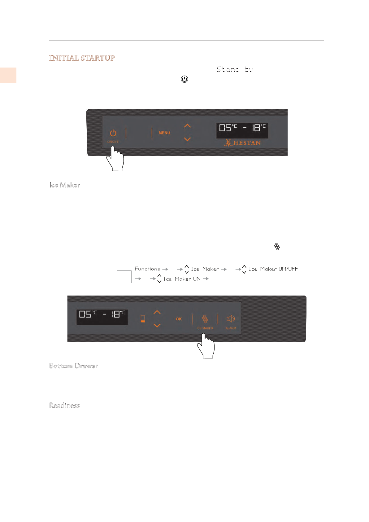
INITIAL STARTUP
(CONT.)
EN
Once the appliance is plugged in, the display should show .
Turn the appliance ON by pressing the Power button for three seconds. The display will
show the message “Initial test” for approximately 2 minutes. After this phase the compressors
will start up and remain on until the default temperature (set at the factory) is reached. Allow
ample time for the refrigerator to reach this temperature before loading any items (6-12 hrs).
Ice Maker
If the appliance is provided with an ice maker:
1) Make sure that the water filter cartridge is properly installed
2) Purge air from the water lines by enacting the ‘Manual Clean’ function from the Menu>Functions->Water Filter options. You may need to complete this sequence several times
until you stop hearing air sputtering from the ice maker fill tube.
3) Once the procedure has completed, turn the Ice Maker on by touching the button (KRP,
KRB) or by using the menu:
OK
OK
OKOK
Bottom Drawer
Models KRP, KRB, and KRW have a bottom drawer which defaults to freezer operation. The
drawer can also be set to other modes of operation. See the Use and Care manual for more
information.
Readiness
If at first the Start Up message does not appear but other information in the display does
appear (such as Fridge too warm, Freezer too warm, or audible signals are heard), the
refrigerator has still begun the normal cooling process.
If this is the case, deactivate any audible signals by pressing the Alarm button, close the door
and wait until the set temperature is reached.
36
It is necessary to let the unit reach the correct temperature prior to placing food or beverages
in it. (Allow 6-12 hours.)
For further information about the appliance operation, refer to the Use and Care Manual.
©2019 Hestan Commercial Corporation
Page 39

PARTS AND SERVICE
PARTS LIST
Please visit the Hestan website to access the parts list for your Hestan Indoor product:
www.hestanhome.com.
SERVICE
All warranty and non-warranty repairs should be performed by qualified service personnel.
To locate an authorized service agent in your area, contact your Hestan dealer, local
representative, or Hestan Customer Service. Before you call, please have the model number
and serial number information ready.
Hestan Commercial Corporation
3375 E. La Palma Avenue
Anaheim, CA 92806
(888) 905-7463
EN
LIMITED WARRANTY
WHAT THIS LIMITED WARRANTY COVERS:
Hestan Commercial Corporation (“HCC”) warrants to the original consumer purchaser of
a Hestan Indoor Cooling product (the “Product”) from an HCC authorized dealer that the
Product is free from defective materials or workmanship for a period of two (2) years from the
date of original retail purchase or closing date for new construction, whichever period is longer
(“Limited Warranty Period”). HCC agrees to repair or replace, at HCC’s sole option, any part
or component of the Product that fails due to defective materials or workmanship during the
Limited Warranty Period. This Limited Warranty is not transferable and does not extend to
anyone beyond the original consumer purchaser (“Purchaser”). This Limited Warranty is valid
only on Products purchased and received from an HCC authorized dealer in the fifty United
States, the District of Columbia and Canada. This Limited Warranty applies only to Products
in non-commercial use and does not extend to Products used in commercial applications.
HOW TO OBTAIN WARRANTY SERVICE:
If the Product fails during the Limited Warranty Period for reasons covered by this Limited
Warranty, the Purchaser must immediately contact the dealer from whom the Product was
purchased or HCC at 888.905.7463.
Purchaser is responsible for making the Product reasonably accessible for service or for paying
the cost to make the Product reasonably accessible for service. Service is to be provided
during normal business hours of the authorized Hestan Commercial Service Provider. To the
extent Purchaser requests service outside of the normal business hours of the authorized
Hestan Commercial Service Provider, Purchaser will pay the difference between regular rates
and overtime or premium rates. Purchaser is required to pay all travel costs for travel beyond
50 miles (one way) from the nearest authorized Hestan Commercial Service Provider.
© 2019 Hestan Commercial Corporation
37
Page 40

LIMITED WARRANTY
(CONT.)
EXTENSIONS TO TWO YEAR LIMITED WARRANTY PERIOD:
EN
In addition to the Two-Year Limited Warranty, the following components have extended
warranty coverage as specifically set forth below:
The Product’s compressor, condenser, evaporator, drier and all connecting tubing (where
applicable are warranted to be free from defects in material and workmanship under normal
non-commercial use and service for a period of five (5) years of the original Purchaser. This
excludes surface corrosion, scratches, and discoloration which may occur during normal use
and is limited to replacement of the defective part(s), including labor, shipping and handling, as
applicable.
The Product’s compressor, condenser, evaporator, drier and all connecting tubing (where
applicable) are warranted to be free from defects in material and workmanship under normal
non-commercial use and service for a period of twelve (12) years of the original Purchaser. This
excludes surface corrosion, scratches, and discoloration which may occur during normal use
and is limited to replacement of the defective part(s), with the Purchaser paying all other costs,
including labor, shipping and handling, as applicable.
WHAT THIS LIMITED WARRANTY DOES NOT COVER:
This Limited Warranty does not cover and HCC will not be responsible for and will not pay
for: damage to or defects in any Product not purchased from an HCC authorized dealer; color
variations in color finishes or other cosmetic damage; failure or damage from abuse, misuse,
accident, re, natural disaster, commercial use of the Product, or loss of electrical power or gas
supply to the Product; damage from alteration, improper installation, or improper operation
of the Product; damage from improper or unauthorized repair or replacement of any part or
component of the Product; damage from service by someone other than an authorized agent or
representative of the Hestan Commercial Service Network; normal wear and tear; damage from
exposure of the Product to a corrosive atmosphere containing chlorine, fluorine, or any other
damaging chemicals; damage resulting from the failure to provide normal care and maintenance
to the Product; damage HCC was not notified of within the Limited Warranty Period; and
incidental and consequential damages caused by any defective material or workmanship.
ARBITRATION:
This Limited Warranty is governed by the Federal Arbitration Act. Any dispute between
Purchaser and HCC regarding or related to the Product or to this Limited Warranty shall be
resolved by binding arbitration only on an individual basis with Purchaser. Arbitration will be
conducted by the American Arbitration Association (“AAA”) in accordance with its Consumer
Arbitration Rules or by JAMS. The arbitration hearing shall be before one arbitrator appointed
by the AAA or JAMS. The arbitrator shall not conduct class arbitration and Purchaser shall not
bring any claims against HCC in a representative capacity on behalf of others.
LIMITATION OF LIABILITY:
This Limited Warranty is the final, complete and exclusive agreement between HCC and
Purchaser regarding the Product.
THERE ARE NO EXPRESS WARRANTIES OTHER THAN THOSE LISTED AND DESCRIBED
ABOVE. NO WARRANTIES WHETHER EXPRESS OR IMPLIED, INCLUDING, BUT NOT
LIMITED TO, ANY IMPLIED WARRANTIES OF MERCHANTABILITY OR FITNESS FOR A
PARTICULAR PURPOSE SHALL APPLY AFTER THE LIMITED WARRANTY PERIOD STATED
ABOVE. NO OTHER EXPRESS WARRANTY OR GUARANTY GIVEN BY ANY PERSON,
FIRM OR CORPORATION WITH RESPECT TO THIS PRODUCT SHALL BE BINDING ON
HCC. HCC ASSUMES NO RESPONSIBILITY THAT THE PRODUCT WILL BE FIT FOR
ANY PARTICULAR PURPOSE, EXCEPT AS OTHERWISE PROVIDED BY APPLICABLE
38
© 2019 Hestan Commercial Corporation
Page 41

LIMITED WARRANTY
LAW. HCC SHALL NOT BE LIABLE FOR LOSS OF REVENUE OR PROFITS, FAILURE TO
REALIZE SAVINGS OR OTHER BENEFITS, OR ANY OTHER SPECIAL, INCIDENTAL OR
CONSEQUENTIAL DAMAGES CAUSED BY THE USE, MISUSE OR INABILITY TO USE THE
PRODUCT, REGARDLESS OF THE LEGAL THEORY ON WHICH THE CLAIM IS BASED,
AND EVEN IF HCC HAS BEEN ADVISED OF THE POSSIBILITY OF SUCH DAMAGES. NO
RECOVERY OF ANY KIND AGAINST HCC SHALL BE GREATER IN AMOUNT THAN THE
PURCHASE PRICE OF THE PRODUCT. WITHOUT LIMITING THE FOREGOING, YOU
ASSUME ALL RISK AND LIABILITY FOR LOSS, DAMAGE OR INJURY TO YOU AND YOUR
PROPERTY AND TO OTHERS AND THEIR PROPERTY ARISING OUT OF THE USE, MISUSE
OR INABILITY TO USE THE PRODUCT NOT CAUSED DIRECTLY BY THE NEGLIGENCE OF
HCC. THIS LIMITED WARRANTY STATES YOUR EXCLUSIVE REMEDY.
No oral or written representation or commitment given by anyone, including but not limited
to, an employee representative or agent of HCC will create a warranty or in any way increase
the scope of this express Limited Two Year Warranty. If there is any inconsistency between
this Limited Warranty and any other agreement or statement included with or relating to the
Product, this Limited Warranty shall govern. If any provision of this Limited Warranty is found
invalid or unenforceable, it shall be deemed modified to the minimum extent necessary to make
it enforceable and the remainder of the Limited Warranty shall remain valid and enforceable
according to its terms.
(CONT.)
EN
INTERACTION OF LAWS WITH THIS LIMITED WARRANTY:
Some states, provinces or territories may not allow limitations on how long an implied
warranty lasts or the exclusion or limitation of incidental or consequential damages, so the
above limitations or exclusions may not apply to you. Some states, provinces or territories may
provide for additional warranty rights and remedies, and the provisions contained in this Limited
Warranty are not intended to limit, modify, take away from, disclaim or exclude any mandatory
warranty requirements provided by states, provinces or territories, including certain implied
warranties. This warranty gives you specific legal rights, and you may also have other rights
which vary depending on location.
Any questions about this Limited Warranty may be directed to
Hestan Commercial Corporation at (888) 905-7463
© 2019 Hestan Commercial Corporation
39
Page 42

EN
40
© 2019 Hestan Commercial Corporation
Page 43
LE NON-RESPECT À LA LETTRE DE CES INSTRUCTIONS PEUT
CAUSER UN INCENDIE OU UNE EXPLOSION, QUI POURRAIT
ENTRAÎNER DES DOMMAGES MATÉRIELS, DES BLESSURES OU
LA MORT.
Ne pas entreposer ou utiliser d’essence ou tout autre liquide ou gaz inflammable à
proximité de cet appareil ou de tout autre appareil.
L’installation et le service doivent être effectués par un installateur qualifié ou une
agence de service.
NE PAS RÉPARER, REMPLACER OU ENLEVER TOUTE PIÈCE DE L’APPAREIL,
SAUF SI SPÉCIFIQUEMENT RECOMMANDÉ DANS LES MANUELS. UNE
INSTALLATION, UN ENTRETIEN OU UNE MAINTENANCE INCORRECTS
PEUT ENTRAÎNER DES BLESSURES OU DES DOMMAGES MATÉRIELS.
CONSULTEZ CE MANUEL DE L’ORIENTATION. TOUS LES AUTRES SERVICES
DEVRAIENT ÊTRE EFFECTUÉS PAR UN TECHNICIEN DE SERVICE HESTAN
AUTORISÉ.
LISEZ ATTENTIVEMENT ET COMPLÈTEMENT CES INSTRUCTIONS
AVANT D’INSTALLER OU D’UTILISER VOTRE APPAREIL AFIN DE
RÉDUIRE LES RISQUES D’INCENDIE, DE BRÛLURE OU D’AUTRES
BLESSURES. CONSERVER CE MANUEL POUR RÉFÉRENCE FUTURE.
DÉFINITIONS DE SÉCURITÉ
CECI INDIQUE QUE L’INOBSERVATION DE CET AVERTISSEMENT
PEUT ENTRAÎNER DES BLESSURES GRAVES VOIRE MORTELLES.
CECI INDIQUE QUE L’INOBSERVATION DE CET AVERTISSEMENT
PEUT ENTRAÎNER DES BLESSURES MINEURES OU MODÉRÉES.
CECI INDIQUE QUE L’INOBSERVATION DE CET AVERTISSEMENT
PEUT ENTRAÎNER DES DOMMAGES DE L’APPAREIL OU DES
DÉGÂTS MATÉRIELS.
INSTALLATEUR: LAISSER CE MANUEL AVEC LE PROPRIÉTAIRE DE
L’APPAREIL.
PROPRIÉTAIRE: CONSERVEZ CE MANUEL POUR RÉFÉRENCE
FUTURE.
Page 44

FR
TABLES DES MATIERES
1 PRÉCAUTIONS DE SÉCURITÉ - AVANT DE COMMENCER
2 NUMÉROS DE MODÈLE
3 PLAQUE SIGNALÉTIQUE
3 EXIGENCES RÉGLEMENTAIRES / CODE
4 POUR LA SÉCURITÉ DES ENFANTS
4 LIEU ET PRÉPARATION
12 CONNECTER
15 PRÉPARATION DES PANNEAUX DÉCORATIFS
27 INSTALLATION FINALE
35 ESSAIS ET DÉMARRAGE INITIAL
37 LISTE DES PIÈCES
37 SERVICE
37 GARANTIE LIMITÉE
PRÉCAUTIONS DE SÉCURITÉ - AVANT DE COMMENCER
S’il est bien entretenu, cet appariel Hestan procurera un service sûr et fiable pendant de
nombreuses années. Lorsqu’on se sert de cet appareil, les pratiques élémentaires suivantes en
matière de sécurité doivent être adoptées.
IMPORTANT: Conservez ces instructions pour l’utilisation locale des services publics.
INSTALLATEUR: Veuillez laisser ces instructions d’installation avec le propriétaire.
PROPRIÉTAIRE: Veuillez conserver ces instructions d’installation pour référence
future.
Cette four est conçue pour un usage domestique uniquement. Elle ne l’est PAS pour être
installée dans des maisons préfabriquées (mobiles) ou dans des véhicules récréatifs. N’installez
PAS cette four à l’extérieur.
RISQUE DE CHOC ÉLECTRIQUE
Débranchez l’alimentation avant d’installer ou d’entretenir l’appareil.
Avant de le mettre sous tension, assurez-vous que toutes les commandes
sont en position «OFF». Ne pas le faire peut entraîner la mort ou un choc
électrique.
MISE À LA TERRE ÉLECTRIQUE
Cet appareil doit être mis à la terre. La mise à la terre réduit le
risque de choc électrique en cas de court-circuit. Lisez la section
BRANCHEMENTS ÉLECTRIQUES de ce manuel pour des instructions
complètes.
© 2019 Hestan Commercial Corporation
1
Page 45
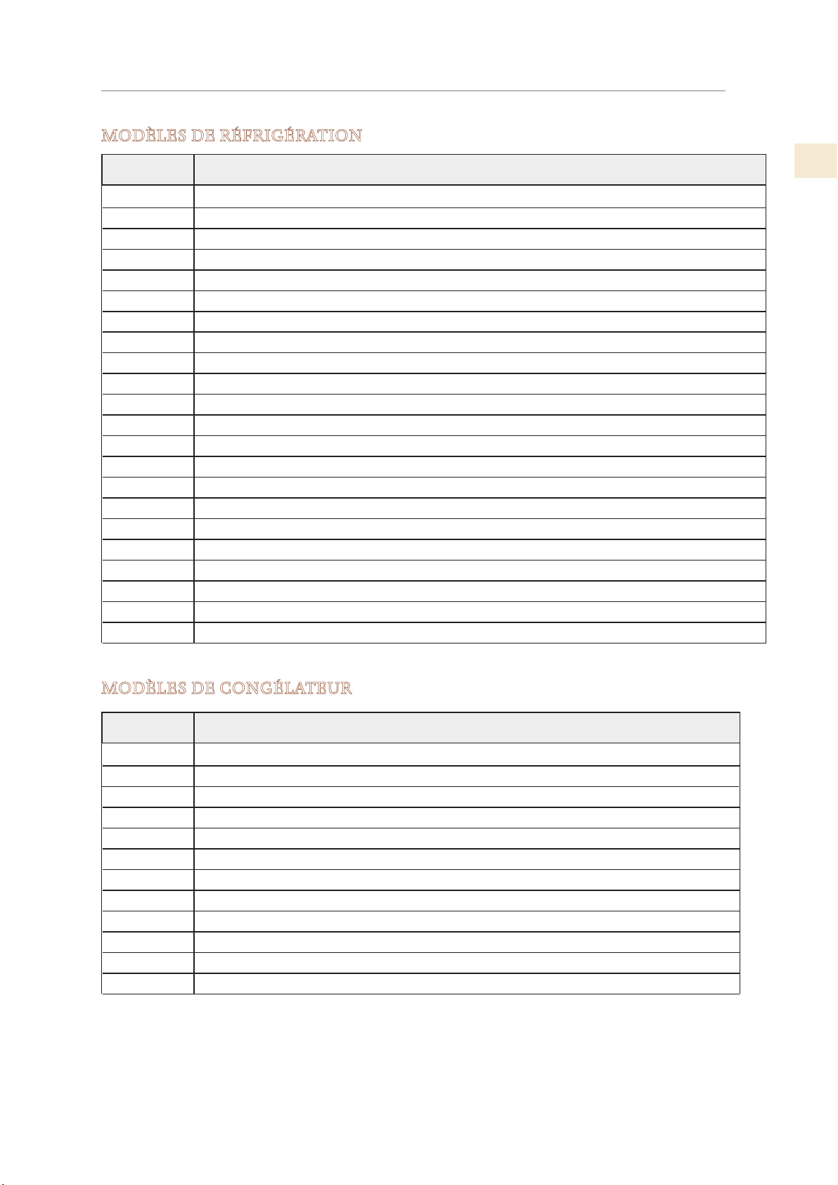
NUMÉROS DE MODÈLE
KFCL30-XX
Colonne de congélateur, couleur, charnière à gauche, 30 po
MODÈLES DE RÉFRIGÉRATION
Modèles
KRPR36 Réfrigérateur à congélateur inférieur, compresseur supérieur, Pro, charnière à droite, 36 po
KRPL36
KRPR36-XX Réfrigérateur à congélateur inférieur, compresseur supérieur, Pro, couleur, charnière à droite, 36 po
KRPL36-XX Réfrigérateur à congélateur inférieur, compresseur supérieur, Pro, couleur, charnière à gauche, 36 po
KRBR36 Réfrigérateur à congélateur inférieur, compresseur inférieur, charnière à droite, 36 po
KRBL36
KRBR36-OV Réfrigérateur à congélateur inférieur, compresseur inférieur, recouvrement, charnière à droite, 36 po
KRBL36-OV Réfrigérateur à congélateur inférieur, compresseur inférieur, recouvrement, charnière à gauche, 36 po
KRBR36-XX Réfrigérateur à congélateur inférieur, compresseur inférieur, couleur, charnière à droite, 36 po
KRBL36-XX Réfrigérateur à congélateur inférieur, compresseur inférieur, couleur, charnière à gauche, 36 po
KRCR24 Colonne de réfrigérateur, charnière à droite, 24 po
KRCL24 Colonne de réfrigérateur, charnière à gauche, 24 po
KRCR24-OV Colonne de réfrigérateur, recouvrement, charnière à droite, 24 po
KRCL24-OV Colonne de réfrigérateur, recouvrement, charnière à gauche, 24 po
KRCR24-XX Colonne de réfrigérateur, couleur, charnière à droite, 24 po
KRCL24-XX Colonne de réfrigérateur, couleur, charnière à gauche, 24 po
KRCR30 Colonne de réfrigérateur, charnière à droite, 30 po
KRCL30 Colonne de réfrigérateur, charnière à gauche, 30 po
KRCR30-OV Colonne de réfrigérateur, recouvrement, charnière à droite, 30 po
KRCL30-OV Colonne de réfrigérateur, recouvrement, charnière à gauche, 30 po
KRCR30-XX Colonne de réfrigérateur, couleur, charnière à droite, 30 po
KRCL30-XX Colonne de réfrigérateur, couleur, charnière à gauche, 30 po
Réfrigérateur à congélateur inférieur , compresseur supérieur, Pro, charnière à gauche, 36 po
Réfrigérateur à congélateur inférieur, compresseur inférieur, charnière à droite, 36 po
Description
FR
MODÈLES DE CONGÉLATEUR
Modèles
KFCR24 Colonne de congélateur, charnière à droite, 24 po
KFCL24 Colonne de congélateur, charnière à gauche, 24 po
KFCR24-OV Colonne de congélateur, recouvrement, charnière à droite, 24 po
KFCL24-OV Colonne de congélateur, recouvrement, charnière à gauche, 24 po
KFCR24-XX Colonne de congélateur, couleur, charnière à droite, 24 po
KFCL24-XX Colonne de congélateur, couleur, charnière à gauche, 24 po
KFCR30 Colonne de congélateur, charnière à droite, 30 po
KFCL30 Colonne de congélateur, charnière à gauche, 30 po
KFCR30-OV Colonne de congélateur, recouvrement, charnière à droite, 30 po
KFCL30-OV Colonne de congélateur, recouvrement, charnière à gauche, 30 po
KFCR30-XX Colonne de congélateur, couleur, charnière à droite, 30 po
Description
© 2019 Hestan Commercial Corporation
2
Page 46
NUMÉROS DE MODÈLE
(SUITE)
FR
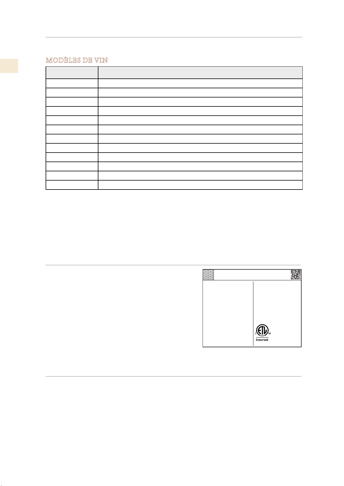
MODÈLES DE VIN
Modèles Description
KWCR24
KWCL24
KWCR24-OV
KWCL24-OV
KWCR24-XX
KWCL24-XX
KRWR24
KRWL24
KRWR24-OV
KRWL24-OV
KRWR24-XX
KRWL24-XX
REMARQUE: -XX indique le modèle de couleur.
-BK pour Stealth - Noir -WH pour Froth - Blanc -RD pour Matador - Rouge
-YW pour Sol - Jaune -OR pour Citra - Orange -BG pour Tin Roof - Bourgogne
-PP pour Lush - Violet -BU pour Prince - Bleu -GR pour Grove - Vert
-GG pour Pacific Fog - Gris graphite -TQ pour Bora Bora - Turquoise
Colonne de vin, charnière à droite, 24 po
Colonne de vin, charnière à gauche, 24 po
Colonne de vin, recouvrement, charnière à droite, 24 po
Colonne de vin, recouvrement, charnière à gauche, 24 po
Colonne de vin, couleur, charnière à droite, 24 po
Colonne de vin, couleur, charnière à gauche, 24 po
Réfrigérateur avec vin, charnière à droite, 24 po
Réfrigérateur avec vin, charnière à gauche, 24 po
Réfrigérateur avec vin, recouvrement, charnière à droite, 24 po
Réfrigérateur avec vin, recouvrement, charnière à gauche, 24 po
Réfrigérateur avec vin, couleur, charnière à droite, 24 po
Réfrigérateur avec vin, couleur, charnière à gauche, 24 po
PLAQUE SIGNALÉTIQUE
L’étiquette d’évaluation contient des informations
importantes sur votre appareil Hestan, telles que le
modèle, le numéro de série et les caractéristiques
électriques.
L’étiquette d’évaluation est située sur la paroi interne de
l’appareil.
Si un entretien est nécessaire, contactez le service
clientèle de Hestan avec les informations sur le modèle
et le numéro de série figurant sur la plaque.
HESTAN COMMERCIAL CORP.
ANAHEIM, CA - USA
ozFridge Gas Fill Charge
7
Quantité de Gaz Réfrigerateur
Freezer Gas Fill Charge
Quantité de Gaz Congélateur
Total Absorbed Current
Courant Absorbée Totale
Voltage
Tension
Frequency
Frequence
Refrigerant Gas Type
Type de Gaz Rèfrigerant
Made in Italy
MODEL
KRP36
0
CODE
1
A
FI24RC-RO
SER.NO./N° SERIE
115
V
XXXXXXXXXXX
60
Hz
R134a
3186660
ETL LISTED
CONFORMS TO
ANSI/UL STD 250
CERTIFIED TO CAN/CSA
STD C22.2 NO.63
PLAQUE SIGNALÉTIQUE TYPIQUE
EXIGENCES RÉGLEMENTAIRES / CODE
L’installation de cet appareil doit être effectuée conformément aux codes locaux. En l’absence
de codes locaux, cet appareil doit être installé conformément au code national de l’électricité et
aux codes locaux.
Cet appareil doit être mis à la terre conformément aux codes locaux ou en l’absence de codes
locaux avec le code électrique national ANSI / NFPA 70 ou le code électrique canadien CSA
C22.1.
© 2019 Hestan Commercial Corporation
3
Page 47
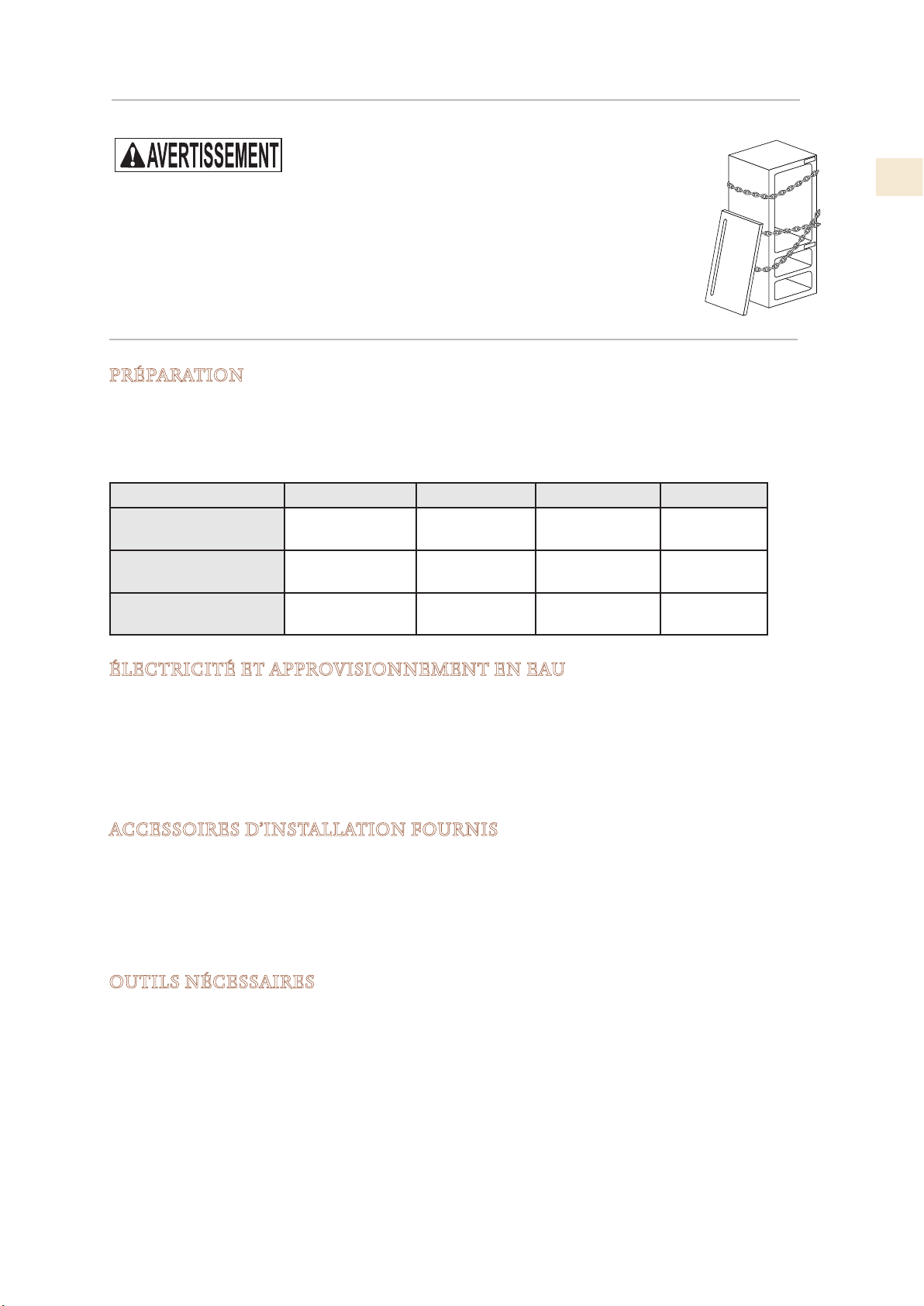
POUR LA SÉCURITÉ DES ENFANTS
Risque d’enfermement pour les enfants. Avant de jeter un vieux réfrigérateur ou
congélateur :
• Retirer les portes
• Laisser les étagères en place afin d’empêcher que des enfants grimpent dedans.
LIEU ET PRÉPARATION
PRÉPARATION
Avant de déplacer le lave-vaisselle, protégez tout revêtement de sol fini et fermez la porte pour
éviter les dommages. NE PAS soulever le lave-vaisselle par la poignée de la porte. Assurez-vous
que l’alimentation peut être fournie à l’emplacement sélectionné.
DIMENSIONS ET POIDS EMBALLÉS
Largeur Hauteur Profondeur Poids
Modèles de 24 po
Modèles de 30 po
M0dèles de 36 po
25-5/8 po
[650mm]
31-1/2 po
[800mm]
37-3/8 po
[950mm]
89 po
[2260mm]
89 po
[2260mm]
89 po
[2260mm]
31-1/2 po
[800mm]
31-1/2 po
[800mm]
31-1/2 po
[800mm]
507 lb
[230kg]
606 lb
[275kg]
650 lb
[295kg]
FR
ÉLECTRICITÉ ET APPROVISIONNEMENT EN EAU
Tension d’alimentation
Unités avec machine à glaçons: Ne vous connectez qu’à de l’eau potable.
Pression d’alimentation: en cas de filtration externe, entre 7,3 à 73 psi [0,5 à 5,0 Bar]
Si vous utilisez un filtre à eau fourni, de 25,4 à 73 psi [1,75 à 5,0 bar].
Tube de raccordement d’eau: femelle 3/4 po (voir page 13 pour plus de détails)
ACCESSOIRES D’INSTALLATION FOURNIS
Kit de montage sur panneaux personnalisé (inclus avec les modèles -OV uniquement)
Kit anti-renversement
Kit de connexion latérale
Voir "PRÉPARATION DE L’INSTALLATION" à la page 10 pour plus d'informations sur le
déballage.
OUTILS NÉCESSAIRES
Les outils suivants sont nécessaires pour l’installation du l’appliance:
• Tournevis cruciforme
• Percer et foret 1/8 ”, plus 3/8” pour maçonnerie
• clé plate ou réglable de 17 mm (ou 11/16 ”)
• Prise, rallonge et poignée de 13 mm (ou 1/2 ”)
• Clés Allen de 2,5 mm et 4 mm
Si vous installez deux unités ensemble
• Pince à riveter manuelle (pistolet à riveter)
© 2019 Hestan Commercial Corporation
4
Page 48
LIEU ET PRÉPARATION
min 84 po [2134]
83-1/2 po [2120] + 1 po [25]
9 po [230]
(SUITE)
DÉCOUPE D’INSTALLATION - MODÈLES KRP
FR
Hauteur de
l’encastrement
Encombrement avec
porte ouverte
84 po [2134] Largeur de
l’encastrement
57-7/8 po [1470] Angle d’ouverture de
la porte
35-1/2 po [900]
105°
Largeur 35-3/8 po [899] Hauteur 83-1/2 po [2120] + 1 po [25]
Profondeur (sans
25 po [635]
panneau)
Espace à réserver aux équerres anti-renversement
5-1/2 po [140]
4 po [100]
35-1/2 po [900]
5-1/2 po [140]
4 po [100]
40 po [101 6]
57-7/8 po [14 7 0]
min 3/8 po [10] 2-1/4 po [58]
22 po [560]
25 po [635]
25 po [635]
7-5⁄8 po [195]
5⁄16 po [8]
24-1/8 po [613] + 1 po [25]
5⁄16 po [8]
35-3/8 po [899]
3 po [75]
min 2 po [50]
min 3/8 po [10]
© 2019 Hestan Commercial Corporation
5
22 po [560]
27- 1/4 po [693]
de niveau
3-7/8 po [97] 20-3/8 po [516] 50 po [1296]
Page 49
LIEU ET PRÉPARATION
(SUITE)
DÉCOUPE D’INSTALLATION - MODÈLES KRB - OV
Hauteur de
l’encastrement
Encombrement avec
porte ouverte
84 po [2134] Largeur de
l’encastrement
57-7/8 po [1470] Angle d’ouverture
de la porte
35-1/2 po [900]
105°
Largeur 35-3/8 po [899] Hauteur 83-1/2 po [2120] + 1 po [25]
Profondeur (sans
24 po [610]
panneau)
Espace à réserver aux équerres anti-renversement
5-1/2 po [140 mm]
4 po [100 mm]
35-1/2 po [900 mm]
5-1/2 po [140 mm]
6-3/8 po [160 mm]
4 po [100 mm]
39 po [992 mm]
36 po: 57-7/8 po [1470 mm]
FR
min 84 po [2134 mm]
3/8 po [10 mm]
22 po [560 mm]
24 po [610 mm]
24 po [610 mm]
22 po [560 mm]
3/4 po [20 mm]
83-1/2 po + 1 po [2120 + 25 mm]
3⁄8 po + 1 po [721 + 25 mm]
28-
18-5⁄8 po [474 mm] 50-7⁄8 po [1293 mm]
35-3/8 po [899 mm]
9-3/4 po + 1 po
20-3/4 po [248+ 25 mm]
9-1⁄8 po + 1 po
[231 + 25 mm]
19-3/4 po [500 mm]
© 2019 Hestan Commercial Corporation
6
Page 50
LIEU ET PRÉPARATION
25 po [635]
+ 1 po [25]
5-1/2 po [140 mm]
5-1/2 po [140 mm]
4 po [100 mm]
4 po [100 mm]
min 84 po [2134 mm]
57-
7⁄8
po [1470 ]
(SUITE)
DÉCOUPE D’INSTALLATION- KRB MODÈLES AVEC SS OU COULEUR
FR
Hauteur de
l’encastrement
Encombrement avec
porte ouverte
84 po [2134] Largeur de
l’encastrement
57-7/8 po [1470] Angle d’ouverture
de la porte
35-1/2 po [900]
105°
Largeur 35-3/8 po [899] Hauteur 83-1/2 po [2120] + 1 po [25]
Profondeur 25 po [635]
Espace à réserver aux équerres anti-renversement
9 po [230]
40 po [1016 ]
35-1/2 po [900 mm]
105°
83- ½ po [2120 ] + 1 po [25]
po [10]
3⁄8
22 po [560]
25 po [635]
po [58]
¼
35-
3⁄8
po [899]
3 po [75]
22 po [560]
54-¼ po [1378]23- ⁄ po [587]
⁄po [9]
2-
7
28- ⁄po [732] + 1 po [25]
© 2019 Hestan Commercial Corporation
27-¼po [693]
5-¾ po [146]
Page 51
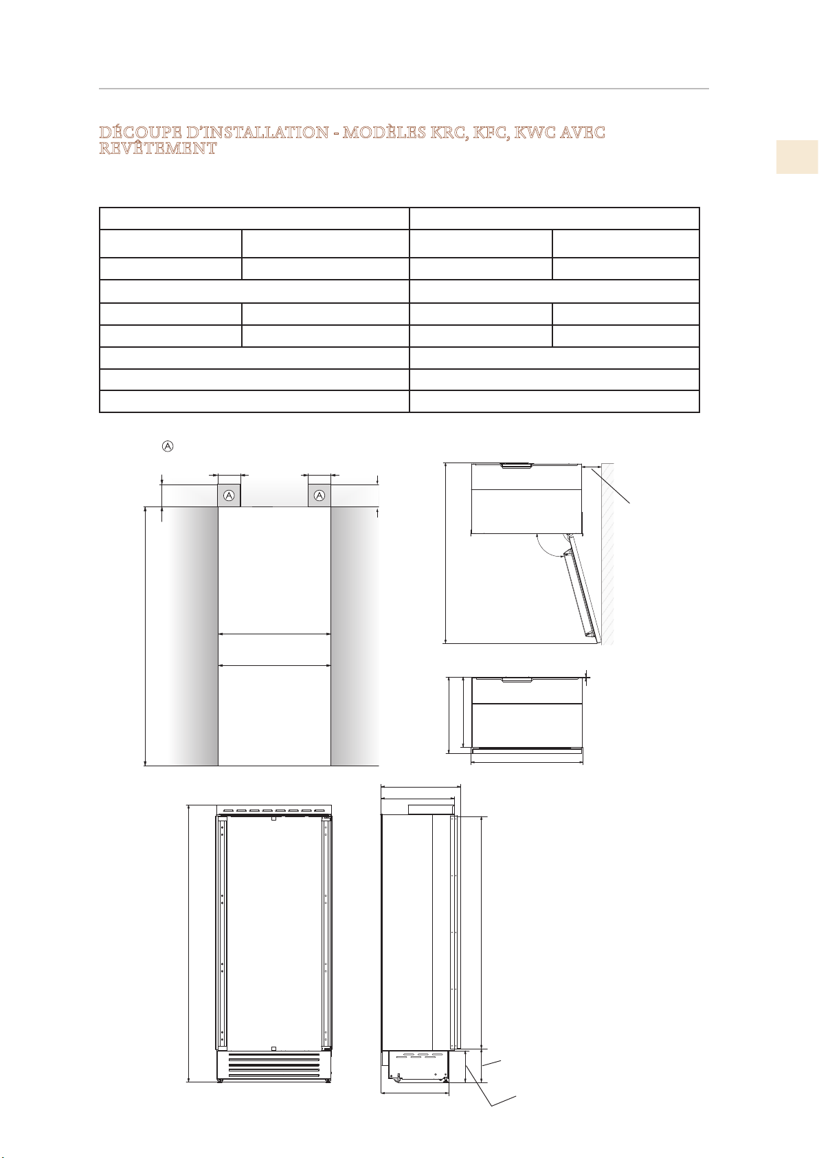
min 84 po [2134]
24 po: 1-1⁄16 po [27]
Zone à laisser libre pour les supports anti-basculement
LIEU ET PRÉPARATION
(SUITE)
DÉCOUPE D’INSTALLATION - MODÈLES KRC, KFC, KWC AVEC
REVÊTEMENT
RÉFRIGÉRATEURS ET CONGÉLATEURS À COLONNE DE 24 PO ET 30 PO
COLONNE À VIN DE 24 PO ET RÉFRIGÉRATEUR DE 24 PO AVEC VIN
Hauteur de l’encastrement Largeur de l’encastrement
Modèles de 24 po 84 po [2134 mm] Modèles de 24 po 23-3/4 po [600 mm]
Modèles de 30 po 84 po [2134 mm] Modèles de 30 po 29-5/8 po [750 mm]
Encombrement avec porte ouverte Largeur
Modèles de 24 po 46-1/4 po [1175 mm] Modèles de 24 po 23-5/8 po [599 mm]
Modèles de 30 po 52-1/8 po [1325 mm] Modèles de 30 po 29-1/2 po [749 mm]
Angle d’ouverture de la porte 105°
Hauteur 83-1/2 po [2120 mm] + 1 po [25 mm]
Profondeur (sans panneau) 24-1/4 po [615 mm]
FR
5-½ po [140]
4 po [100]
30 po: 29-5/8 po [750]
24 po: 23-3/4 po [600]
5-½ po [140]
4 po [100]
30 po: 52-1/8 po [1325]
24 po: 46-1/4 po [1175]
22-1/4 po [560]
24 po 1/4 [615]
24-1/4 po [615]
22-1/4 po [560]
105°
30 po: 2-1⁄8 po [53]
3⁄8 po [10]
30 po: 29-1/2 po [749]
24 po: 23-5/8 po [599]
83-½ po [2120] + 1 po [25]
19-¾ po [505]
¼ po [1808]
71-
¼ po [233] + 1 po [25]
9-
9-1⁄8 po [231] + 1 po [25]
© 2019 Hestan Commercial Corporation
8
Page 52
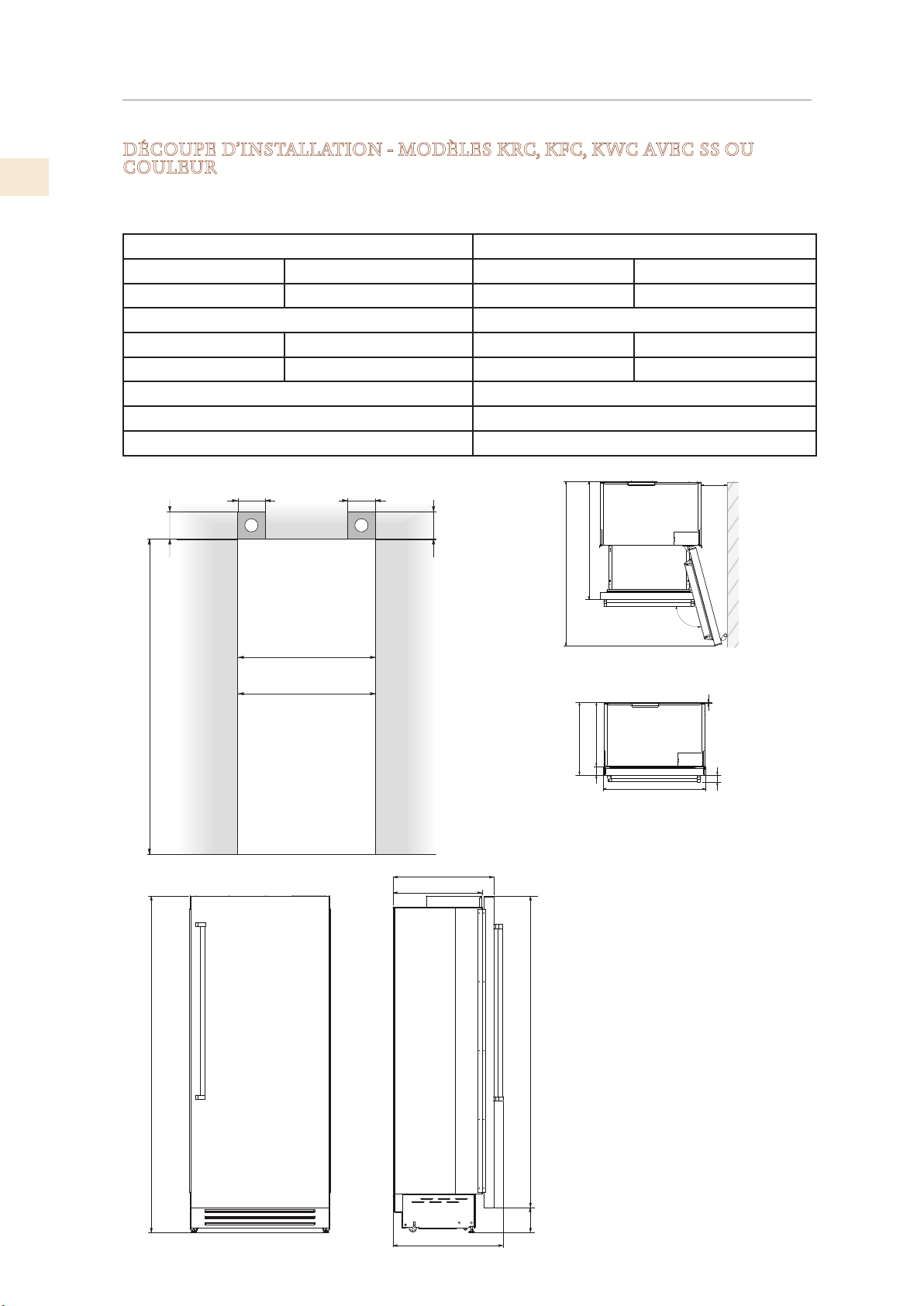
5-½ po [140]
4 po [100]
min 84 po [2134]
4 po [100]
5-½ po [140]
30: 52-⁄" [1325]
30: 7-¾" [195]
83-½ po [2120 ] + 1 po [25]
25-
¼ po [640]
+ 1 po [25]
FR
LIEU ET PRÉPARATION
(SUITE)
DÉCOUPE D’INSTALLATION - MODÈLES KRC, KFC, KWC AVEC SS OU
COULEUR
RÉFRIGÉRATEURS ET CONGÉLATEURS À COLONNE DE 24 PO ET 30 PO
COLONNE À VIN DE 24 PO ET RÉFRIGÉRATEUR DE 24 PO AVEC VIN
Hauteur de l’encastrement Largeur de l’encastrement
Modèles de 24 po 84 po [2134 mm] Modèles de 24 po 23-3/4 po [600 mm]
Modèles de 30 po 84 po [2134 mm] Modèles de 30 po 29-5/8 po [750 mm]
Encombrement avec porte ouverte Largeur
Modèles de 24 po 46-1/4 po [1175 mm] Modèles de 24 po 23-5/8 po [599 mm]
Modèles de 30 po 52-1/8 po [1325 mm] Modèles de 30 po 29-1/2 po [749 mm]
Angle d’ouverture de la porte 105°
Hauteur 83-1/2 po [2120 mm] + 1 po [25 mm]
Profondeur 25 po [635]
24: 6-¼" [160]
A A
30: 29-⁄ po [750]
24: 23-¾ po [600]
22-
¼ po [565]
40-¼" [1021]
24: 46-¼" [1175]
22-¼" [565]
25-¼" [640]
30: 29- 1/2" [749]
3" [75]
24: 23- 5/8" [599]
105°
⁄" [ 10]
2-¼" [58]
© 2019 Hestan Commercial Corporation
9
27
½po [
698 ]
77-¾ po [1974]
5-¾ po [146]
Page 53
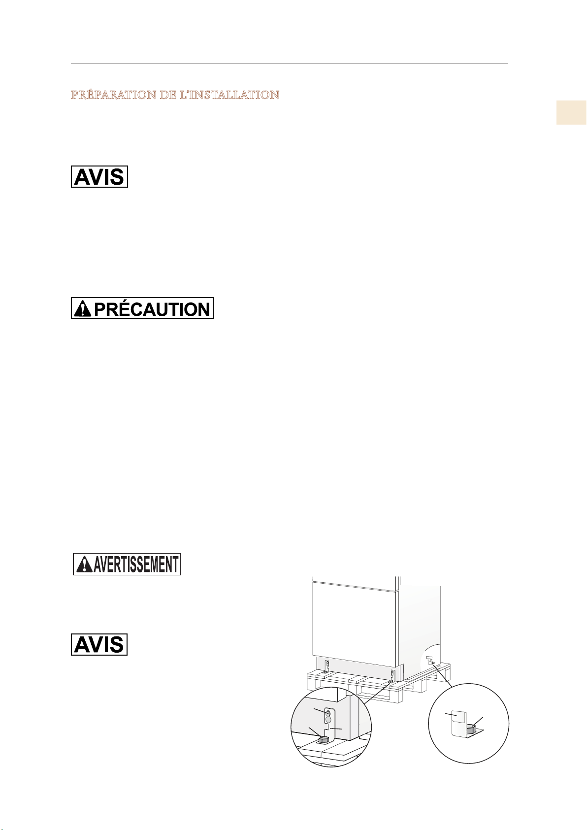
LIEU ET PRÉPARATION
2
1
4
1
3
(SUITE)
PRÉPARATION DE L’INSTALLATION
Transport vers le site d’installation et déballage
S’agissant d’un appareil lourd et volumineux, vérifiez, avant de le transporter, l’accès à
l’emplacement où il sera installé (taille de la porte, espace de manœuvre dans la cage d’escalier,
etc.).
La garniture latérale, les poignées de porte (modèles non OV), le gril et éventuellement d’autres
articles seront emballés à l’arrière de l’appareil. Assurez-vous de retirer ces articles et leurs
emballages avant de retirer l’appareil de la palette.
L’appareil est fixé à la base de l’emballage (palette) à l’aide de quatre boulons qui peuvent être
retirés à l’aide d’une clé de 17 mm (11/16 po).
Il est recommandé d’utiliser un transpalette ou un autre dispositif de transport pour déplacer
l’appareil sur le site d’installation, et uniquement à ce stade pour retirer la base de l’emballage.
L’appareil doit toujours être transporté en position verticale. Si cela n’est pas possible,
transportez l’appareil à l’arrière.
FR
Une fois sur le site d’installation, l’appareil, équipé de quatre roues, peut être retiré de la palette
et placé dans la zone d’installation.
Retirer l’appareil de la palette:
1) Retirez les quatre boulons (1) fixant l’appareil à la palette à l’aide d’une vis 17 mm (11/16 po)
clé.
2) Retirez les supports de retenue arrière (4).
3) Pour retirer les supports de fixation avant (3), dévisser les boulons de réglage de roue arrière
(2) d’un ou deux tours à l’aide d’une clé de 13 mm. Cela dégagera les supports de fixation
avant (3) afin que vous puissiez les retirer.
4) À l’arrière de l’appareil et à l’aide d’un chariot manuel approprié, retirez l’appareil et posezle sur le sol.
Faites très attention à ne pas endommager les sols. Les sols délicats doivent être protégés avec
du contreplaqué, du carton dur ou similaire.
L’appareil est très lourd.
Faites très attention lors de la manipulation
pour éviter les blessures.
L’appareil doit toujours être transporté en
position verticale.
Évitez à tout prix de le pencher sur sa face
avant.
© 2019 Hestan Commercial Corporation
10
Page 54
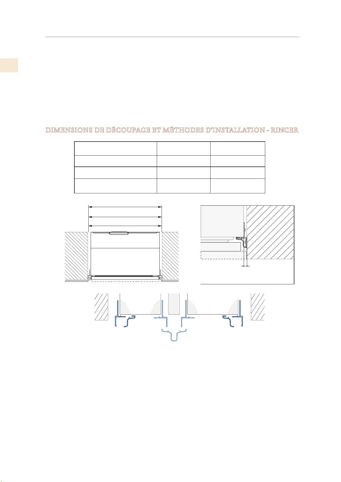
LIEU ET PRÉPARATION
A A
B
Articles inclus supplémentaires
(SUITE)
FR
Plusieurs articles sont expédiés à l’intérieur de l’appareil. Ceux-ci inclus:
• Manuels
• Matériel d’installation des panneaux (modèles -OV)
• Raccord de raccordement à l’eau, filtre à eau (modèles avec machine à glaçons)
• Supports anti-renversement
• Articles de soin - chiffon et / ou éponge à lustrer.
DIMENSIONS DE DÉCOUPAGE ET MÉTHODES D’INSTALLATION - RINCER
Modèles
KRB36
Colonnes de 30 po (KxCx30)
Colonnes de 24 po et Vin
(KxCx24, KRWx24)
36 po: 35-1/2 po [900 ]
30 po: 29-5/8 po [750]
24 po: 23-3/4 po [600]
Coupé
35-1/2 po [900 mm]
29-5/8 po [750 mm]
23-3/4 po [600 mm]
Largeur du panneau
35-1/4 po [897 mm]
29-3/8 po [747 mm]
23-1/2 po [597 mm]
A
1/4 po [6,5]
C
A. Kit de connexion latérale (accessoire inclus)
AKRLJK (pour les modèles KRB, KRC, KFC, KWC et KRW)
AKRLJKP (pour les modèles KRP)
B. Kit de connexion central, requis pour joindre 2 unités
(Non inclus - doit être commandé en tant qu’accessoire séparé)
AKRCJK-OV (pour les modèles KRB, KRC, KFC, KWC et KRW avec façade superposée)
AKRCJK (pour les modèles KRB, KRC, KFC, KWC et KRW avec façade en acier inoxydable ou
coloré
AKRCJKP (pour les modèles KRP)
C. Kit anti-condensation AKRACPP, nécessaire pour connecter deux unités KRP.
(Non inclus - doit être commandé en tant qu’accessoire séparé)
11
© 2019 Hestan Commercial Corporation
Page 55
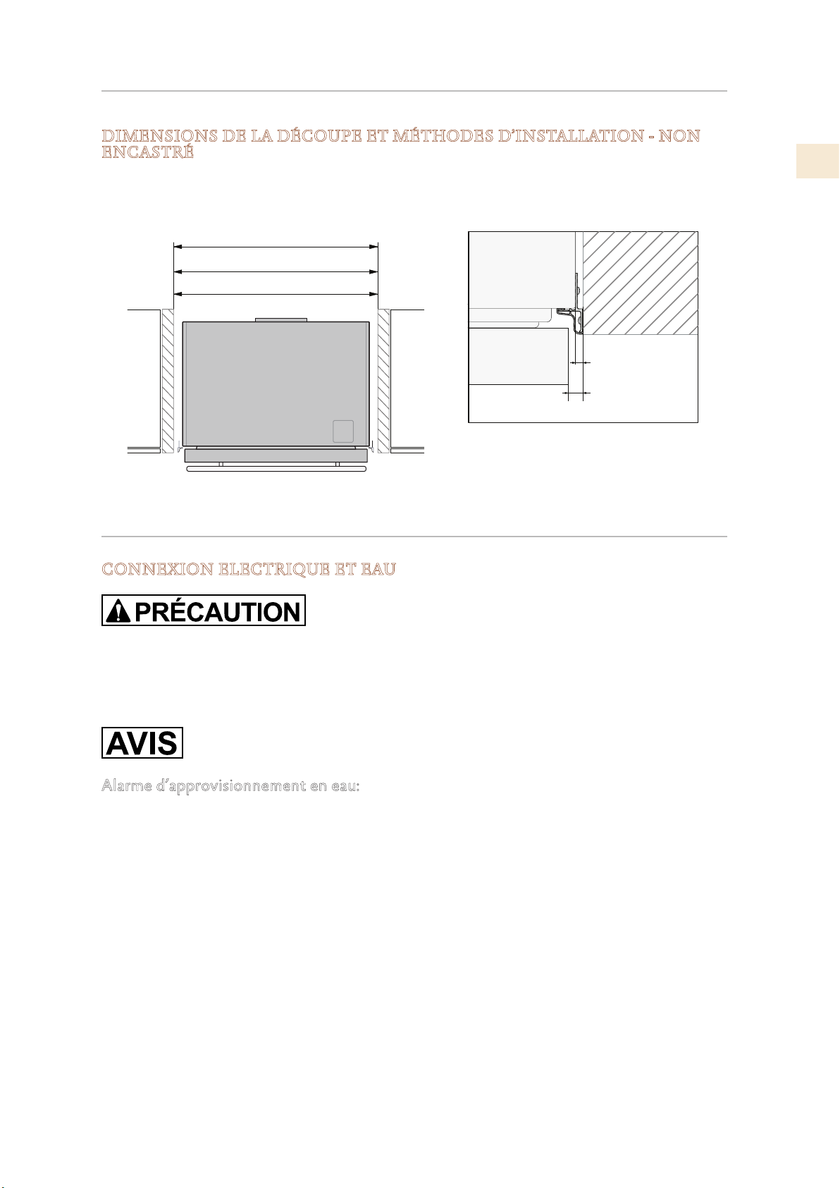
LIEU ET PRÉPARATION
A A
36: 35-1/2 po [900 ]
(SUITE)
DIMENSIONS DE LA DÉCOUPE ET MÉTHODES D’INSTALLATION - NON
ENCASTRÉ
En cas d’installation non encastré, la même garniture latérale est utilisée et la même largeur de
découpe est requise.
30: 29-5/8 po [750]
24: 23-3/4 po [600 ]
A
1/4 po [6,5]
3/8 po [10]
A: Kit de connexion latérale / latérale
FR
CONNECTER
CONNEXION ELECTRIQUE ET EAU
N’utilisez pas de rallonges ni d’adaptateurs multiples pour la connexion au bloc d’alimentation.
N’utilisez pas de rallonges ni d’adaptateurs.
Le filtre Hestan intégré ne peut rendre aucune eau potable, il doit être utilisé avec une eau déjà
adaptée à la consommation humaine.
Alarme d’approvisionnement en eau:
Si vous devez couper l’alimentation en eau une fois que l’appareil est complètement installé,
connecté à l’alimentation en eau (le cas échéant) et opérationnel, appuyez sur le commutateur
Marche / Arrêt pour éteindre l’appareil d’abord pour éviter une alarme «NO WATER IN».
© 2019 Hestan Commercial Corporation
12
Page 56
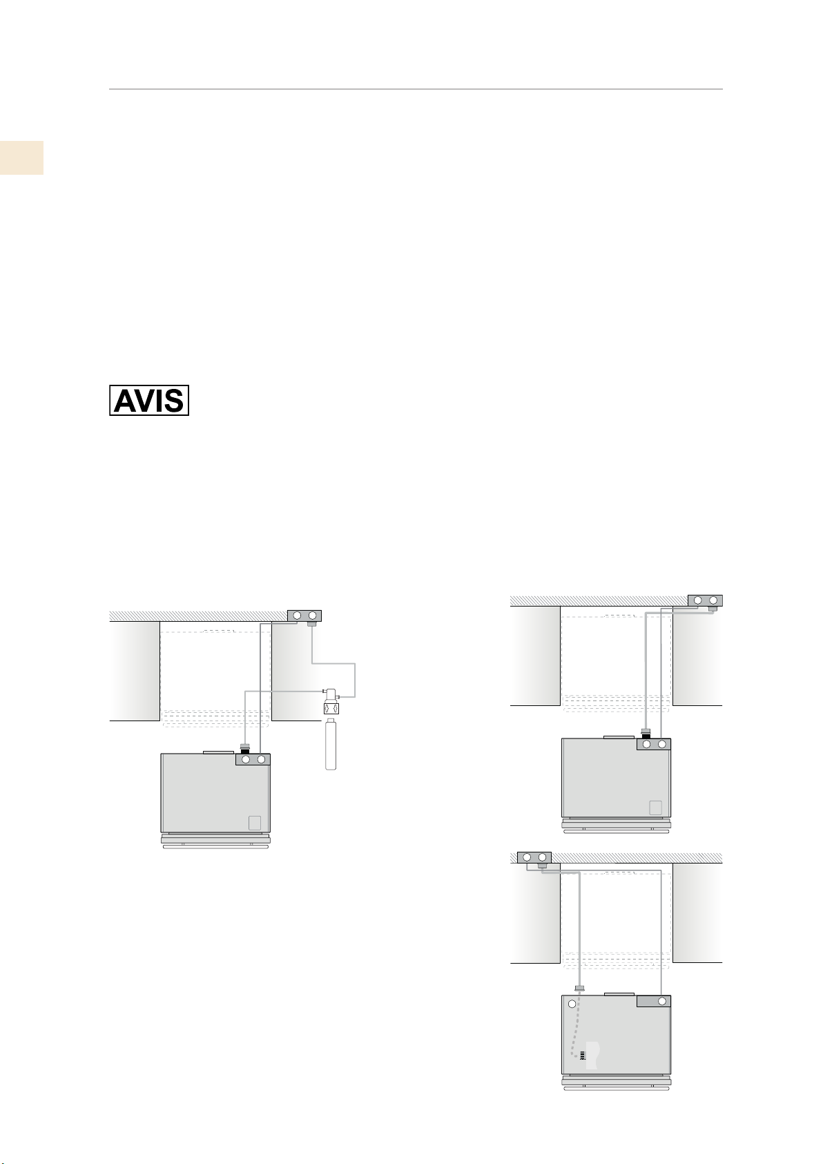
FR
CONNECTER
(SUITE)
Les appareils sont livrés de l'usine pour fonctionner à 110V-120V AC - 60Hz (États-Unis et
Canada). Ils sont fournis avec un cordon d'alimentation et une fiche appropriés à brancher sur
une prise 15A appropriée (États-Unis et Canada) dotée d'une mise à la terre efficace.
Un disjoncteur doit également être installé et doit être facilement accessible afin qu'il puisse
être facilement désactivé avant toute installation ou maintenance.
Pour se connecter au système d'alimentation en eau (pour les appareils équipés de machines à
glaçons), une conduite d'eau de 1/4 ”avec vanne d'arrêt accessible doit être fournie.
L'appareil est fourni avec un coude d'adaptation d'eau adapté à la pression d'eau élevée et
conforme aux réglementations en vigueur. La cartouche de filtre à eau fournie avec l'appareil
doit être installée conformément aux instructions fournies.
Les modèles KRP et KRB ont le filtre à eau monté au-dessus du compartiment du réfrigérateur,
au-dessus du panneau de verre.
Les modèles KFC sont fournis avec un filtre à eau qui doit être monté à l'extérieur de l'unité.
Utilisez uniquement le nouvel adaptateur fourni avec l'appareil. La connexion du solénoïde
sur l’appareil a un diamètre de 3/4 po mais est filetée métrique. Un connecteur fileté de
tuyau d'arrosage standard, tel qu'un tuyau en acier inoxydable tressé, que l'on trouve dans les
quincailleries typiques, risque de dénuder ou d'endommager les filets de l'électrovanne. Utilisez
uniquement l’adaptateur coudé à raccordement rapide fourni de 1/4 po pour raccorder une
conduite d'eau de source en cuivre ou en polyéthylène de 1/4 po à l'appareil.
Longueur du cordon électrique: 78-3/4 po [2000 mm]
Longueur de la conduite de raccordement à l’eau: 98-3/8 po [2500 mm]
Voir page suivante pour plus d’informations.
W
Modèles KFC
E
E
Filtre à eau à
monter dans une
W
armoire
E
W
W
Modèles KRB
E
W
E
13
© 2019 Hestan Commercial Corporation
W
Modèles KRP
Raccordement
d'eau dans la base
de l'appareil près
de l'avant
E
Page 57
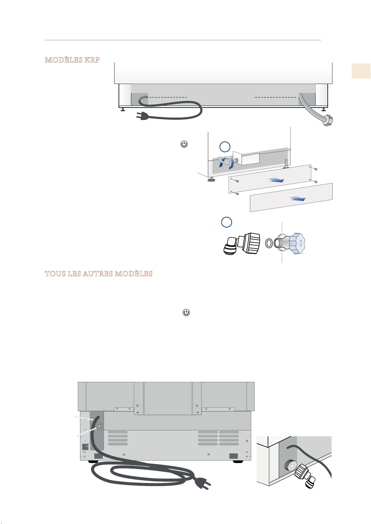
CONNECTER
MODÈLES KRP
Connectez-vous
comme suit:
(SUITE)
Arrière de l’appareil
FR
Déroulez le cordon
électrique et branchezle directement à la prise
murale.
Observez l’affichage
des informations. Si
l’appareil n’est pas en veille ou si des lumières sont
allumées, appuyez sur le bouton marche / arrêt
pendant trois secondes pour l’éteindre.
Connectez la conduite d’eau au raccord fileté situé à
la base de l’appareil. (1)
Placez l’autre extrémité du tuyau (2) sur le robinet
d’eau, utilisez les joints fournis dans la trousse du
propriétaire.
Serrez fermement à la main - un outil / une clé ne
devrait pas être nécessaire pour sceller correctement.
Ouvrez l’eau et assurez-vous que toutes les
connexions ne fuient pas avant de pousser l’appareil
dans l’ouverture.
Raccordement HydrauliqueBranchement Électrique
Avant de
l’appareil
1
2
TOUS LES AUTRES MODÈLES
Connectez-vous comme suit:
Déroulez le cordon électrique et branchez-le directement à la prise murale.
Observez l’affichage des informations. Si l’appareil n’est pas en veille ou si des lumières sont
allumées, appuyez sur le bouton Marche / Arrêt pour l’éteindre.
Enfoncez complètement la conduite d’eau source 1/4 po dans le raccord coudé, puis vissez
l’adaptateur coudé sur le solénoïde à l’arrière de l’appareil.
Serrez fermement à la main - un outil ou une clé ne devrait pas être nécessaire pour sceller
correctement.
Ouvrez l’eau et assurez-vous que toutes les connexions ne fuient pas avant de pousser l’appareil
dans la niche.
Arrière de l’appareil
Branchement
Électrique
Raccordement
Hydraulique
© 2019 Hestan Commercial Corporation
14
Page 58
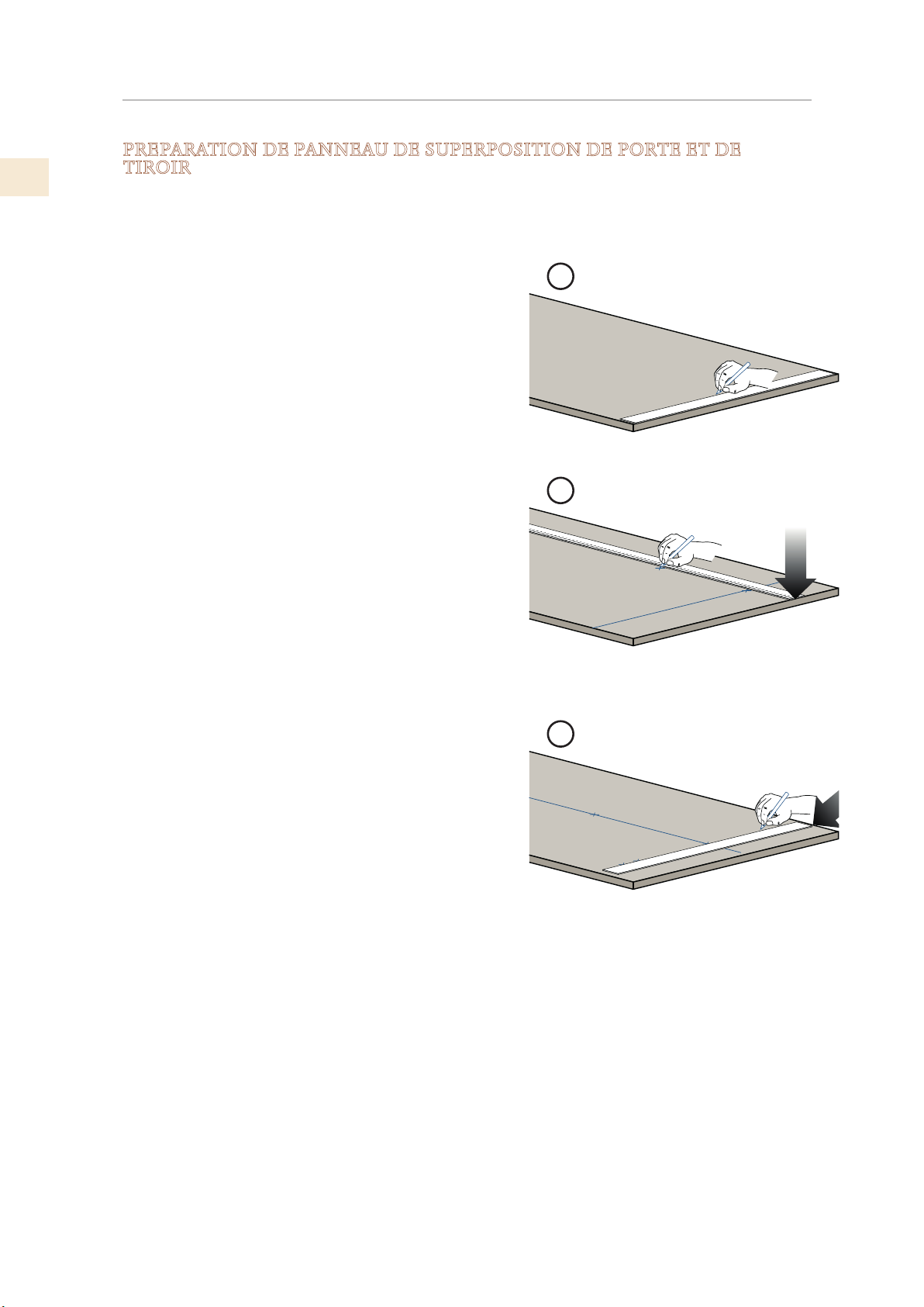
FR
PRÉPARATION DES PANNEAUX DÉCORATIFS
PREPARATION DE PANNEAU DE SUPERPOSITION DE PORTE ET DE
TIROIR
Panneaux décoratifs:
Les dimensions des panneaux sont indiquées dans le tableau et les dessins des pages suivantes.
Pour aligner les panneaux avec d’autres structures de cuisine, les dimensions peuvent être
ajustées si le panneau de porte doit être plus haut que le
bord supérieur de la porte du réfrigérateur et / ou si le
panneau de tiroir doit être plus bas que le bord du tiroir.
Les panneaux doivent être montés à l’aide de supports
spéciaux qui se fixent aux dispositifs réglables de la
porte et du tiroir et à des supports fixant et orientant le
panneau dans le sens vertical.
Les entretoises, les supports et les vis de fixation sont
fournis avec l’appareil et doivent être appliqués sur le
panneau comme indiqué.
1
Procédure de mise en page:
Pour préparer les panneaux à monter sur l’appareil,
procédez comme suit, en travaillant au dos du panneau.
Panneau de porte
1) Tracez une ligne divisant la largeur du panneau en
deux. (1)
2) En commençant par le bord inférieur du panneau,
marquez l’emplacement des supports. (2)
3) En suivant le tableau correspondant, marquez le
trou externe puis le trou interne. (3)
2
3
15
© 2019 Hestan Commercial Corporation
Page 59
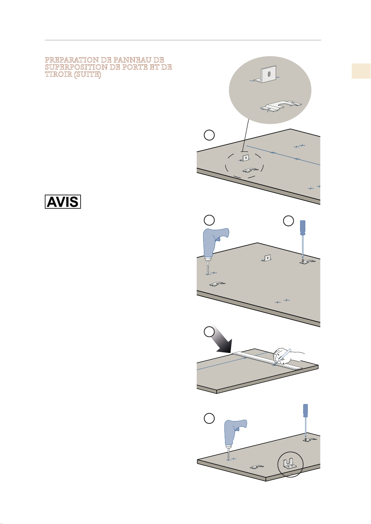
PRÉPARATION DES PANNEAUX DÉCORATIFS
PREPARATION DE PANNEAU DE
SUPERPOSITION DE PORTE ET DE
TIROIR (SUITE)
Monter les supports
4) Positionnez les supports sur chaque jeu de
marques pour vous assurer qu’ils sont alignés. (4)
(SUITE)
FR
Notez que le support est monté avec la bride vers le
haut de la porte.
• Si nécessaire, percez des trous de départ dans le
panneau. (5)
(Utilisez un arrêt de la perceuse pour éviter de
percer ou d’endommager la surface de finition.)
Le kit d’installation comprend des vis de 5/8 po . Si
le panneau n’est pas sensiblement plus épais que 5/8
po , vous aurez besoin de vis plus courtes.
5) Vissez les supports en place. (6)
4
5
6
Panneau de tiroir
Lorsque vous préparez le panneau de tiroir, suivez
les mêmes instructions que pour le panneau de
porte, mais assurez-vous que les mesures sont prises
en partant du bord supérieur. (7)
Le support est placé dans le sens opposé du support
du panneau de porte. (Comparez les images 4 et 8)
7
8
© 2019 Hestan Commercial Corporation
16
Page 60
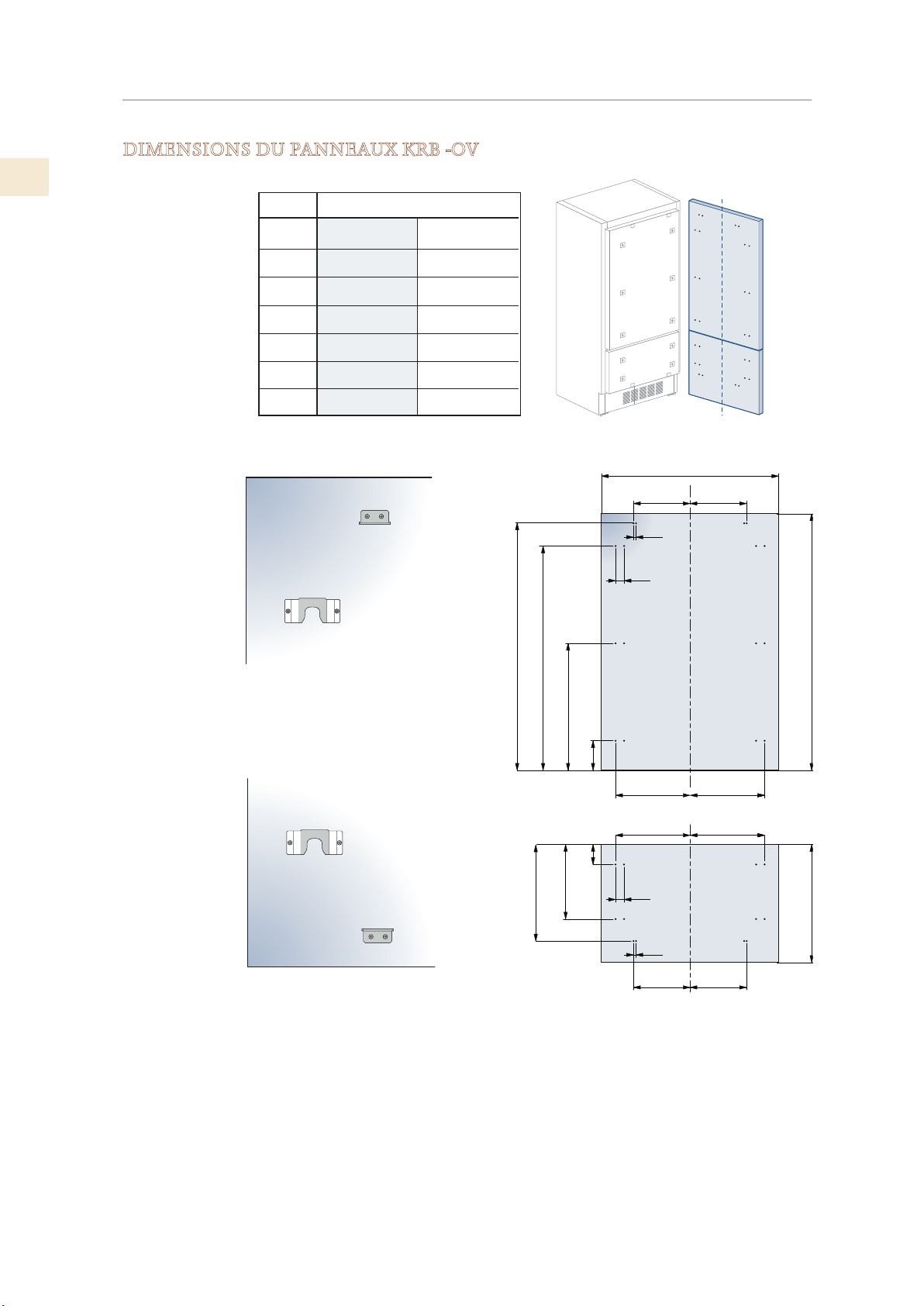
FR
PRÉPARATION DES PANNEAUX DÉCORATIFS
DIMENSIONS DU PANNEAUX KRB -OV
KRB36-OV
Charnière
Droite
35-1/4 po [897]
10-1/4 po [261]
A
B
Charnière
Gauche
35-1/4 po [897]
14 po [355,5]
(SUITE)
C
D
E
F / G
10-1/4 po [261]
16-1/2 po [418]
15-1/4 po [386]
14 po [354,5]
14 po [355,5]
15-1/4 po [386]
16-1/2 po [418]
14 po [354,5]
50-5/8 po [1285]
45-3/4 po [1163]
[157]
26 po [660]
6-1/4 po
A
B C
½ po
[13]
1-3/8 po
[34]
D E
min 54-3/4 po [1390]
17
© 2019 Hestan Commercial Corporation
20 po [507,5]
15-1⁄8 po [382]
4 po [100]
D E
1-3⁄8 po
[34]
½ po [13]
F G
max 25 po [635]
Page 61
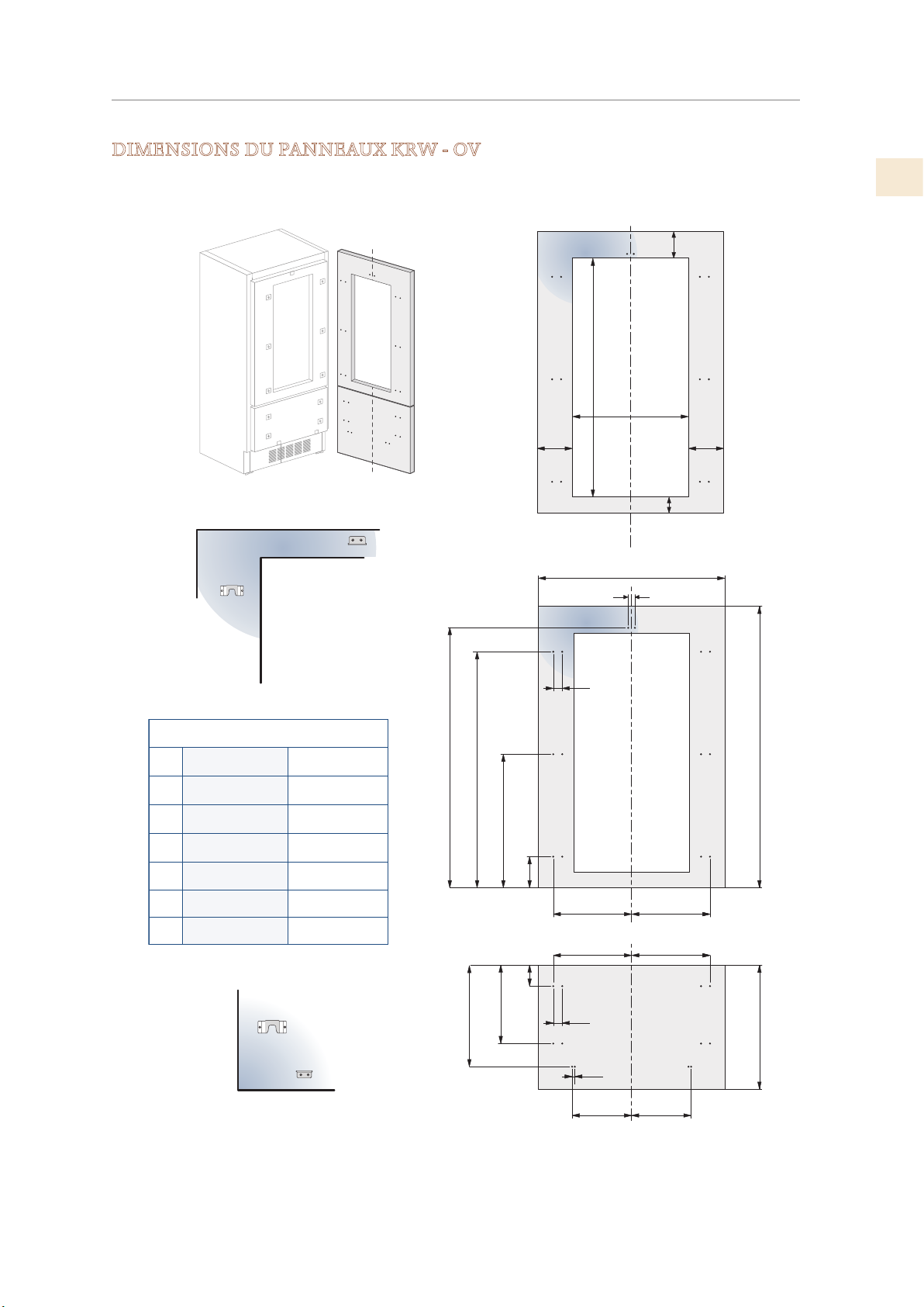
PRÉPARATION DES PANNEAUX DÉCORATIFS
DIMENSIONS DU PANNEAUX KRW - OV
3⁄8 po [1075
42
(SUITE)
FR
< 7-7⁄8 po
[200]
A
D
E
F / G
H
I
KRW24
Charnière
Gauche
23-½ po [597]
10-7/8 po [276,5]
9-3/8 po [236,5]
8 po [203,5]
10-5/8 po [270,5]
9-1/8 po [230,5]
Charnière
Droite
23-½ po [597]
9-3/8 po [236,5]
10-7/8 po [276,5]
8 po [203,5]
9-1/8 po [230,5]
10-5/8 po [270,5]
50-5/8 po [1286]
20 po [507,5]
45-3/8 po [1152,5]
25-5/8 po [650,5]
[382]
-1⁄8 po
15
5 -3⁄8 po
[135]
5-7/8 po [148,5]
[100]
4 po
24 po: 12-7⁄8 po
¼ po
[6,5
]
1-3⁄8" [34]
H I
D E
1-3⁄8 po
[34]
½ po
[13]
F G
A
[327]
4- ½ po
[115]
¼ po
[6,5
5 -3⁄8 po
[135]
]
[1390]
min 54- ¾ po
max 25 po [635]
© 2019 Hestan Commercial Corporation
18
Page 62
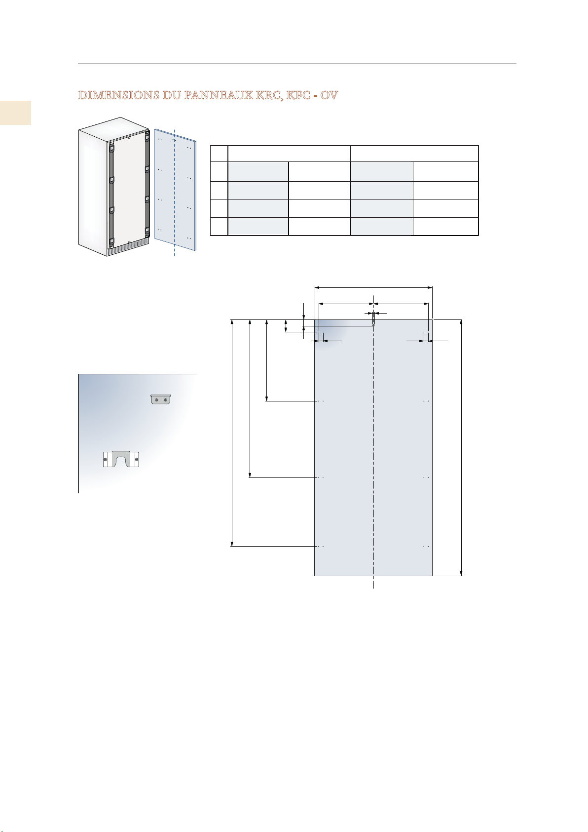
FR
PRÉPARATION DES PANNEAUX DÉCORATIFS
DIMENSIONS DU PANNEAUX KRC, KFC - OV
(SUITE)
1
30 po
Charnière
Gauche
A 23-1/2 po [597]
29-3/8 po [747]
B
13-1/2 po [343]
C
13-1/2 po [343] 13-1/2 po [343]
27-1/4 po [690.5]
50 po [1271.5]
Charnière
Droite
29-3/8 po [747] 23-1/2 po [597]
13-1/2 po [343]
1-3/8 po
[34]
6-1/2 po [165]
4-3/8 po [112]
Charnière
Gauche
10-7/8 po [276.5]
10-1/2 po [268]
A
B C
24 po
Charnière
Droite
10-1/2 po [268]
10-7/8 po [276.5]
1/2 po [13]
1-3/8 po
[34]
70-3/4 po [1797]
min 76-1/8 po [1933]
19
© 2019 Hestan Commercial Corporation
Page 63
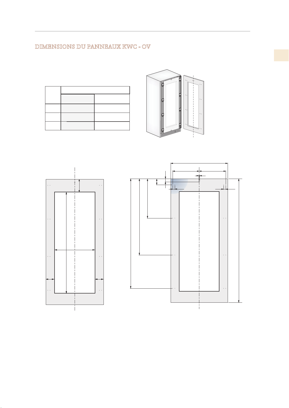
PRÉPARATION DES PANNEAUX DÉCORATIFS
DIMENSIONS DU PANNEAUX KWC - OV
panneau de porte
1
KWCR/L24-OV MODELS
A
Charnière
Gauche
23-1/2 po [597]
Charnière
Droite
23-1/2 po [597]
(SUITE)
FR
B
C
10-7⁄8 po [276,5]
min 7-7⁄8 po
po [62 1572]
24: 12-7/8 po
[ 327]
10-1/2 po [268]
10-7/8 po [276,5]10-1/2 po [268]
[200]
27-1/4 po [690,5]
50 po [1271,5]
70-3/4 po [1797]
6-1/2 po [165]
4-3/8 po [112]
B C
1/2 po [13]
A
1/2 po [13]
1/2 po [13]
min 76-1/8 po [1933]
5-3/8 po
[135]
5-3/8 po
[135]
© 2019 Hestan Commercial Corporation
20
Page 64
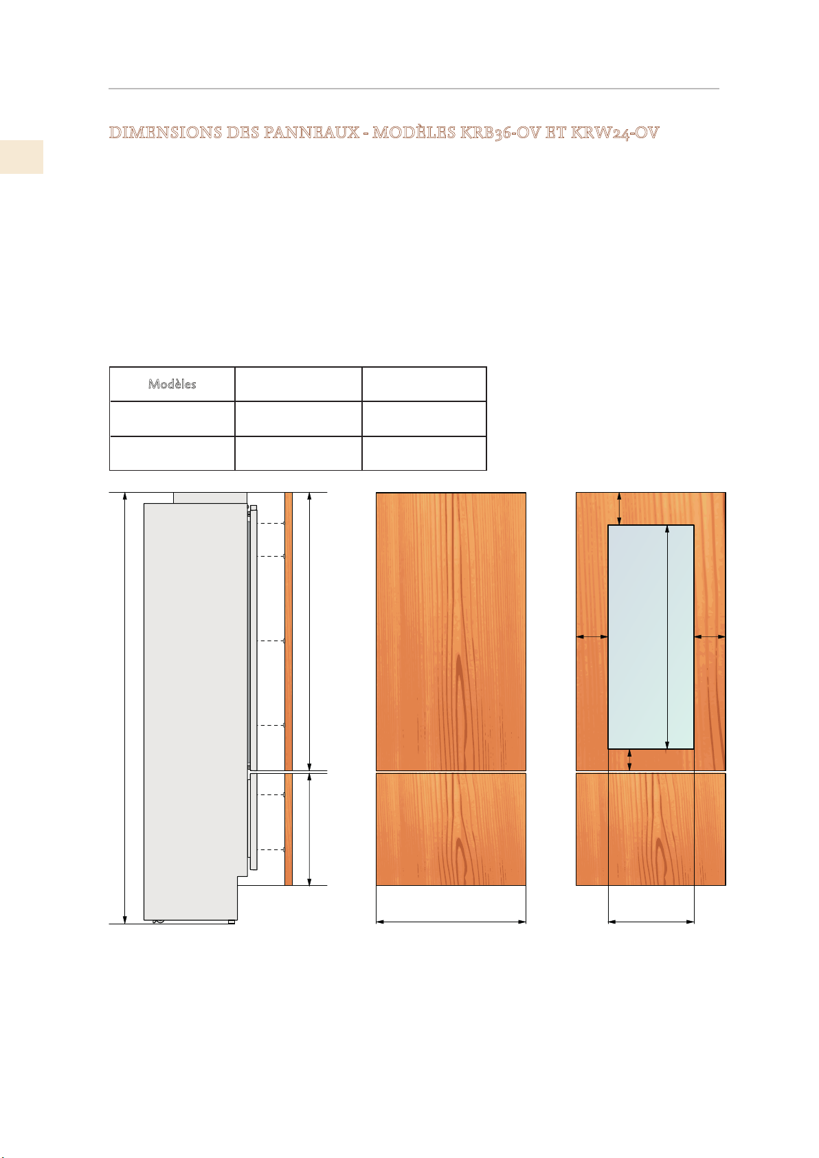
FR
83-1/2 po [2121] + 1 po [25]
PRÉPARATION DES PANNEAUX DÉCORATIFS
(SUITE)
DIMENSIONS DES PANNEAUX - MODÈLES KRB36-OV ET KRW24-OV
Les panneaux peuvent avoir une épaisseur comprise entre 3/4 po [18mm] et 1-1 / 8“ [28 mm].
Les panneaux de porte peuvent peser au maximum 23 kg (51 lb) et les panneaux de tiroir, au
maximum poids de 25 livres [11kg].
Le dépassement de ces poids pourrait annuler votre garantie pour tout problème de service
pouvant être attribué à des panneaux en surpoids.
Le mécanisme de charnière des réfrigérateurs Hestan est considéré comme étant «à jeu zéro».
Les largeurs de porte et de tiroir spécifiées ci-dessous supposent que la largeur de niche
minimale est utilisée et qu’une ouverture de 1/8 po [3.5mm] est souhaitée autour des panneaux.
Ajustez les dimensions de votre panneau en fonction de vos propres critères de conception
en tenant compte de votre largeur de niche et de votre visibilité. Le nombre de révélations /
espaces minimaux ne doit pas être inférieur à 1,5 mm
odèles
M
KRBR/L36-OV
KRWR/L24-OV
Largeur de porte /
tiroir A
35-1/4 po [897]
54-3/4 po [1390]
1/8 po [3]
Largeur de découpe
de porte B
N/A
12-7/8 po [327]23-1/2 po [597]
min 7-7/8 po [200]
5 -3/8 po
[135]
5 -3/8 po
[135]
42-3/8 po [1075]
4-1/2 po [115]
21
Exemple:
84 po hauteur de découpe
36 po largeur de découpe
4 po hauteur des pieds
1/8 po distance désirée tout autour
© 2019 Hestan Commercial Corporation
max 25 po [635 ]
min 21-1/4 po [540]
A B
Panneau de porte:
Détermination de la taille du panneau du tiroir:
Largeur: 35-3/4 po
Hauteur: 84 po − 1/8 po − 54-3/4 po − 1/8 po − 4 po = 25 po
Si vous voulez une hauteur de 6 po avec des écarts de 1/8 po,
la hauteur du panneau du tiroir inférieur sera de 23 po.
Largeur: 35-3/4 po
Hauteur: 54-3/4 po
Page 65
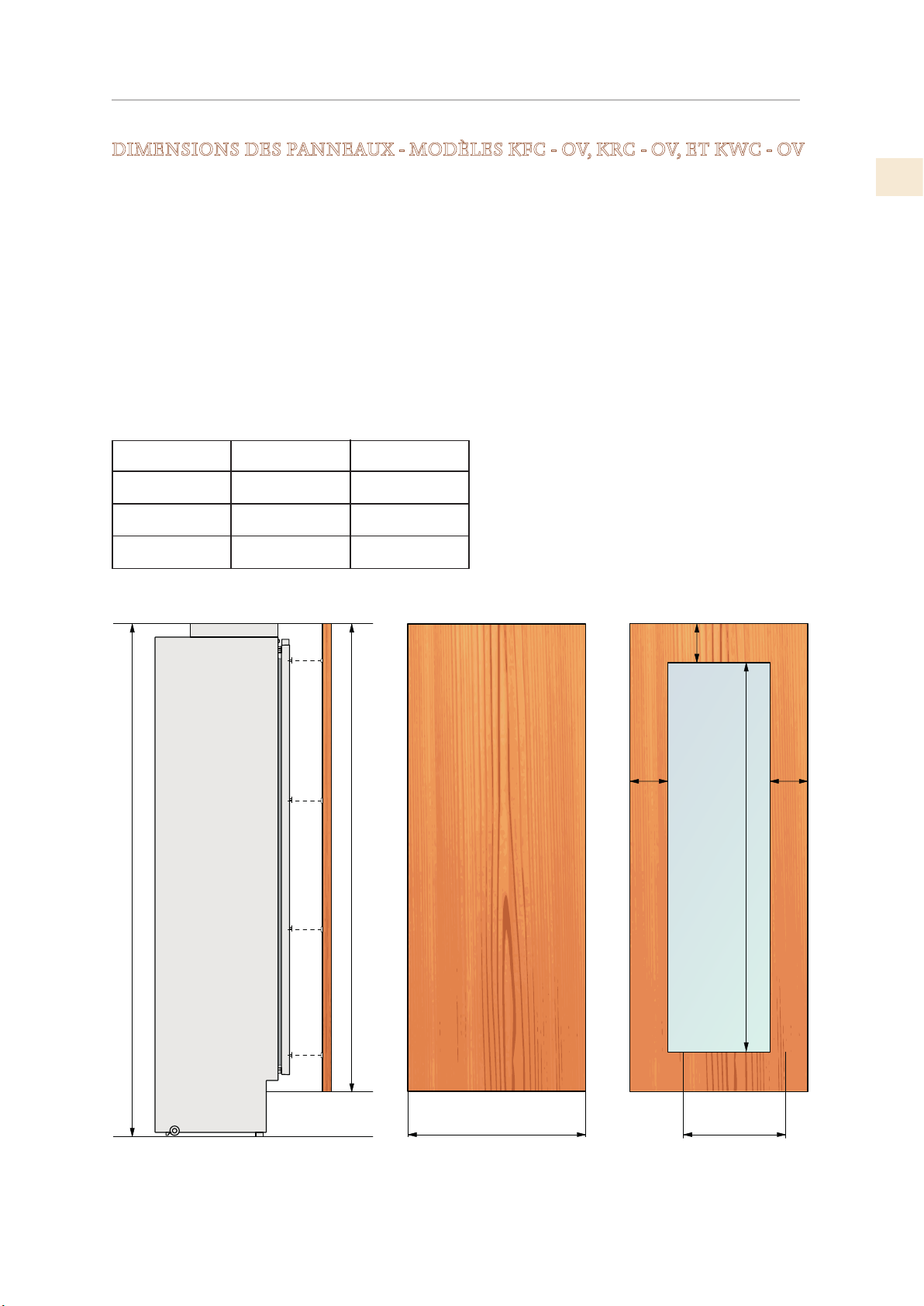
PRÉPARATION DES PANNEAUX DÉCORATIFS
83-1/2 po [2121] + 1 po [25]
5-3/8 po
(SUITE)
DIMENSIONS DES PANNEAUX - MODÈLES KFC - OV, KRC - OV, ET KWC - OV
Les panneaux peuvent avoir une épaisseur comprise entre 3/4 po [18mm] et 1-1/8 po [28 mm].
Les panneaux de porte peuvent peser au maximum 51 livres [23 kg] et les panneaux de tiroir, au
maximum poids de 25 livres [11 kg].
Le dépassement de ces poids pourrait annuler votre garantie pour tout problème de service
pouvant être attribué à des panneaux en surpoids.
Le mécanisme de charnière des réfrigérateurs Hestan est considéré comme étant «à jeu zéro». Les
largeurs de porte et de tiroir spécifiées ci-dessous supposent que la largeur de niche minimale est
utilisée et qu’une ouverture de 1/8 po [3.5mm] est souhaitée autour des panneaux. Ajustez les
dimensions de votre panneau en fonction de vos propres critères de conception en tenant compte
de votre largeur de niche et de votre visibilité. Le nombre de révélations / espaces minimaux ne
doit pas être inférieur à 1,5 mm
FR
Modèles
KRC 30, KFC 30
KRC 24, KFC 24
KWCR/L24-OV 23-1/2 po [597]
Largeur de la porte
et de tiroir
29-3/8 po [747]
23-1/2 po [597]
A
Porte: Largeur de
la coupure
12-7/8 po [327]
B
N/A
N/A
min 7-7⁄8 po [200]
5-3/8 po
[135]
[135]
62 po [1572 ]
min 76-1/8 po [1933]
max 79-7/8 po [2028]
A B
© 2019 Hestan Commercial Corporation
22
Page 66
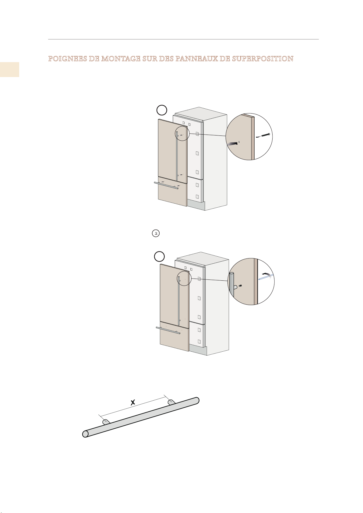
FR
PRÉPARATION DES PANNEAUX DÉCORATIFS
(SUITE)
POIGNEES DE MONTAGE SUR DES PANNEAUX DE SUPERPOSITION
Les poignées doivent être montées sur le panneau décoratif de la
porte et du grand bac avant que les panneaux ne soient fixés au
réfrigérateur.
1
Positionner la poignée au niveau du trou sur le côté avant du panneau:
insérer par l’arrière du panneau la vis fournie, à travers le trou,
et la visser à la poignée.
Poignées non fournies avec les modèles Overlay (-OV)
(exemple de poignée montré)
2
2
23
Mesurer avec précision la distance entre
centres de trou pour les dimensions correctes à appliquer
avant de percer les trous de fixation dans votre panneaux.
© 2019 Hestan Commercial Corporation
Page 67
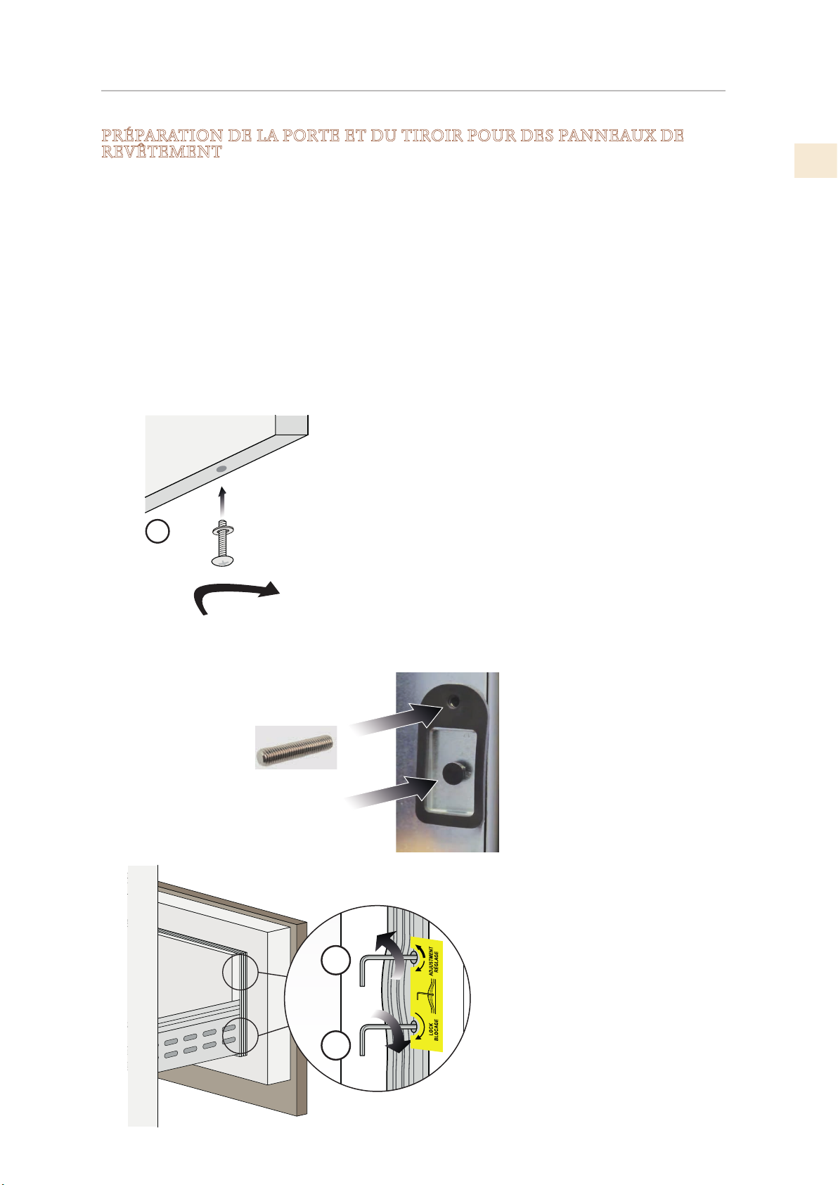
PRÉPARATION DES PANNEAUX DÉCORATIFS
(4) Vis de réglage en profondeur
(SUITE)
PRÉPARATION DE LA PORTE ET DU TIROIR POUR DES PANNEAUX DE
REVÊTEMENT
Les vis de réglage et les boulons de suspension doivent être vissés dans la porte (et le tiroir, le cas
échéant) avant de poser les panneaux décoratifs.
Installez les vis de réglage vertical au fond du tiroir (le cas échéant) 2-3 tours de profondeur. Les vis
de réglage vertical du panneau de porte s’installent après l’application du panneau de porte.
Installez un boulon de suspension dans chaque renfoncement - seulement 2-3 tours de profondeur.
Installez une vis de réglage de la profondeur dans les trous situés au-dessus ou au-dessous de
chaque évidement. L’ouverture de la clé passe en premier afin que les réglages puissent être
effectués du côté de l’appareil sur la porte. Ceux-ci doivent être vissés presque au ras du joint qui
les entoure.
Les vis de réglage de la profondeur peuvent être mises en place et vissées à la main. Si nécessaire,
vous pouvez utiliser une clé Allen de 4 mm de l’intérieur de la porte ou du tiroir. Tirez doucement
le joint de la porte pour faire apparaître le trou de la vis.
REMARQUE: Les vis de réglage
Emplacement des vis
de réglage vertical
1
dans le tiroir
Vis de réglage vertical
vertical de la porte sont
installées après la suspension
du panneau sur la porte.
FR
Vis de réglage de profondeur:
Installer avec prise vers l'appareil
Boulon de suspension
4
5
- celles-ci permettent de
régler l’espacement entre la
porte et le panneau
(5) Boulons de suspension -
ils fixent le panneau
© 2019 Hestan Commercial Corporation
24
Page 68
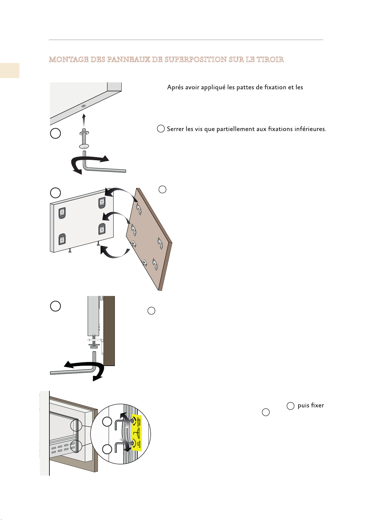
FR
de
PRÉPARATION DES PANNEAUX DÉCORATIFS
(SUITE)
MONTAGE DES PANNEAUX DE SUPERPOSITION SUR LE TIROIR
équerres aux panne -aux, commencer l’installation par
le tiroir du bas.
1
1
2
2
Fixer le panneau aux support du tiroir à partir des crans
de la partie inférieure de réglage.
3
3
À ce point il est possible de régler la hauteur du panneau
avec les crans interieurs pour s’aligner, en serrant ou
déssérant la vis. En tenant la vis un peu desserée, déplacer à
droite ou à gauche le pan-neau pour le centrer au panneau
la porte ou au reste des meubles de la cuisine.
Alignement en profondeur en travaillant de l’intérieur du
tiroir et après avoir soulevé le joint magnétique, rapprocher ou
éloigner le panneau du tiroir à travers les trous
le panneau toujours à travers les trous.
4
5
5
4
25
© 2019 Hestan Commercial Corporation
Page 69
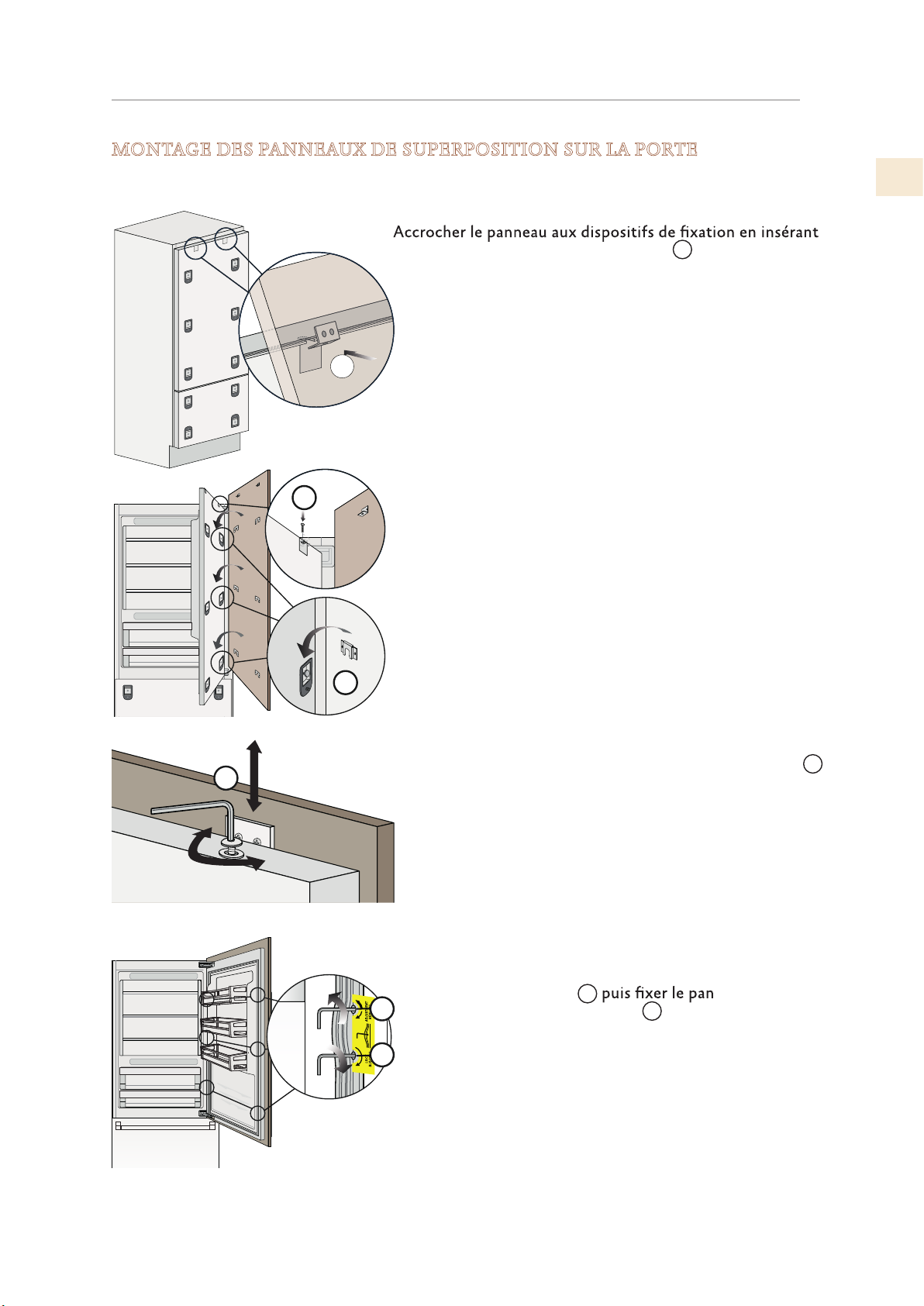
PRÉPARATION DES PANNEAUX DÉCORATIFS
(SUITE)
MONTAGE DES PANNEAUX DE SUPERPOSITION SUR LA PORTE
FR
dans les crans d’alignement supérieurs.
6
Une fois le panneau accroché à tous les boulons de suspen-
6
sion, installez les deux vis de réglage vertical.
Voir (9) ci-dessous.
7
À ce stade, l'alignement entre le panneau et les armoires
adjacentes peut être ajusté à l'aide des supports d'alignement et des supports (7) et (8).
8
9
vissant ou en dévissant la vis à l’équerre.
Alignement en profondeur en travaillant de l’intérieur
de la porte à après avoir soulevé le joint magnétique,
rapprocher ou éloigner le panneau à sa place toutjours
Alignement vertical: soulever ou abaisser le panneau 9 en
10
11
à travers les trous
10
toujours à travers les trous.
11
-ne au à sa place
© 2019 Hestan Commercial Corporation
26
Page 70
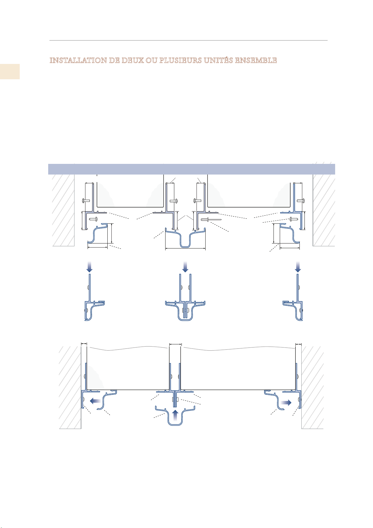
FR
INSTALLATION FINALE
INSTALLATION DE DEUX OU PLUSIEURS UNITÉS ENSEMBLE
L’installation de deux unités ou plus en tant que composants intégrés côte à côte nécessite un
kit de connexion centralisée.
(Non inclus - doit être commandé en tant qu’accessoire séparé)
AKRCJK (pour les modèles KRB, KRC, KFC, KWC et KRW)
AKRCJK-OV (pour les modèles KRB, KRC, KFC, KWC and KRW avec panneaux superposés
AKRCJKP (pour les modèles KRP)
L’appareil est livré avec des connecteurs latéraux de chaque côté. Le kit de connecteurs
comprend des connecteurs pour l’arrière des unités, des attaches et un cache pour la jonction
centrale.
Montage des profilés latéraux et centraux
mur ou
meubles
1/4 po [6.5]
3/4 po [20]
7/8 po [22]
Appareil
A
7/8 po [22]
B
1/4 po
[6.5]
Appareil
3/4 po [20]
D
C
A
E
1-3/4 po [44.4]
7/8 po
B
1/4 po [6.5]
mur ou
meubles
3/4 po [20]
[22]
7/8 po [22]
Mur ou
meubles
1/4 po [6.5]
A
A Connecteur latéral en aluminium
B Cache de garniture - côté
Connecteur latéral
A
en aluminium
B
Cache de garniture côté
C
Cache de garniture centre
Appareil
A
B B
C
C Cache de garniture - centre
D
Attaches de connecteur
D
central
E
Fixation des connecteurs
latéraux à l'armoire - (fourni
par l'installateur / le client)
Appareil
A
D
Attaches
1/4 po [6.5]1/2 po [13]
Mur ou
meubles
A
27
© 2019 Hestan Commercial Corporation
Page 71
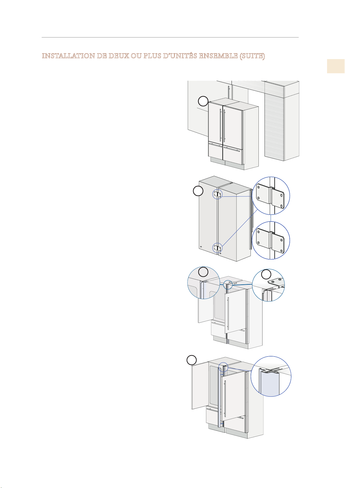
INSTALLATION FINALE
(SUITE)
INSTALLATION DE DEUX OU PLUS D’UNITÉS ENSEMBLE (SUITE)
Positionnez les deux unités de manière à ce qu’elles puissent, une fois réunies, être repliées dans
leur position finale.
1) Pour les unités KRP, placez l’isolant anticondensation selon ses instructions.
FR
2) Placez les unités côte à côte et vérifiez le
nivellement. Les deux unités doivent être à la
même hauteur avant de se connecter. (Article 3,
cette page)
Les connecteurs latéraux doivent juste toucher le
long de leur longueur.
3) À l’arrière, montez les supports de jonction sur
une unité, puis sur l’autre. (Article 2, cette page)
4) La partie supérieure peut également nécessiter
un connecteur. Installez si nécessaire / fourni.
(Article4, cette page)
5) À l’avant, attachez les connecteurs centraux
en aluminium à l’aide des attaches fournies.
(ArticleD, page précédente)
6) Enclenchez le capot de garniture central.
(Article 5, cette page):
DÉPLACER DEUX UNITÉS EN POSITION
FINALE
Assurez-vous que les connecteurs latéraux
correspondent à la largeur de la découpe. Voir
"VÉRIFIER / AJUSTER LA GARNITURE LATÉRALE" à
la page 30.
1
2
3
4
La procédure est la même que pour une seule unité.
Voir page suivante.
5
© 2019 Hestan Commercial Corporation
28
Page 72
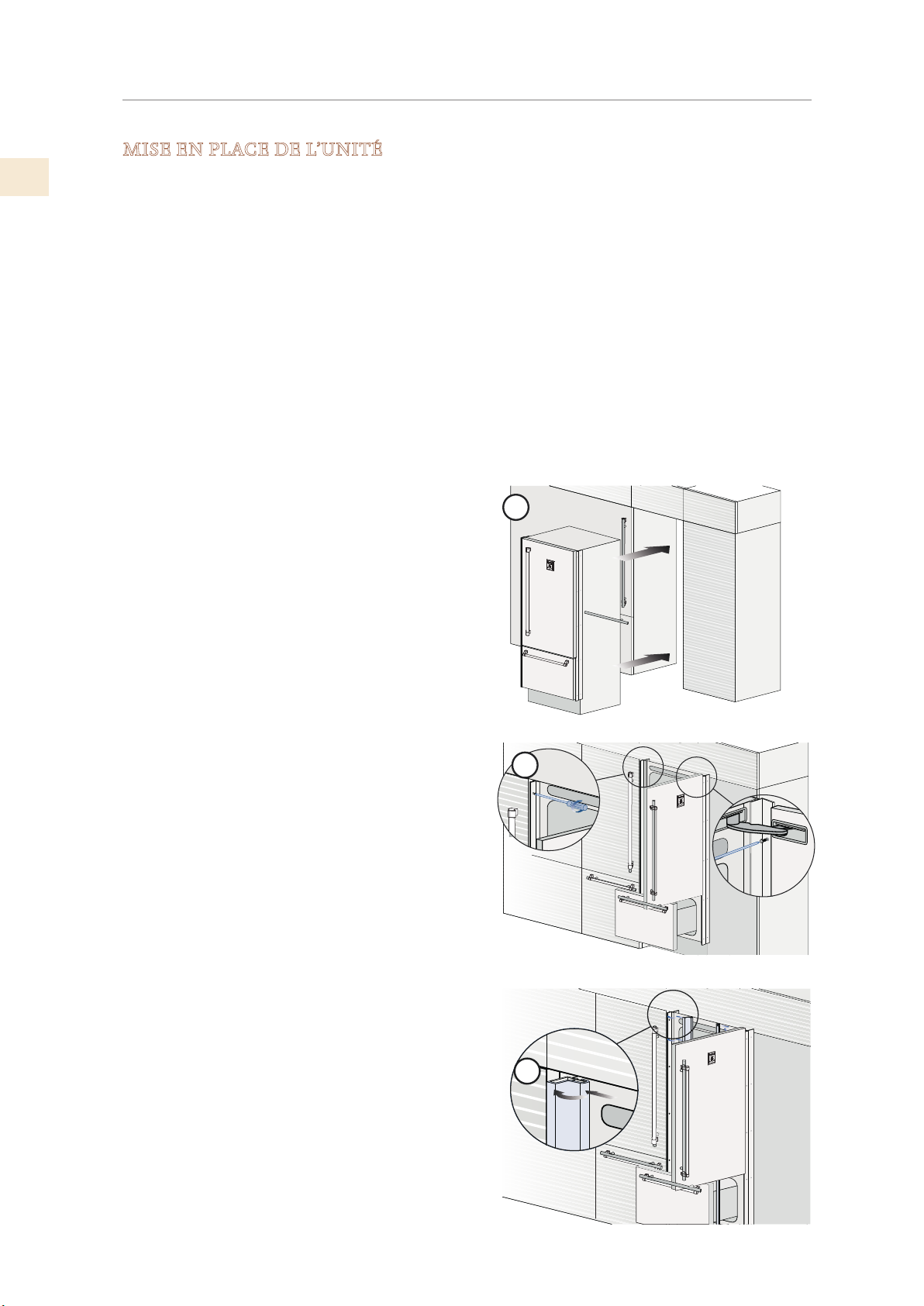
FR
INSTALLATION FINALE
(SUITE)
MISE EN PLACE DE L’UNITÉ
Des connecteurs latéraux avec des garnitures décoratives sont fournis pour fixer l’appareil aux
armoires adjacentes.
Assurez-vous que les connecteurs latéraux correspondent à la largeur de la découpe. Voir
"VÉRIFIER / AJUSTER LA GARNITURE LATÉRALE" à la page 30.
Tous les modèles sauf KRP: L'appareil n'a pas besoin de conduit de ventilation dans le boîtier
pour le refroidissement.
KRP: Voir "DÉCOUPE D’INSTALLATION - MODÈLES KRP" on page 5 pour les exigences de
ventilation.
Installez toujours les panneaux avant sur la porte et le tiroir avant de placer l’unité dans sa
position finale à l’intérieur du boîtier.
1) Déplacez l’unité dans sa position finale
2) Vérifiez la mise à niveau de l’appareil, en ajustant les pieds et les roues pour le corriger si
nécessaire.
3) Fixez l’appareil aux armoires adjacentes à l’aide
des profilés latéraux. (2)
Pour faciliter cette opération, maintenez la
porte et le tiroir ouverts.
4) Montez les capots de garniture en les insérant
d’abord latéralement (3), puis en appuyant
fermement jusqu’à ce que vous entendiez un
«clic».
1
2
29
3
© 2019 Hestan Commercial Corporation
Page 73
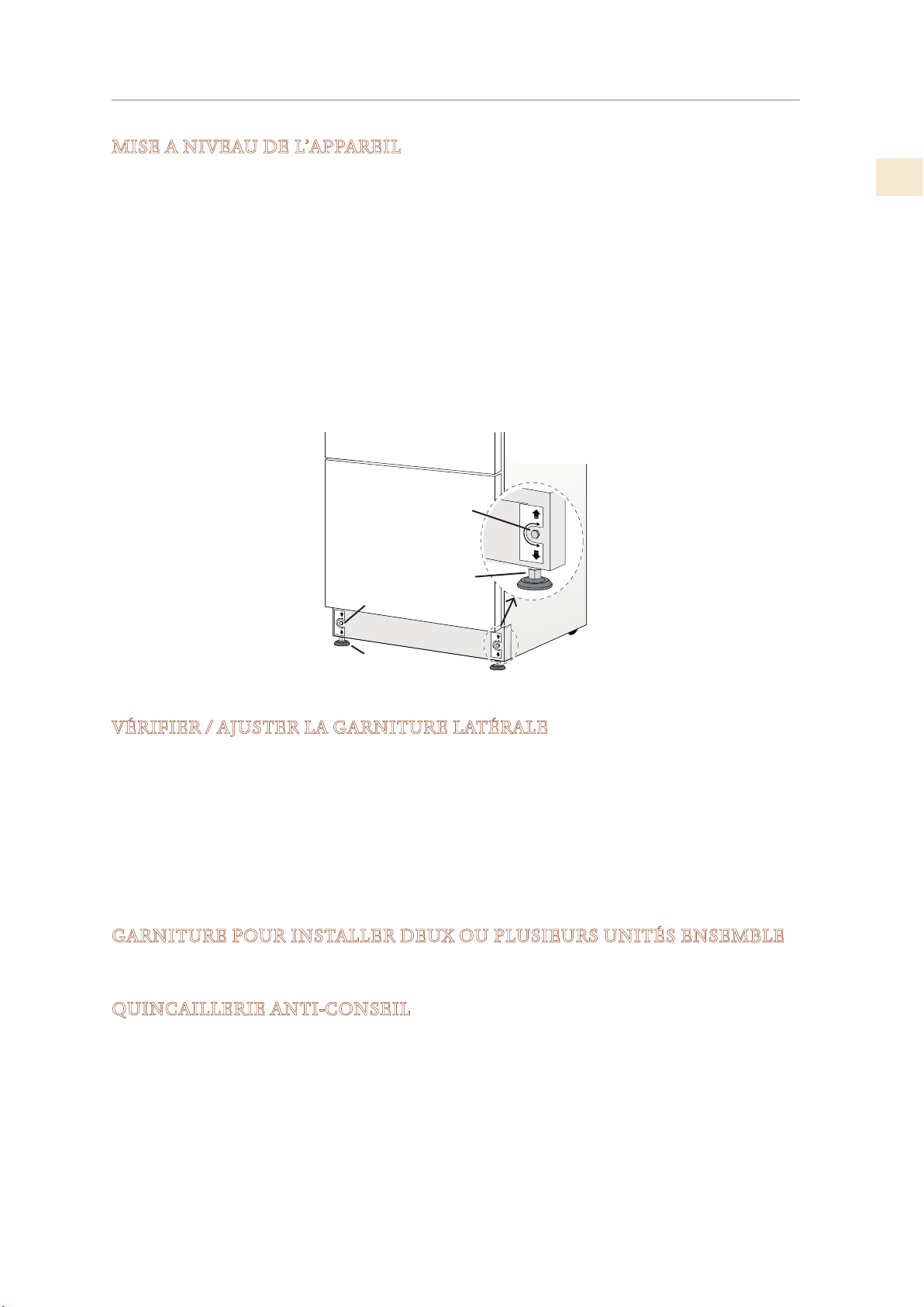
INSTALLATION FINALE
(SUITE)
MISE A NIVEAU DE L’APPAREIL
Mettez l’appareil à niveau après l’avoir mis en place.
Réglez le niveau de l’appareil à l’aide des pieds de mise à niveau avant et des roues arrière
réglables.
Niveau comme suit:
1) Retirez la grille inférieure si nécessaire (elle est maintenue en position par des aimants)
2) Réglez l’avant avec les pieds réglables (1) à l’aide d’une clé plate ou d’une clé plate 17 mm
(ou 11/16 po).
3) Réglez la hauteur de l’arrière en tournant les boulons de réglage avant (2) dans le sens
des aiguilles d’une montre ou dans le sens contraire des aiguilles d’une montre, selon les
besoins.
4) Réinstallez le grille.
2
FR
1
2
1
VÉRIFIER / AJUSTER LA GARNITURE LATÉRALE
La garniture latérale standard convient à une ouverture aux dimensions spécifiées, comme
indiqué à la page 5 et aux pages suivantes.
Si la découpe est un peu plus large ou pas parfaitement carrée, la garniture peut être ajustée
pour s’adapter.
La méthode suggérée consiste à utiliser des entretoises entre l’appareil et la bande de garniture
sous chacune des cinq vis fixant chaque bande de garniture. Des rondelles plates peuvent être
utilisées comme entretoises, choisissez les épaisseurs appropriées.
Ce réglage doit être effectué avant que des panneaux décoratifs ne soient montés sur les portes.
GARNITURE POUR INSTALLER DEUX OU PLUSIEURS UNITÉS ENSEMBLE
Lors de l’installation d’unités côte à côte, un kit de finition spécial doit être utilisé sur les côtés
opposés. Voir “INSTALLATION DE DEUX OU PLUSIEURS UNITÉS ENSEMBLE” à la page 28.
QUINCAILLERIE ANTI-CONSEIL
L’installation du matériel antibasculement est détaillée à la page 31 et doit être terminée une
fois l’appareil en place et nivelé.
Cependant, vous voudrez peut-être faire les préparatifs avant de monter des panneaux
décoratifs.
© 2019 Hestan Commercial Corporation
30
Page 74
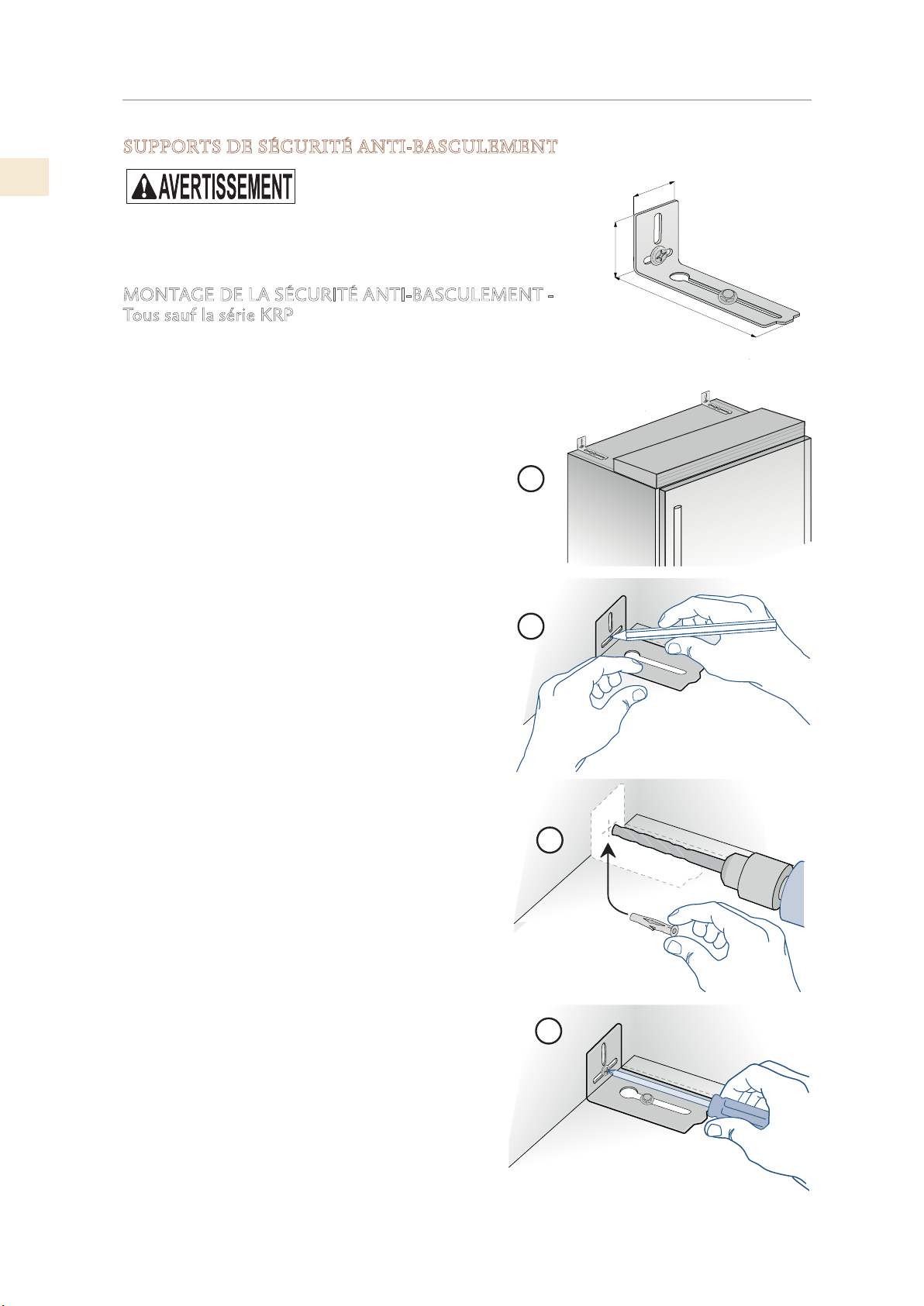
FR
1-5/8 po [45]
INSTALLATION FINALE
(SUITE)
SUPPORTS DE SÉCURITÉ ANTI-BASCULEMENT
Pour éviter tout risque de renversement de l’appareil, il est
impératif de fixer l’appareil au mur à l’aide des deux supports
fournis.
MONTAGE DE LA SÉCURITÉ ANTI-BASCULEMENT Tous sauf la série KRP
Lors de l’utilisation des supports anti-renversement, ils doivent
être appliqués comme indiqué à l’aide des vis et des ancrages
muraux fournis.
1) Trouvez les trous de montage sur le dessus de
l’appareil et déterminez comment le support doit
s’aligner sur le mur.
2) Marquez le mur où les trous sont nécessaires.
3) Percez le mur avec un foret de 5/16 po [8 mm] et
insérez l’ancrage mural.
1
2-3/8 po [59]
6 po [152]
4) Positionnez le support et fixez-le d’abord à
l’appareil, puis au mur.
De plus, il est suggéré:
• Les garnitures latérales des deux côtés doivent
être fixées à l’unité à l’aide des vis fournies.
• Les garnitures latérales doivent être vissées aux
armoires à tous les points de fixation fournis.
• L’armoire doit être solidement fixée au mur pour
assurer la stabilité de l’appareil.
Lorsque deux unités sont installées ensemble, les
supports anti-basculement sont nécessaires pour
chacune d’elles.
De plus, le kit de raccordement approprié doit être
installé et les unités doivent être fixées aux armoires
adjacentes au moyen des garnitures latérales, comme
ci-dessus.
2
3
31
4
© 2019 Hestan Commercial Corporation
Page 75
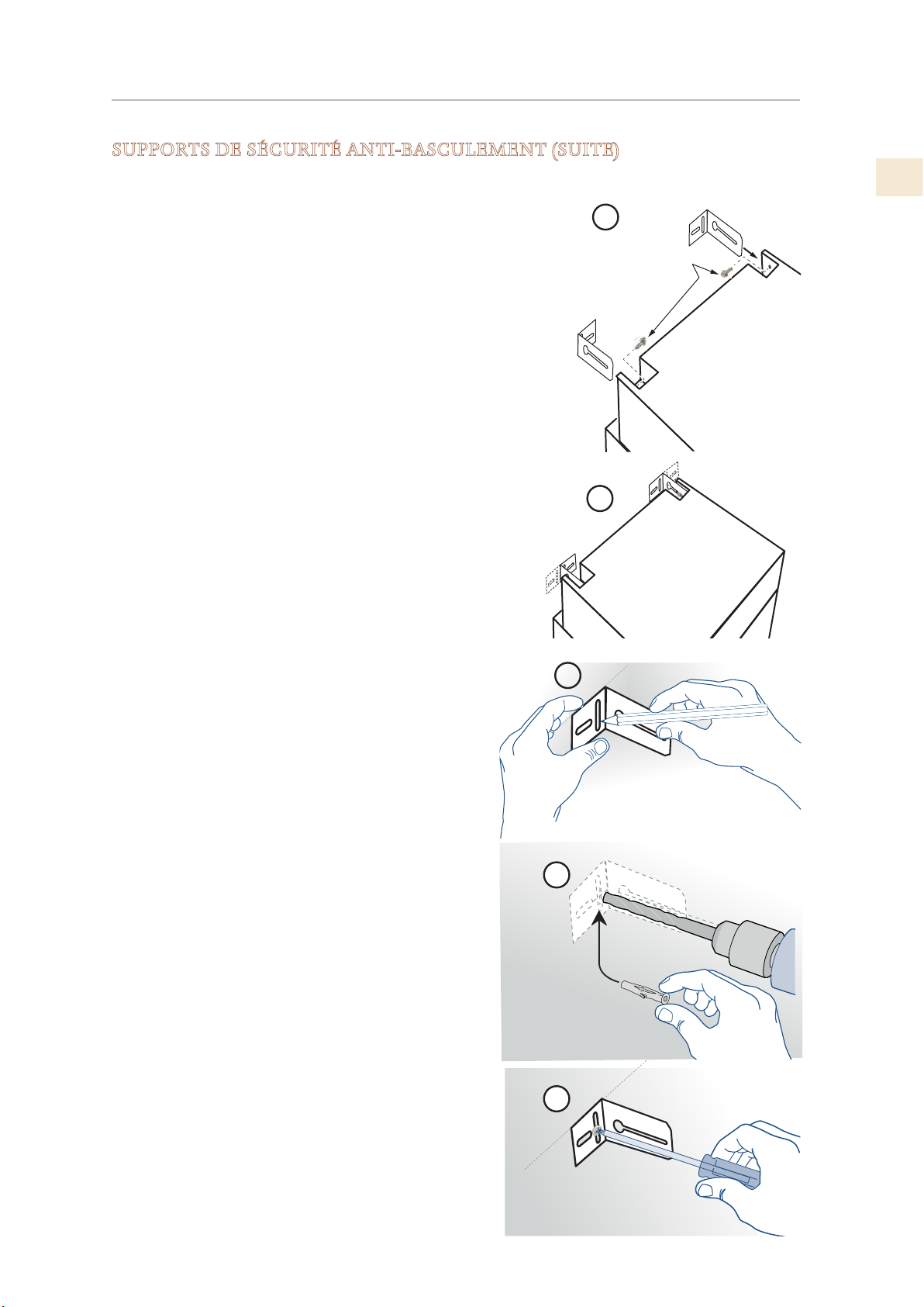
INSTALLATION FINALE
(SUITE)
SUPPORTS DE SÉCURITÉ ANTI-BASCULEMENT (SUITE)
MONTAGE DE LA SUPPORTS- Série KRP
Pour éviter tout risque de renversement de l’appareil, il
est impératif de fixer l’appareil au mur à l’aide des deux
supports fournis.
1) L’appareil a une vis en place où chaque support va se
fixer. (Voir la figure à droite.) Retirez les vis et mettezles de côté.
2) Déterminez l’emplacement des supports et marquez
le mur en conséquence. Notez que les supports
peuvent être installés face ou vers l’intérieur, selon vos
préférences.
3) Éloignez l’appareil du mur et marquez l’emplacement
des trous.
1
Vis de montage
anti-basculement
FR
4) Percez le mur avec un foret de 5/16 po [8 mm] et
insérez l’ancrage mural.
5) Montez le support sur le mur, puis mettez
l’appareil en position et fixez-le à l’aide des vis
retenues de (1) ci-dessus.
De plus, il est suggéré:
• Les garnitures latérales des deux côtés doivent
être fixées à l’unité à l’aide des vis fournies.
• Les garnitures latérales doivent être vissées aux
armoires à tous les points de fixation fournis.
• L’armoire doit être solidement fixée au mur pour
assurer la stabilité de l’appareil.
Lorsque deux unités sont installées ensemble, les
supports anti-basculement sont nécessaires pour
chacune d’elles.
De plus, le kit de raccordement approprié doit être
installé et les unités doivent être fixées aux armoires
adjacentes au moyen des garnitures latérales, comme
ci-dessus.
2
3
4
5
© 2019 Hestan Commercial Corporation
32
Page 76
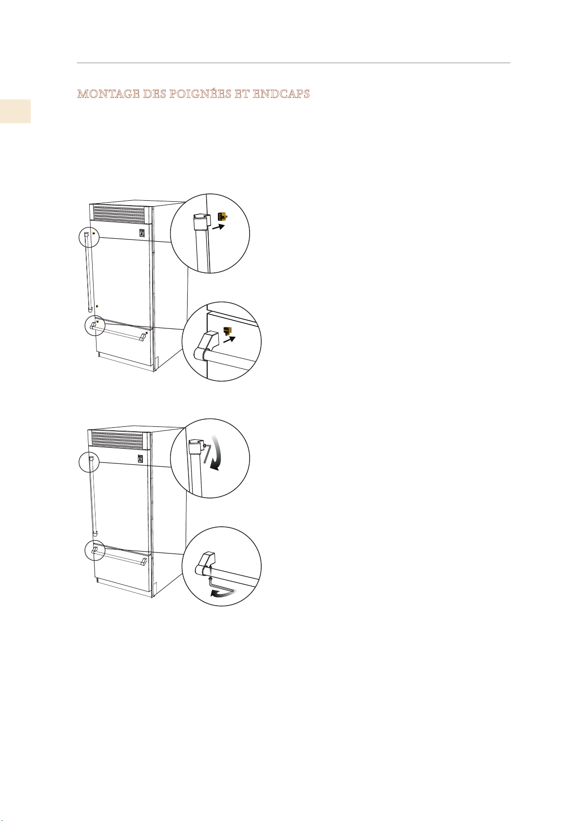
FR
INSTALLATION FINALE
(SUITE)
MONTAGE DES POIGNÉES ET ENDCAPS
Les poignées et les embouts sont fournis avec tous les modèles en acier inoxydable et en couleur.
Les poignées sont situées dans un emballage protecteur, scotché à l’arrière du réfrigérateur.
Retirez les poignées avant déplacer le réfrigérateur dans sa découpe ou son ouverture. Les
embouts sont situés dans une boîte en carton à l’intérieur du réfrigérateur.
Il est recommandé que deux personnes travaillent ensemble pour assembler et appliquer les
poignées et embouts. Suivez les étapes ci-dessous pour terminer le processus de montage.
Insérez la poignée dans les embouts et positionnez
les embouts sur les supports qui sont pré-montés sur
la porte et le tiroir.
• Utilisation Attention à ne pas rayer la surface de
la porte.
• Il est recommandé de une personne tient la
poignée et les embouts en position pendant que
la deuxième personne insère les vis de réglage
fournies pour fixer manipuler.
Les vis de réglage fournies se trouvent dans la boîte
avec les embouts. À l’aide d’une clé hexagonale de
1/8 po (2,5 mm), insérez la vis de réglage dans le trou
dans le bouchon et resserrer soigneusement. Le
bouchon est alors correctement fixé à la porte / tiroir.
Répétez cette étape pour l’autre embouts.
33
© 2019 Hestan Commercial Corporation
Page 77
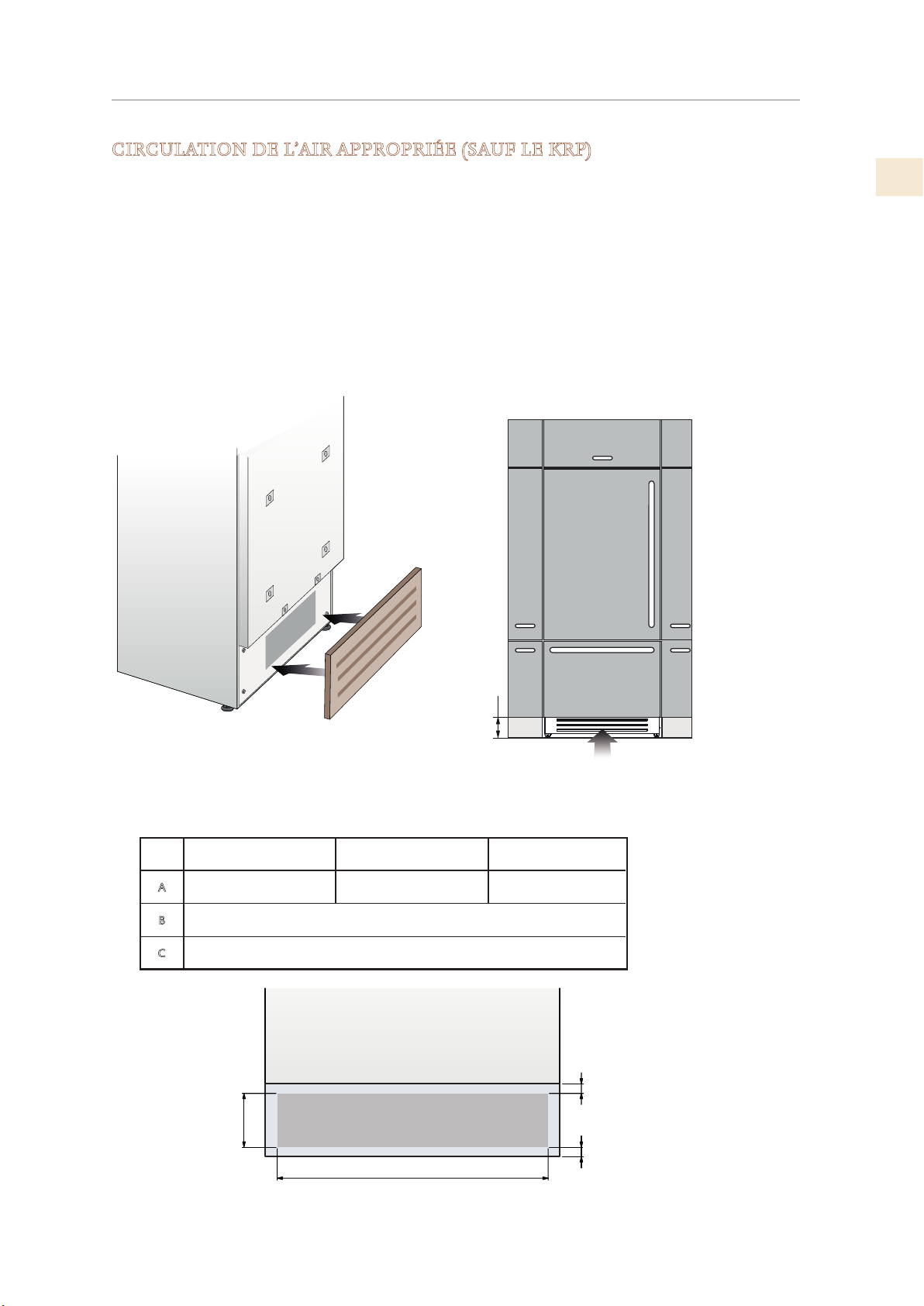
INSTALLATION FINALE
(SUITE)
CIRCULATION DE L’AIR APPROPRIÉE (SAUF LE KRP)
Un système à air forcé assure la ventilation à travers une grille située dans la
partie inférieure avant de l'appareil. Si la conception de la cuisine comprend une
toekick appliquée, celle-ci doit comporter de nombreuses ouvertures / fentes
pour maintenir un flux d’air adéquat, comme illustré ci-dessous. Les trous / fentes
peuvent être de n'importe quelle taille et forme, à condition que la surface totale
dégagée représente 50% de la taille totale de la couverture décorative. Dans ce
cas, pour garantir un flux d'air correct, il est recommandé de retirer la grille
frontale fournie avec l'appareil. La grille fournie est fixée à l'unité avec des
plaques magnétiques et peut être facilement retirée. Le couvercle doit être retiré
pour un nettoyage et une élimination réguliers de la poussière. Si un décoratif le
gril est utilisé, retirez le gril fourni pour permettre à l'air de circuler correctement.
FR
100 (4”)
Le graphique et l'illustration ci-dessous fournissent la quantité appropriée
de débit d'air nécessaire à la maintenance (Tous les modèles sauf KRP).
Modèles de 36 po
A
B
C
860 [33-7/8 po]
B
Modèles de 30 po
740 [29-1/8 po]
>100 [4 po]
10 [3/8 po]
A
Modèles de 24 po
560 [22 po]
C
C
© 2019 Hestan Commercial Corporation
34
Page 78
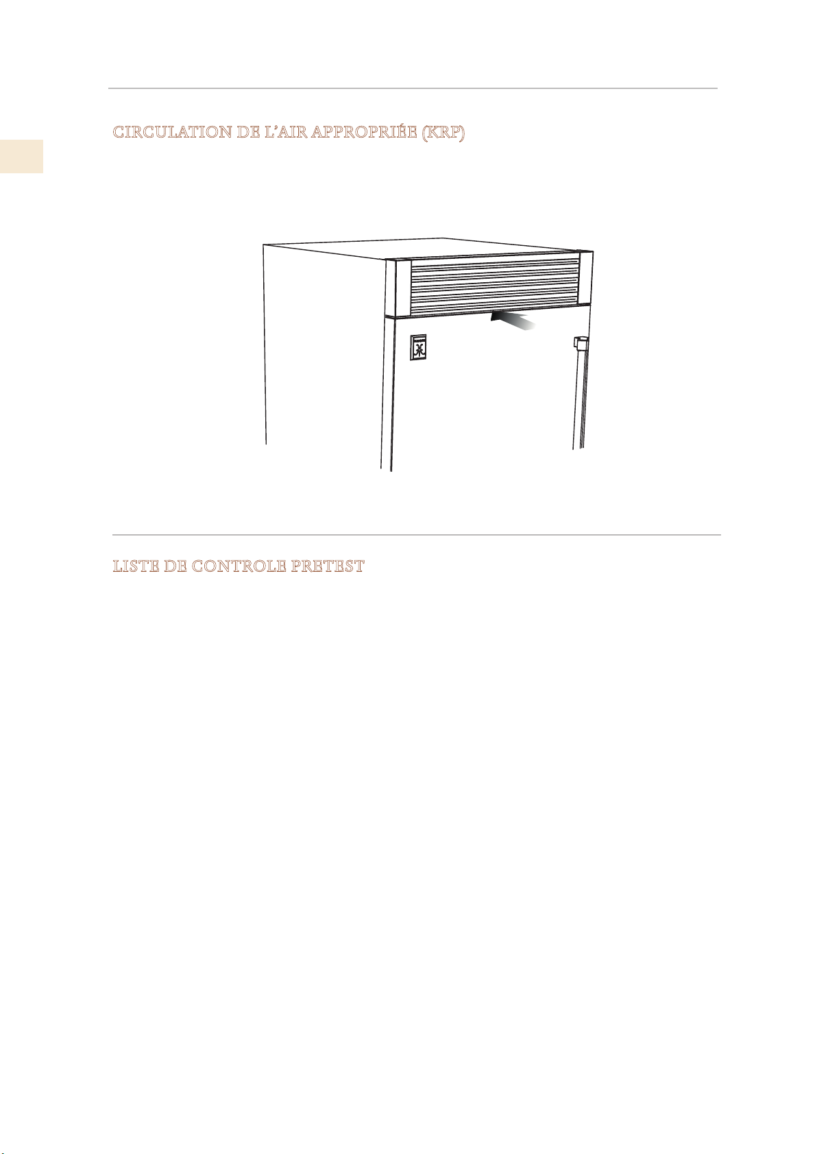
FR
INSTALLATION FINALE
CIRCULATION DE L’AIR APPROPRIÉE (KRP)
Pour les modèles KRP, la ventilation est assurée par un système à air forcé à travers une grille
située dans la partie supérieure du réfrigérateur. Cet espace ouvert dans le gril ne doit pas être
limité par un couvercle ou un dispositif susceptible de réduire le flux d’air, car cela réduirait
l’efficacité du produit et augmenterait la consommation d’énergie. Un évent doit être prévu à
l’arrière pour permettre à l’air de sortir. Voir page 5 pour l’emplacement et les dimensions.
(SUITE)
ESSAIS ET DÉMARRAGE INITIAL
LISTE DE CONTROLE PRETEST
; Vérifiez que le raccordement au système d’eau ne présente pas de fuite et que la vanne est
facilement accessible.
; Vérifiez que le raccordement électrique est correctement installé et que le disjoncteur est
identifié / marqué pour une utilisation ultérieure.
; Vérifiez que l’unité est à niveau et alignée avec les armoires adjacentes.
; Vérifiez que les supports anti-basculement sont sécurisés et que les connecteurs latéraux
sont sécurisés avec la garniture en place.
; Vérifiez que tous les rubans adhésifs et les emballages protecteurs temporaires internes ou
externes ont été retirés.
; Vérifiez la fermeture parfaite des portes et le coulissement en douceur des tiroirs et des
étagères.
; Si l’appareil est équipé d’une machine à glaçons, assurez-vous que la cartouche de filtre à
eau est installée. (Sauf si de l’eau filtrée est fournie à l’unité.)
35
© 2019 Hestan Commercial Corporation
Page 79
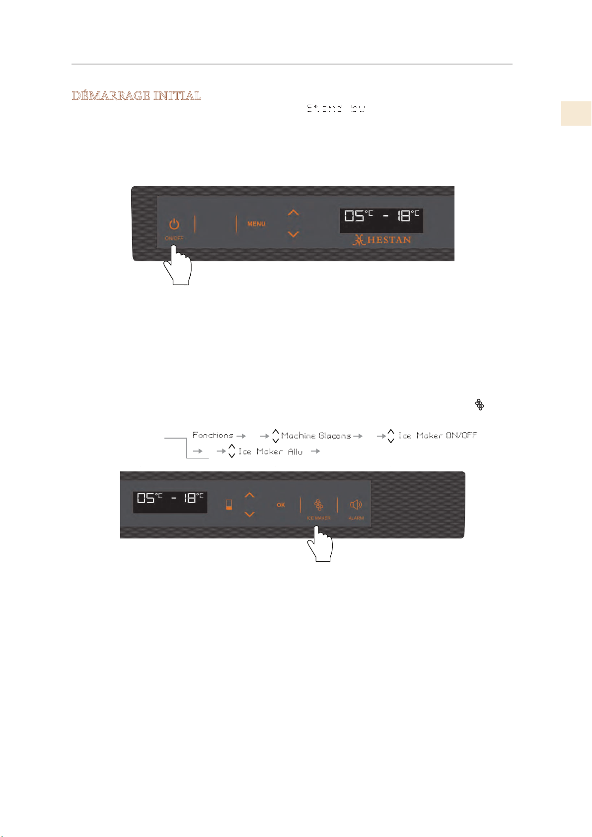
ESSAIS ET DÉMARRAGE INITIAL
Allumer la
(SUITE)
DÉMARRAGE INITIAL
Une fois l’appareil branché, l’écran devrait afficher .
Allumez l’appareil en appuyant sur le bouton d’alimentation pendant trois secondes. L’écran
affichera le message «Test initial» pendant environ 2 minutes. Après cette phase, les
compresseurs démarrent et restent allumés jusqu’à ce que la température préréglée en usine soit
atteinte. Laissez suffisamment de temps au réfrigérateur pour atteindre cette température avant
de charger des articles (6-12 heures).
Machine à glaçons
Si l’appareil est équipé d’une machine à glaçons:
1) Assurez-vous que la cartouche de filtre à eau est correctement installée
FR
2) Purgez l’air des conduites d’eau en activant la fonction «Nettoyage manuel» à partir des
options Menu-> Fonctions-> Filtre d’eau. Vous devrez peut-être exécuter cette séquence
plusieurs fois jusqu’à ce que vous cessiez d’écouter de l’air par le tube de remplissage de la
fabrique de glace.
3) Une fois la procédure terminée, allumez la machine à glaçons en touchant le bouton
(KRP, KRB) ou en utilisant le menu:
machine à glaçons
.
OK
OKOK
OK
Tiroir du bas
Les modèles KRP, KRB et KRW ont un tiroir inférieur qui opère par défaut en mode
congélateur. Le tiroir peut également être réglé sur d’autres modes de fonctionnement.
Consultez le manuel d’utilisation et d’entretien pour plus d’informations.
Préparation
Si, au début, le message de démarrage n’apparaît pas mais que d’autres informations
apparaissent à l’écran (telles que Réfrigérateur trop chaud, Congélateur trop chaud ou signaux
sonores audibles), le processus de refroidissement normal du réfrigérateur a commencé.
Si tel est le cas, désactivez tout signal sonore en appuyant sur le bouton Alarme, fermez la porte
et attendez que la température définie soit atteinte.
Il est nécessaire de laisser l’appareil atteindre la bonne température avant d’y placer des
aliments ou des boissons. (Prévoyez 6 à 12 heures.)
Pour plus d’informations sur le fonctionnement de l’appareil, reportez-vous au Manuel
d’utilisation et d’entretien.
© 2019 Hestan Commercial Corporation
36
Page 80

FR
LISTE DES PIÈCES
Visiter le site Web Hestan pour consulter la liste des pièces de ce produit:
www.hestanhome.com.
SERVICE
Toutes les réparations dans le cadre ou en dehors de la garantie doivent être effectuées par du
personnel d’entretien qualifié. Pour localiser un réparateur agréé dans la région, s’adresser au
concessionnaire Hestan, au représentant local ou à l’usine. Avant d’appeler, veiller à avoir les
numéros de modèle et de série à portée de la main.
Hestan Commercial Corporation
3375 E. La Palma Avenue
Anaheim, CA 92806
(888) 905-7463
GARANTIE LIMITÉE
ÉLÉMENTS COUVERTS PAR LA PRÉSENTE GARANTIE LIMITÉE:
Hestan Commercial Corporation (« HCC ») garantit à l’acheteur initial d’un produit de
refroidissement Hestan (le « Produit ») chez un revendeur agréé HCC que le Produit ne présente
aucun vice de matière ni de fabrication pendant une période de deux (2) ans à compter de la
date de l’achat initial au détail ou de la date de clôture en cas de construction neuve, suivant la
période la plus longue (« Période de garantie limitée »). HCC accepte de réparer ou de remplacer,
à sa seule discrétion, tout composant ou pièce du Produit dont la défaillance est due à des vices
de matières ou de fabrication pendant la Période de garantie limitée. La présente Garantie
limitée n’est pas transférable et n’est offerte à personne d’autre que l’acheteur initial au détail
(« Acheteur »). La présente garantie limitée n’est valable que pour les Produits achetés chez et
reçus d’un revendeur agréé HCC dans tous les Etats-Unis, dans le District de Columbia et au
Canada. La présente Garantie limitée ne s’applique qu’aux Produits pour usage non commercial,
à l’exclusion de ceux utilisés à des fins commerciales.
MARCHE À SUIVRE POUR UNE RÉPARATION AU TITRE DE LA GARANTIE:
En cas de défaillance du Produit pendant la Période de garantie limitée pour des raisons
couvertes par la présente Garantie limitée, l’Acheteur doit contacter immédiatement le
revendeur auquel il a acheté le Produit ou HCC au 888.905.7463.
Il incombe à l’Acheteur de rendre le Produit raisonnablement accessible pour réparation ou
de régler les frais de mise à disposition raisonnable du Produit pour réparation. La réparation
sera effectuée pendant les heures d’ouverture normales du Centre de réparation agréé par
Hestan. Dans la mesure où l’Acheteur demande une réparation en dehors des heures d’ouverture
normales du Centre de réparation agréé par Hestan, l’Acheteur règlera la différence entre le tarif
normal et celui des heures supplémentaires ou des primes. L’Acheteur doit régler tous les frais
de déplacement si celui-ci dépasse 80 km [50 milles] (dans un sens) par rapport au Centre de
réparation le plus proche agréé par Hestan.
ALLONGEMENTS AU-DELÀ DE LA PÉRIODE DE GARANTIE LIMITÉE D’UN AN:
En plus de la garantie limitée de deux ans, les composants qui suivent bénéficient d’un
prolongement de la garantie comme expressément énoncé ci-après:
Le compresseur, le condenseur, l’évaporateur, le séchoir et tous les tuyaux de raccordement
du produit (le cas échéant) sont garantis exempts de vices de matières et de fabrication dans
des conditions normales d’utilisation non-commerciale et de réparation pendant une période
de cinq (5) ans au profit de l’Acheteur initial. Cela exclut la corrosion superficielle, les rayures
et la décoloration susceptibles de se produire pendant une utilisation normale et se limite au
remplacement de la ou des pièces défectueuses, y compris ceux de main d’œuvre, de transport et
de manutention, le cas échéant.
37
© 2019 Hestan Commercial Corporation
Page 81

GARANTIE LIMITÉE
Le compresseur, le condenseur, l’évaporateur, le séchoir et tous les tuyaux de raccordement du
produit (le cas échéant) sont garantis exempts de vices de matières et de fabrication dans des
conditions normales d’utilisation non-commerciale et de réparation pendant une période de
douze (12) ans au profit de l’Acheteur initial. Cela exclut la corrosion superficielle, les rayures
et la décoloration susceptibles de se produire pendant une utilisation normale et se limite au
remplacement de la ou des pièces défectueuses, l’Acheteur assumant tous les autres coûts, y
compris ceux de main d’œuvre, de transport et de manutention, le cas échéant.
(SUITE)
ÉLÉMENTS NON-COUVERTS PAR LA PRÉSENTE GARANTIE LIMITÉE:
La présente Garantie limitée ne couvre pas ce qui suit, excluant toute responsabilité financière
de HCC: tous dommages ou vices affectant tout Produit non acheté chez un revendeur agréé
HCC; variations de coloris dans la finition ou autres dommages esthétiques; panne ou dommages
dus à une utilisation abusive ou erronée, un accident, un incendie, une catastrophe naturelle,
un usage commercial du Produit, une interruption de l’alimentation électrique ou en gaz du
Produit; dommages résultant d’une modification, d’une installation ou utilisation incorrecte du
Produit; dommages résultant de la réparation ou du remplacement incorrect ou sans autorisation
de tout composant ou pièce du Produit; dommages résultant d’un service après vente assuré
par quiconque autre qu’un agent ou représentant agréé du réseau commercial de Hestan; usure
normale et détérioration; dommages résultant de l’exposition du Produit à une atmosphère
corrosive contenant du chlore, du fluor ou toute autre substance chimique nuisible; dommages
résultant de l’absence d’un entretien normal du Produit; dommages dont HCC n’a pas été avisé
ou qui se sont produits après expiration de la Période de garantie limitée; dommages accessoires
et indirects causés par tout vice de matière ou de fabrication.
FR
ARBITRAGE:
La présente Garantie limitée est régie par la Loi fédérale sur l’arbitrage. Tout litige opposant
l’Acheteur à HCC et relatif au Produit ou à la présente Garantie limitée doit être résolu par voie
d’arbitrage exécutoire exclusivement sur une base individuelle avec l’Acheteur. L’arbitrage sera
effectué par l’Association Américaine d’Arbitrage (American Arbitration Association, « AAA
») conformément à ses règles d’arbitrage pour la protection du consommateur ou par JAMS.
L’audience d’arbitrage se tiendra devant un arbitre nommé par l’AAA ou par JAMS. L’arbitre ne
devra procéder à aucun arbitrage collectif et l’Acheteur devra renoncer à tout recours contre
HCC en qualité de représentant de tiers.
LIMITATION DE RESPONSABILITÉ:
La présente Garantie limitée constitue l’accord définitif, intégral et exclusif entre HCC et
l’Acheteur eu égard au Produit.
IL N’EXISTE AUCUNE GARANTIE EXPRESSE AUTRE QUE CELLES ÉNUMÉRÉES ET
DÉCRITES PLUS HAUT. AUCUNE GARANTIE EXPRESSE OU IMPLICITE, Y COMPRIS
SANS S’Y LIMITER, TOUTE GARANTIE IMPLICITE DE QUALITÉ MARCHANDE OU
D’ADAPTATION À UN USAGE PARTICULIER NE S’APPLIQUERA APRÈS L’EXPIRATION
DE LA PÉRIODE DE GARANTIE LIMITÉE INDIQUÉE PLUS HAUT. AUCUNE GARANTIE
EXPRESSE APPLICABLE À CE PRODUIT OFFERTE PAR UNE PERSONNE OU ENTREPRISE
QUELCONQUE N’ENGAGERA HCC. HCC NE GARANTIT EN AUCUNE FAÇON
L’ADAPTATION DU PRODUIT À UN USAGE PARTICULIER, SAUF DISPOSITION CONTRAIRE
DE LA LÉGISLATION APPLICABLE. HCC N’ASSUME AUCUNE RESPONSABILITÉ POUR
TOUT MANQUE À GAGNER, IMPOSSIBILITÉ DE RÉALISER DES ÉCONOMIES OU AUTRES
AVANTAGES NI POUR TOUT AUTRE DOMMAGE PARTICULIER, DIRECT OU INDIRECT
CAUSÉ PAR L’UTILISATION, L’USAGE ABUSIF OU L’INCAPACITÉ D’UTILISER CE PRODUIT,
QUELLE QUE SOIT LA THÉORIE JURIDIQUE SUR LAQUELLE LA DEMANDE SE FONDE,
MÊME SI HCC EST INFORMÉ DE LA POSSIBILITÉ DE TELS DOMMAGES. AUCUN
RECOUVREMENT À L’ENCONTRE DE HCC NE SERA SUPÉRIEUR AU PRIX D’ACHAT DU
PRODUIT. SANS LIMITER LA PORTÉE DE CE QUI PRÉCÈDE, VOUS ASSUMEZ TOUS LES
RISQUES ET LA RESPONSABILITÉ DES PERTES, DOMMAGES OU BLESSURES ET DÉGÂTS
MATÉRIELS SUBIS PAR VOUS-MÊMES ET DES TIERS RÉSULTANT DE L’UTILISATION,
DE L’USAGE ABUSIF OU DE L’INCAPACITÉ D’UTILISER CE PRODUIT, QUI NE SONT PAS
© 2019 Hestan Commercial Corporation
38
Page 82

FR
GARANTIE LIMITÉE
CAUSÉS DIRECTEMENT PAR LA NÉGLIGENCE DE HCC. LA PRÉSENTE GARANTIE LIMITÉE
FORMULE VOTRE RECOURS EXCLUSIF.
Aucune déclaration ni aucun engagement verbal ou écrit de la part de qui que ce soit, y compris
sans s’y limiter un employé, représentant ou agent de HCC, ne créera une garantie ni élargira en
quoi que ce soit la portée de la présente Garantie limitée expresse d’un an. En cas de divergence
entre la présente garantie limitée et tout autre accord ou déclaration lié ou relatif au Produit, ce
sera cette Garantie qui s’applique. Si une disposition quelconque de la présente Garantie limitée
est déclarée invalide ou inapplicable, elle sera réputée modifiée dans la limite nécessaire pour la
rendre applicable et le reste de la Garantie limitée restera valide et applicable selon ses modalités.
(SUITE)
INTERACTION ENTRE CERTAINES LOIS ET LA PRÉSENTE GARANTIE LIMITÉE:
Il se peut que certains États, Provinces et Territoires n’autorisent pas la limitation de durée
d’une garantie implicite ni l’exclusion ou la restriction des dommages directs ou indirects. Les
limitations ou exclusions qui précèdent peuvent par conséquent ne pas être applicables. Il se
peut que certains États, Provinces ou Territoires prévoient d’autres droits et recours en matière
de garantie. Les dispositions de la présente Garantie limitée n’ont pas pour but de limiter,
modifier, restreindre, nier ni exclure les conditions obligatoires de garantie prévues par des États,
Provinces ou Territoires, y compris certaines garanties implicites. La présente garantie confère
des droits précis, auxquels peuvent s’en ajouter d’autres qui varient selon le lieu.
Toute question relative à la présente Garantie limitée peut être adressée à:
Hestan Commercial Corporation au (888) 905-7463
39
© 2019 Hestan Commercial Corporation
Page 83

FR
© 2019 Hestan Commercial Corporation
40
Page 84

RETAIN THIS MANUAL FOR FUTURE REFERENCE
CONSERVEZ CE MANUEL POUR UNE RÉFÉRENCE FUTURE
Hestan Commercial Corporation
3375 E. La Palma Ave.
Anaheim, CA 92806
(888) 905-7463
©2019 Hestan Commercial Corporation P/N 020056 REV B
 Loading...