


www.hesaitech.com
1902A1
64-Channel Short-Range
PandarQT
Mechanical LiDAR
Q01-en-
User Manual
HESAI WeChat
Safety Notice
PLEASE READ AND FOLLOW ALL INSTRUCTIONS CAREFULLY AND CONSULT ALL RELEVANT NATIONAL AND INTERNATIONAL SAFETY REGULATIONS
FOR YOUR APPLICATION.
Caution
To avoid violating the warranty and to minimize the chances of getting electrically shocked, please do not disassemble the device on your own accord. The
device must not be tampered with and must not be changed in any way. There are no user-serviceable parts inside the device. For repairs and
maintenance inquiries, please contact an authorized Hesai Technology service provider.
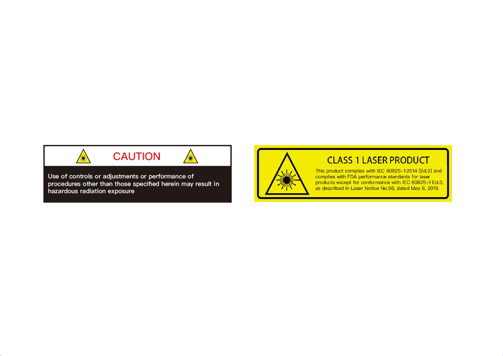
Laser Safety Notice – Laser Class 1
This device satisfies the requirements of
• IEC 60825-1:2014
• 21 CFR 1040.10 and 1040.11 except for conformance with IEC 60825-1 Ed.3, as described in Laser Notice No.56, dated May 8, 2019
NEVER LOOK INTO THE TRANSMITTING LASER THROUGH A MAGNIFYING DEVICE (MICROSCOPE, EYE LOUPE, MAGNIFYING GLASS, ETC.)

Safety Precautions
In all circumstances, if you suspect that the device malfunctions or is
damaged, stop using it immediately to avoid potential hazards and injuries.
Contact an authorized Hesai Technology service provider for more
information on device disposal.
Handling
This device contains metal, glass, plastic, as well as sensitive electronic
components. Improper handling such as dropping, burning, piercing, and
squeezing may cause damage to the device.
Enclosure
This device contains high-speed rotating parts. To avoid potential injuries,
DO NOT operate the device if the enclosure is loose or damaged.
Repair
DO NOT open and repair the device without direct guidance from Hesai
Technology. Disassembling the LiDAR may cause degraded performance,
failure in water resistance, or potential injuries to the operator.
Power Supply
Use only the cables and power adapters provided by Hesai Technology.
Only the power adapters that meet the device’s power requirements and
the applicable safety standards can be used. Using damaged
cables/adapters or supplying power in a humid environment can result in
fire, electric shock, personal injuries, product damage, or property loss.
Prolonged Exposure to Hot Surface
Prolonged exposure to the device’s hot surface may cause discomfort or
injury. If the device has been powered and operating for a long time, avoid
skin contact with the device or its power adapter.
Vibration
Strong vibration may cause damage to the device and should be avoided.
Radio Frequency Interference
Please observe the signs and notices on the device that prohibit or restrict
the use of electronic devices. Although the device is designed, tested, and
manufactured to comply with the regulations on RF radiation, the radiation
from the device may still influence other electronic devices.
Medical Device Interference
Some components in the device can emit electromagnetic fields, which
may interfere with medical devices such as cochlear implants, heart
pacemakers and defibrillators. Consult your physician and medical device
manufacturers for specific information regarding your medical device and
whether you need to keep a safe distance from the LiDAR. If you suspect
that the LiDAR is interfering with your medical device, stop using the LiDAR
immediately.
Explosive Atmosphere and Other Air Conditions
Do not use the device in any area where potentially explosive atmospheres
are present, such as high concentrations of flammable chemicals, vapors or
particulates (including particles, dust, and metal powder) in the air.
Exposing the device to high concentrations of industrial chemicals,
including liquefied gases that are easily vaporized (such as helium), can
damage or weaken the device’s function. Please observe all the signs and
instructions on the device.
Light Interference
Some precision optical instruments may be interfered by the laser light
emitted from the device.
Eye Safety
Although the device meets Class 1 eye safety standards, operators should
still avoid looking directly at the LiDAR for maximum self-protection.

Contents
1 Introduction ............................................................................................................ 1
1.1 Operating Principle ................................................................................................. 1
1.2 LiDAR Structure ........................................................................................................ 2
1.3 Channel Distribution ............................................................................................... 3
1.4 Specifications ............................................................................................................ 4
2 Setup ......................................................................................................................... 5
2.1 Mechanical Installation ........................................................................................... 5
2.2 Interfaces .................................................................................................................... 7
2.3 Connecting Box (Optional) ................................................................................... 9
2.4 Use ............................................................................................................................. 12
3 Data Structure ...................................................................................................... 13
3.1 Point Cloud Data Packet ...................................................................................... 14
3.2 GPS Data Packet ..................................................................................................... 18
4 Web Control ......................................................................................................... 23
4.1 Homepage ............................................................................................................... 23
4.2 Settings ..................................................................................................................... 24
4.3 Angle Range ............................................................................................................ 25
4.4 Device Info ............................................................................................................... 27
4.5 Time Statistics ......................................................................................................... 28
4.6 Firmware Upgrade ................................................................................................. 29
6 Sensor Maintenance ........................................................................................... 37
7 Troubleshooting .................................................................................................. 38
Appendix I PTP Protocol ....................................................................................... 40
Appendix II FCC Statement .................................................................................. 42
Appendix III Support and Contact ..................................................................... 43
5 PandarView ........................................................................................................... 30
5.1 Installation ................................................................................................................ 30
5.2 Use ............................................................................................................................. 31
5.3 Features .................................................................................................................... 33
1 Introduction
This manual describes the specifications, installation, and data output format of PandarQT, a 64-channel mechanical LiDAR.
This manual is under constant revision. Please contact Hesai for the latest version.
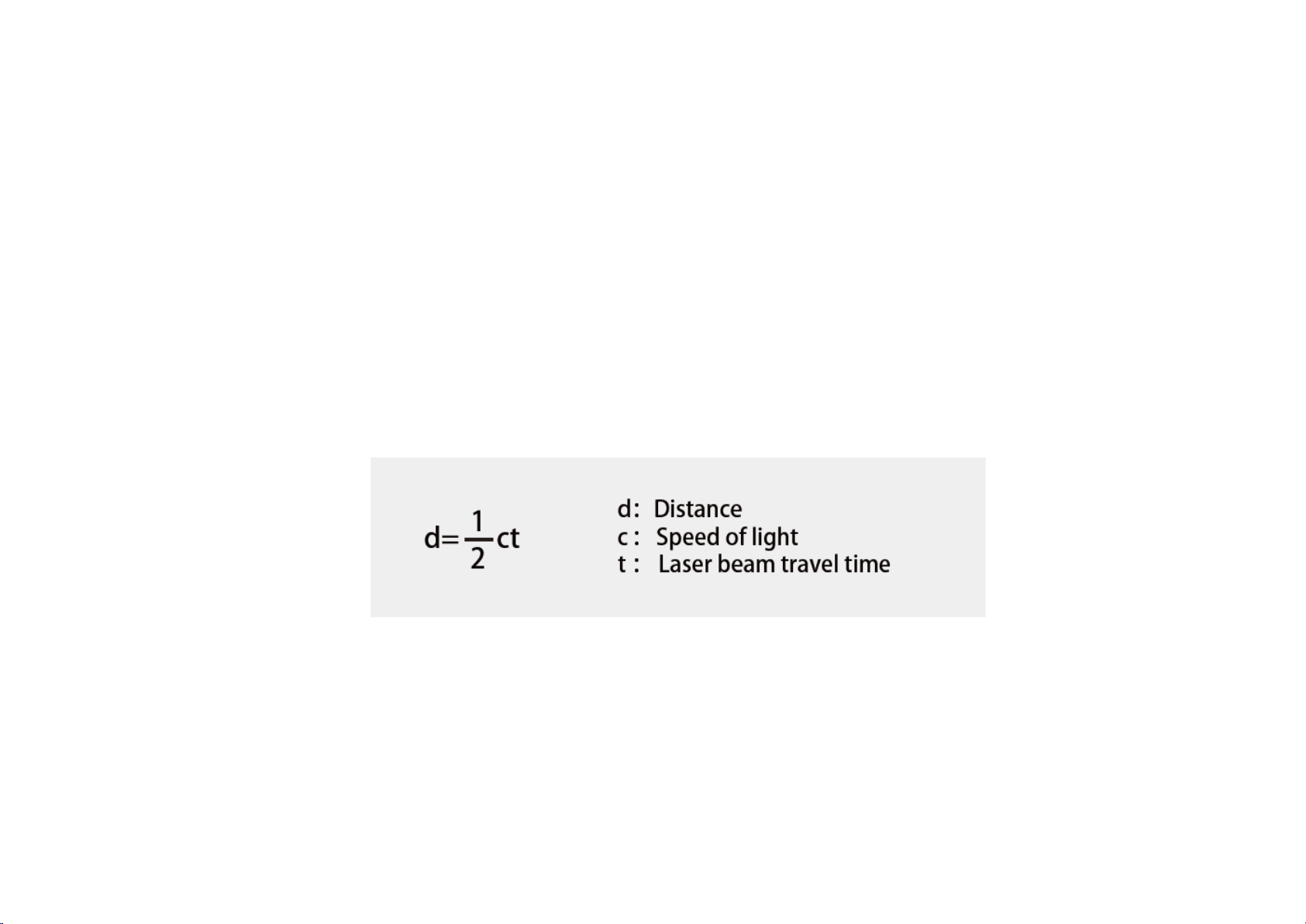
1.1 Operating Principle
Distance Measurement: Time of Flight (ToF)
1) A laser diode emits a beam of ultrashort laser pulses onto the object.
2) Diffuse reflection of the laser occurs upon contact with the target object. The beams are detected by the optical sensor.
3) Distance to object can be accurately measured by calculating the time between emission and receipt by the sensor.
Figure 1.1 ToF Formula
1
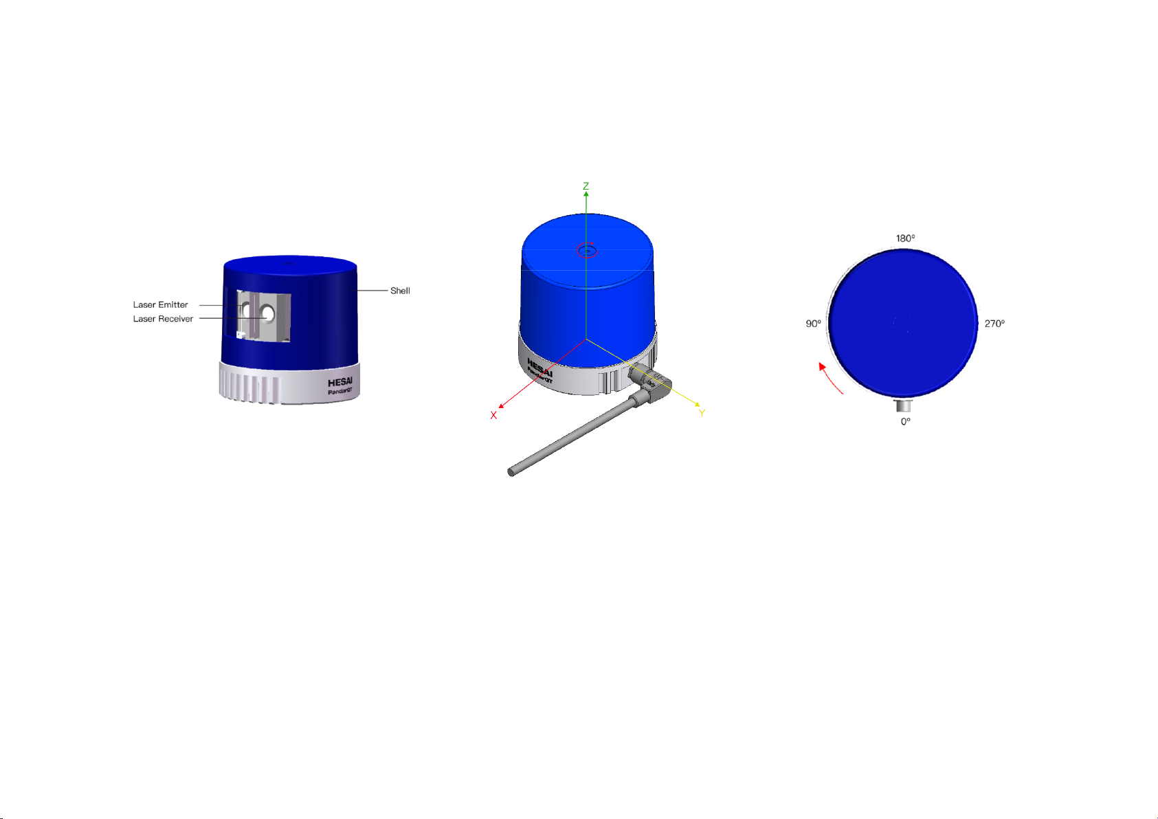
1.2 LiDAR Structure
64 pairs of laser emitters and receivers are attached to a motor that rotates horizontally.
Figure 1.2 Partial Cross-Sectional Diagram Figure 1.3 Coordinate System (Isometric View) Figure 1.4 Rotation Direction (Top View)
The LiDAR’s coordinate system is shown above. The Z-axis is the axis of rotation.
The origin is shown as a red dot in Figure 1.6 on the next page. After geometric transform, all the measurements are relative to the origin.
Each laser channel has an intrinsic horizontal angle offset. When Channel 18 passes the zero degree position illustrated in Figure 1.4, the azimuth data in
the corresponding UDP data block will be 0°.
2

1.3 Channel Distribution
The vertical resolution is unevenly distributed across all channels.
Figure 1.5 Channel Vertical Distribution Figure 1.6 Laser Firing Position
3

1.4 Specifications
SENSOR
MECHANICAL/ELECTRICAL/OPERATIONAL
Scanning Method
Mechanical Rotation
Laser Class
Class 1 Eye Safe
Channel
64 Waterproof Grade
IPX7
Range
0.1 to 20 m (at 10% reflectivity)
Weight
0.4 kg
±5 cm (0.1 to 0.5 m)
FOV (Horizontal)
360°
Operating Voltage
9~65 VDC
Resolution (Horizontal)
0.6°
Power Consumption
7 W
FOV (Vertical)
104.6° (-52.3° to +52.3°)
Operating Temperature
-20℃ to 65℃
Resolution (Vertical)
Finest at 1.4°
Frame Rate
10 Hz
DATA I/O
Returns
Single/Dual
Data Transmission
UDP/IP Ethernet (100BASE-T1 Slave Mode)
Distance, Azimuth Angle, Background
Single Return Mode: 384,000 pts/s
Clock Source
GPS / PTP
PTP Clock Accuracy
≤1 μs
PTP Clock Drift
≤1 μs/s
Range Accuracy
±2.5 cm (0.5 to 15 m)
Dimensions
±10 cm (15 to 30 m)
Data Outputs
Data Points Generated
NOTE Specifications are subject to change without notice.
NOTE Range accuracy as the average range error across all channels may vary with range, temperature and target reflectivity.
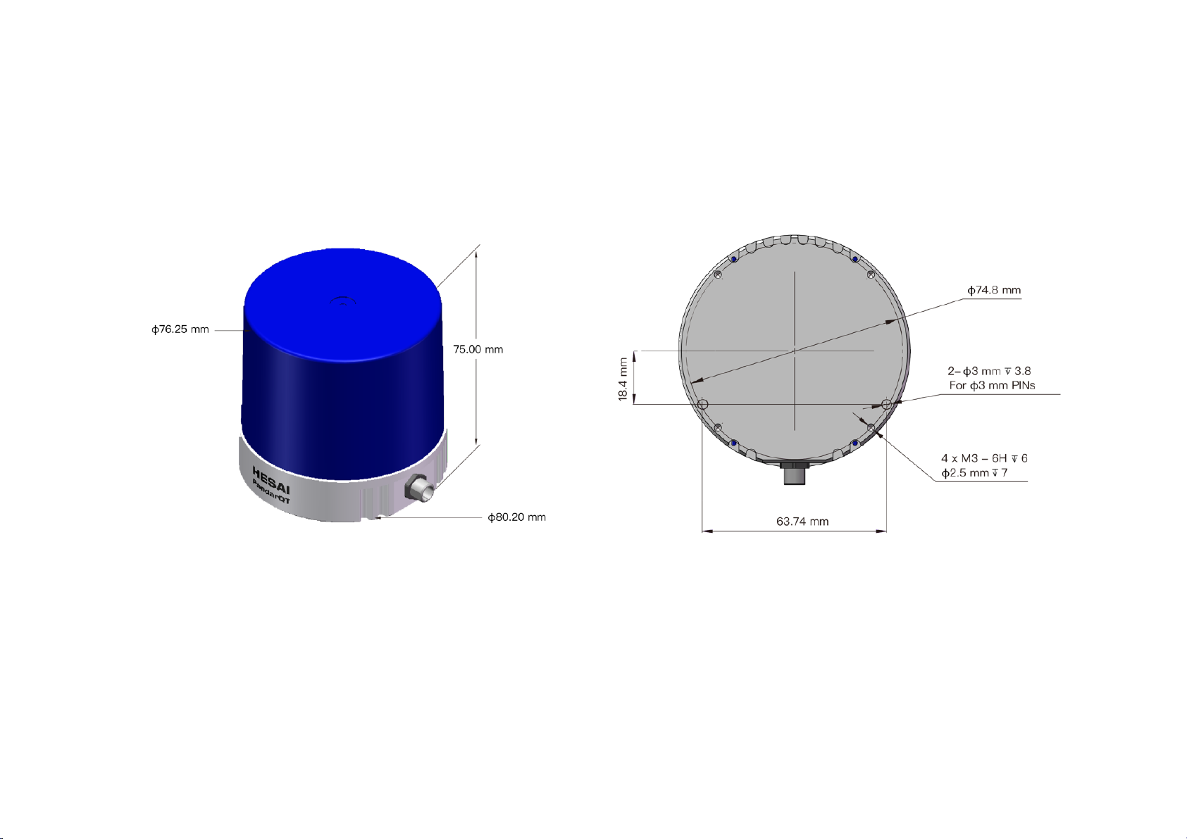
Height: 75.0 mm
Diameter: 80.2 mm
Illumination
Dual Return Mode: 768,000 pts/s
4
2 Setup
2.1 Mechanical Installation
Figure 2.1 Isometric View Figure 2.2 Mounting Base
5
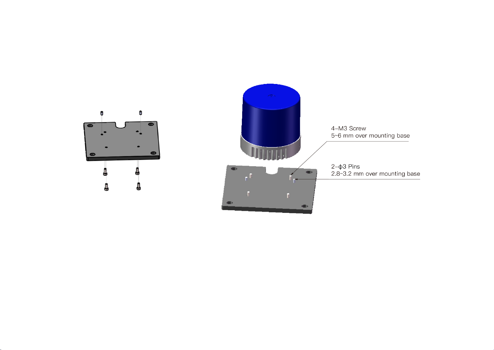
Installation
Figure 2.3 Installation Diagram
6
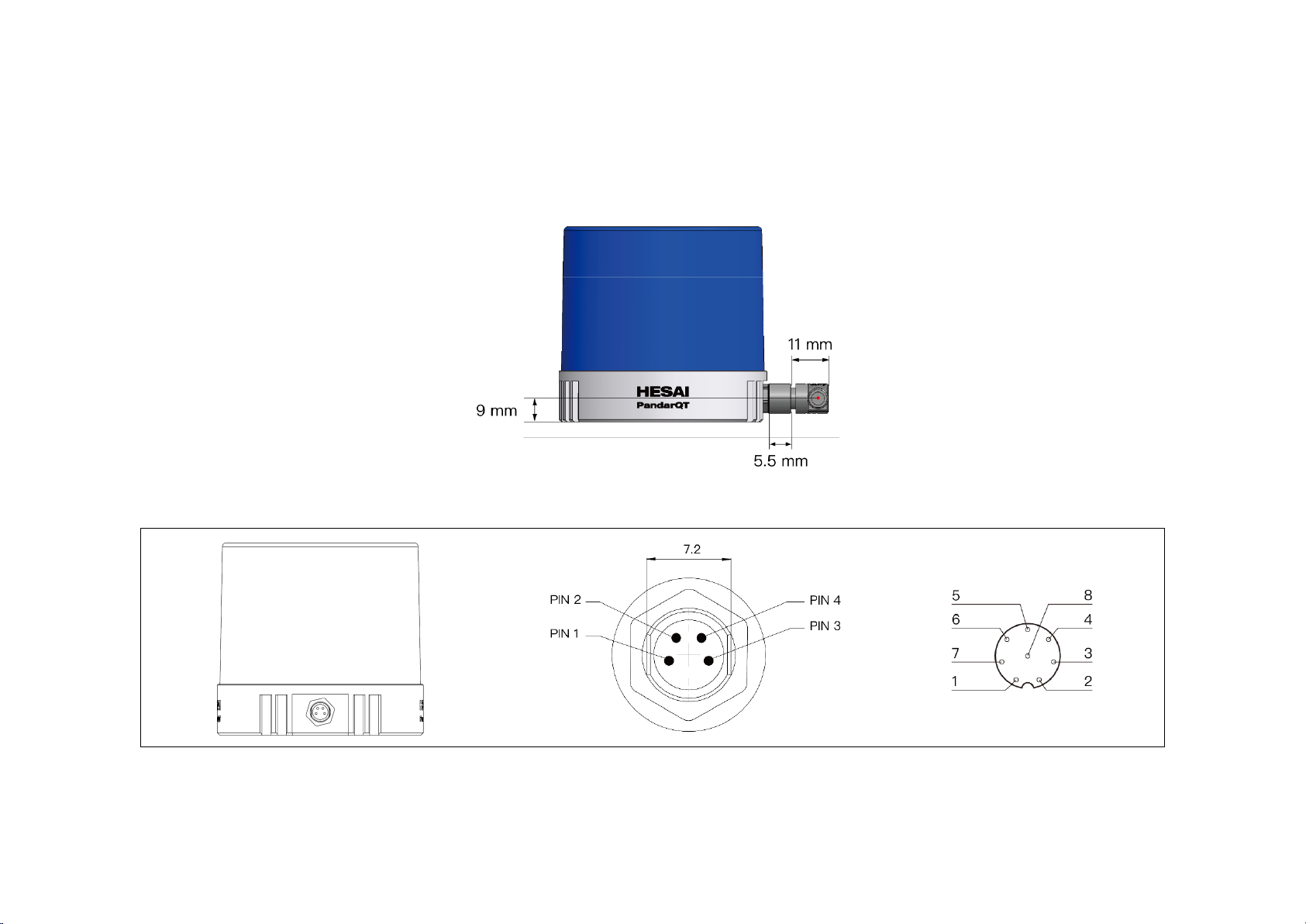
2.2 Interfaces
PandarQT by default uses a 4-pin M8 male socket (with needles inside), which includes power wires and 100BASE-T1 twist-pairs. Another option is an 8-
pin male socket with the same size. The use of 4-pin M8 sockets is strongly recommended.
Figure 2.4 Connector Dimensions
Connector 4-pin 8-pin
Figure 2.5 PandarQT Connector Options (Male socket, on the LiDAR)
7
The 4-pin male socket (recommended):
4
GPS_RX
Pin # Description
1 VIN
2 GND
3 Ethernet_TRX+
4 Ethernet_TRX-
The 8-pin male socket (optional, not recommended):
Pin # Description
1 VIN
2 Ethernet_TRX-
3 Ethernet_TRX+
5 GPS_PPS
6 Sync_N
7 Sync_P
8 GND
Cables
The optional cable for connecting QT to the connection box is 2 m in length.
Contact Hesai if you need customized cables for connecting the LiDARs to your control units directly. The maximum allowable diameter of power wires is
0.511 mm, 24 AWG.
When choosing cables, please check their voltage drop and power consumption to ensure a minimum of 9 V DC input to the LiDARs.
TYPE
Diameter
(mm)
Resistance/meter
(Ohm)
Max Voltage Drop
over 1 m cable (V)
Max Voltage Drop
over 6 m cable (V)
Average Power Consumption
over 1 m cable (W)
Average Power Consumption
over 6 m cable (W)
24AWG 0.511 0.0894 0.1788 1.0728 0.064368 0.386208
8
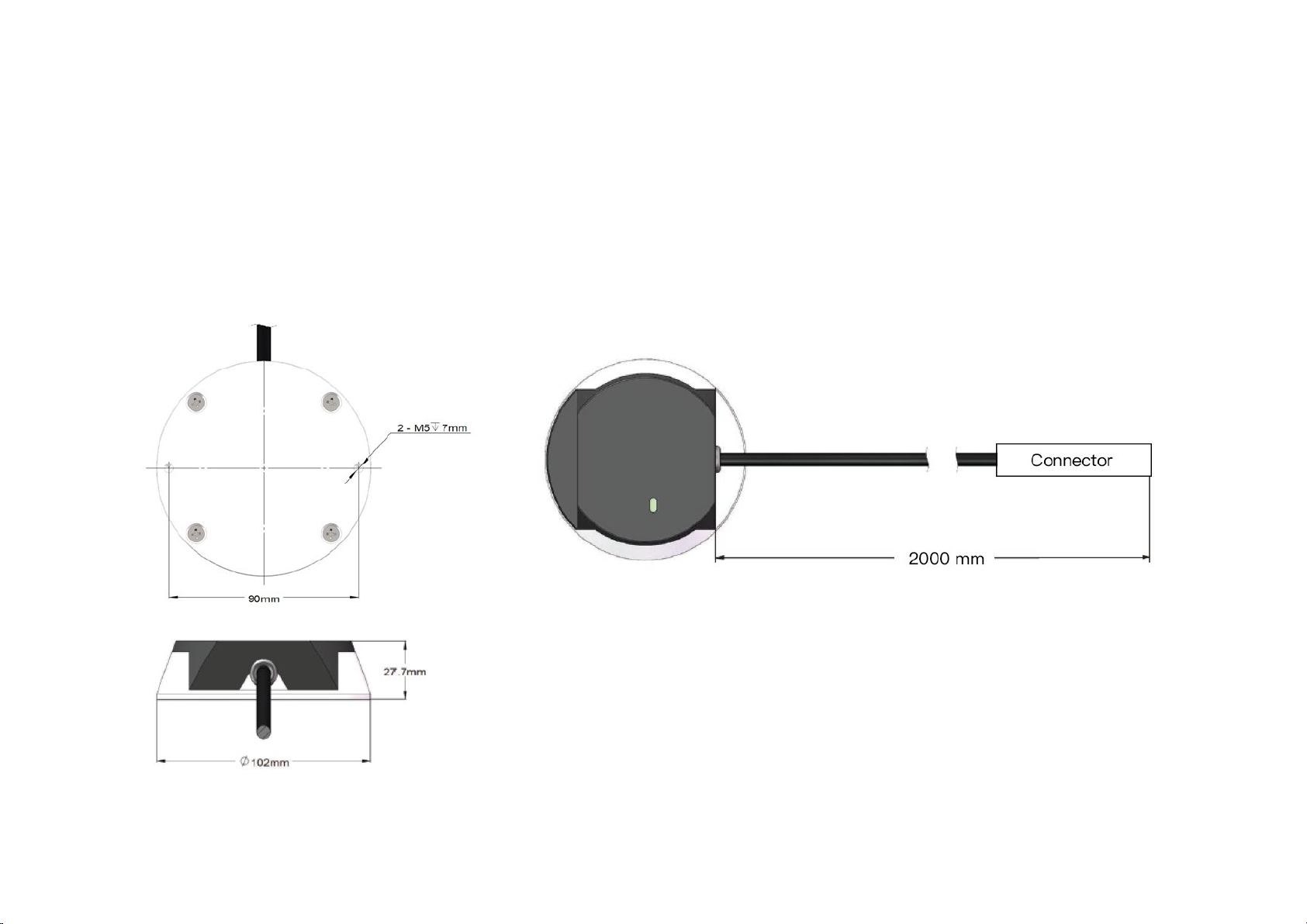
2.3 Connecting Box (Optional)
This device converts automotive 100BASE-T1 to 100BASE-TX typical Ethernet, as well as providing a power port with 5.5 mm X 2.1 mm socket and a GPS
port.
Users may connect the LiDAR directly or use the connecting box.
The cable length from the connector to the connecting box is 2 m by default.
NOTE The GPS port only supports 8-pin cables.
Figure 2.6 Connecting Box
9
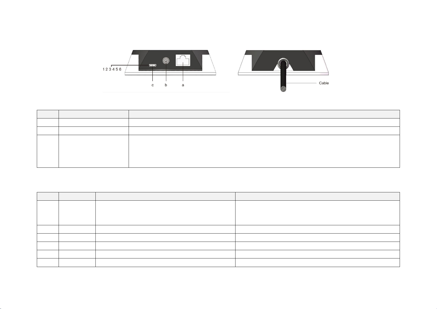
2.3.1 Connecting Box Interfaces
Port #
Port Name
Description
3
Output
Ground for the external GPS module
-
Table 2.2 Connecting Box Interfaces
a
b Power Port DC power adapter with voltage ranging from 12 V to 48 VDC and a minimum power output of 18 W is suggested
c GPS Port Connector type: JST SM06B-SRSS-TB
The GPS port pin numbers are 1 to 6 from left to right, defined as follows:
Pin # Direction Pin Description Requirements
1 Input PPS (pulse-per-second) signal for synchronization TTL level 3.3 V/5 V
2 Output Power for the external GPS module 5 V
4 Input Receiving serial data from the external GPS module RS232 level
5 Output Ground for the external GPS module -
6 Output Transmitting serial data to the external GPS module RS232 level
Standard Ethernet Port
RJ45, 100BASE-TX Ethernet
Recommended connector for the external GPS module: JST SHR-06V-S-B
Voltage standard: RS232
Baud rate: 9600 bps
Table 2.3 GPS Pin Description
Pulse width: 1 ms or longer is recommended
Cycle: 1 s (from rising edge to rising edge)
10
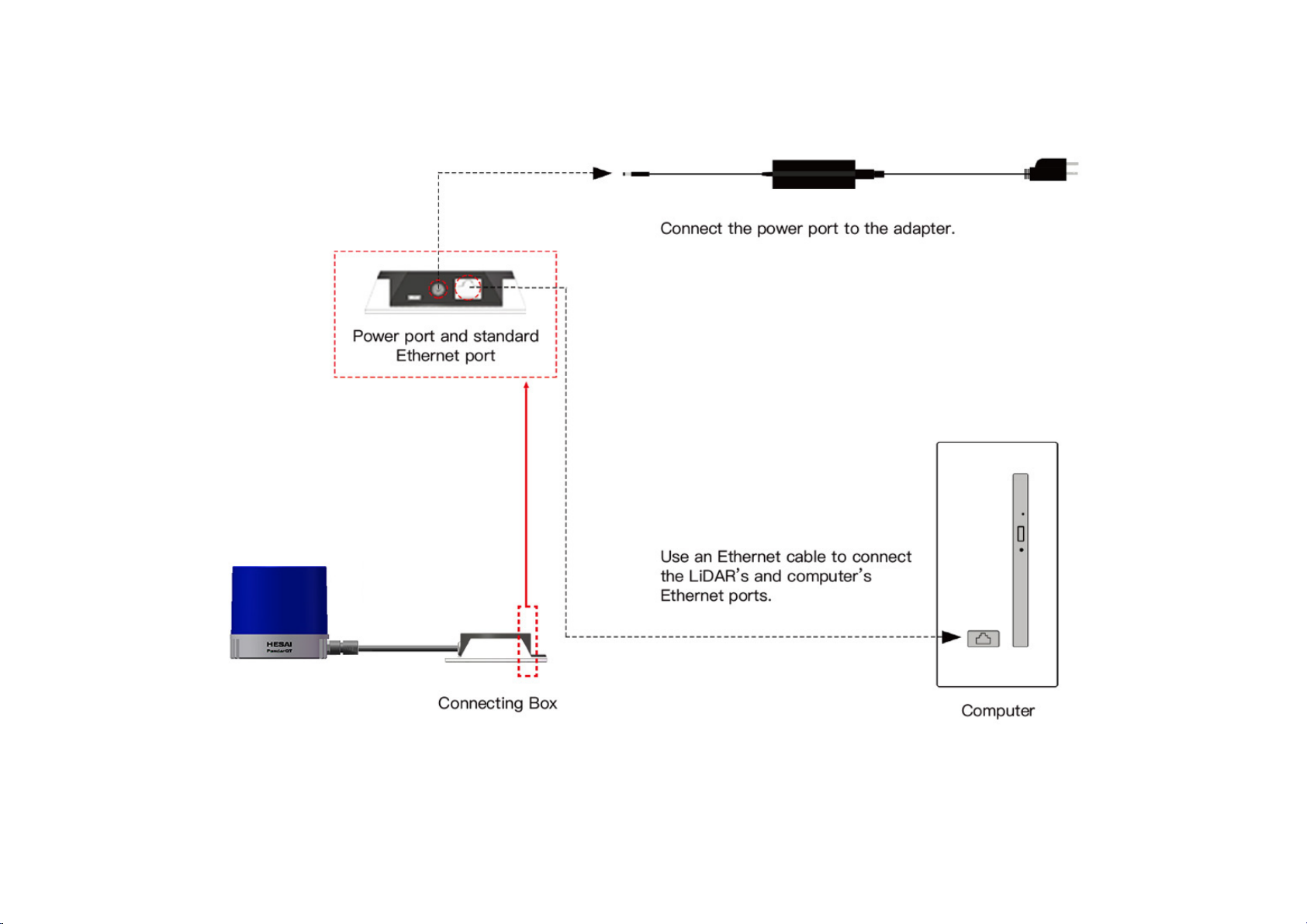
2.3.2 Connection
Figure 2.7 LiDAR Connection When Using the Connecting Box
NOTE Refer to Appendix I when PTP protocol is used.
11

2.4 Use
The Pandar family LiDARs do not have a power switch. They start operating once wired and powered up.
• To receive data on your PC, set the PC’s IP address to 192.168.1.100 and subnet mask to 255.255.255.0
For Ubuntu-16.04: For Windows:
Use the ifconfig command in the terminal:
~$ sudo ifconfig enp0s20f0u2 192.168.1.100
(replace enp0s20f0u2 with the local network port name)
• To record and display point cloud data, see Chapter 5 PandarView
• To set parameters, check device info, and upgrade firmware, see Chapter 4 Web Control
• The SDK (Software Development Kits) download links can be found at www.hesaitech.com/en/download
1) Open the Network Sharing Center, click on “Ethernet”
2) In the “Ethernet Status” interface, click on “Properties”
3) Double-click on “Internet Protocol Version 4 (TCP/IPv4)”
4) Configure the IP address to 192.168.1.100 and subnet mask to 255.255.255.0
12

3 Data Structure
Fast Ethernet UDP/IP is used for data output. The output data includes Point Cloud Data Packets and GPS Data Packets. Each data packet consists of an
Ethernet header and UDP data.
Figure 3.1 Data Structure with UDP Sequence OFF
The UDP sequence feature is OFF by default. When UDP sequence is ON, the Tail in the UDP data changes from 22 bytes to 26 bytes.
13

3.1 Point Cloud Data Packet
3.1.1 Ethernet Header
Each LiDAR has a unique MAC address.
The source IP is 192.168.1.201 by default. The destination IP address is 0xFF FF FF FF and in broadcast form.
Ethernet Header: 42 bytes
Ethernet II MAC 12 bytes Destination: broadcast (0xFF: 0xFF: 0xFF: 0xFF: 0xFF: 0xFF)
Source: (xx:xx:xx:xx:xx:xx)
Ethernet Data Packet Type 2 bytes 0x08, 0x00
Internet Protocol 20 bytes Shown in Figure 3.2
UDP Port Number 4 bytes UDP source port (0x2710, representing 10000)
Destination port (0x0940, representing 2368)
UDP Length 2 bytes 0x04b2 when UDP sequence is OFF, representing 1202 bytes (8 bytes more than the size of the Point Cloud
UDP Data, shown in Figure 3.1)
0x04b6 when UDP sequence is ON, representing 1206 bytes
UDP Checksum 2 bytes -
Table 3.1 Point Cloud Data Packet – Ethernet Header
Figure 3.2 Point Cloud Ethernet Header – Internet Protocol
14

3.1.2 UDP Data
Header: 8 bytes
Body: 1164 bytes (6 blocks)
Block 1
Block 2
Block 3
…
Block 6
All the multi-byte values are unsigned and in little endian format.
Header
0xEEFF 2 bytes SOP (start of packet), 0xEE first
Laser N 1 byte 0x40 (64 channels)
Block N 1 byte 0x6 (6 blocks per packet)
Reserved 1 byte -
Dis Unit 1 byte 4 mm
Reserved 1 byte -
Reserved 1 byte -
Table 3.4 Point Could UDP Data – Header
Body
Azimuth 1 Azimuth 2 Azimuth 3 … Azimuth 6
Channel 1 Channel 1 Channel 1 … Channel 1
Channel 2 Channel 2 Channel 2 … Channel 1
… … … … …
Channel 64 Channel 64 Channel 64 … Channel 64
Table 3.5 Point Could UDP Data – Body
Block size = 64 * Size of Channel XX + Size of Azimuth
NOTE Under the Dual Return mode, the ranging data from each firing is stored in two adjacent blocks: the odd number block is the last return, and the
even number block is the strongest return. If the last and strongest returns coincide, the second strongest return will be placed in the even number block.
The azimuth changes every two blocks.
15

Each Block in the Body: 194 bytes
Azimuth
2 bytes
Current reference angle of the rotor
Azimuth[15:0]: lower byte Azimuth_L[7:0], upper byte Azimuth_H[15:8].
Azimuth Angle = [Azimuth_H, Azimuth_L] / 100° = Azimuth / 100°
Channel XX 3 bytes 2-byte distance data Distance[15:0]: lower byte Distance_L[7:0], upper byte Distance_H[15:8]
Distance Value = [Distance_H, Distance_L] * 4 mm = Distance * 4
Maximum Distance Value = (2 ^ 16 – 1) * 4 mm = 262.14 m
1-byte background
illumination data
Relative brightness of the receiving FOV
Synchronized to the point cloud, but not related to the emitting laser pulse or distance
Table 3.6 Point Cloud UDP Data – Block Definition
Tail
Tail: 22 (+4) bytes
Reserved 5 bytes -
0x01 for high temperature; 0x00 for normal operation
High Temperature Shutdown
Flag
1 byte
When high temperature is detected, the shutdown flag will be set to 0x01, and the system will shut down
after 60 s. The flag remains 0x01 during the 60 s and the shutdown period
When the system is no longer in high temperature status, the shutdown flag will be reset to 0x00 and the
system will automatically return to normal operation
Reserved 2 bytes -
Motor Speed 2 bytes speed_2_bytes [15:0] = speed (RPM)
GPS Timestamp 4 bytes Packing time of this data packet, in units of 1 μs
Range: 0 to 1000000 μs (1 s)
Return Mode Information 1 byte 0x37 for Strongest Return mode, 0x38 for Last Return mode, and 0x39 for Dual Return mode
Factory Information 1 byte 0x42 (or 0x43)
UTC 6 bytes Year, month, date, hour, minute, second, decimal digit
UDP Sequence 4 bytes
Added only when UDP sequence is ON
Label the sequence number of Point Cloud UDP packets, 1 to 0xFF FF FF FF in little endian format
Table 3.7 Point Cloud Data UDP Data – Tail
16

Example of UDP Data Analysis
Take PandarQT’s Channel 5 in Block 3 of the UDP Data as an example:
1) Vertical angle of Channel 5 is 43.877°, according to the calibration file included with each LiDAR.
1. Horizontal angle is the current reference angle of the rotor (Azimuth of Block 3) plus the horizontal angle offset (7.388°, according to the calibration file
included with each LiDAR). Define clockwise in the top view as the horizontal angles’ positive direction
2. The 2-byte distance data in the UDP Data Packet, multiplied by 4 mm, is the actual distance in real world millimeters.
After determining the horizontal angle, vertical angle, and distance of a data point, this point can be drawn in a polar or rectangular coordinate system. The
real-time point cloud data is drawn by analyzing every point in the UDP data.
17

3.2 GPS Data Packet
GPS Data Packets are triggered every second. All the multi-byte values are unsigned and in little endian format.
Before $GPRMC messages are available from the external GPS module
Each rising edge of the LiDAR’s internal 1 Hz signal triggers a GPS Data Packet.
The time and date in the GPS Data Packets are unreal, starting from 00 01 01 00 00 00 (year, month, day, hour, minute, second) and increasing with the
internal 1 Hz signal.
Once the LiDAR receives the PPS (pulse-per-second) signal and $GPRMC messages
The internal 1 Hz signal will be locked to the PPS. Each rising edge still triggers a GPS Data Packet.
Meanwhile, the LiDAR will extract the actual UTC time and date from $GPRMC messages, and stamp them into both Point Cloud Data Packets and GPS
Data Packets.
• Point Cloud Data Packets: 6-byte UTC Time (year, month, day, hour, minute, second) in decimal
• GPS Data Packets: 6-byte Date (year, month, day) and 6-byte Time (second, minute, hour) in ASCII
The GPS module sends first the PPS signal and then the $GPRMC message. At the rising edge of the PPS pulse, the corresponding $GPRMC message is not
yet available. Therefore, the LiDAR extracts UTC information from the previous $GPRMC message and automatically adds 1 full second. Users need not
worry.
When GPS signal is lost
The LiDAR will still trigger GPS Data Packets by the rising edge of the internal 1 Hz signal. However, the GPS time in the packets will be counted by the
internal 1 Hz signal and will drift from the actual GPS time.
3.2.1 Ethernet Header
The source IP is 192.168.1.201 by default. The destination IP address is 0xFF FF FF FF and in broadcast form.
18

Table 3.5 GPS Data Packet – Ethernet Header
Ethernet Header: 42 bytes
Ethernet II MAC 12 bytes Destination: broadcast (0xFF: 0xFF: 0xFF: 0xFF: 0xFF: 0xFF)
Source: (xx:xx:xx:xx:xx:xx)
Ethernet Data Packet Type 2 bytes 0x08, 0x00
Internet Protocol 20 bytes Shown in the figure below
UDP Port Number 4 bytes UDP source port (0x2710, represents 10000)
Destination port (0x277E, represents 10110)
UDP Length 2 bytes 0x208, representing 520 bytes (8 bytes more than the size of the GPS UDP Data, shown in Figure 3.1)
UDP Checksum 2 bytes -
Figure 3.3 GPS Ethernet Header – Internet Protocol
19

3.2.2 UDP Data
Date
6 bytes
Year, month, and day (2 bytes each, lower byte first) in ASCII
Table 3.6 GPS Data Packet – UDP Data
GPS UDP data: 512 bytes
GPS time data 18 bytes Header 2 bytes 0xFFEE, 0xFF first
Time 6 bytes Second, minute, and hour (2 bytes each, lower byte first) in ASCII
μs Time 4 bytes In units of μs (lower byte first)
GPRMC data 77 bytes ASCII code, valid till 2 bytes after ‘*’
reserved 411 bytes 411 bytes of 0xDF
validity of location 1 byte ASCII code, obtained from $GPRMC
A (hex = 41) for Valid Position, V (hex = 56) for Invalid Position, and NUL (hex = 0) for GPS being unlocked
flag of PPS lock 1 byte 1 – locked 0 – unlocked
reserved 4 bytes -
Example of UDP Data Analysis in GPS Data Packets
Figure 3.4 GPS Data Packet – UDP Data (Example)
20

Date
Field Data (ASCII Code) Characters Meaning
Year 0x39 0x31 '9', '1' 19
Month 0x32 0x30 '2', '0' 02
Day 0x36 0x32 '6', '2' 26
(UTC) Time
Field Data (ASCII Code) Characters Meaning
Second 0x33 0x35 '3', '5' 53
Minute 0x34 0x35 '4', '5' 54
Hour 0x31 0x31 '1', '1' 11
μs Time
4 bytes, in units of μs, using the same clock source as the GPS Timestamp in Point Cloud Data Packets
Reset to 0 at the rising edge of each PPS signal
GPRMC Data Format
The standard $GPRMC data format:
$GPRMC, <01>, <02>, <03>, <04>, <05>, <06>, <07>, <08>, <09>, <10>, <11>, <12>*hh
<01> UTC Time, hhmmss (hour, minute, second) format
<02> Location Status, A (hex = 41) for Valid Position, V (hex = 56) for Invalid Position, and NUL (hex = 0) for GPS being unlocked
<03> Latitude, ddmm.mmmm (degree, minute) format
<04> Latitude, Northern (N) or Southern (S) Hemisphere
<05> Longitude, dddmm.mmmm (degree, minute) format
<06> Longitude, Eastern (E) or Western (W) Hemisphere
<07> Ground Rate (000.0 to 999.9 knots)
<08> Ground Direction (000.0 ~ 359.9 degrees, referencing true north)
<09> UTC Date, ddmmyy (day, month, year) format
21

<10> Declination (000.0 to 180.0 degrees)
<11> Declination Direction, E (east) or W (west)
<12> Mode (only on version NMEA0183 3.00, A = Automatic Positioning, D = Differential, E = Estimation, N = Invalid Data)
The LiDAR’s GPS data interface is compatible with a variety of formats. as long as:
<01> is the hour, minute, and second information
<09> is the date information.
For example, the following two formats are both acceptable:
$GPRMC,072242,A,3027.3680,N,11423.6975,E,000.0,316.7,160617,004.1,W*67
$GPRMC,065829.00,A,3121.86377,N,12114.68322,E,0.027,,160617,,,A*74
22

4 Web Control
Unlock
Not in sync
Web control is used for setting parameters, checking device info, and upgrading.
To access web control
1) Connect the LiDAR to your PC using an Ethernet cable
Set the IP address according to Section 2.4 Use
Enter this URL into your web browser: 192.168.1.201/index.html
NOTE Use Google Chrome or Firefox instead of IE. Turn off VPN.
4.1 Homepage
Figure 4.1 Home Page of Web Control
GPS
Lock LiDAR’s internal clock is in sync with the GPS
PTP Clock Status
Free Run No PTP master is selected; only the LiDAR’s clock is used
Tracking
Locked Offset between the Slave and the Master is below 1 μs
Frozen
(Holdover)
Slave is trying to sync with the selected PTP Master, but
the offset is more than 1 μs
LiDAR has lost connection to the PTP master and is
attempting to recover it. Meanwhile, the LiDAR starts
drifting from the previous clock; if drifting out of
specifications, it goes back to the Free Run mode.
23

4.2 Settings
Mode
Destination IP
UDP Sequence
ON / OFF
Figure 4.2 Setting Page of Web Control
1. Control IP
Broadcast (default) 255.255.255.255
Multicast 239.0.0.0~239.255.255.255
Unicast Same as the PC’s IP address
2. Settings
Spin Rate 600 rpm / 1200 rpm
Destination IP See “Control IP” above
(GPS) Sync Angle If set as 0, the LiDAR’s zero-degree position is
in sync with PPS
Dual Return Type Last / Strongest / Dual Return
Clock Source GPS / PTP
(In the PTP mode, LiDARs will not output GPS
UDP Packets but only Point Cloud UDP
Packets. See Appendix I PTP Protocol for more
details.)
(With the UDP sequence ON, UPD packets are
labeled with a sequence number. See
Appendix II for changes in data structure.)
Trigger Method Angle-Based / Time-Based
(In the angle-based trigger mode, lasers fire
every 0.2 deg at 10 Hz or 0.4 deg at 20 Hz.
In the time-based Mode, lasers fire every
55.56 us.)
Standby Mode Enter / Exit
(In the Standby mode, the motor will stop
running and lasers stop firing. This screen
shows that LiDAR is in operation, i.e. Standby
mode is turned off.)
24

4.3 Angle Range
Users can set azimuth angle range in the “Angle Range” tab. There are two methods to set angle range: LiDAR based angle range method and laser
based angle range method.
Figure 4.3 Angle Range Page
LiDAR Based
If LiDAR based angle range method is selected, the start and end angles that users enter will be applied to all 64 channels. In other words, all 64 channels
will have the same angle range. There will be no laser firing or data generated outside the specified angle range. After setting, click “Save”.
NOTE Please do not forget to click “Save” after finishing setting. Otherwise, angle range will not be applied.
25

Laser Based
If laser based angle range method is selected, users will see the table as in Figure 4.4. The start and end angles of each laser can be configured individually.
Figure 4.4 Angle Range Page-Laser Based
Users can edit the start and end angles by first exporting the angle range configuration file and then upload the edited configuration file. Please click “Save”
to apply your settings.
NOTE
1) Use LiDAR Based Method if the same angle range is expected on all 64 channels. Outside the specified range, no laser will be firing and no data will be
generated.
2) If Laser Based Method is chosen and the angle range varies channel by channel, there will be no data generated only outside the union of all specified
angle ranges.
26

4.4 Device Info
Software version, hardware version, and firmware version are shown in the “Device Info” tab.
Figure 4.5 Device Info Page of Web Control
27

4.5 Time Statistics
The LiDAR's operation time in aggregate and in different temperature ranges are listed in the “Time Statistics” tab.
Figure 4.6 Time Statistics Page of Web Control
28

4.6 Firmware Upgrade
Please ask Hesai for the latest upgrade file if needed.
Click the “Upload” tab and select the upgrade file. Reboot the LiDAR when the upgrade is complete.
Figure 4.7 Upgrade Page of Web Control
29

5 PandarView
PandarView is a software that records and displays the point cloud data from Hesai LiDARs, available in 64-bit Windows 7/8/10 and Ubuntu-16.04.
5.1 Installation
Copy the installation files from the USB disk included in the LiDAR’s explosion-proof box, or download these files from Hesai’s official website:
www.hesaitech.com/en/download
NOTE Separate Python installation is required only for older PandarView versions.
System Installation Files Installation Steps
Windows
Ubuntu-16.04 PandarView_Installer_V1.6.9.tar.gz
This manual describes PandarView 1.6.9. Users can check the software version from “About” in the menu bar.
PandarView_Windows_V1.6.9.msi
python-2.7.13.msi
Table 5.1 PandarView Installation
Uninstall PandarView before installing a new version
Double click and install python
Use the default settings in the setup wizard, including “install for all users”
Double click and install PandarView_Windows using the default settings
Enter the following command in the terminal:
sudo apt-get install qt4-default libboost-all-dev
Unzip PandarView_Installer.tar.gz and run PandarView_Installer.bin
Figure 5.1 Menu and Buttons (PandarView 1.6.9)
30

5.2 Use
Click on to pop up the “Choose Output File” window.
Set the PC’s IP address according to Section 2.4 Use.
Check Live Data
Open a PCAP File
Click on and select your LiDAR model to begin receiving data over
Ethernet.
Record a PCAP File
Click on “Save” to begin recording a PCAP file.
Click on again to stop recording.
Click on to pop up the “Choose Open File” window. Select a PCAP
file to open.
Import a Correction File
Each LiDAR comes with a correction file (.CSV) in the provided USB disk.
When a PCAP file is open, click on “File” in the menu bar and “Import
Correction File”.
Figure 5.3 File Menu
Figure 5.2 Choose Output File
31

Play a PCAP File
Button Description
Table 5.2 Play Buttons
/
While paused, jump to the previous frame
While playing, rewind. May click again to adjust the rewind speed (2x, 3x, 1/2x,
Jump to the beginning of the file
1/4x, and 1x)
After loading a point cloud file, click to play the file
While playing, click to pause
While paused, jump to the next frame.
While playing, forward. May click again to adjust the forward speed (2x, 3x, 1/2x,
1/4x, and 1x)
Jump to the end of the file
Save a single frame to .CSV (the XYZ coordinates as the first three columns)
While playing, this Record button will be gray and unclickable
While playing, click to loop playback. Otherwise the player will stop at the end of the file
Save multiple frames to .PCAP
Save multiple frames to .CSV (the XYZ coordinates as the last three columns)
Drag this progress bar or enter a frame number to jump to a specific frame
Specify the start and end frames
32

5.3 Features
Users can select from the right view, front view, and top view.
Both perspective projection (default) and orthographic projection are supported.
Viewpoint Selection 3D Projection and Distance Measurement
The distance measurement ruler is available only under orthographic projection.
After clicking on , drag your mouse while holding the Ctrl key to make a
measurement in units of meters. Click on again to quit.
Mouse Shortcuts Distance Reference Circles
Click on to show/hide the 12 distance reference circles in gray. The actual
distances are marked below.
To change the color and line width of these circles, and click on “Tools” in the
menu bar and open “Grid Properties”.
• Slide the scroll wheel up/down to magnify/minimize
• Drag while holding the left button to adjust the point of view
• Drag while holding the scroll wheel to pan
NOTE The bottom-left
coordinate axes shows the
current point of view
33

Return Mode UDP Port
Users can select from Block 1 Return (i.e. Last Return), Block 2 Return (i.e.
Strongest Return), and Dual Return.
Enter the UDP Port, and click “Set” to apply it.
Channel Selection
Click on to show/hide point cloud data from selected laser channels.
Check/Uncheck the boxes on the left to show/hide each channel.
Check the “Enable/Disable all” option at the bottom of the table to show/hide all channels.
34

Point Selection and Data Table
Field
Description
points
The XYZ coordinates of each point
azimuth
Rotor’s current reference angle
Click on and drag the mouse over the point cloud to highlight an area of points.
Click on to the view the data of the highlighted points, as shown below.
Some of the data fields are defined below:
azimuth_calib Azimuth + horizontal angle offset
To cancel the selection, click on again and click on any place outside the selected area.
35

Color Schemes.
Click on to show the color legend at the lower right corner.
The default color scheme is intensity based. Users can choose from other colors
schemes based on azimuth, azimuth_calib, distance, elevation, laser_id, or timestamp.
Click on to open or close the Color Editor.
36

6 Sensor Maintenance
Storage
Store the device in a dry, well ventilated environment. The ambient temperature should be between -40°C and +85°C, and the humidity below 85%.
Please check the specifications in the device’s user manual for the product IP rating, and avoid any ingress beyond that rating.
Transport
Package the device in shock-proof materials to avoid damage during transport.
Cleaning
If the device’s enclosure is stained with dirt, fingerprints, or oil, perform the follow cleaning steps.
1) Spray the LiDAR enclosure with warm, neutral solvent using a spray bottle
Solvent type 99% isopropyl alcohol (IPA) or 99% ethanol (absolute alcohol)
Solvent temperature 40 to 60 ℃
2) After the stains on the LiDAR enclosure loosen, gently wipe the enclosure along its curved surface with a piece of soft microfiber cloth
3) Should another cleaning agent be applied to remove certain stains, repeat Step 1 afterwards
4) Spray the enclosure with clean water, and gently wipe off the remaining liquid with another piece of soft microfiber cloth
37

7 Troubleshooting
Symptoms Points to Check
Table 8.1 Troubleshooting (To Be Continued)
Indicator light is off on the
connection box
Motor is not running Same as above
Motor is running but no
output data received, neither
on Wireshark nor PandarView
Can receive data on Wireshark
but not on PandarView
Cannot open web control
Abnormal packet size (missing
packets)
1) Make sure the power adapter is properly connected and in good condition
2) Make sure the connection box is intact
1) Make sure the Ethernet cable is properly connected
2) Check the IP configuration: use Wireshark to get the LiDAR’s IP and make sure it’s in the same subnet with the PC’s
3) Check the angle range of laser firing and data generation on the Angle Range page of web control
4) Check the firmware version of the sensor on the Firmware Upgrade page of web control. If the version is not shown
properly but as “xxxx”, contact Hesai for further diagnostics
1) Make sure the Destination IP and the Destination LiDAR Port are set correctly on the Settings page of web control
2) Make sure the PC’s firewall is disabled
1) Make sure the Ethernet cable is properly connected.
2) Make sure the LiDAR’s and the PC’s IP addresses are correct, possibly using Wireshark
3) Restart the PC, or connect the LiDAR to another PC
1) Check if the FOV (field of view) has been changed on the Angle Range page of web control
2) Check if the Ethernet is overloaded
3) Check if a switch is connected into the network. The data transmitted from other devices may cause network
congestion and packet loss
4) Connect the PC only to the LiDAR and check for packet loss
38

Symptoms Points to Check
1) Make sure the LiDAR’s enclosure is clean. If not, refer to Chapter 7 Sensor Maintenance for the cleaning method
Table 8.1 Troubleshooting (Continued)
Abnormal point cloud
(misaligned points, flashing
points, or incomplete FOV)
GPS cannot be locked
2) Make sure the LiDAR’s calibration file is imported. (Pandar40P automatically imports the calibration file, while
Pandar40 requires manual importing)
3) Check for packet loss. If no packet is missing while the point cloud flashes, please update PandarView to the latest
version and restart the PC. If problem persists, try connecting the LiDAR to another PC
1) Make sure the GPS receiver is properly connected
2) Make sure the PPS signal is connected to the LiDAR
3) Make sure the Destination GPS Port is correct on the Settings page of web control
4) Make sure the input GPS signals satisfy the electrical requirements in Section 2.2 Interface and Section 2.3.1
Connecting Box Interfaces in the user manual
39

Appendix I PTP Protocol
The Precision Time Protocol (PTP), also known as the IEEE 1588 standard, is used to synchronize clocks across a computer network. It can achieve sub-
microsecond clock accuracy and is suitable for measurement and control systems.
LiDAR Connection When Using PTP
Figure III.1 LiDAR Connection When Using PTP
40

Absolute Packing Time When Using PTP
To use PTP as the clock source, users need to connect a PTP master device to get the absolute time.
If a PTP clock source is selected, the LiDAR will not transmit GPS Data Packets, but only Point Cloud Data Packets with 4-byte μs timestamps and 6-byte
UTC time. The sum of the μs timestamp and the UTC time is the absolute packing time of this data packet.
NOTE
• The PTP master device is a third-party product and is not included with the LiDAR.
• The LiDAR’s clock follows the PTP master device according to the PTP protocol.
• The timestamps and UTC time in Point Cloud Data Packets strictly follow the PTP time from the PTP master device. There may be offset with UTC time
for certain PTP master devices. Please verify the configuration and calibration of your PTP master device in order to get precise time information.
• The LiDAR works as a PTP slave device and the PTP protocol is Plug&Play. No additional setup is required.
• If a PTP clock source is selected but no PTP master device is available, the LiDAR will count the time from an invalid past time. If a PTP clock source is
supplied and later stopped, the LiDAR will continue to count the time with an internal clock.
41

Appendix II FCC Statement
FCC ID: 2ASO2PANDARQT
This device complies with part 15 of the FCC Rules. Operation is subject to the following two conditions: (1) this device may not cause harmful interference,
and (2) this device must accept any interference received, including interference that may cause undesired operation.
This equipment has been tested and found to comply with the limits for a Class A digital device, pursuant to part 15 of the FCC Rules. These limits are
designed to provide reasonable protection against harmful interference when the equipment is operated in a commercial environment. This equipment
generates, uses, and can radiate radio frequency energy and, if not installed and used in accordance with the instruction manual, may cause harmful
interference to radio communications. Operation of this equipment in a residential area is likely to cause harmful interference in which case the user will be
required to correct the interference at his own expense.
NOTE Any changes or modifications not expressly approved by the grantee of this device could void the user's authority to operate the equipment.
42

Appendix III Support and Contact
Technical Support
For any question not addressed in this manual, please contact us at:
service@hesaitech.com
www.hesaitech.com
https://github.com/HesaiTechnology
NOTE Please leave your questions under the corresponding GitHub projects.
Legal Notice
Copyright 2019 by Hesai Technology. All rights reserved. Use or reproduction of this manual in parts or its entirety without the authorization of Hesai is
prohibited.
Hesai Technology makes no representations or warranties, either expressed or implied, with respect to the contents hereof and specifically disclaims any
warranties, merchantability or fitness for any particular purpose. Further, Hesai Technology reserves the right to revise this publication and to make changes
from time to time in the contents hereof without obligation to notify any person of such revision or changes.
HESAI and HESAI logo are registered trademarks of Hesai Technology. All other trademarks, service marks, and company names in this manual or on
Hesai’s official website are properties of their respective owners.
The software included in this product contains copyright that is registered under Hesai Technology. Any third party is not permitted, except as expressly
permitted by licensor or expressly required by applicable law, to decompile, reverse engineer, disassemble, modify, rent, lease, loan, distribute, sublicense,
create derivative works based on the whole or any part of the software.
43
 Loading...