


Pandar40P
40-Channel
www.hesaitech.com
402-en-1902A3
Mechanical LiDAR
User Manual
HESAI Wechat
Safety Notice
PLEASE READ AND FOLLOW ALL INSTRUCTIONS CAREFULLY AND CONSULT ALL RELEVANT NATIONAL AND INTERNATIONAL SAFETY REGULATIONS
FOR YOUR APPLICATION.
◼ Caution
To avoid violating the warranty and to minimize the chances of getting electrically shocked, please do not disassemble the device. The device must not be
tampered with and must not be changed in any way. There are no user-serviceable parts inside the device. For repairs and maintenance inquiries, please
contact an authorized Hesai Technology service provider.
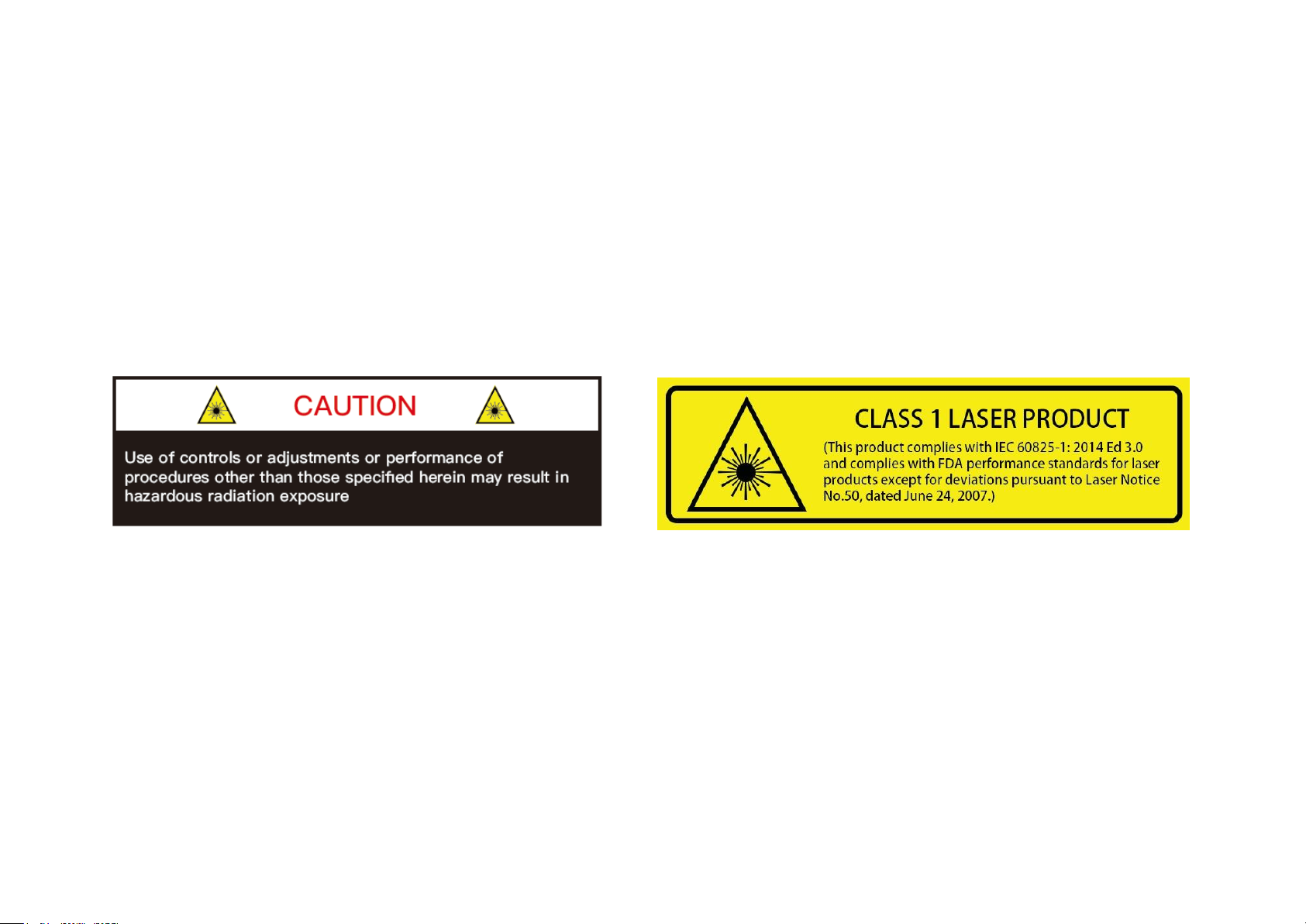
◼ Laser Safety Notice – Laser Class 1
This device satisfies the requirements of
• IEC 60825-1:2014
• 21 CFR 1040.10 and 1040.11 except for deviations pursuant to Laser Notice No.50, dated June 24, 2007
NEVER LOOK INTO THE TRANSMITTING LASER THROUGH A MAGNIFYING DEVICE (MICROSCOPE, EYE LOUPE, MAGNIFYING GLASS, ETC.)

◼ Safety Precautions
In all circumstances, if you suspect that the device malfunctions or is
damaged, stop using it immediately to avoid potential hazards and injuries.
Contact an authorized Hesai Technology service provider for more
information on device disposal.
Handling
This device contains metal, glass, plastic, as well as sensitive electronic
components. Improper handling such as dropping, burning, piercing, and
squeezing may cause damage to the device.
Enclosure
This device contains high-speed rotating parts. To avoid potential injuries,
DO NOT operate the device if the enclosure is loose or damaged.
Repair
DO NOT open and repair the device without direct guidance from Hesai
Technology. Disassembling the LiDAR may cause degraded performance,
failure in water resistance, or potential injuries to the operator.
Power Supply
Use only the cables and power adapters provided by Hesai Technology.
Only the power adapters that meet the device’s power requirements and
the applicable safety standards can be used. Using damaged
cables/adapters or supplying power in a humid environment can result in
fire, electric shock, personal injuries, product damage, or property loss.
Prolonged Exposure to Hot Surface
Prolonged exposure to the device’s hot surface may cause discomfort or
injury. If the device has been powered and operating for a long time, avoid
skin contact with the device and its power adapter.
Vibration
Strong vibration may cause damage to the device and should be avoided.
The device can withstand a sudden impact of 50 G for 11 milliseconds, or
3.21 Grms short-term vibration within 5 Hz to 2000 Hz for 4 hours.
Radio Frequency Interference
Please observe the signs and notices on the device that prohibit or restrict
the use of electronic devices. Although the device is designed, tested, and
manufactured to comply with the regulations on RF radiation, the radiation
from the device may still influence other electronic devices.
Medical Device Interference
Some components in the device can emit electromagnetic fields, which
may interfere with medical devices such as cochlear implants, heart
pacemakers and defibrillators. Consult your physician and medical device
manufacturers for specific information regarding your medical device and
whether you need to keep a safe distance from the LiDAR. If you suspect
that the LiDAR is interfering with your medical device, stop using the LiDAR
immediately.
Explosive Atmosphere and Other Air Conditions
Do not use the device in any area where potentially explosive atmospheres
are present, such as high concentrations of flammable chemicals, vapors or
particulates (including particles, dust, and metal powder) in the air.
Exposing the device to high concentrations of industrial chemicals,
including liquefied gases that are easily vaporized (such as helium), can
damage or weaken the device’s function. Please observe all the signs and
instructions on the device.
Light Interference
Some precision optical instruments may be interfered by the laser light
emitted from the device.
Eye Safety
Although the device meets Class 1 eye safety standards, operators should
still avoid looking directly at the LiDAR for maximum self-protection.

Contents
1 Introduction ............................................................................................................ 1
1.1 Operating Principle ................................................................................................. 1
1.2 LiDAR Structure ........................................................................................................ 2
1.3 Channel Distribution ............................................................................................... 3
1.4 Specifications ............................................................................................................ 4
2 Setup ......................................................................................................................... 5
2.1 Mechanical Installation ........................................................................................... 5
2.2 Interfaces .................................................................................................................... 8
2.3 Connection Box (Optional) ................................................................................... 9
2.4 Get Ready to Use ................................................................................................... 12
3 Data Structure ...................................................................................................... 13
3.1 Point Cloud Data Packet ...................................................................................... 14
3.2 GPS Data Packet ..................................................................................................... 17
4 Web Control ......................................................................................................... 23
4.1 Home ......................................................................................................................... 24
4.2 Settings ..................................................................................................................... 25
4.3 Azimuth FOV ........................................................................................................... 28
4.4 Operation Statistics ............................................................................................... 31
4.5 Upgrade .................................................................................................................... 32
5 PandarView ........................................................................................................... 33
5.1 Installation ................................................................................................................ 33
5.2 Use ............................................................................................................................. 34
5.3 Features .................................................................................................................... 36
6 Communication Protocol .................................................................................. 40
6.1 Packet Structure ..................................................................................................... 40
6.2 Command Description ......................................................................................... 41
7 Sensor Maintenance ........................................................................................... 49
8 Troubleshooting .................................................................................................. 50
Appendix I Channel Distribution ........................................................................ 52
Appendix II Absolute Time and Laser Firing Time ......................................... 54
Appendix III PTP Protocol .................................................................................... 57
Appendix IV Phoenix Contact ............................................................................. 59
Appendix V Nonlinear Reflectivity Mapping ................................................... 60
Appendix VI Certification Info ............................................................................ 64
Appendix VII Support and Contact .................................................................... 65
1
1 Introduction
This manual describes the specifications, installation, and data output format of Pandar40P.
This manual is under constant revision. Please contact Hesai for the latest version.
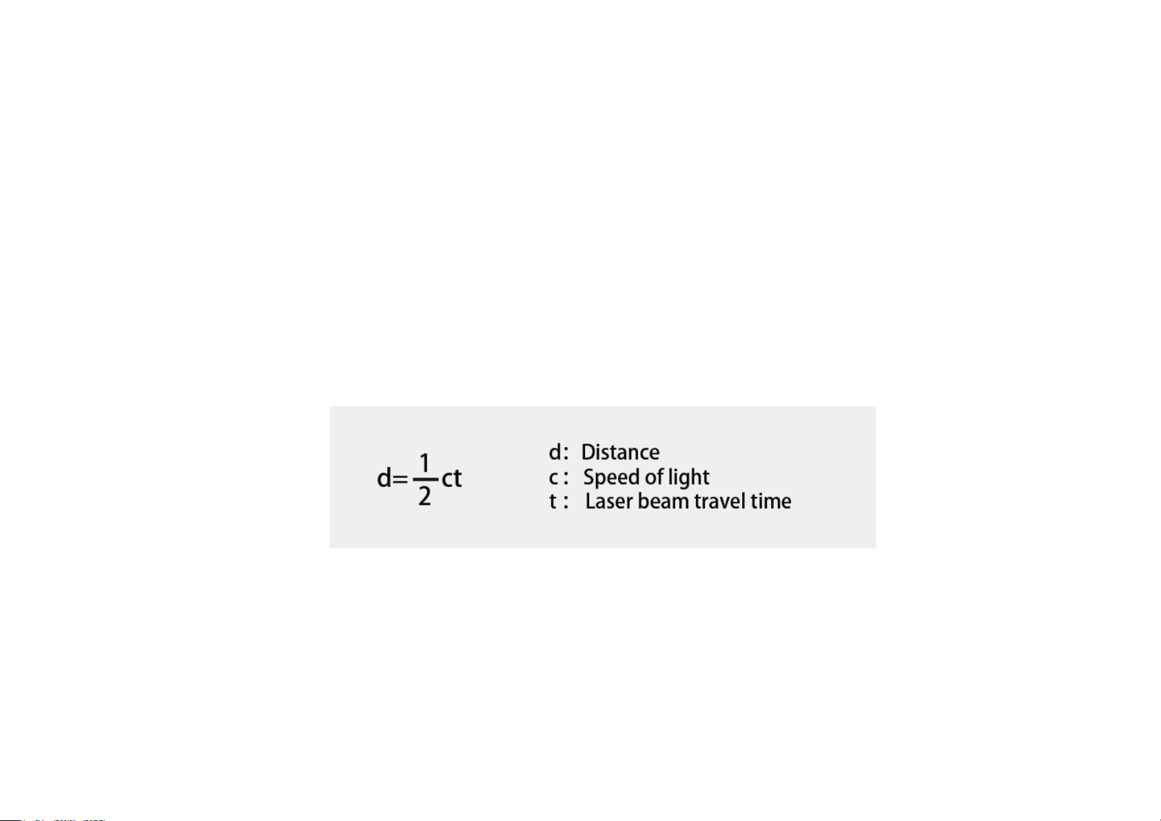
1.1 Operating Principle
Distance Measurement: Time of Flight (ToF)
1) A laser diode emits a beam of ultrashort laser pulses onto the object.
2) Diffuse reflection of the laser occurs upon contact with the target object. The beams are detected by the optical sensor.
3) Distance to object can be accurately measured by calculating the time between emission and receipt by the sensor.
Figure 1.1 ToF Formula
2
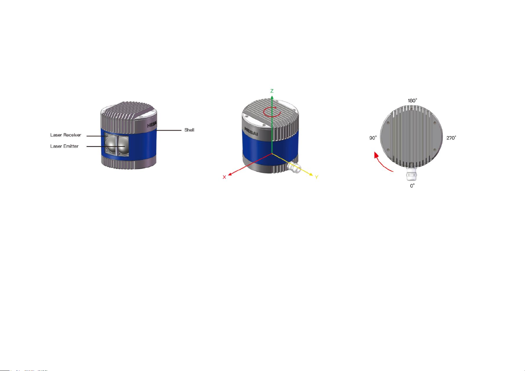
1.2 LiDAR Structure
40 pairs of laser emitters and receivers are attached to a motor that rotates horizontally.
Figure 1.2 Partial Cross-Sectional Diagram
Figure 1.3 Coordinate System (Isometric View)
Figure 1.4 Rotation Direction (Top View)
The LiDAR’s coordinate system is shown above. The Z-axis is the axis of rotation.
The origin is shown as a red dot in Figure 1.6 on the next page. After geometric transforms, all the measurements are relative to the origin.
Each laser channel has an intrinsic horizontal angle offset. When Channel 12 passes the zero degree position (y-axis) illustrated in Figure 1.4, the azimuth
data in the corresponding UDP data block will be 0°.
3
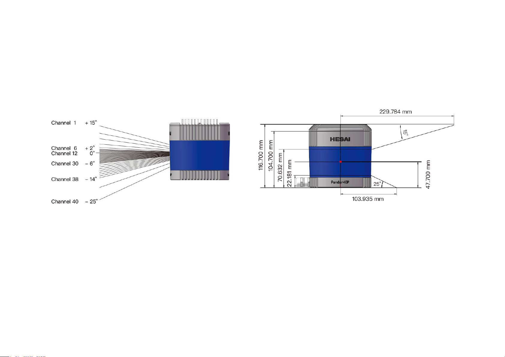
1.3 Channel Distribution
The vertical resolution is
• 0.33° between Channel 6 and Channel 30
• 1° between Channel 5 and Channel 6, Channel 30 and Channel 38
• not evenly distributed in the remaining channels, as detailed in Appendix I
Figure 1.5 Channel Vertical Distribution
Figure 1.6 Laser Firing Position

4
1.4 Specifications
NOTE Specifications are subject to change without notice.
NOTE Range accuracy as the average range error across all channels may vary with range, temperature and target reflectivity.
SENSOR
MECHANICAL/ELECTRICAL/OPERATIONAL
Scanning Method
Mechanical Rotation
Wavelength
905 nm
Channel
40 Laser Class
Class 1 Eye Safe
Range
0.3 to 200 m (at 10% reflectivity)
Ingress Protection
IP6K7
Range Accuracy
±5 cm (0.3 to 1 m)
±2 cm (1 to 200 m)
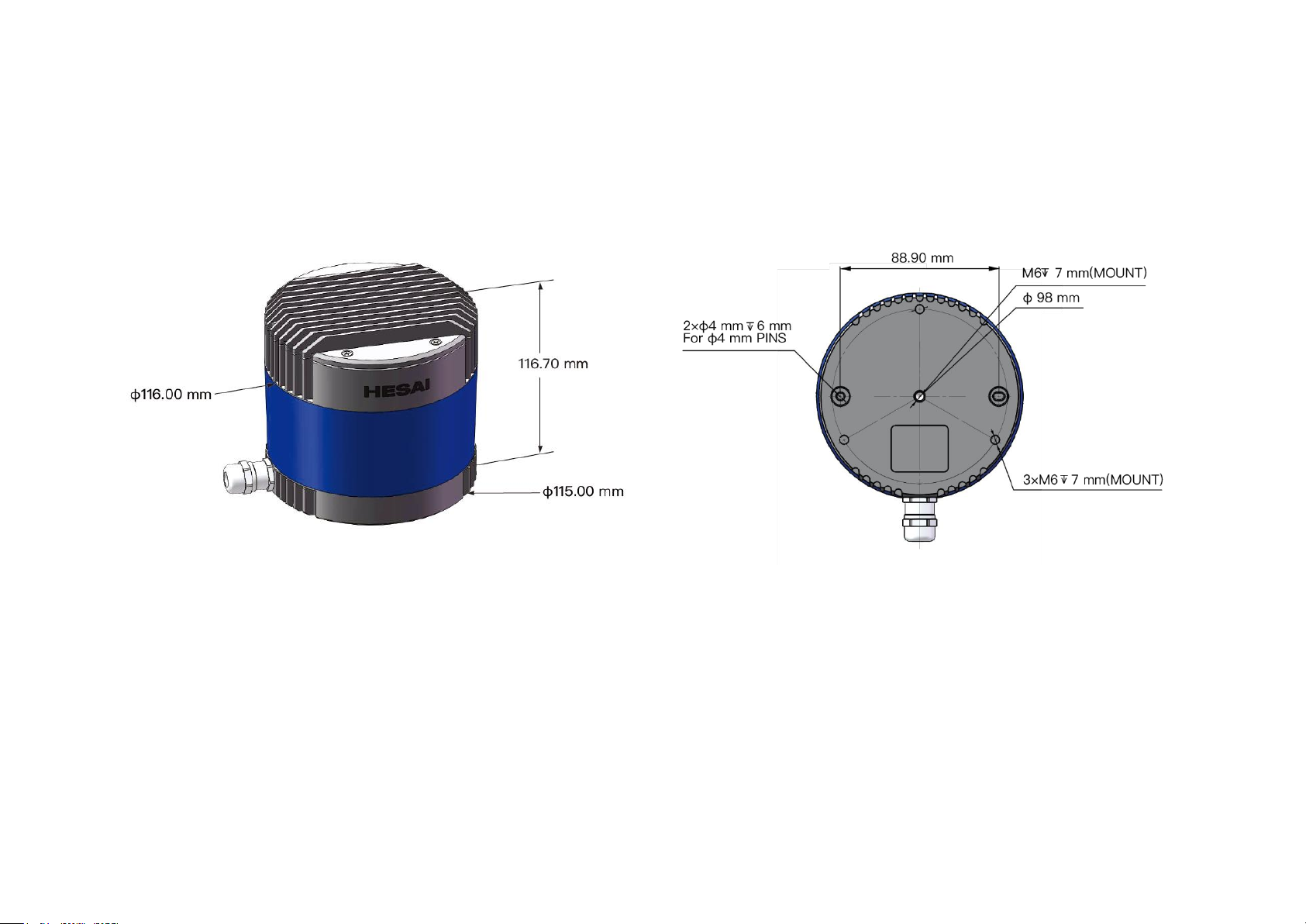
Dimensions
Height: 116.7 mm
Top/Bottom Diameter: 116.00 / 115.00 mm
FOV (Horizontal)
360°
Operating Voltage
DC 9 to 48 V
Resolution (Horizontal)
0.2° (10 Hz), 0.4° (20 Hz)
Power Consumption
18 W
FOV (Vertical)
40° (-25° to +15°)
Operating Temperature
-20℃ to 65℃
Resolution (Vertical)
0.33° (-6° to +2°);
1° (+2° to +3°, -14° to -6°);
2° (+3° to +5°);
3° (+5° to +11°);
4° (+11° to +15°);
5° (-19° to -14°);
6° (-25° to -19°)
Certifications
RoHS, REACH, WEEE
CE, FCC, IC, EAC, KCC
Weight
1.52 kg
DATA I/O
Data Transmission
UDP/IP Ethernet (100 Mbps)
Frame Rate
10 Hz, 20 Hz
Data Outputs
Distance, Azimuth Angle, Intensity
Returns
Single and Dual Returns
(Strongest, Last)
Data Points Generated
Single Return Mode: 720,000 points per second
Dual Return Mode: 1,440,000 points per second
Clock Source
GPS / PTP
PTP Clock Accuracy
≤1 μs
PTP Clock Drift
≤1 μs/s
5
2 Setup
2.1 Mechanical Installation
Figure 2.1 Isometric View
Figure 2.2 Bottom View
6
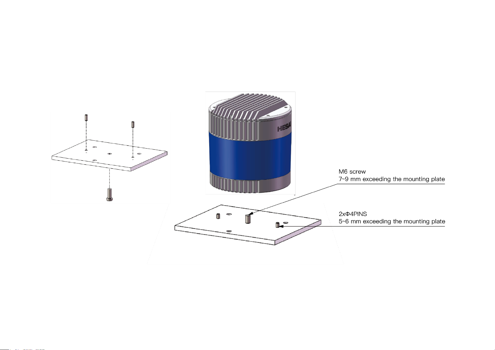
◼ Quick Installation
Figure 2.3 Diagram of Quick Installation
7
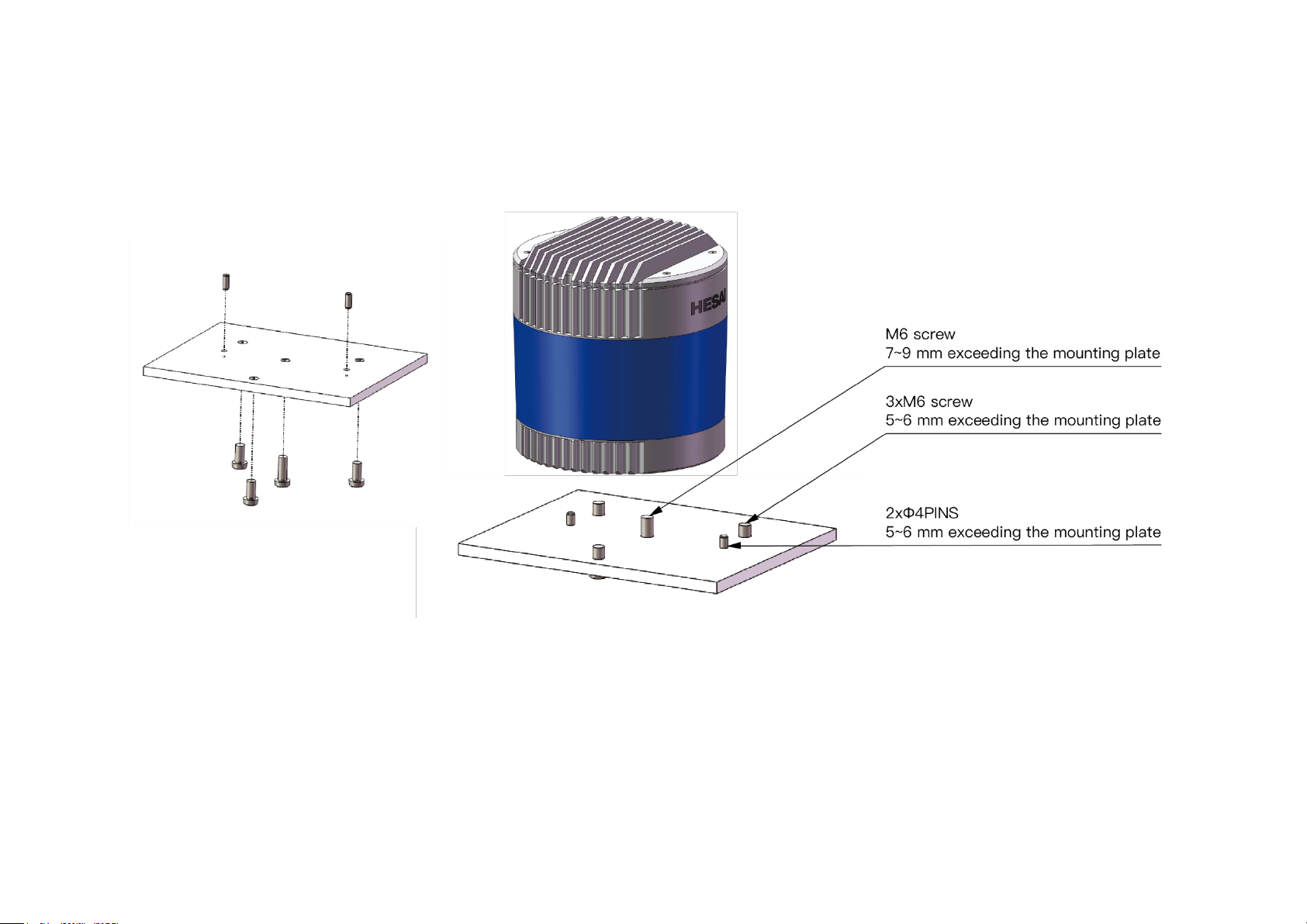
◼ Stable Installation
Figure 2.4 Diagram of Stable Installation
8
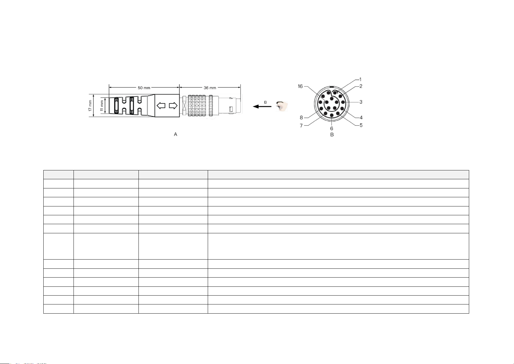
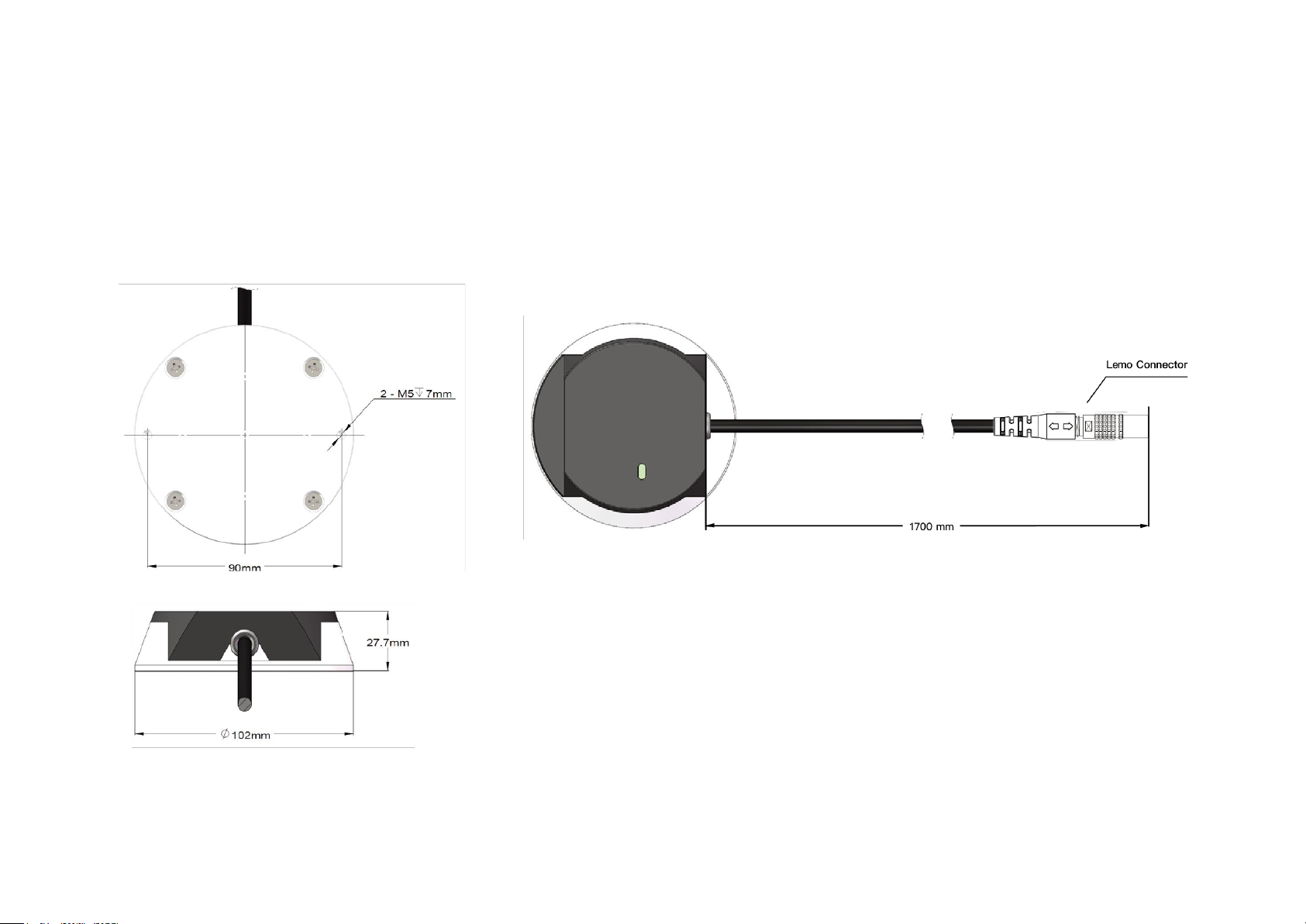
2.2 Interfaces
Lemo Contact is the default communication connector. (Another option is the Phoenix Contact, detailed in Appendix IV.)
Lemo part number: FGG.2T.316.CLAC75Z (male, on the LiDAR)
From the eye to
the interface
Figure 2.5 Lemo Connector (Male)
Table 2.1 Pin Description of Lemo Connector
Pin #
Function
Color
Voltage
1 ~ 4
- - - 5 Ethernet RX-
BLUE
-1 V to 1 V
6
Ethernet RX+
BLUE/WHITE
-1 V to 1 V
7
Ethernet TX-
ORANGE
-1 V to 1 V
8
Ethernet TX+
ORANGE/WHITE
-1 V to 1 V
9
GPS Serial Data
WHITE
-13 V to +13 V
10
GPS PPS
YELLOW
TTL level 3.3 V/5 V
Pulse width: 1 ms or longer is recommended
Cycle: 1 s (from rising edge to rising edge)
11
P12V
RED
12 V
12
P12V
GRAY
12 V
13
Ground (Return)
BLACK
0
14
Ground (Return)
GRAY/WHITE
0
15 - PURPLE
-
16 - PURPLE/WHITE
-
The cable length from the LiDAR exit to the tip of the connector is 0.3 m.
9
2.3 Connection Box (Optional)
Users may connect the LiDAR directly or using the connection box.
The connection box comes equipped with a power port, a GPS port, and a standard Ethernet port.
The cable length between the connector and the connection box is 1.7 m by default.
Lemo part number: PHG.2T.316.CLLC75Z (female, on the connection box)
Figure 2.6 Connection Box
10
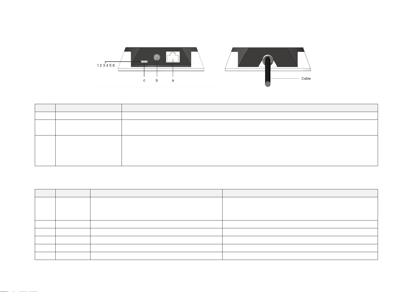
2.3.1 Connection Box Interfaces
Figure 2.7 Connection Box
Table 2.2 Connection Box Interfaces
Port #
Port Name
Description
a
Standard Ethernet Port
RJ45, 100 Mbps Ethernet
b
Power Port
Use DC-005 DC power adapter
Input voltage ranges from 9 V to 48 V. Power consumption is 18 W
c
GPS Port
Connector type: JST SM06B-SRSS-TB
Recommended connector for the external GPS module: JST SHR-06V-S-B
Voltage standard: RS232
Baud rate: 9600 bps
The GPS port pin numbers are 1 to 6 from left to right, defined as follows:
Table 2.3 GPS Pin Description
Pin #
Direction
Pin Description
Requirements
1
Input
PPS (pulse-per-second) signal for synchronization
TTL level 3.3 V/5 V
Pulse width: 1 ms or longer is recommended
Cycle: 1 s (from rising edge to rising edge)
2
Output
Power for the external GPS module
5 V 3 Output
Ground for the external GPS module
- 4 Input
Receiving serial data from the external GPS module
RS232 level
5
Output
Ground for the external GPS module
- 6 Output
Transmitting serial data to the external GPS module
RS232 level
11
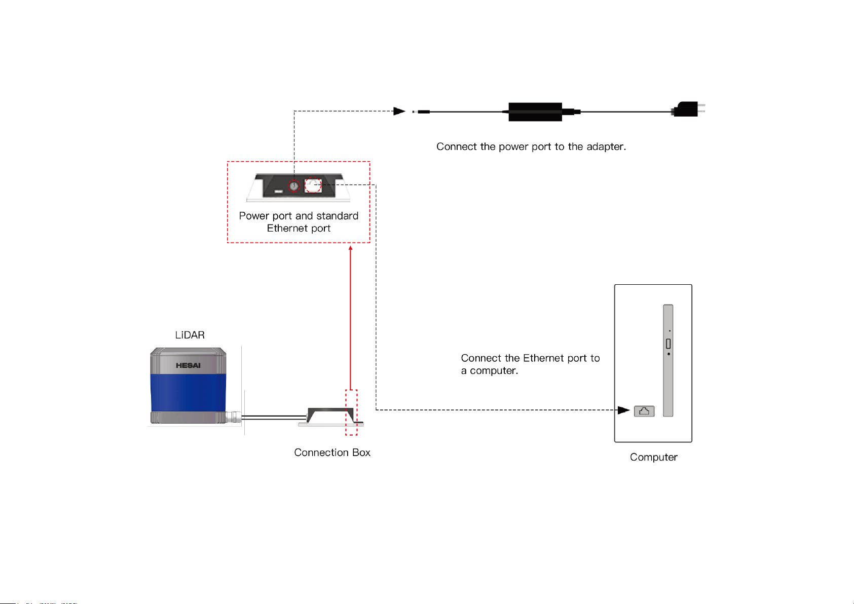
2.3.2 Connection
Figure 2.8 LiDAR Connection When Using the Connecting Box
NOTE Refer to Appendix III when PTP protocol is used.

12
2.4 Get Ready to Use
The LiDAR does not have a power switch. It starts operating once connected to power and the Ethernet.
• To receive data on your PC, set the PC’s IP address to 192.168.1.100 and subnet mask to 255.255.255.0
For Ubuntu-16.04:
For Windows:
Use the ifconfig command in the terminal:
~$ sudo ifconfig enp0s20f0u2 192.168.1.100
(replace enp0s20f0u2 with the local network port name)
1) Open the Network Sharing Center, click on “Ethernet”
2) In the “Ethernet Status” interface, click on “Properties”
3) Double-click on “Internet Protocol Version 4 (TCP/IPv4)”
4) Configure the IP address to 192.168.1.100 and subnet mask to 255.255.255.0
• To record and display point cloud data, see Chapter 5 PandarView
• To set parameters, check device info, or upgrade firmware, see Chapter 4 Web Control
• The SDK (Software Development Kits) download links can be found at www.hesaitech.com/en/download
13
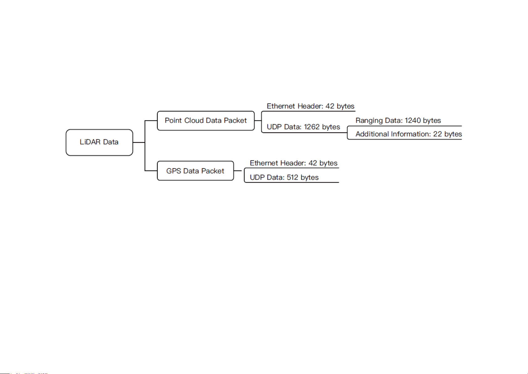
3 Data Structure
100 Mbps Ethernet UDP/IP is used for data output. The output data includes Point Cloud Data Packets and GPS Data Packets. Each data packet consists of
an Ethernet header and UDP data.
Figure 3.1 Data Structure with UDP Sequence OFF
The UDP sequence feature is OFF by default. When UDP sequence is ON, the Additional Information in the UDP data changes from 22 bytes to 26 bytes.
14
3.1 Point Cloud Data Packet
3.1.1 Ethernet Header
Each LiDAR has a unique MAC address.
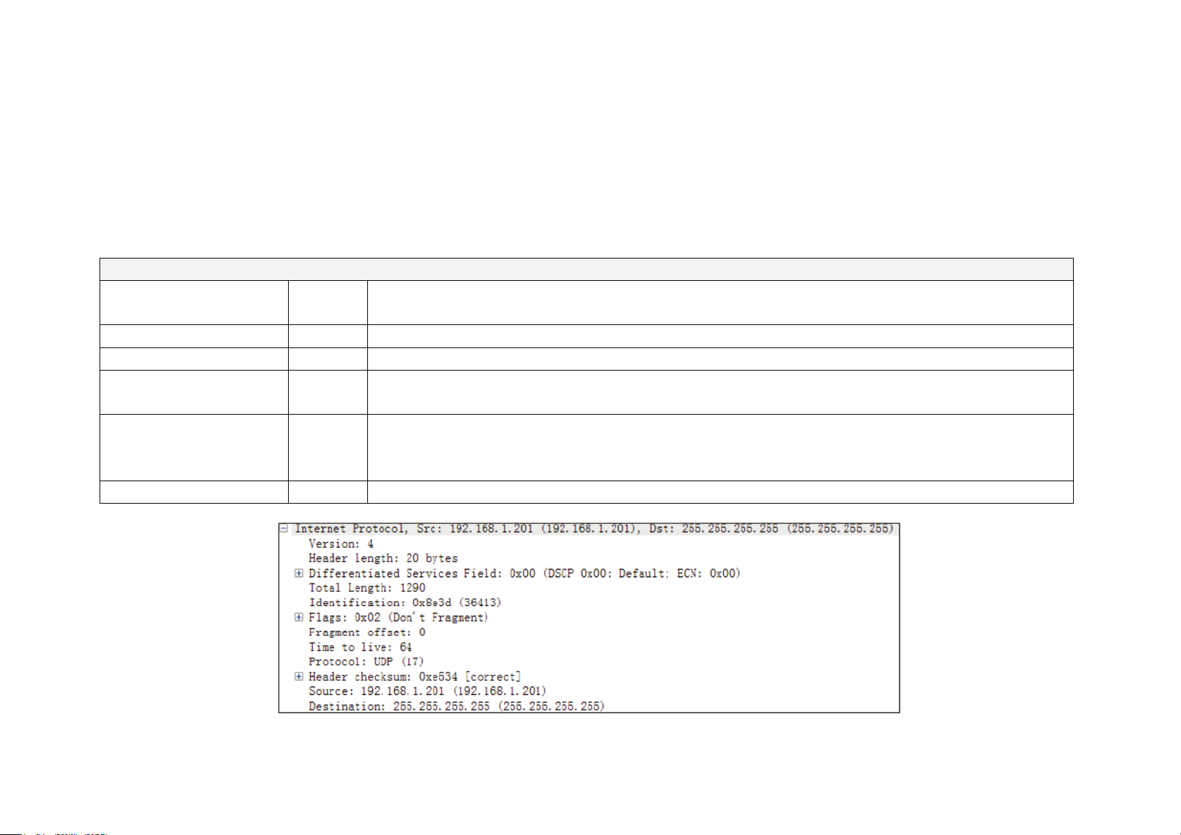
The source IP is 192.168.1.201 by default. The destination IP address is 0xFF FF FF FF and in broadcast form.
Table 3.1 Point Cloud Data Packet – Ethernet Header
Ethernet Header: 42 bytes
Ethernet II MAC
12 bytes
Destination: broadcast (0xFF: 0xFF: 0xFF: 0xFF: 0xFF: 0xFF)
Source: (xx:xx:xx:xx:xx:xx)
Ethernet Data Packet Type
2 bytes
0x08, 0x00
Internet Protocol
20 bytes
Shown in the figure below
UDP Port Number
4 bytes
UDP source port (0x2710, representing 10000)
Destination port (0x0940, representing 2368)
UDP Length
2 bytes
0x04F6 when UDP sequence is OFF, representing 1270 bytes (8 bytes more than the size of the Point Cloud
UDP Data, shown in Figure 3.1)
0x04FA when UDP sequence is ON, representing 1274 bytes
UDP Checksum
2 bytes
-
Figure 3.2 Point Cloud Ethernet Header – Internet Protocol

15
3.1.2 UDP Data
All the multi-byte values are unsigned and in little endian format.
Ranging Data
Table 3.2 Point Could UDP Data – Ranging Data
Ranging Data: 1240 bytes (10 blocks)
Block 1
Block 2
Block 3
…
Block 10
0xFFEE
0xFFEE
0xFFEE
…
0xFFEE
Azimuth 1
Azimuth 2
Azimuth 3
…
Azimuth 10
Channel 1
Channel 1
Channel 1
…
Channel 1
Channel 2
Channel 2
Channel 2
…
Channel 2
… … … … …
Channel 40
Channel 40
Channel 40
…
Channel 40
Table 3.3 Point Cloud UDP Data - Block Definition
Each block in the Ranging Data: 124 bytes
0xFFEE
2 bytes
Header, meaningless, 0xFF first
Azimuth
2 bytes
Current reference angle of the rotor
Azimuth[15:0]: lower byte Azimuth_L[7:0], upper byte Azimuth_H[15:8]
Azimuth Angle = [Azimuth_H, Azimuth_L] / 100° = Azimuth / 100°
Channel XX
3 bytes
2-byte distance data
Distance[15:0]: lower byte Distance_L[7:0], upper byte Distance_H[15:8]
Distance Value = [Distance_H, Distance_L] * 4 mm = Distance * 4
Maximum Distance Value = (2 ^ 16 – 1) * 4 mm = 262.14 m
1-byte reflectivity data
Reflectivity, in percentage (0 to 255%)
NOTE Under the Dual Return mode, the ranging data from each firing is stored in two adjacent blocks: the odd number block is the last return, and the
even number block is the strongest return. If the last and strongest returns coincide, the second strongest return will be placed in the even number block.
The azimuth changes every two blocks.

16
Additional Information
Table 3.4 Point Cloud UDP Data – Additional Information
Additional Information: 22/26 bytes when UDP sequence is OFF/ON
Reserved
5 bytes
-
High Temperature Shutdown
Flag
1 byte
0x01 for high temperature; 0x00 for normal operation
• When high temperature is detected, the shutdown flag will be set to 0x01, and the system will shut
down after 60 s. The flag remains 0x01 during the 60 s and the shutdown period
• When the system is no longer in high temperature status, the shutdown flag will be reset to 0x00 and
the system will automatically return to normal operation
Reserved
2 bytes
-
Motor Speed
2 bytes
speed_2_bytes[15:0] = speed (RPM)
GPS Timestamp
4 bytes
Packing time of this data packet, in units of 1 μs
Range: 0 to 1000000 μs (1 s)
Return Mode Information
1 byte
0x37 for Strongest Return mode, 0x38 for Last Return mode, and 0x39 for Dual Return mode
Factory Information
1 byte
0x42 (or 0x43)
UTC
6 bytes
UTC time in decimal: year, month, date, hour, minute, second
UDP Sequence
4 bytes
Added only when UDP sequence is ON
Label the sequence number of Point Cloud UDP packets, 1 to 0xFF FF FF FF in little endian format
Example of UDP Data Analysis in Point Cloud Data Packets
Take Pandar40P’s Channel 5 in Block 3 of the UDP Data as an example:
1) Vertical angle of Channel 5 is 3.00°, according to Appendix I Channel Distribution
2) Horizontal angle is the current reference angle of the rotor (Azimuth of Block 3) plus the horizontal angle offset (-1.042°, according to Appendix I).
Define clockwise in the top view as the horizontal angles’ positive direction
3) The 2-byte distance data in the UDP Data Packet, multiplied by 4 mm, is the actual distance in real world millimeters
After determining the horizontal angle, vertical angle, and distance of a data point, this point can be drawn in a polar or rectangular coordinate system. The
real-time point cloud data is drawn by analyzing every point in the UDP data.

17
3.2 GPS Data Packet
GPS Data Packets are triggered every second. All the multi-byte values are unsigned and in little endian format.
Before NMEA messages are available from the external GPS module
Each rising edge of the LiDAR’s internal 1 Hz signal triggers a GPS Data Packet.
The time and date in the GPS Data Packets are unreal, starting from 00 01 01 00 00 00 (year, month, day, hour, minute, second) and increasing with the
internal 1 Hz signal.
Once the LiDAR receives the PPS (pulse-per-second) signal and NMEA messages
The internal 1 Hz signal will be locked to the PPS. Each rising edge still triggers a GPS Data Packet.
Meanwhile, the LiDAR will extract the actual UTC time and date from NMEA messages ($GPRMC or $GPGGA), and stamp them into both Point Cloud Data
Packets and GPS Data Packets.
• Point Cloud Data Packets: 6-byte UTC Time (year, month, day, hour, minute, second) in decimal
• GPS Data Packets: 6-byte Date (year, month, day) and 6-byte Time (second, minute, hour) in ASCII
The GPS module sends first the PPS signal and then the NMEA message. At the rising edge of the PPS pulse, the corresponding NMEA message is not yet
available. Therefore, the LiDAR extracts UTC information from the previous NMEA message and automatically adds 1 full second.
When GPS signal is lost
The LiDAR will still trigger GPS Data Packets by the rising edge of the internal 1 Hz signal. However, the GPS time in the packets will be counted by the
internal 1 Hz signal and will drift from the actual GPS time.

18
3.2.1 Ethernet Header
The source IP is 192.168.1.201 by default. The destination IP address is 0xFF FF FF FF and in broadcast form.
Table 3.5 GPS Data Packet – Ethernet Header
Ethernet Header: 42 bytes
Ethernet II MAC
12 bytes
Destination: broadcast (0xFF: 0xFF: 0xFF: 0xFF: 0xFF: 0xFF)
Source: (xx:xx:xx:xx:xx:xx)
Ethernet Data Packet Type
2 bytes
0x08, 0x00
Internet Protocol
20 bytes
Shown in the figure below
UDP Port Number
4 bytes
UDP source port (0x2710, represents 10000)
Destination port (0x277E, represents 10110)
UDP Length
2 bytes
0x208, representing 520 bytes (8 bytes more than the size of the GPS UDP Data, shown in Figure 3.1)
UDP Checksum
2 bytes
-
Figure 3.3 GPS Ethernet Header – Internet Protocol

19
3.2.2 UDP Data
Table 3.6 GPS Data Packet – UDP Data
GPS UDP data: 512 bytes
GPS time data
18 bytes
Header
2 bytes
0xFFEE, 0xFF first
Date
6 bytes
Year, month, and day (2 bytes each, lower byte first) in ASCII
Time
6 bytes
Second, minute, and hour (2 bytes each, lower byte first) in ASCII
μs Time
4 bytes
In units of μs (lower byte first)
GPRMC/GPGGA data
84 bytes
ASCII code, valid till 2 bytes after ‘*’
NMEA sentence that contains the UTC time information
Users can select either GPRMC or GPGGA in the Settings page of web control, as shown in Section 4.2
reserved
404 bytes
404 bytes of 0xDF
GPS positioning status
1 byte
ASCII code, obtained from $GPRMC or $GPGGA
When $GPRMC is selected:
When $GPGGA is selected:
A (hex = 41) for Valid Position
V (hex = 56) for Invalid Position
NUL (hex = 0) for GPS being unlocked
0 = invalid
1 = GPS fix (SPS)
2 = DGPS fix
3 = PPS fix
6 = estimated (dead reckoning)
flag of PPS lock
1 byte
1 – locked 0 – unlocked
reserved
4 bytes
-

20
GPRMC Data Format
$GPRMC, <01>, <02>, <03>, <04>, <05>, <06>, <07>, <08>, <09>, <10>, <11>, <12>*hh
Field #
Field
Description
<01>
UTC Time
Hour, minute, and second
Can be in hhmmss (hour, minute, second) format
<02>
Location Status
A (hex = 41) for Valid Position
V (hex = 56) for Invalid Position
NUL (hex = 0) for GPS being unlocked
…
<09>
UTC Date
Date information
Can be in ddmmyy (day, month, year) format
…
The LiDAR’s GPS data interface is compatible with a variety of GPRMC formats, as long as:
<01> is the hour, minute, and second information
<09> is the date information.
For example, the following two formats are both acceptable:
$GPRMC,072242,A,3027.3680,N,11423.6975,E,000.0,316.7,160617,004.1,W*67
$GPRMC,065829.00,A,3121.86377,N,12114.68322,E,0.027,,160617,,,A*74

21
GPGGA Data Format
$GPGGA, <01>, <02>, <03>, <04>, <05>, <06>, <07>, <08>, <09>, <10>, <11>, <12>*hh
Field #
Field
Description
<01>
UTC Time
Hour, minute, and second
Can be in hhmmss (hour, minute, second) format
…
<06>
GPS Fix Quality
0 = invalid 1 = GPS fix (SPS) 2 = DGPS fix 3 = PPS fix 6 = estimated (dead reckoning)
…
The LiDAR’s GPS data interface is compatible with a variety of GPGGA formats, as long as:
<01> is the hour, minute, and second information
For example, the following two formats are both acceptable:
$GPGGA,123519,4807.038,N,01131.000,E,1,08,0.9,545.4,M,46.9,M,,*47
$GPGGA,134658.00,5106.9792,N,11402.3003,W,2,09,1.0,1048.47,M,-6.27,M,08,AAAA*60

22
Example of UDP Data Analysis in GPS Data Packets
Figure 3.4 GPS Data Packet – UDP Data (Example)
Date
Field
Data (ASCII Code)
Characters
Meaning
Year
0x39 0x31
'9', '1'
19
Month
0x32 0x30
'2', '0'
02
Day
0x36 0x32
'6', '2'
26
(UTC) Time
Field
Data (ASCII Code)
Characters
Meaning
Second
0x33 0x35
'3', '5'
53
Minute
0x34 0x35
'4', '5'
54
Hour
0x31 0x31
'1', '1'
11
μs Time
4 bytes, in units of μs, using the same clock source as the GPS Timestamp in Point Cloud Data Packets
Reset to 0 at the rising edge of each PPS signal

23
4 Web Control
Web control is used for setting parameters, checking device info, and upgrading.
To access web control
1) Connect the LiDAR to your PC using an Ethernet cable
2) Set the IP address according to Section 2.4 Get Ready to Use
3) Enter this URL into your web browser: 192.168.1.201/index.html
NOTE Use Google Chrome or Firefox instead of IE. Turn off VPN.

24
4.1 Home
Figure 4.1 Home Page of Web Control
Spin Rate of the motor (revs per minute) = frame rate (Hz) * 60
GPS (PPS) Status
Lock
LiDAR’s internal clock is in sync with the GPS
Unlock
Not in sync
NMEA (GPRMC/GPGGA) Status
Lock
After receiving a valid NMEA message
Unlock
Not receiving a valid NMEA message
PTP Status
Free Run
No PTP master is selected; only the LiDAR’s clock is
used
Tracking
Slave is trying to sync with the selected PTP Master,
but the offset is more than 1 μs
Locked
Offset between the Slave and the Master is below 1
μs
Frozen
(Holdover)
LiDAR has lost connection to the PTP master and is
attempting to recover it.
Meanwhile, LiDAR starts drifting from the previous
clock; when drifting out of specifications, it goes back
to the Free Run mode.

25
4.2 Settings
Figure 4.2 Settings Page of Web Control
1. Control IP
VLAN Tagging can be used when the receiving host also supports
VLAN function.
• Check the VLAN checkbox and input a VLAN ID (range:
1~4094) for the LiDAR unit.
• Set the VLAN ID of the receiving host to be the same.
2. Destination IP
Mode
Destination IP
Broadcast (default)
255.255.255.255
Multicast
239.0.0.0~239.255.255.255
Unicast
Same as the PC’s IP address
3. LiDAR Functions
Spin Rate
600 rpm / 1200 rpm
Return Mode
Last / Strongest / Dual Return
UDP Sequence
OFF / ON #1 / ON #2
OFF by default.
When UDP Sequence is ON, UDP packets
are labeled with a sequence number. See
Section 3.1 for changes in data structure.
ON #1: UDP sequence increments even
though no UDP packet is generated outside
the FOV specified in Section 4.3.
ON #2: UDP sequence increments only
when UDP packets are generated.
(continued on the next page)

26
Figure 4.2 Settings Page of Web Control
(continued)
Sync Angle
0~360 degrees
By default, the LiDAR’s zero-degree position
(defined in Section 1.2) is not in sync with
PPS.
If syncing is needed, check the check box
and input a sync angle.
Noise Filtering
Noise points mitigation in rain and fog
Reflectivity
Mapping
Linear / Nonlinear Mapping
By default, the 1-byte reflectivity data in the
Point Cloud Data Packet linearly represents
target reflectivity from 0 to 255%.
Users can alternatively choose Nonlinear
Mapping to increase the contrast in the lowreflectivity region. See Appendix V Nonlinear
Reflectivity Mapping.
Trigger Method
Angle-Based / Time-Based
In the angle-based trigger mode, lasers fire
every 0.2 deg at 10 Hz or 0.4 deg at 20 Hz.
In the time-based mode, lasers fire every
55.56 us.
Standby Mode
Whether to stop the motor from running
and lasers from firing
4. Reset All Settings
By clicking the Reset All Settings button on the top-right corner,
all configurable parameters in the Settings page and the Azimuth
FOV page will be reset to their default values.
The default values are shown on Figure 4.2 and Figure 4.5.

27
5. Clock Source and PTP Parameters
Clock Source
GPS / PTP
In the PTP mode, LiDARs do not output GPS Data Packets, as detailed in Appendix III
PTP Protocol.
When GPS is selected as the clock source:
GPS Mode
GPRMC / GPGGA
Format of the data received from the external GPS module.
Both the NMEA sentence and the GPS positioning status are put into the GPS Data
Packet. See Section 3.2.2 for details.
When PTP is selected as the clock source:
PTP Domain Number
Integer from 0 to 127
Domain attribute of the local clock
PTP Network Transport
UDP/IP (default) or L2
UDP/IP follows the PTPv2 standard defined in IEEE 1588-2008
PTP logAnnounceInterval
-2 to 3 log seconds
Time interval between Announce messages (default: 1)
PTP logSyncInterval
-7 to 3 log seconds
Time interval between Sync messages (default: 1)
PTP logMinDelayReqInterval
-7 to 3 log seconds
Minimum permitted mean time between Delay_Req messages (default: 0)
Figure 4.3 Settings Page of Web Control – PTP Parameters

28
4.3 Azimuth FOV
For Azimuth FOV Setting, users can select one of the three modes.
Figure 4.4 Azimuth FOV Page of Web Control
4.3.1 For all channels
A continuous angle range, specified by a start angle and an end angle, will be applied to all the channels.
Outside the specified angle range, there will be no laser firing or data generated.
NOTE Click “Save” to apply your settings.
Figure 4.5 Azimuth FOV for All Channels

29
4.3.2 For each channel
Users can configure one continuous angle range for each channel.
Outside the specified range for each channel, there will be no laser firing or data generated in that channel.
By default, the status button for each channel is green, indicating that angle range configuration is active.
To deactivate the angle range configuration for one channel, click the corresponding button to make it gray. Thus the angle range for this channel
becomes [0°,360°].
Click the “Enable/Disable All” button to activate/deactivate the angle range configuration for all channels.
NOTE Click “Save” to apply your settings.
·
·
·
Figure 4.6 Azimuth FOV for Each Channel

30
4.3.3 Multi-section FOV
Users can configure up to ten continuous angle ranges (i.e. sections) for each channel.
By default, the status button for each channel is green, indicating that multi-section configuration is active.
To deactivate the multi-section configuration for one channel, click the corresponding button to make it gray. Thus the angle range for this channel
becomes [0°,360°].
Click the “Enable/Disable All” button to activate/deactivate the angle range configuration for all channels.
· · ·
· ·
· ·
· ·
Figure 4.7 Multi-Section Azimuth FOV

31
4.4 Operation Statistics
The LiDAR's operation time in aggregate and in different temperature ranges are listed.
Figure 4.8 Operation Statistics Page of Web Control

32
4.5 Upgrade
Click the Upload button and select an upgrade file (provided by Hesai). Reboot the LiDAR when the upgrade is complete.
Below shows the software and firmware versions described in this manual.
NOTE A software reboot is triggered by clicking the Restart button on the top right corner. Afterwards, the start-up counts in the Operation Statistics page
increments by 1.
Figure 4.9 Firmware Upgrade Page of Web Control

33
5 PandarView
PandarView is a software that records and displays the point cloud data from Hesai LiDARs, available in 64-bit Windows 7/8/10 and Ubuntu-16.04.
5.1 Installation
Copy the installation files from the USB disk included in the LiDAR’s protective case, or download these files from Hesai’s official website:
www.hesaitech.com/en/download
NOTE Separate Python installation is required only for older PandarView versions.
System
Installation Files
Installation Steps
Windows
PandarView_Windows_V1.6.9.msi
python-2.7.13.msi
When upgrading PandarView to a newer version, please uninstall the current version
Double click and install python
Use the default settings in the setup wizard, including “install for all users”
Double click and install PandarView_Windows using the default settings
Ubuntu-16.04
PandarView_Installer_V1.6.9.tar.gz
Enter the following command in the terminal:
sudo apt-get install qt4-default libboost-all-dev
Unzip PandarView_Installer.tar.gz and run PandarView_Installer.bin
This manual describes PandarView 1.6.9. Users can check the software version from “About” in the menu bar.
Figure 5.1 Menu and Buttons (PandarView 1.6.9)

34
5.2 Use
Set the PC’s IP address according to Section 2.4 Use.
◼ Check Live Data
◼ Open a PCAP File
Click on and select your LiDAR model to begin receiving data over
Ethernet.
Click on to pop up the “Choose Open File” window. Select a PCAP
file to open.
◼ Record a PCAP File
◼ Import a Correction File
Click on to pop up the “Choose Output File” window.
Click on “Save” to begin recording a PCAP file.
Click on again to stop recording.
Figure 5.2 Choose Output File
Each LiDAR comes with a correction file (.CSV) in the provided USB disk.
When a PCAP file is open, click on “File” in the menu bar and “Import
Correction File”.
Figure 5.3 File Menu

35
◼ Play a PCAP File
Button
Description
Jump to the beginning of the file
While paused, jump to the previous frame
While playing, rewind. May click again to adjust the rewind speed (2x, 3x, 1/2x,
1/4x, and 1x)
/
After loading a point cloud file, click to play the file
While playing, click to pause
While paused, jump to the next frame.
While playing, forward. May click again to adjust the forward speed (2x, 3x, 1/2x,
1/4x, and 1x)
Jump to the end of the file
Save a single frame to .CSV (the XYZ coordinates as the first three columns)
While playing, this Record button will be gray and unclickable
While playing, click to loop playback. Otherwise the player will stop at the end of the file
Save multiple frames to .PCAP
Specify the start and end frames
Save multiple frames to .CSV (the XYZ coordinates as the last three columns)
Drag this progress bar or enter a frame number to jump to a specific frame

36
5.3 Features
◼ Viewpoint Selection
◼ 3D Projection and Distance Measurement
Users can select from the right view, front view, and top view.
Both perspective projection (default) and orthographic projection are supported.
The distance measurement ruler is available only under orthographic projection.
After clicking on , drag your mouse while holding the Ctrl key to make a
measurement in units of meters. Click on again to quit.
◼ Mouse Shortcuts
◼ Distance Reference Circles
• Slide the scroll wheel up/down to magnify/minimize
• Drag while holding the left button to adjust the point of view
• Drag while holding the scroll wheel to pan
NOTE The bottom-left
coordinate axes show the
current point of view
Click on to show/hide the 12 distance reference circles in gray. The actual
distances are marked below.
To change the color and line width of these circles, click on “Tools” in the menu
bar and open “Grid Properties”.

37
◼ Return Mode
◼ UDP Port
Users can select from Block 1 Return (i.e. Last Return), Block 2 Return (i.e.
Strongest Return), and Dual Return.
Enter the UDP port number, and click “Set” to apply it.
◼ Channel Selection
Click on to show/hide point cloud data from the selected laser channels.
Check/Uncheck the boxes on the left to show/hide each channel.
Check the “Enable/Disable all” option at the bottom of the table to show/hide all channels.

38
◼ Point Selection and Data Table
Click on and drag the mouse over the point cloud to highlight an area of points.
Click on to view the data of the highlighted points, as shown below.
Some of the data fields are defined below:
Field
Description
points
The XYZ coordinates of each point
azimuth
Rotor’s current reference angle
azimuth_calib
Azimuth + horizontal angle offset
To cancel the selection, click on again and click on any place outside the selected area.

39
◼ Color Schemes.
Click on to show the color legend at the lower right corner.
The default color scheme is intensity based. Users can choose from other colors
schemes based on azimuth, azimuth_calib, distance, elevation, laser_id, or timestamp.
Click on to open or close the Color Editor.

40
6 Communication Protocol
To ensure real-time communication, Hesai’s TCP protocol uses binary format and has disabled Nagle’s algorithm.
6.1 Packet Structure
A client can send command messages to the server (LiDAR). Each command message includes a fixed 8-byte header and a variable command-specific
payload. The header describes the command type and payload length.
Table 6.1 Command Message Sent from Client to LiDAR
Type
Length
Field Description
0x47
1 byte
Fixed content
0x74
1 byte
Fixed content
Cmd
1 byte
Command code. See Section 6.2 Command Description
Return Code
1 byte
Useless
Payload Length
4 bytes
Data length for the command
0x00 – no payload
Payload
Indicated in Payload Length
Additional data for the command
The server (LiDAR) outputs a feedback message for every command it receives.
Table 6.2 Feedback Message from LiDAR to Client
Type
Length
Field Description
0x47
1 byte
Fixed content
0x74
1 byte
Fixed content
Cmd
1 byte
Command code
Return Code
1 byte
Return code from server
Data Length
4 bytes
Data length for the command
0x00 – no payload
Payload
Indicated in Payload Length
Additional data for the command

41
6.2 Command Description
Table 6.3 List of Commands
Command
Command Code
Payload Length
Function
PTC_COMMAND_GET_LIDAR_CALIBRATION
0x5 0 To retrieve the LiDAR’s calibration file
PTC_COMMAND_PTP_DIAGNOSTICS
0x6
1 byte
To retrieve PTP diagnostics for a specified PTP Query Type
PTC_COMMAND_GET_INVENTORY_INFO
0x7 0 To retrieve inventory info
PTC_COMMAND_GET_CONFIG_INFO
0x8 0 To retrieve configuration parameters
PTC_COMMAND_GET_LIDAR_STATUS
0x9 0 To retrieve status info such as temperature and system uptime
◼ PTC_COMMAND_GET_LIDAR_CALIBRATION
Command message payload
None
Feedback message payload
LiDAR’s calibration file in CSV Format (ASCII)
Including 3 fields: LaserID, Elevation, and Azimuth Offset

42
◼ PTC_COMMAND_PTP_DIAGNOSTICS
Command message payload
1-byte PTP Query Type
Table 6.4 PTP Query Type
PTP Query Type
Value
PTP STATUS
0x1
PTP TLV PORT_DATA_SET
0x2
PTP TLV TIME_STATUS_NP
0x3
PTP TLV GRANDMASTER_SETTINGS_NP
0x4
Feedback message payload
a. PTP STATUS
Table 6.5 PTP STATUS
Field
Length
Description
master_offset
8 bytes
Offset between master and slave, in units of ns
ptp_state
4 bytes
"NONE", /*0*/
"INITIALIZING", /*1*/
"FAULTY", /*2*/
"DISABLED", /*3*/
"LISTENING", /*4*/
"PRE_MASTER"/*5*/
"MASTER", /*6*/
"PASSIVE", /*7*/
"UNCALIBRATED", /*8*/
"SLAVE", /*9*/
"GRAND_MASTER", /*10*/
参加 PTP 标准
elapsed_millisec
4 bytes
Time elapsed since the last handshake between master/slave, in milliseconds

43
b. PTP TLV PORT_DATA_SET
Per IEEE-1588 standard management TLV PORT_DATA_SET
Table 6.6 PTP TLV PORT_DATA_SET
Field
Length
Description
portIdentity
10 bytes
Port identity
Including 8-bytes clock identity and 2-byte port number
portState
1 byte
Same as ptp_state in the PTP STATUS message
logMinDelayReqInterval
1 byte
Minimum permitted mean time interval between Delay_Req messages
Specified as a power of two in seconds
Default: 0 (representing 1 second).
peerMeanPathDelay
8 bytes
Peer mean path delay value, in units of ns
logAnnounceInterval
1 byte
Mean time interval between Announce messages of the portDS set
Specified as a power of two in seconds
announceReceiptTimeout
1 byte
Number of missed Announce messages before the last Announce messages of the portDS set expires
logSyncInterval
1 byte
Mean time interval between Sync messages
Specified as a power of two in seconds
delayMechanism
1 byte
Delay mechanism
Possible values: E2E, P2P, and Auto
logMinPdelayReqInterval
1 byte
Minimum permitted mean time interval between Pdelay_Req messages
Specified as a power of two in seconds
versionNumber
1 byte
PTP version number
2 as v2

44
c. LinuxPTP TLV TIME_STATUS_NP (0xc000)
LinuxPTP specific TLV
Table 6.7 LinuxPTP TLV TIME_STATUS_NP
Field
Length
Description
master_offset
8 bytes
Time difference between master and slave at the last handshake, in units of ns
ingress_time
8 bytes
Hardware ingress time stamp of the last sync message received by the slave
cumulativeScaledRateOffset
4 bytes
Relative information in the last received follow_up message
scaledLastGmPhaseChange
4 bytes
Relative information in the last received follow_up message
gmTimeBaseIndicator
2 bytes
Relative information in the last received follow_up message
lastGmPhaseChange
10 bytes
Relative information in the last received follow_up message
gmPresent
4 bytes
Whether grandmaster is present
gmIdentity
8 bytes
Grandmaster identity when gmPresent is 1
d. LinuxPTP TLV GRANDMASTER_SETTINGS_NP (0xc001)
Table 6.8 LinuxPTP TLV GRANDMASTER_SETTINGS_NP
Field
Length
Description
clockQuality
4 bytes
Clock quality of the current grandmaster clock selected by the slave
utc_offset
2 bytes
UTC_Offset value set by the grandmaster clock
time_flags
1 byte
Time flag of the grandmaster
time_source
1 byte
Time source of the grandmaster

45
◼ PTC_COMMAND_GET_INVENTORY_INFO
Command message payload
None
Feedback message payload
Table 6.9 PTC_COMMAND_GET_INVENTORY_INFO
Field
Length
Description
sn
18 bytes
Serial number of the device
date_of_manufacture
16 bytes
Date of manufacture in ASCII (yyyy-mm-dd)
mac
6 bytes
MAC address of the device
sw_ver
16 bytes
Software version in ASCII (xx.xx.xx)
hw_ver
16 bytes
Hardware version in ASCII
control_fw_ver
16 bytes
Controller firmware version in ASCII
sensor_fw_ver
16 bytes
Sensor firmware version in ASCII
angle_offset
2 bytes
Zero-angle offset, as an unsigned short value in network byte order (big endian)
model
1 byte
0 – Pandar40P 2 – Pandar64 5 - Pandar40
motor_type
1 byte
0 - single direction
1 - dual direction
NOTE Not supported on Pandar40
num_of_lines
1 byte
Number of channels
reserved
11 bytes
-
◼ PTC_COMMAND_GET_CONFIG_INFO
Command message payload
None

46
Feedback message payload
Table 6.10 PTC_COMMAND_GET_CONFIG_INFO (continued on the next page)
Field
Length
Description
ipaddr
4 bytes
IP address of the device
Default 192.168.1.201
mask
4 bytes
Subnet mask of the device
Default 255.255.255.0
gateway
4 bytes
Gateway of the device
Default 192.168.1.1
dest_ipaddr
4 bytes
Destination IP address of Point Cloud Data Packets
Default 255.255.255.255
dest_lidar_udp_port
2 bytes
Destination UDP port of Point Could Data Packets
Default 2368
dest_gps_udp_port
2 bytes
Destination UDP port of GPS Data Packets, valid only when the ‘clock_source’ is ‘GPS’
Default 10110
spin_rate
2 bytes
Rotation speed of the motor, in units of rpm
Default 600
sync
1 byte
Whether to synchronize the given angle (sync_angle) with GPS PPS
0 – Disable (default) 1 – Enable
sync_angle
2 bytes
Default 0
start_angle
2 bytes
Default 0
Device will output point cloud data in the angle ranges between ‘start_angle’ and ‘stop_angle’
stop_angle
2 bytes
Default 36000, in units of 0.01 degrees
clock_source
1 byte
To configure clock source
0 – GPS (default) 1 – PTP
udp_seq
1 byte
Whether the point cloud data will include a UDP sequence number field
0 – UDP sequence OFF (default) 1 – UDP sequence ON
trigger_method
1 byte
0 - angle based 1 - time based (default)

47
Table 6.10 PTC_COMMAND_GET_CONFIG_INFO (continued)
return_mode
1 byte
0 - last return 1 - strongest return 2 - dual return
standby_mode
1 byte
0 - in operation 1 - standby
motor_status
1 byte
0x0* - cannot reverse the rotation direction
0x1* - supports reversing the rotation direction
0x*0 - currently rotating clockwise
0x*1 - currently rotating counterclockwise
vlan_flag
1 byte
0 - VLAN not in use 1 - VLAN in use
vlan_id
2 bytes
VLAN ID
reserved
9 bytes
-
◼ PTC_COMMAND_GET_LIDAR_STATUS
Command message payload
None

48
Feedback message payload
Table 6.11 PTC_COMMAND_GET_LIDAR_STATUS
Field
Length
Description
system_uptime
4 bytes
System uptime in seconds
motor_speed
2 bytes
Real-time motor speed, in units of rpm
temperature
4 * 8 bytes
Real-time temperature array (unit: 0.01°C)
0 – bottom circuit board T1
1 – bottom circuit board T2
2 – laser emitting board RT_L
3 – receiving board RT_R
4 – receiving board RT2
5 – top circuit RT3
6 – top circuit RT4
7 – top circuit RT5
gps_pps_lock
1 byte
1 - Lock 0 - Unlock
gps_gprmc_status
1 byte
1 - Lock 0 – Unlock
NOTE Not supported on Pandar40
startup_times
4 bytes
System start-up times
total_operation_time
4 bytes
Total time in operation
ptp_clock_status
1 byte
0 - free run
1 – tracking
2 – locked
3 – frozen
NOTE Not supported on Pandar40
reserved
5 bytes
-

49
7 Sensor Maintenance
Storage
Store the device in a dry, well ventilated environment. The ambient temperature should be between -40°C and +85°C, and the humidity below 85%.
Please check the specifications page in this user manual for product IP rating, and avoid any ingress beyond that rating.
Transport
Package the device in shock-proof materials to avoid damage during transport.
Cleaning
If the device’s enclosure is stained with dirt, fingerprints, or oil, perform the follow cleaning steps.
1) Spray the LiDAR enclosure with warm, neutral solvent using a spray bottle
Solvent type
99% isopropyl alcohol (IPA) or 99% ethanol (absolute alcohol)
Solvent temperature
40 to 60 ℃
2) After the stains on the LiDAR enclosure loosen, gently wipe the enclosure along its curved surface with a piece of soft microfiber cloth
3) Should another cleaning agent be applied to remove certain stains, repeat Step 1 afterwards
4) Spray the enclosure with clean water, and gently wipe off the remaining liquid with another piece of soft microfiber cloth

50
8 Troubleshooting
Table 8.1 Troubleshooting (To Be Continued)
Symptoms
Points to Check
Indicator light is off on the
connection box
1) Make sure the power adapter is properly connected and in good condition
2) Make sure the connection box is intact
Motor is not running
Same as above
Motor is running but no
output data received, neither
on Wireshark nor PandarView
1) Make sure the Ethernet cable is properly connected
2) Check the IP configuration: use Wireshark to get the LiDAR’s IP and make sure it’s in the same subnet with the PC’s
3) Check the angle range of laser firing and data generation on the Azimuth FOV page of web control
4) Check the firmware version of the sensor on the Upgrade page of web control. If the version is not shown properly
but as “xxxx”, contact Hesai for further diagnostics
Can receive data on Wireshark
but not on PandarView
1) Make sure the Destination IP and the Destination LiDAR Port are set correctly on the Settings page of web control
2) Make sure the PC’s firewall is disabled
Cannot open web control
1) Make sure the Ethernet cable is properly connected.
2) Make sure the LiDAR’s and the PC’s IP addresses are correct, possibly using Wireshark
3) Restart the PC, or connect the LiDAR to another PC
Abnormal packet size (missing
packets)
1) Check if the FOV (field of view) has been changed on the Azimuth FOV page of web control
2) Check if the Ethernet is overloaded
3) Check if a switch is connected into the network. The data transmitted from other devices may cause network
congestion and packet loss
4) Connect the PC only to the LiDAR and check for packet loss

51
Table 8.1 Troubleshooting (Continued)
Symptoms
Points to Check
Abnormal point cloud
(misaligned points, flashing
points, or incomplete FOV)
1) Make sure the LiDAR’s enclosure is clean. If not, refer to Chapter 7 Sensor Maintenance for the cleaning method
2) Make sure the LiDAR’s calibration file is imported. (Pandar40P automatically imports the calibration file, while
Pandar40 requires manual importing)
3) Check for packet loss. If no packet is missing while the point cloud flashes, please update PandarView to the latest
version and restart the PC. If problem persists, try connecting the LiDAR to another PC
GPS cannot be locked
1) Make sure the GPS receiver is properly connected
2) Make sure the PPS signal is connected to the LiDAR
3) Make sure the Destination GPS Port is correct on the Settings page of web control
4) Make sure the input GPS signals satisfy the electrical requirements in Section 2.2 Interface and Section 2.3.1
Connection Box Interfaces in the user manual

52
Appendix I Channel Distribution
Each channel’s horizontal angle = rotor’s current reference angle + horizontal angle offset
Define clockwise in the top view as positive.
Each channel’s vertical angle is a constant. 0° represents the horizontal direction. Define upward as positive.
Table 1.1 Pandar40P Channel Distribution (To Be Continued)
Channel #
in UDP Data
Horizontal Angle Offset
(Azimuth)
Vertical Angle
(Elevation)
Instrument Range
(in meters)
Range (in meters)
with Reflectivity
01 (Top Beam)
-1.042
15.00
130
200@20%
02
-1.042
11.00
130
200@20%
03
-1.042
8.00
130
200@20%
04
-1.042
5.00
130
200@20%
05
-1.042
3.00
230
200@20%
06
-1.042
2.00
230
200@20%
07
3.125
1.67
230
200@20%
08
-5.208
1.33
230
200@20%
09
-1.042
1.00
230
200@10%
10
3.125
0.67
230
200@10%
11
-5.208
0.33
230
200@10%
12 (Horizontal Beam)
-1.042
0.00
230
200@10%
13
3.125
-0.33
230
200@10%
14
-5.208
-0.67
230
200@10%
15
-1.042
-1.00
230
200@10%
16
3.125
-1.33
230
200@10%
17
-5.208
-1.67
230
200@10%
18
-1.042
-2.00
230
200@10%
19
3.125
-2.33
230
200@20%

53
Table 1.1 Pandar40P Channel Distribution (Continued)
Channel #
in UDP Data
Horizontal Angle Offset
(Azimuth)
Vertical Angle
(Elevation)
Instrument Range
(in meters)
Range (in meters)
with Reflectivity
20
-5.208
-2.67
230
200@20%
21
-1.042
-3.00
230
200@20%
22
3.125
-3.33
230
200@20%
23
-5.208
-3.67
230
200@20%
24
-1.042
-4.00
230
200@20%
25
3.125
-4.33
230
200@20%
26
-5.208
-4.67
230
200@20%
27
-1.042
-5.00
130
200@20%
28
3.125
-5.33
130
200@20%
29
-5.208
-5.67
130
200@20%
30
-1.042
-6.00
130
200@20%
31
-1.042
-7.00
130
200@20%
32
-1.042
-8.00
130
200@20%
33
-1.042
-9.00
130
200@20%
34
-1.042
-10.00
130
200@20%
35
-1.042
-11.00
130
200@20%
36
-1.042
-12.00
130
200@20%
37
-1.042
-13.00
130
200@20%
38
-1.042
-14.00
130
200@20%
39
-1.042
-19.00
130
200@20%
40 (Bottom Beam)
-1.042
-25.00
130
200@20%

54
Appendix II Absolute Time and Laser Firing Time
◼ Absolute Time of Point Cloud Data Packets
The absolute packing time of a Point Cloud Data Packet is the sum of UTC time and μs time.
• UTC time can be retrieved either from the current Point Cloud Data Packet (6 bytes, year, month, date, hour, minute, second), or from the previous
GPS Data Packet (6 bytes of Date and 6 bytes of time).
• μs time can be retrieved from this Point Cloud Data Packet (4 bytes)
NOTE The calculation of absolute time is different when PTP protocol is used. See Appendix III PTP Protocol.
◼ Laser Firing Time
Assuming that the absolute packing time of a Point Cloud Data Packet is t0, the end time of each block (the time when all the lasers finish firing) can be
calculated.
For Pandar40P, there are 10 blocks of ranging data in each Point Cloud Data Packet, as shown below. Each block contains the ranging data from 40
channels, one return per channel.
Table II.1 Point Could UDP Data – Ranging Data
Ranging Data: 1240 bytes (10 blocks)
Block1
Block2
Block3
…
Block10
0xFFEE
0xFFEE
0xFFEE
…
0xFFEE
Azimuth 1
Azimuth 2
Azimuth 3
…
Azimuth 10
Channel 1
Channel 1
Channel 1
…
Channel 1
Channel 2
Channel 2
Channel 2
…
Channel 2
… … … … …
Channel 40
Channel 40
Channel 40
…
Channel 40

55
Single Return Mode
The ranging data generated by one round of firing is stored in one block.
The calculation of each Block's end time is as follows:
Table II.2 End Time of Each Block – Single Return
Block
End Time (μs)
Block 10
t0 - 28.58
Block N
t0 - 28.58 - 55.56 * (10 - N)
Block 3
t0 - 28.58 - 55.56 * 7
Block 2
t0 - 28.58 - 55.56 * 8
Block 1
t0 - 28.58 - 55.56 * 9
Dual Return Mode
The ranging data generated by one round of firing is stored in two adjacent blocks: the odd number block is the last return, and the even number block is
the strongest return. If the last and strongest returns coincide, the second strongest return will be placed in the even number block.
Therefore, Block 1 & Block 2 have the same firing time, Block 3 & Block 4 the same firing time, and so on.
Table II.3 End Time of Each Block – Dual Return
Block
End Time (μs)
Block 10 & Block 9
t0 - 28.58
Block 8 & Block 7
t0 - 28.58 - 55.56 * 1
Block 6 & Block 5
t0 - 28.58 - 55.56 * 2
Block 4 & Block 3
t0 - 28.58 - 55.56 * 3
Block 2 & Block 1
t0 - 28.58 - 55.56 * 4

56
Having acquired the end time of each block, the laser firing time of each channel can be calculated as follows.
For example, assume that the end time of Block 6 is t6, then:
Table II.4 Laser Firing Time of Each Channel
Firing Sequence
Laser ID
Firing Time (μs)
Firing Sequence
Laser ID
Firing Time (μs)
1 4 t6 - 3.62
11 3 t6 - 16.04
2
40
t6 - 3.62 (same as above)
12
39
t6 - 16.04 (same as above)
3
36
t6 - 4.92
13
35
t6 - 17.35
4
28
t6 - 6.23
14
25
t6 - 18.65
5
12
t6 - 8.19
15 9 t6 - 20.62
6
16
t6 - 8.19 (same as above)
16
13
t6 - 20.62 (same as above)
7
32
t6 - 9.5
17
31
t6 - 21.92
8
24
t6 - 11.47
18
21
t6 - 23.89
9
29
t6 - 12.77
19
26
t6 - 25.19
10
17
t6 - 14.74
20
14
t6 - 27.16
Firing Sequence
Laser ID
Firing Time (μs)
Firing Sequence
Laser ID
Firing Time (μs)
21 2 t6 - 28.47
31 1 t6 - 42.22
22
38
t6 - 28.47 (same as above)
32
37
t6 - 42.22 (same as above)
23
34
t6 - 29.77
33
33
t6 - 43.52
24 6 t6 - 31.74
34 5 t6 - 45.49
25
22
t6 - 31.74 (same as above)
35
19
t6 - 45.49 (same as above)
26
10
t6 - 33.71
36 7 t6 - 47.46
27
30
t6 - 35.01
37
27
t6 - 48.76
28
18
t6 - 36.98
38
15
t6 - 50.73
29
23
t6 - 38.95
39
20
t6 - 52.7
30
11
t6 - 40.91
40 8 t6 - 54.67

57
Appendix III PTP Protocol
The Precision Time Protocol (PTP), also known as the IEEE 1588 standard, is used to synchronize clocks across a computer network. It can achieve submicrosecond clock accuracy and is suitable for measurement and control systems.
◼ LiDAR Connection When Using PTP
Figure III.1 LiDAR Connection When Using PTP

58
◼ Absolute Packing Time When Using PTP
To use PTP as the clock source, users need to connect a PTP master device to get the absolute time.
If a PTP clock source is selected, the LiDAR will not transmit GPS Data Packets, but only Point Cloud Data Packets with 4-byte μs timestamps and 6-byte
UTC time. The sum of the μs timestamp and the UTC time is the absolute packing time of this data packet.
NOTE
• The PTP master device is a third-party product and is not included with the LiDAR.
• The LiDAR’s clock follows the PTP master device according to the PTP protocol.
• The timestamps and UTC time in Point Cloud Data Packets strictly follow the PTP time from the PTP master device. There may be offset with UTC time
for certain PTP master devices. Please verify the configuration and calibration of your PTP master device in order to get precise time information.
• The LiDAR works as a PTP slave device and the PTP protocol is Plug&Play. No additional setup is required.
• If a PTP clock source is selected but no PTP master device is available, the LiDAR will count the time from an invalid past time. If a PTP clock source is
supplied and later stopped, the LiDAR will continue to count the time with an internal clock.
NOTE The calculation of laser firing time remains the same whether PTP is used or not, as detailed in Appendix II.

59
Appendix IV Phoenix Contact
Phoenix Contact can be used as the LiDAR’s communication connector, in place of the default Lemo Contact in Section 2.2 Interfaces.
Phoenix part number: SACC-M12MS-8CON-PG 9-SH - 1511857 (male, on the LiDAR), SACC-M12FS-8CON-PG 9-SH – 1511860 (female, on the
connecting box)
From the eye to the
interface
Figure IV.1 Phoenix Connector (Male)
Table IV.1 Pin Description of Phoenix Connector
Pin #
Function
Color
Voltage
1
Ethernet RX-
Blue
-1 V to 1 V
2
Ethernet RX+
Light Blue (Blue/White)
-1 V to 1 V
3
Ethernet TX-
Orange
-1 V to 1 V
4
Ethernet TX+
Light Orange (Orange/White)
-1 V to 1 V
5
GPS Serial Data
White
-13 V to +13 V
6
GPS PPS
Yellow
3.3 V/5 V
7
+12 V
Red
12 V
8
Ground (Return)
Black
-

60
Appendix V Nonlinear Reflectivity Mapping
By default, the 1-byte reflectivity data in the Point Cloud Data Packet linearly represents target reflectivity from 0 to 255%.
Alternatively, users can choose the Nonlinear Mapping mode on the Settings page of web control (see Section 4.2 Settings).
The nonlinear relationship is detailed below.
Reflectivity Index (0~255)
Figure V.1 Nonlinear Reflectivity Mapping
Actual
Reflectivity %

61
Table V.1 Nonlinear Reflectivity Mapping (To Be Continued)
Reflectivity Index
(0~255)
Reflectivity
(%)
Reflectivity Index
(0~255)
Reflectivity
(%)
Reflectivity Index
(0~255)
Reflectivity
(%)
Reflectivity Index
(0~255)
Reflectivity
(%) 0 0
65
6.9
130
26.83
195
60.25
1
0.01
66
7.1
131
27.25
196
60.75
2
0.02
67
7.3
132
27.75
197
61.25
3
0.03
68
7.5
133
28.17
198
61.75
4
0.04
69
7.7
134
28.5
199
62.5
5
0.05
70
7.9
135
28.83
200
63.25
6
0.08
71
8.12
136
29.25
201
63.75
7
0.11
72
8.37
137
29.75
202
64.5
8
0.13
73
8.62
138
30.25
203
65.25
9
0.15
74
8.87
139
30.75
204
65.75
10
0.19
75
9.1
140
31.17
205
66.25
11
0.23
76
9.3
141
31.5
206
66.75
12
0.26
77
9.5
142
31.83
207
67.5
13
0.29
78
9.7
143
32.25
208
68.25
14
0.34
79
9.9
144
32.75
209
68.75
15
0.39
80
10.17
145
33.25
210
69.5
16
0.44
81
10.5
146
33.75
211
70.25
17
0.5
82
10.83
147
34.25
212
70.75
18
0.56
83
11.12
148
34.75
213
71.5
19
0.61
84
11.37
149
35.25
214
72.25
20
0.67
85
11.62
150
35.75
215
72.75
21
0.75
86
11.87
151
36.25
216
73.5
22
0.81
87
12.12
152
36.75
217
74.25
23
0.87
88
12.37
153
37.25
218
74.75
24
0.95
89
12.62
154
37.75
219
75.5

62
Table V.1 Nonlinear Reflectivity Mapping (To Be Continued)
Reflectivity Index
(0~255)
Reflectivity
(%)
Reflectivity Index
(0~255)
Reflectivity
(%)
Reflectivity Index
(0~255)
Reflectivity
(%)
Reflectivity Index
(0~255)
Reflectivity
(%)
25
1.05
90
12.87
155
38.25
220
76.5
26
1.15
91
13.17
156
38.75
221
77.25
27
1.25
92
13.5
157
39.17
222
77.75
28
1.35
93
13.83
158
39.5
223
78.5
29
1.45
94
14.17
159
39.83
224
79.25
30
1.55
95
14.5
160
40.5
225
79.75
31
1.65
96
14.83
161
41.25
226
80.5
32
1.75
97
15.12
162
41.75
227
81.25
33
1.85
98
15.37
163
42.25
228
81.75
34
1.95
99
15.62
164
42.75
229
82.5
35
2.06
100
15.87
165
43.25
230
83.5
36
2.19
101
16.17
166
43.75
231
84.25
37
2.31
102
16.5
167
44.25
232
84.75
38
2.44
103
16.83
168
44.75
233
85.5
39
2.56
104
17.17
169
45.25
234
86.5
40
2.69
105
17.5
170
45.75
235
87.25
41
2.81
106
17.83
171
46.25
236
87.75
42
2.94
107
18.17
172
46.75
237
88.5
43
3.07
108
18.5
173
47.25
238
89.25
44
3.21
109
18.83
174
47.75
239
89.75
45
3.36
110
19.17
175
48.25
240
90.5
46
3.5
111
19.5
176
48.75
241
91.5
47
3.64
112
19.83
177
49.5
242
92.5
48
3.79
113
20.25
178
50.25
243
93.25
49
3.93
114
20.75
179
50.75
244
93.75

63
Table V.1 Nonlinear Reflectivity Mapping (Continued)
Reflectivity Index
(0~255)
Reflectivity
(%)
Reflectivity Index
(0~255)
Reflectivity
(%)
Reflectivity Index
(0~255)
Reflectivity
(%)
Reflectivity Index
(0~255)
Reflectivity
(%)
50
4.08
115
21.17
180
51.25
245
94.5
51
4.25
116
21.5
181
51.75
246
95.5
52
4.42
117
21.83
182
52.25
247
96.25
53
4.58
118
22.17
183
52.75
248
96.75
54
4.75
119
22.5
184
53.5
249
97.5
55
4.92
120
22.83
185
54.25
250
98.5
56
5.1
121
23.25
186
54.75
251
99.5
57
5.3
122
23.75
187
55.25
252
132
58
5.5
123
24.17
188
55.75
253
196
59
5.7
124
24.5
189
56.5
254
242
60
5.9
125
24.83
190
57.25
61
6.1
126
25.25
191
57.75
62
6.3
127
25.75
192
58.25
63
6.5
128
26.17
193
58.75
64
6.7
129
26.5
194
59.5

64
Appendix VI Certification Info
◼ FCC Declaration
◼ IC Statement
This device complies with Industry Canada licence-exempt RSS standard(s).
Operation is subject to the following two conditions:
(1) this device may not cause interference, and
(2) this device must accept any interference, including interference that
may cause undesired operation of the device.
Le présent appareil est conforme aux CNR d'Industrie Canada applicables
aux appareils radio exempts de licence.
L'exploitation est autorisée aux deux conditions suivantes:
(1) l'appareil ne doit pas produire de brouillage, et
(2) l'utilisateur de l'appareil doit accepter tout brouillage radioélectrique
subi, même si le brouillage est susceptible d'en compromettre le
fonctionnement.

65
Appendix VII Support and Contact
◼ Technical Support
For any question not addressed in this manual, please contact us at:
service@hesaitech.com
www.hesaitech.com
https://github.com/HesaiTechnology
NOTE Please leave your questions under the corresponding GitHub projects.
◼ Legal Notice
Copyright 2019 by Hesai Technology. All rights reserved. Use or reproduction of this manual in parts or its entirety without the authorization of Hesai is
prohibited.
Hesai Technology makes no representations or warranties, either expressed or implied, with respect to the contents hereof and specifically disclaims any
warranties, merchantability or fitness for any particular purpose. Further, Hesai Technology reserves the right to revise this publication and to make changes
from time to time in the contents hereof without obligation to notify any person of such revision or changes.
HESAI and HESAI logo are registered trademarks of Hesai Technology. All other trademarks, service marks, and company names in this manual or on
Hesai’s official website are properties of their respective owners.
The software included in this product contains copyright that is registered under Hesai Technology. Any third party is not permitted, except as expressly
permitted by licensor or expressly required by applicable law, to decompile, reverse engineer, disassemble, modify, rent, lease, loan, distribute, sublicense,
create derivative works based on the whole or any part of the software.

Hesai Photonics Technology Co., Ltd
Phone: 400-805-1233
Website: www.hesaitech.com
Address: Building L2, Hongqiao World Center, Shanghai
Business Email: info@hesaitech.com
Service Email: service@hesaitech.com
HESAI Wechat
 Loading...