

Pandar40
40-Channel
Mechanical LiDAR
User’s Manual
www.hesaitech.com
403-en-1901A1
HESAI Wechat
Safety Notice
Please read and follow all instructions carefully and consult all relevant national and international safety regulations for your
application.
Caution
To avoid violating the warranty and to minimize the chances of getting electrically shocked, please do not disassemble the device on your
own accord. The device must not be tampered with and must not be changed in any way. There are no user-serviceable parts inside the
device. For repairs and maintenance inquiries, please contact an authorized Hesai Technologies service personnel.
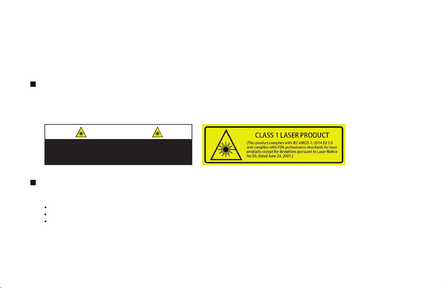
CAUTION
Use of controls or adjustments or performance of
procedures other than those specified herein may result in
hazardous radiation exposure
Laser Safety Notice – Laser Class 1
The device satisfies the requirements of:
IEC 60825-1:2014;
21 CFR 1040.10 and 1040.11 except for deviations pursuant to Laser Notice No.50, dated June 24, 2007;
GB7247.1-2012
DISCLAIMER The information contained within this user’s manual and the functions offered are intended to provide information about
products. All reasonable efforts have been made to ensure the accuracy of the information. However, Hesai cannot be held responsible for
any errors. Hesai does not warrant the accuracy and reserves the right to make changes to the catalog and its functions at any time without
notice.

Contents
Introduction
1
1.1
1.2 Specifications
2
2.1
2.2
2.3
2.4
3
3.1
3.2
4
4.1
4.2
Operational Principles
Installation Guide
Mechanical Installation (Metric System)
Interface
Connecting Box (Optional Component)
Get Ready to Use
LiDAR Data Structure
Point Cloud Data Packet Ethernet Header/UDP Data
GPS Data Packet Ethernet Header/UDP Data
Web Control
Open Web Control
Setting
01-03
04
05-07
08
09-11
12
13-16
17-20
21
22
4.3
4.4
Device Info
Firmware Upgrade
Appendix I
Pandar40 Channel Distribution
Appendix II
Point Cloud Data Packet Absolute Time and
Laser Firing Time Calculations
Appendix III
PandarView
Appendix IV
FCC Statement
Appendix V
Support and Contact
23
24
25-27
28-31
32-39
40
41-42

Introduction1
Pandar40 is a 40-channel mechanical LiDAR. It creates 3D imaging by 360° mechanical rotating through 40 laser diodes inside the housing.
Pandar40’s unique channel distribution makes it more suitable for autonomous driving applications.
In addition to the specifications of Pandar40, this manual also describes the mechanical installation, data outputs format, and GPS
timestamp synchronization.
This manual is undergoing constant revision and improvement, please ask Hesai for the lastest version of the user’s manual.
Operational Principles
1.1
1.1.1 Distance Measurement: Time of Flight (ToF)
A laser diode emits a beam of ultrashort pulse laser on to the object.
1.
Diffuse reflection of the laser occurs upon contact with the target object. Reflected beams are detected by the optical sensor.
2.
Distance to object can be accurately measured by calculating the time between emission and receipt by the sensor.
3.
-01-
1
d= ct
2
d:Distance
c:Speed of light
t:Laser beam travel time
Figure 1.1 ToF Formula
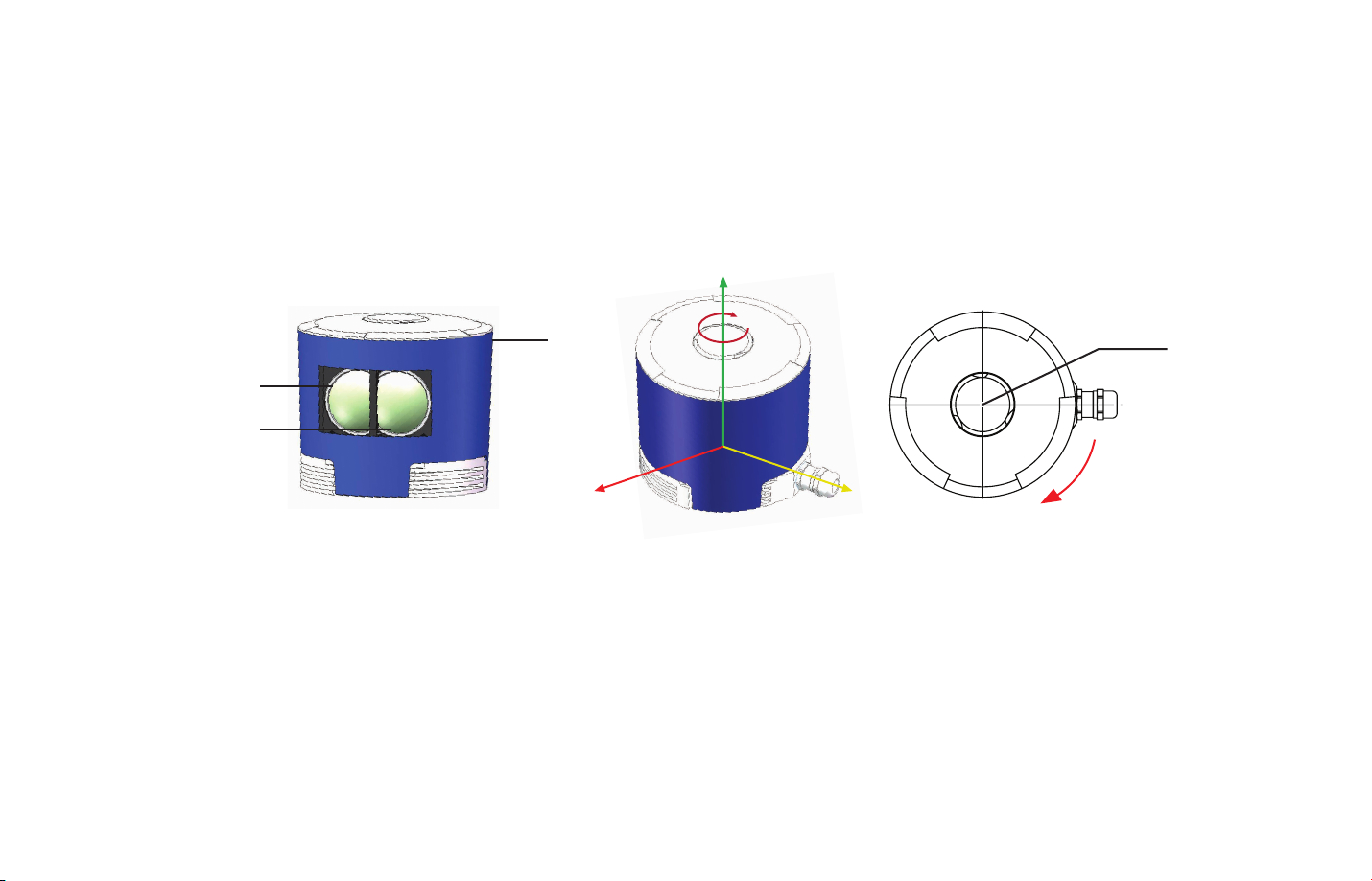
1.1.2 Structure Description
40 pairs of laser emitters and receivers are attached to a rotating motor inside the LiDAR housing that perform horizontal scans in 360
degrees.
Z
270°
Laser Receiver
Laser Emitter
Figure 1.2 Partial Cross-Sectional Diagram
Shell
X Y
Figure 1.3 LiDAR Coordinate System and Rotation Direction
180°
Clockwise Rotation Direction
90°
Reference Center
0°
Cable
NOTE
1) Figure 1.3 shows the coordinate system and the z axis is along the rotation center of the LiDAR. The origin of the coordinate system is
shown as a red dot in Figure 1.5 (side view of the LiDAR). All the LiDAR measurement data are relative to the origin after geometry
transformation according to LiDAR’s optical and mechanical design.
2) Because of the intrinsic angle offset of each laser channel, the zero degree is defined as the azimuth angle in the corresponding block in
UDP packet when channel 12 passes y axis defined in Figure 1.3.
-02-
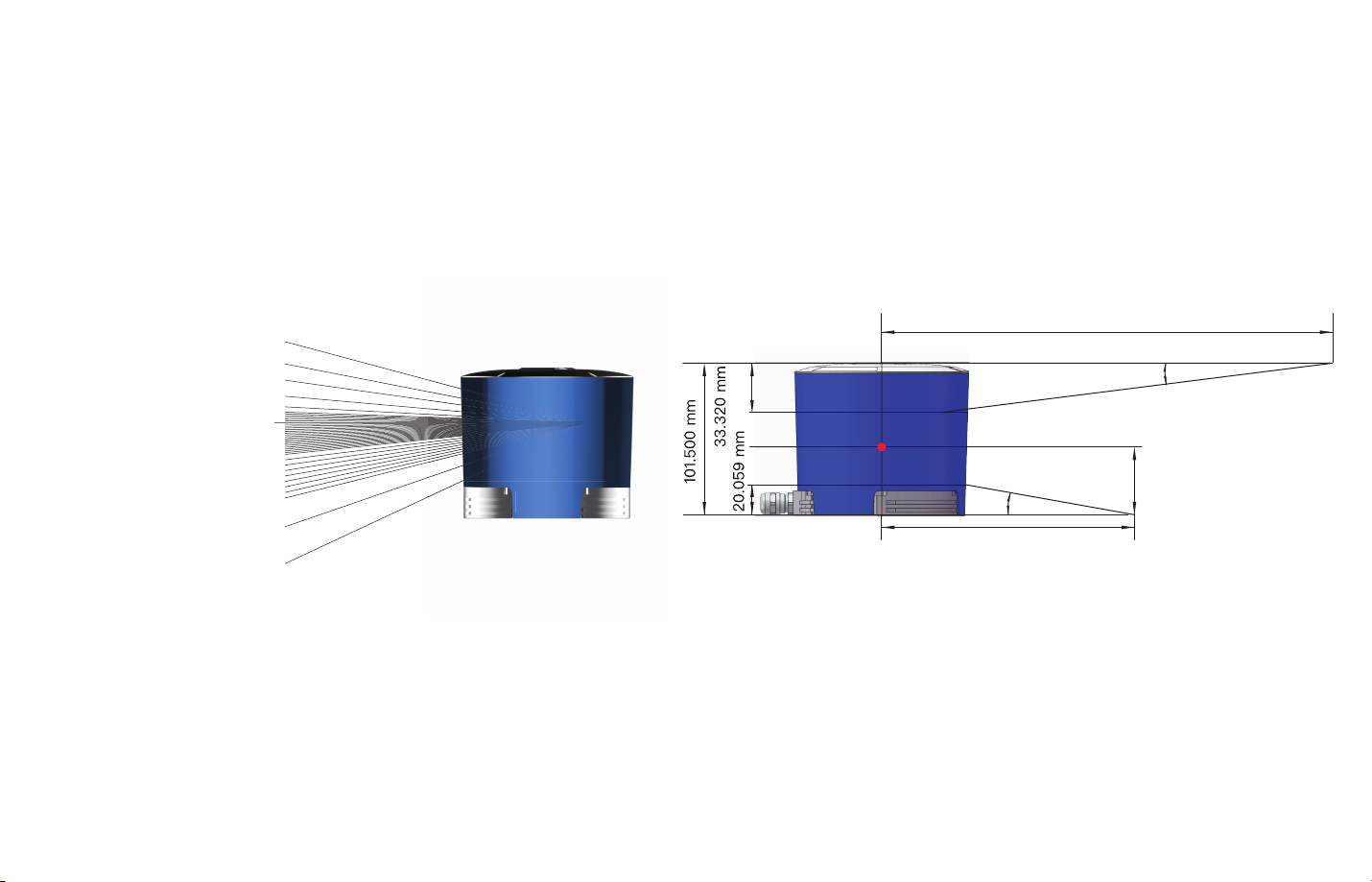
1.1.3 Pandar40 Channel Vertical Distribution
The vertical angular resolution is 0.33° between Channel 6 and Channel 30;
The vertical angular resolution is 1° between Channel 5 and Channel 6, Channel 30 and Channel 38;
The vertical angular resolution of the remaining channels is not evenly distributed.
Please see Appendix I for detailed channel distribution.
-03-
Channel 1
Channel 6
Channel 12
Channel 30
Channel 38 - 14°
Channel 40
+ 15°
+ 2°
0°
- 6°
- 25°
Figure 1.4 Channel Vertical Distribution
181.640 mm
15°
45.400 mm
25°
99.002 mm
Figure 1.5 Laser Firing Position

1.2
Specifications
Scanning Method Mechanical Rotating
Channel 40
Wavelength 905 nm
Laser Class Class 1 Eye Safe
Measurement Range 0.3 m to 200 m (at 20% reflectivity)
Data Points Generated
Frame Rate (Configurable)
Measurement Accuracy
FOV (Horizontal) 360°
Angular Resolution (Horizontal)
FOV (Vertical)
*Specifications are subject to change without notice.
Single Return Mode: 720,000 points per second
Dual Return Mode: 1,440,000 points per second
10 Hz,20 Hz
±5 cm (0.3 m to 0.5 m);
±2 cm (0.5 m to 200 m)
0.2° (10 Hz), 0.4° (20 Hz)
40° (-25° to +15°)
Table 1.1 Specifications of Pandar40
0.33° (-6° to +2°);
1° (+2° to +3°, -14° to -6°);
2° (+3° to +5°);
Angular Resolution (Vertical)
Data Transmission Method UDP/IP Ethernet (100 Mbps)
Operating Voltage 9 V to 48 V
Power Consumption 18 W
Enclosure Level IP67
Operating Temperature -20℃-60℃
Weight 1.46 kg
Dimensions
3° (+5° to +11°);
4° (+11° to +15°);
5° (-19° to -14°);
6° (-25° to -19°)
Height: 101.50 mm;
Top Diameter: 116.00 mm;
Bottom Diameter: 112.00 mm
-04-
2 Installation Guide
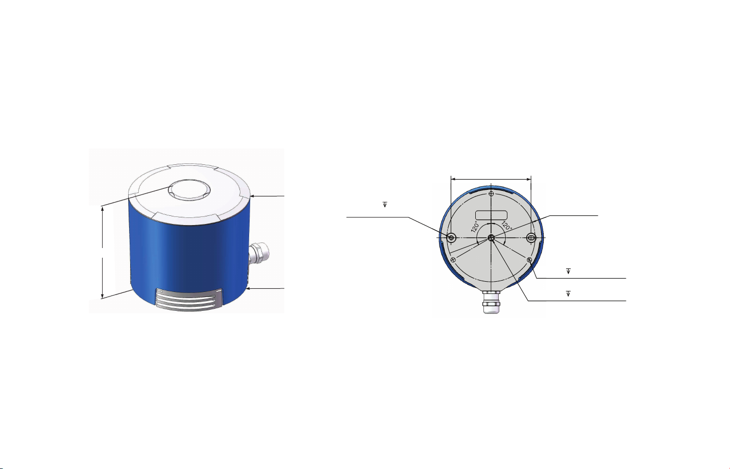
Mechanical Installation(Metric System)2.1
88.90mm
-05-
101.50mm
φ116.00mm
φ112.00mm
Figure 2.1 Pandar40 Side View Figure 2.2 Pandar40 Mounting Base
2×φ4mm 6mm
Forφ4mm PINS
φ98mm
3×M6 6mm(MOUNT)
M6 8mm(MOUNT)

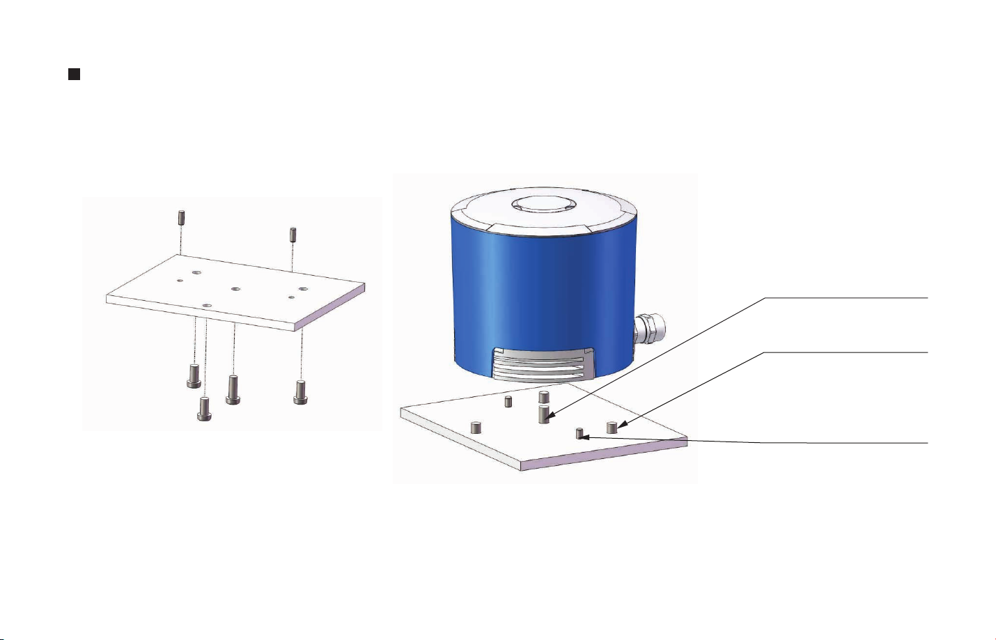
Quick Installation
M6 screw
7~9mm over mounting base
2xΦ4PINS
5~6mm over mounting base
Figure 2.3 Diagram of Quick Installation
-06-
Stable Installation
M6 screw
7~9mm over mounting base
3xM6 screw
5~6mm over mounting base
2xΦ4PINS
5~6mm over mounting base
-07-
Figure 2.4 Diagram of Stable Installation
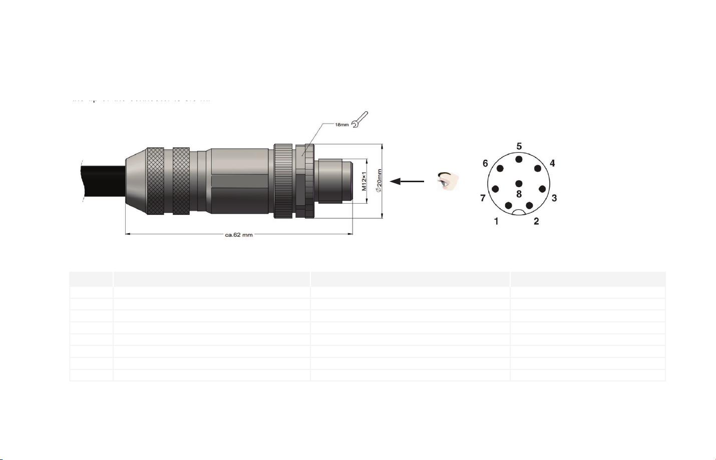
Interface2.2
the tip of the connector is 0.3 m.
Pandar40 uses Phoenix Contact (PN: SACC-M12FS-8CON-PG 9-SH) as the communication connector. The cable length from LiDAR exit to
the tip of the connector is 0.3 m.
Pin #
1
2
3
4
5
6
7
8
B
First View:
The direction from the
eye to the interface as
shown
A
Function Color Voltage (V)
Ethernet RXEthernet RX+
Ethernet TXEthernet TX+
GPS Serial Data
GPS PPS
+12V
Ground (Return)
Table 2.1 Communication Connector Description
Figure 2.5 Phoenix Contact
Blue
Light Blue (Blue/White)
Orange
Light Orange (Orange/White)
White
Yellow
Red
Black
B
-1V to 1V
-1V to 1V
-1V to 1V
-1V to 1V
-13V to +13V
3.3V/5V
Black
12V
-08-
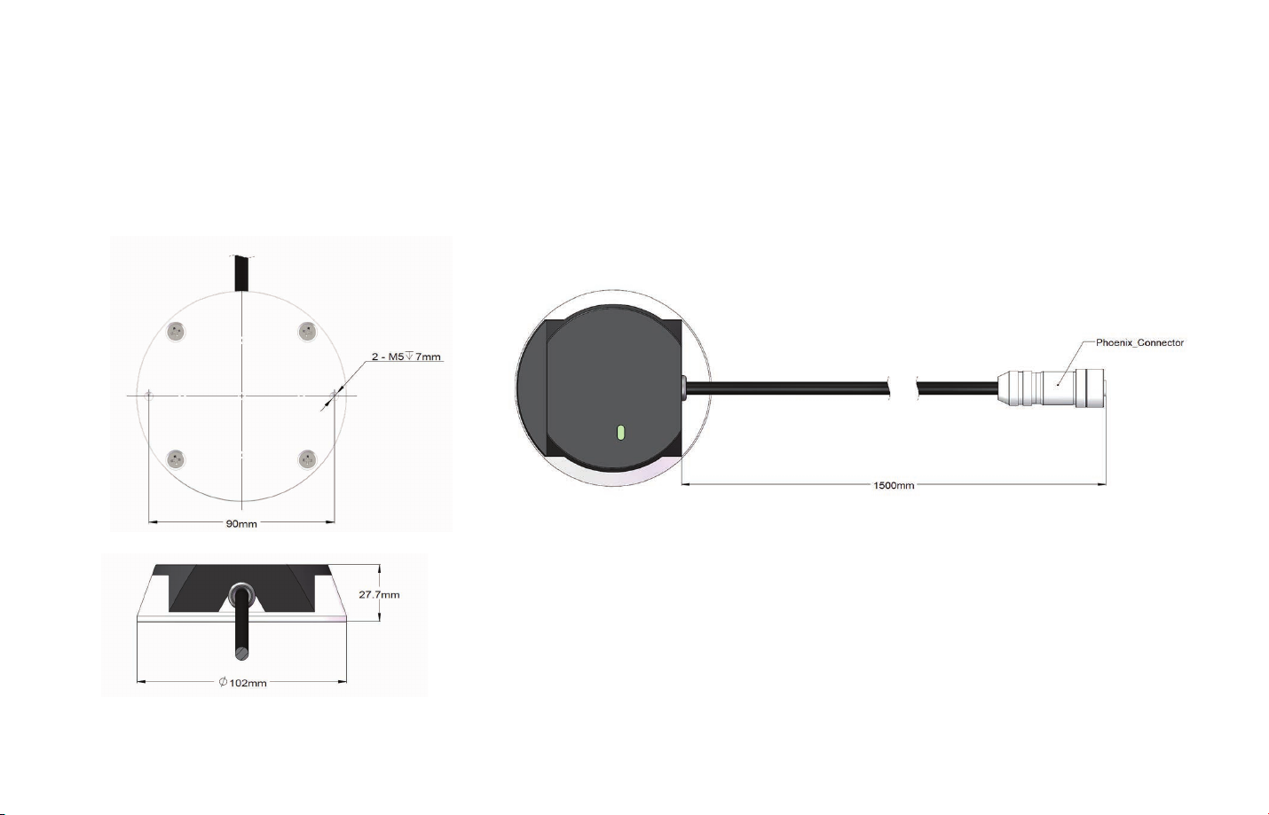
2.3
Connecting Box (Optional Component)
Connecting box is the optional component of Pandar40. Users can choose to connect LiDAR using the connecting box.
The connecting box comes equipped with a power port, a GPS port, and a standard ethernet port. The cable length from
phoenix connector to the connecting box is 1.5 m.
-09-
Figure 2.6 Connecting Box

2.3.1 Connecting Box Interfaces
1 2 3 4 5 6
c
a
b
Figure 2.7 Connecting Box Interfaces
a Standard Ethernet Port
RJ45, 100 Mbps Ethernet
b Power Portb Power Port
Use DC-005 DC power adapter
Input voltage ranges from 9V to 32V
Power consumption is 15W
c GPS Port
Connector type: JST SM06B-SRSS-TB
Recommended connector for external GPS module:
JST SHR-06V-S-B
Voltage standard: RS232
Baud rate: 9600bps
Cable
GPS port pin number from left to right is 1 to 6, and the specific
definition of each pin is shown as follows:
Pin No.
2 Output 5V power, to provide power for external GPS module
3 Output GND, to ground external GPS module
4 Input
5 Output GND, to ground external GPS module
6 Output
Direction Pin Description
1 Input
PPS synchronizing signal, to receive synchronized
pulses from the GPS module TTL 3.3V/5V
Receiving signal of serial port, to receive serial data
from external GPS module, RS232 level
Transmitting signal of serial port, to send serial data
to the external GPS module, RS232 level
Table 2.3 GPS Pin No. DescriptionTable 2.2 Connecting Box Interfaces Description
-10-

2.3.2 How to Connect using Connecting Box
Power port and
standard Ethernet port
Pandar40
Connect the power port to the adapter.
Use an Ethernet cable to connect
the LiDAR’s and computer’s
Ethernet ports.
-11-
Computer Connecting Box
Figure 2.8 How to Connect Using Connecting Box

2.4 Get Ready to Use
Pandar40 begins to scan and transmit data automatically once it is wired and powered up.
To receive the data on your PC, please set the PC IP address to 192.168.1.100 and Subnet mask to 255.255.255.0.
Point cloud data can be quickly viewed or recorded by using PandarView, the point cloud data viewer software developed by Hesai. For more
on PandarView installation and usage, see Appendix III PandarView.
NOTE Pandar40 does not have a power switch. It starts to operate whenever power is applied.
NOTE Web control can be used to set up the configurable parameters of the LiDAR before using. For more on web control functions, see
Chapter 4.
NOTE SDK (Software Development Kit) of our LiDAR can be found on Hesai official Github.
-12-

LiDAR Data Structure3
The communication protocol for data output of Pandar40 is Fast Ethernet UDP/IP. The output data includes point cloud data packet and
GPS data packet. Each data packet consists of an ethernet header and a UDP data.
Ethernet Header: 42 bytes
Point Cloud Data Packet
LiDAR Data
GPS Data Packet
Figure 3.1 LiDAR Data Structure Illustration
UDP Data: 1256 bytes
Ethernet Header: 42 bytes
UDP Data: 512 bytes
3.1 Point Cloud Data Packet Ethernet Header/ UDP Data
Each Pandar40 point cloud data packet has a 42 bytes ethernet header and 1256 bytes UDP data.
-13-
Ranging Data: 1240 bytes
Additional Information: 16 bytes

3.1.1 Point Cloud Data Packet – Ethernet Header
Here is an example of point cloud data packet ethernet header definition:
Ethernet Header: 42 bytes
Ethernet II MAC
Ethernet Data Packet Type
Internet Protocol
UDP Port Number
UDP Length and Checksum
12 bytes
2 bytes
20 bytes
4 bytes
4 bytes
Destination: Broadcast (0xFF: 0xFF: 0xFF: 0xFF: 0xFF: 0xFF), Source: (xx:xx:xx:xx:xx:xx)
0x08, 0x00
Version, Header Length, Differentiated Services, Field, Total Length, Identification, Flags, Fragment Offset,
Time to Live, Protocol, Header Checksum, Source IP Address, Destination IP Address
UDP source port (0x2710, represents 10000), destination port (0x0940, represents 2368)
Length 2 bytes (0x04F0, represents 1264 bytes), checksum 2 bytes (0x00, represents no check)
Table 3.1 Point Cloud Data Packet Ethernet Header Definition
IP Address
The destination IP address is 0xFF FF FF FF and in broadcast form.
The default source IP address is 192.168.1.201.
Taking “Internet Protocol (20 bytes)” as an example,
it is described as Figure 3.2:
Figure 3.2 Point Cloud Data Header Internet Protocol Illustration
-14-

3.1.2 Point Cloud Data Packet- UDP Data
The UDP Data of Pandar40 has a 1256 bytes payload consisting of 1240 bytes ranging data and 16 bytes additional information.
All the multi-byte values are the unsigned type and in Little Endian format.
Block 1 Block 2 Block 3 Block 10
Ranging Data 1240 bytes (10 blocks)
······
-15-
0xFFEE 0xFFEE 0xFFEE 0xFFEE
Azimuth Angle 1 Azimuth Angle 2 Azimuth Angle 3 Azimuth Angle 10
Channel 1 Unit 1 Channel 1 Unit 2 Channel 1 Unit 3 Channel 1 Unit 10
Channel 2 Unit 1 Channel 2 Unit 2 Channel 2 Unit 3 Channel 2 Unit 10
······ ······ ······ ······
Channel 40 Unit 1 Channel 40 Unit 2 Channel 40 Unit 3 Channel 40 Unit 10
Table 3.2 Point Could Data UDP Data-Ranging Data
······
······
······
······
······
······
The definition of each block in ranging data is as follow:
Each Block in
Ranging Data:
124 bytes
0xFFEE 2 bytes
Azimuth Angle 2 bytes
Channel XX Unit XX 3 bytes
Table 3.3 Block Definition
Head, meaningless, 0xFF first
Represents the current reference angle of the rotor
Azimuth [15:0]: lower byte Azimuth_L [7:0] is in the front, upper byte
Azimuth_H [15:8] is in the back
Azimuth Angle=[Azimuth_H, Azimuth_L]/100°=Azimuth/100°
2 bytes distance data
1 byte reflectivity data
Distance Value=Range*4mm
Maximum Distance Value=(2^16–1)*4mm=
262.14m
NOTE Under dual return mode, azimuth angle changes every two blocks. The odd number block is the last return, and the even number block
is the strongest return.

Additional Information: 16 bytes
Reserved 5 bytes reserved data, meaningless
0x01 means high temperature; 0x00 means normal operation
High Temperature
Shutdown Flag
Reserved 2 bytes reserved data, meaningless
Motor Speed 2 bytes speed_2_bytes [15:0] = speed (RPM)
GPS Timestamp 4 bytes
Return Mode Information 1 byte the strongest return (0x37), the last return (0x38), dual return (0x39)
Factory Information 1 byte 0x42 (or 0x43)
1 byte
· during normal operation, shutdown flag keeps being 0x00
· if high temperature is detected and system needs to be shut down, the shutdown flag will be set to 0x01, and the
system will be shut down after 60 seconds. The flag keeps being 0x01 during the 60 seconds and shutdown period
· after the high temperature shutdown, the Lidar temperature will decrease. When the system is not in high
temperature status, the shutdown flag will be reset to 0x00 and the system can return to normal operation
the firing time of the first laser in the first block, the unit is 1 μs, maximum value is 71.58 minutes
Table 3.4 Point Cloud Data UDP Data-Additional Information
Example of UDP Data Analysis
Taking Channel 5 in block 3 of a UDP Data Packet as an example, please see Appendix I for detailed channel distribution:
1) Horizontal angle offset of the laser is -2.50°, and vertical angle of the laser is 3.00° for Channel 5 (refer to Appendix I).
2) Horizontal angle is the current reference angle of the rotor plus horizontal angle offset, so the result is (Azimuth Angle 3+(-2.5)) degree.
(NOTE We define clockwise as a positive direction of the angle from top view)
3) Analyze the “Channel 5 Unit 3” from the UDP Data Packet, and the distance formed by upper 2 bytes multiplied by 4 mm is the actual
distance in millimeters in the real world.
By now, the direction and distance of this point have been decided, and this obstacle point could be drawn in the polar or rectangular
coordinate system. The real-time point cloud data of Pandar40 can be drawn by analyzing every data in the UDP Data Packet using the
above method.
-16-

3.2 GPS Data Packet Ethernet Header/UDP Data
Each GPS Data Packet has a 42 bytes ethernet header and 512 bytes UDP Data. All the multi-byte values are the unsigned type and in Little
Endian format. GPS UDP Data Packet will be triggered if there is GPS PPS signal, and the port is 10000.
3.2.1 GPS Data Packet – Ethernet Header
Ethernet Header: 42 bytes
-17-
Ethernet II MAC 12 bytes
Ethernet Data Packet Type
Internet Protocol
UDP Port Number
UDP Length and Checksum
2 bytes
20 bytes
4 bytes
4 bytes
Destination: Broadcast (0xFF: 0xFF: 0xFF: 0xFF: 0xFF: 0xFF), Source: (xx:xx:xx:xx:xx:xx)
0x08, 0x00
Version, Header Length, Differentiated Services, Field, Total Length, Identification, Flags, Fragment
Offset, Time to Live, Protocol, Header Checksum, Source IP Address, Destination IP Address
UDP source port (0x2710, represents10000), destination port (0x277E, represents 10110)
Length 2 bytes (0x208, represents 520 bytes), checksum 2 bytes (0x00, represents no check)
Table 3.5 GPS Data Packet Ethernet Header Definition
IP Address
The destination IP address is 0xFF FF FF FF and in broadcast form.
The default source IP address is 192.168.1.201.
Taking“Internet Protocol (20 bytes)” as an example,
it is described as Figure 3.3:
Figure 3.3 GPS Data Ethernet Header Internet Protocol Illustration

3.2.2 GPS Data Packet - UDP Data
Every second, one UDP data will be triggered by one GPS PPS. UDP data has 512 bytes, and the port is 10110.
GPS UDP data: 512 bytes
Header
Date
GPS Time Data 18 bytes
GPRMC Data 77 bytes ASCII code, valid till 2 bytes after ‘*’
Reserved Data 411 bytes
Location valid or not 1 byte
Flag of PPS lock 1 byte
Reserved Data 4 bytes
Time
μs Time
Filled with 411 0xDF
From GPRMC information, ASCII code, A=valid, V=invalid
1=locked, 0=unlocked
Reserved meaningless data
2 bytes
6 bytes
6 bytes
4 bytes
0xFFEE, 0xFF first
Year month and day in order (2 bytes each), lower byte first, ASCII code
Second minute and hour in order (2 bytes each), lower byte first, ASCII code
Unit is μs, lower byte first
Table 3.6 GPS Data Packet-UDP Data Definition
-18-

Example of GPS Data Packet UDP Data Analysis
Figure 3.4 GPS Data Packet UDP Data Illustration
Date
Year: 0x37, 0x31, convert ASCII code to '7', '1'; means 17
Month: 0x32, 0x31, convert ASCII code to '2', '1'; means 12
Day: 0x30, 0x32, convert ASCII code to '0', '2'; means 20
Time
Second: 0x32, 0x35, convert ASCII code to '2', '5'; means 52
Minutes: 0x35 0x34 convert ASCII code to '5’, '4; means 45
Hour: 0x32 0x31, convert ASCII code to '2', '1'; means 12 (UTC time)
-19-
μs Time
4 bytes, the μs time value of each GPS PPS pulse, and timestamp will be set as (minute*60+second)*1000000 μs.
The μs time of GPS PPS and the timestamp from the point cloud data have the same data source,and the unit is 1 μs.

GPRMC Data Format
The standard GPRMC data format is as follows:
$GPRMC,<01>,<02>,<03>,<04>,<05>,<06>,<07>,<08>,<09>,<10>,<11>,<12>*hh
Detailed descriptions are as follows:
<01> UTC Time, hhmmss (hour, minute, second) format
<02> Location Status, A=Valid Position, V=Invalid Position
<03> Latitude ddmm.mmmm (degree, minute) format
<04> Latitude Northern (N) or Southern (S) Hemisphere
<05> Longitude dddmm.mmmm (degree, minute) format
<06> Longitude Eastern (E) or Western (W) Hemisphere
The GPS interface of Pandar40 is compatible with a variety of data formats. The external GPS module GPRMC data format needs to meet
the following conditions:
the data in <01> is the hour, minute, and second information; the data in <09> is the date information.
<07> Ground Rate (000.0 to 999.9 knots)
<08> Ground Direction (000.0~359.9 degrees, referencing true north)
<09> UTC Date, ddmmyy (day, month, year) format
<10> Declination (000.0 to 180.0 degrees)
<11> Declination Direction, E (east) or W (west)
<12> Mode (only on version NMEA0183 3.00, A=Automatic
Positioning, D=Differential, E=Estimation, N=Invalid Data)
The following two formats are both admissible:
1) $GPRMC,072242,A,3027.3680,N,11423.6975,E,000.0,316.7,160617,004.1,W*67
2) $GPRMC,065829.00,A,3121.86377,N,12114.68322,E,0.027,,160617,,,A*74
-20-

Web Control4
Web Control can be used to set Pandar40 parameters, check device info, and upgrade.
Before setting, please connect LiDAR and the computer using Ethernet cable. Set IP address to 192.168.1.100.
Open Web Control4.1
After setting, open browser and type URL: 192.168.1.201/index.html to enter the web control homepage.
-21-
Figure 4.1 Home Page of Web Control

Setting4.2
Pandar40 supports both broadcast (default setting) and
1)
unicast.
To use broadcast, please set Destination IP as
255.255.255.255. To use unicast, please set Destination IP as
the same as PC IP address.
Users can choose the dual return type from the last return, the
2)
strongest return, and the dual return.
Users can choose the spinning rate from 600 rpm and 1200
3)
rpm.
Users can choose the GPS sync angle. If set as 0, then the 0
4)
degree angle is in sync with PPS.
Users can choose angle range less than 360° by specifying
5)
start and end angles. There will be no laser firing or data
generated outside the specified angle range. If the start angle
and the end angle are the same, all lasers will only fire at this
particular angle.
Users can configure the rotation direction to clockwise or
6)
anticlockwise. The coordinate system remain the same despite
the choice of rotation direction. Please refer to Figure 1.3 for
more details.
Figure 4.2 Setting Page of Web Control
-22-

Device Info4.3
Software version, hardware version, firmware version can be viewed from device information page.
-23-
Figure 4.3 Device Info Page of Web Control

Firmware Upgrade4.4
Please ask Hesai for the latest upgrade file if needed. Click on “Upload” button to upload the upgrade file. Please reboot the LiDAR after
finishing upgrading.
Figure4.4 Upgrade Page of Web Control
-24-

Appendix I
Pandar40 Channel Distribution
Channel Number of Laser
Channel number in
UDP Data Packet
01 (Top Line)
Horizontal Angle Offset
(Azimuth)
The horizontal angle of each line is
the sum of current reference angle
of the rotor and the angle below.
Define clockwise as positive.
-1.042
Vertical Angle
(Elevation)
The vertical angle of each line
is constant, and 0° represents
horizontal direction. Define
upward as positive.
15.00
Instrument Range
(in meters)
Instrument range
capability
130
Range Capability vs. Reflectivity
(in meters)
Range capability at
objects with specific
reflectivity
200@20%
-25-
02
03
04
05
06
07
08
09
10
11
12 (Horizontal Line)
13
14
-1.042
-1.042
-1.042
-1.042
-1.042
3.125
-5.208
-1.042
3.125
-5.208
-1.042
3.125
-5.208
11.00
8.00
5.00
3.00
2.00
1.67
1.33
1.00
0.67
0.33
0.00
-0.33
-0.67
130
130
130
230
230
230
230
230
230
230
230
230
230
200@20%
200@20%
200@20%
200@20%
200@20%
200@20%
200@20%
200@10%
200@10%
200@10%
200@10%
200@10%
200@10%

Channel Number of Laser
15
Horizontal Angle Offset
(Azimuth)
-1.042
Vertical Angle
(Elevation)
-1.00
Instrument Range
(in meters)
230
Range Capability vs. Reflectivity
(in meters)
200@10%
16
17
18
19
20
21
22
23
24
25
26
27
28
29
30
31
32
33
3.125
-5.208
-1.042
3.125
-5.208
-1.042
3.125
-5.208
-1.042
3.125
-5.208
-1.042
3.125
-5.208 -5.67
-1.042 -6.00
-1.042 -7.00
-1.042
-1.042
-1.33
-1.67
-2.00
-2.33
-2.67
-3.00
-3.33
-3.67
-4.00
-4.33
-4.67
-5.00
-5.33
-8.00
-9.00
230 200@10%
230 200@10%
230 200@10%
230 200@20%
230 200@20%
230 200@20%
230 200@20%
230 200@20%
230 200@20%
230 200@20%
230 200@20%
130 200@20%
130 200@20%
130 200@20%
130 200@20%
130 200@20%
130 200@20%
130 200@20%
-26-

Channel Number of Laser
34
Horizontal Angle Offset
(Azimuth)
-1.042
Vertical Angle
(Elevation)
-10.00
Instrument Range
(in meters)
130
Range Capability vs. Reflectivity
(in meters)
200@20%
35
36
37
38
39
40 (Bottom Line)
-1.042
-1.042
-1.042
-1.042
-1.042
-1.042
-11.00
-12.00
-13.00
-14.00
-19.00
-25.00
Table I.1 Pandar40 Channel Distribution
130 200@20%
130 200@20%
130 200@20%
130 200@20%
130 200@20%
130 200@20%
-27-

Appendix II
Point Cloud Data Packet Absolute Time and Laser Firing Time Calculations
Pandar40 transmits two types of UDP Data Packet, including the point cloud UDP Data Packet and the GPS UDP Data Packet, hereafter
referred to as Point Cloud Data Packet and GPS Data Packet.
1 Absolute Time Calculation of Point Cloud Data Packet
LiDAR transmits a GPS Data Packet and a Point Cloud Data Packet chronologically with μs timestamps from the same data source. The μs
timestamp in the Point Cloud Data Packet (GPS Timestamp) is used to calculate the packing time of this data packet.
There are two methods to calculate the absolute packing time of Point Cloud Data:
1) Retrieve the μs timestamp and the time information (UTC, decimal number) from the Point Cloud Data Packet. The absolute time of Point
Cloud Data Packet can be calculated by combining 2 parts: a) the 4 bytes μs timestamp; b) the 6 bytes UTC time information (decimal
number) in Point Cloud Data Packet.
2) First retrieve timestamp from the Point Cloud Data Packet, then retrieve time information (UTC) from the previous GPS Data Packet. The
absolute time of Point Cloud Data Packet can be calculated by combining 2 parts: a) the 4 bytes μs timestamp; b) the UTC time information
(decimal number) in previous GPS Data Packet.
NOTE
1) Because LiDAR GPS Data Packet is triggered by PPS rising edge, the corresponding GPRMC information (real absolute time) from GPS
module after PPS rising edge is not available at that time.
2) The UTC time in LiDAR GPS Data Packet and following Point Cloud Data Packet can only utilize previous GPRMC information, which is 1
full second older than the absolute time of the triggering PPS rising edge. But the LiDAR can automatically adjust and the user can simply
add the 4 bytes timestamp and 6 bytes UTC time to get absolute time.
3) Since every GPS Data Packet matches an internal 1Hz signal, the GPS Data Packet will be exported continuously in every second with or
without GPRMC information. If GPRMC is available, UTC time in data packets are updated according to GPRMC and avoid drift of internal
1Hz signal; if GPRMC is not available, UTC time in data packets are updated according to internal 1Hz signal and keep the mechanism.
NOTE Please refer to Appendix III for the calculation of absolute time using PTP protocol.
-28-

2 Laser Firing Time Calculation
The laser firing time of every laser channel can be calculated by using the absolute time in Point Cloud Data Packet.
Assuming the Point Cloud Data Packet's absolute time is t0.
Ranging Data 1240 bytes (10 blocks)
Block 1 Block 2 Block 3 Block 10
0xFFEE 0xFFEE 0xFFEE 0xFFEE
Azimuth Angle 1 Azimuth Angle 2 Azimuth Angle 3 Azimuth Angle 10
Channel 1 Unit 1 Channel 1 Unit 2 Channel 1 Unit 3 Channel 1 Unit 10
Channel 2 Unit 1 Channel 2 Unit 2 Channel 2 Unit 3 Channel 2 Unit 10
······ ······ ······ ······
Channel 40 Unit 1 Channel 40 Unit 2 Channel 40 Unit 3 Channel 40 Unit 10
Table II.1 Point Could Data UDP Data-Ranging Data
······
······
······
······
······
······
······
Single Return Mode
There are 10 Blocks in every Point Cloud UDP Data Packet.
In the single return mode, each block consists of 40 laser channels ranging data. The end time of the Block means all the 40 channels laser
finished the firing.
The calculation of each Block's end time is as follows:
End time of Block10: (t0-28.58) μs;
01)
End time of BlockN: (t0-28.58-55.56*(10-N)) μs;
02)
End time of Block3: (t0-28.58-55.56*7) μs;
03)
End time of Block2: (t0-28.58-55.56*8) μs;
04)
End time of Block1: (t0-28.58-55.56*9) μs.
05)
-29-

Dual Return Mode
There are 10 Blocks in every Point Cloud UDP Data Packet.
In the dual return mode, Block (1, 2) are corresponding to dual return ranging data for the same 40 channels laser firing, so they have
the same firing time for each laser and the same end time for the Block. Similarly, Block (3, 4) and so on have same firing and end time.
The calculation of each Block's end time is as follows:
01)
End time of Block10: (t0-28.58) μs;
02)
End time of Block9: (t0-28.58) μs;
03)
End time of Block8: (t0-28.58-55.56*1) μs;
04)
End time of Block7: (t0-28.58-55.56*1) μs;
05)
End time of Block6: (t0-28.58-55.56*2) μs;
Through the Block's end time, it is possible to calculate the laser firing time for every channel in the Block.
Take Block 6 for example, assuming Block 6's end time is t6, then:
01)
Laser ID 4’s firing time: (t6-3.62) μs;
02)
Laser ID 40’s firing time: (t6-3.62) μs;
03)
Laser ID 36’s firing time: (t6-4.92) μs;
04)
Laser ID 28’s firing time: (t6-6.23) μs;
05)
Laser ID 12’s firing time: (t6-8.19) μs;
06)
Laser ID 16’s firing time: (t6-8.19) μs;
07)
Laser ID 32’s firing time: (t6-9.5) μs;
08)
Laser ID 24’s firing time: (t6-11.47) μs;
09)
Laser ID 29’s firing time: (t6-12.77) μs;
10)
Laser ID 17’s firing time: (t6-14.74) μs;
End time of Block5: (t0-28.58-55.56*2) μs;
06)
End time of Block4: (t0-28.58-55.56*3) μs;
07)
End time of Block3: (t0-28.58-55.56*3) μs;
08)
End time of Block2: (t0-28.58-55.56*4) μs;
09)
End time of Block1: (t0-28.58-55.56*4) μs;
10)
11)
Laser ID 3’s firing time: (t6-16.04) μs;
12)
Laser ID 39’s firing time: (t6-16.04) μs;
13)
Laser ID 35’s firing time: (t6-17.35) μs;
14)
Laser ID 25’s firing time: (t6-18.65) μs;
15)
Laser ID 9’s firing time: (t6-20.62) μs;
16)
Laser ID 13’s firing time: (t6-20.62) μs;
17)
Laser ID 31’s firing time: (t6-21.92) μs;
18)
Laser ID 21’s firing time: (t6-23.89) μs;
19)
Laser ID 26’s firing time: (t6-25.19) μs;
20)
Laser ID 14’s firing time: (t6-27.16) μs;
-30-

21)
Laser ID 2’s firing time: (t6-28.47) μs;
22)
Laser ID 38’s firing time: (t6-28.47) μs;
23)
Laser ID 34’s firing time: (t6-29.77) μs;
24)
Laser ID 6’s firing time: (t6-31.74) μs;
25)
Laser ID 22’s firing time: (t6-31.74) μs;
26)
Laser ID 10’s firing time: (t6-33.71) μs;
27)
Laser ID 30’s firing time: (t6-35.01) μs;
28)
Laser ID 18’s firing time: (t6-36.98) μs;
29)
Laser ID 23’s firing time: (t6-38.95) μs;
30)
Laser ID 11’s firing time: (t6-40.91) μs;
31)
Laser ID 1’s firing time: (t6-42.22) μs;
32)
Laser ID 37’s firing time: (t6-42.22) μs;
33)
Laser ID 33’s firing time: (t6-43.52) μs;
34)
Laser ID 5’s firing time: (t6-45.49) μs;
35)
Laser ID 19’s firing time: (t6-45.49) μs;
36)
Laser ID 7’s firing time: (t6-47.46) μs;
37)
Laser ID 27’s firing time: (t6-48.76) μs;
38)
Laser ID 15’s firing time: (t6-50.73) μs;
39)
Laser ID 20’s firing time: (t6-52.7) μs;
40)
Laser ID 8’s firing time: (t6-54.67) μs;
-31-

Appendix III
PandarView
PandarView is a software that is used to play and record the point cloud data. Installations are available on platforms: Windows 7x64/
Windows 8x64/Windows 10x64/Ubuntu-16.04. The installation package can be found in the provided USB disk in the LiDAR box.
1 PandarView Installation
Please install the PandarView and set the computer static IP address to 192.168. 1.100 before running.
Installation
Installation FilesSystem
1.
Windows
Ubuntu-16.04
Double-click on python_2.7.13
2.
Double-click on PandarView_v1.5.5_Windows (install with default settings)
1.
Enter the following command at the terminal:
sudo apt-get install qt4-default libboost-all-dev.
2.
Unzip the installation file
3.
Run PandarView_Installer.bin
Table VI.1 PandarView Installation Steps
IP Configuration
Ubuntu-16.04:
The IP address can be configured on the terminal by using the
ifconfig command:
~$ sudo ifconfig enp0s20f0u2 192.168.1.100
Replace enp0s20f0u2 with the local network port name.
Installation Steps Finish Installation
Pandar.exe shortcut will
show on the desktop after
installation:
Windows:
① Open the Network Sharing Center, click on “Ethernet”.
② In the “Ethernet Status” interface, click on “Properties” to proceed
to the next interface.
③ Double-click on “Internet Protocol Version 4 (TCP/IPv4)”.
④ Configure the IP address to 192.168.1.100 and the subnet mask to
255.255.255.0, then click “OK” to finish configuration.
-32-

2 PandarView Instructions
Check Live Data
Run PandarView, click on and select your LiDAR
model to begin receiving data over Ethernet.
Windows:Double-click shortcut "Pandar" and you
will see an initial interface.
Ubuntu-16.04: Double-click the shortcut on the
desktop (if you set "Run executable text files when they
are opened"), or open the terminal, enter:
~/Desktop/PandarView to open the software.
Record Pcap Files
In real-time play mode, click on the icon to pop up the
"Choose Output File" window. Click on “Save” to begin
recording a pcap file.
After recording, click on again to stop recording the pcap
file.
-33-
Figure III.2 Select LiDAR Model Figure III.3 Choose Output File Window

Play Pcap Files
Click on the icon to open the "Choose Open File" window.
Select the pcap file and click on the icon .
Figure III.4 Choose Open File Window
Import Correction File
Each LiDAR comes with a correction file (CSV) in the provided USB disk.
In the play mode, click on “File” in the upper left corner. Choose “Import Correction File” in the
drop-down menu, select and open the correction file to display the calibrated point cloud.
Click on to play the pcap file and visualize point cloud
data.
Figure III.5 Ready to Play the Pcap File
Figure III.6 File Menu
-34-

Play Buttons
Button Description
Jump to beginning of the file.
While paused, click to view point cloud data from previous frame.
1.
While playing, rewind (click again for different speeds,
2.
such as 2x, 3x, 1/2x, 1/4x, 1x speeds).
1.
After the point cloud file has finished loading, click on to play.
2.
While playing, click on to pause.
While paused, click to view point cloud data in next frame.
1.
While playing, forward (click again for different speeds,
2.
such as 2x, 3x, 1/2x, 1/4x, 1x speeds).
Jump to end of the file.
While playing pcap file, the recording button will be gray and unclickable.
-35-
While playing pcap file, click on this button to loop playback, else playback will stop at the end of file.
Progress bar: drag to control playback speed, or enter frame number to jump to the desired frame.
Table III.2 Play Buttons Description

3 PandarView Features
again to
View Direction Selection
Click on the following buttons to view the point cloud data
from different directions.
Right POV
Figure III.7 View Direction Selection
Mouse Shortcuts
Up
Down
Scroll
01.
Slide scroll wheel to magnify/minimize
02.
Drag while holding left button to adjust view angle
03.
Drag while holding scroll wheel to pan
Front POV Top POV
Hold left button Hold scroll
Figure III.8 Mouse Shortcuts
3D Projection Mode Switching
PandarView enables switching between two types of 3D projection
methods (Orthogonal Projection and Perspective Projection)
through the drop-down menu.
In Orthogonal Projection view, click on ,
thereafter while holding “Control” on the keyboard, select
a point and hold down the left mouse button in order to create a
spatial distance reference, in units of meters. Click on again to
cancel the distance reference.
Distance Reference Circle
Click on to show/hide 12
gray distance reference circles.
The corresponding actual
distances are as shown above.
The lower left axis shows the
current viewing position.
Click “Tools” to open “Grid
Properties”, where you can
change the color and width of
the circles.
Figure III.9 Distance Reference Circle
-36-

Point Cloud Data Selection
Users can click on to display or hide point cloud data from
any selected laser channels. Clicking on this icon will pop up the
following interface. Click on again to close the interface.
Figure III.10 Channel Display Figure III.11 Detailed Data of Selected Point Cloud
Click on the left-side checkboxes to show/hide any given
channel’s display. Check the “Enable/Disable all” option in the
bottom left corner to show/hide all channels at once.
Click on to select visible points. Users can hold down the left
button to box a certain area for selection. The selected points will
be highlighted. Click on to view detailed data of the selected
point cloud. Click on again, select an area outside of the point
cloud data to deselect.
The main data shown about the points are their id, x, y and z values,
angle, distance, reflectivity, corresponding channel id and timestamp
(μs) information.
-37-

Click to compensate the azimuth error caused by the delay of laser activation.
Color Schemes
By clicking on , users can see the current color scheme in the
lower right corner. The drop-down list is used to choose
different color schemes. The default color scheme of point cloud
is drawing according to the intensity. Users can choose azimuth,
distance, laser_id, or timestamp as the color scheme as well.
Figure III.12 Current Color Scheme Figure III.13 Color Editor
Click on to open “Color Editor”,
where users can customize colors.
Click the button again to close the
color editor.
-38-

PandarView Software Version
Click “About” in the upper left corner to check the software version.
Figure III.14 PandarView Softeware Version
-39-

Appendix IV
FCC Statement
FCC ID: 2ASO2PANDAR
This device complies with part 15 of the FCC Rules. Operation is subject to the following two conditions: (1) this device may not cause
harmful interference, and (2) this device must accept any interference received, including interference that may cause undesired operation.
This equipment has been tested and found to comply with the limits for a Class A digital device, pursuant to part 15 of the FCC Rules. These
limits are designed to provide reasonable protection against harmful interference when the equipment is operated in a commercial
environment. This equipment generates, uses, and can radiate radio frequency energy and, if not installed and used in accordance with the
instruction manual, may cause harmful interference to radio communications. Operation of this equipment in a residential area is likely to
cause harmful interference in which case the user will be required to correct the interference at his own expense.
NOTE Any changes or modifications not expressly approved by the grantee of this device could void the user's authority to operate the
equipment.
-40-

Appendix V
Support and Contact
Technical Support
If you have any problems, and cannot find the solution in this manual please contact us:
E-mail: service@hesaitech.com
Website: www.hesaitech.com
GitHub: https://github.com/HesaiTechnology
NOTE If you have any questions about the open source we provide on GitHub, please leave your questions under corresponding projects.
Warranty and Maintenance
If any defect due to faulty software and/or hardware occurs within the warranty period, Hesai Photonics Technology Co., Ltd will provide free
maintenance service. Some operations will violate the warranty, including but not limited to the following:
1) The purchase documents have been altered in any way, made illegible or lost.
2) The defect is caused by abuse or misuse of the product or by environmental conditions that are not in conformance with the
recommended operating condition of the product.
3) Repairs or product modifications, alterations and disassemble have been carried out by unauthorized personals.
4) The unit was stolen, lost or discarded.
5) The damage to the unit is caused by the event of force majeure, including but not limited: abnormal voltage, water or fire, natural disaster
or transport accident.
-41-

Legal Notice
All texts, graphics, and pictures in this manual are subject to the copyright of Shanghai Hesai Photonics Technology Co., Ltd and are
potentially protected by copyright through third parties. No part of the manual may be reproduced, processed, duplicated or published in any
form by photocopying, reprinting or other process, without a written agreement. Despite careful examination, we cannot assume any liability
for the accuracy and legality of the contents published in the manual.
The Customer is not permitted, except as expressly permitted by this Agreement and save to the extent and in the circumstances expressly
required to be permitted by law, to rent, lease, sub-license, loan, copy, modify, adapt, merge, translate, reverse engineer, decompile,
disassemble or create derivative works based on the whole or any part of the Software or its associated documentation or use, reproduce or
deal in the Software or any part of it in any way.
Limitation of Liability
The contents of user's manual are provided “as is” and without warranties of any kind, either express or implied. To the fullest extent
permissible pursuant to applicable law, Hesai Photonics Technology Co., Ltd disclaims all warranties, express or implied, including but not
limited to, warranties of merchantability or fitness for a particular purpose.
In no event shall Hesai Photonics Technology Co., Ltd be liable for any direct, indirect, special, punitive, incidental, exemplary or
consequential, damages, or any damages.
To the extent permissible pursuant to applicable law, the maximum liability of Hesai Photonics Technology Co., Ltd to you shall not exceed
the amount paid by you for the products or services you have ordered.
-42-

Hesai Photonics Technology Co., Ltd
Phone:021-80394947-802
Technical Support:021-80394947-915
Website:www.hesaitech.com
Business Email:info@hesaitech.com
Service Email:service@hesaitech.com
Address:Building L2, Hongqiao World Centre, Shanghai
HESAI WeChat
 Loading...