

HS4000
Handheld Remote
Methane Leak Detector
User’s Manual
www.hesaitech.com
4000-en-1901A1
HESAI Wechat

Notice
Please read this manual carefully before using the equipment.
Caution
To avoid violating the warranty and to minimize the chances of getting electrically shocked, please do not disassemble the device on your
own accord. The device must not be tampered with and must not be changed in any way. There are no user-serviceable parts inside the
device. For repairs and maintenance inquiries, please contact an authorized Hesai Technologies service personnel.
Disclaimer
The information contained within this user's manual and the functions offered are intended to provide information about the product.
All reasonable efforts have been made to ensure the accuracy of the information. However, Hesai cannot be held responsible for any
errors. Hesai does not warrant the accuracy and reserves the right to make changes to the catalog and its functions at any time
without notice.

Contents
Safety Notice
1
1.1
1.2 Laser Safety
1.3 Battery and Charge Safety
1.4 Usage Safety
1.5 Storage and Transportation Safety
1.6 Intrinsic Safety
2
2.1 Working Principle
2.2 Specifications
2.3 Package Components
3
3.1 Buttons
3.2 Light Instructions and Display
3.3 Setting Menus
Body Safety
Introduction
Interface Operation
01
01-02
02
03
03
03
04
05
06
07
08-09
10
4
4.1 Charging Battery
4.2 Battery Installation
4.3 Instructions on the Red Dot Sight
4.4 Bluetooth Connection
4.5 Operational Steps
4.6 Detection Do's and Don'ts
5
Instrument Operation
Technical Support and
Maintenance
5.1 Error Messages
5.2 Trouble Shooting
5.3 Warranty and Maintenance
Appendix I
FCC Statement
11-12
13-14
15
16
17-18
19-20
21
22
23
24

Safety Notice1
Prior to using this product, please read the safety notices carefully to ensure the safety and to avoid any improper usage.
Body Safety
1.1
Do not use the instrument if the outer body is broken or wet.
1)
Please stop using the instrument instantly and pull out the battery in case of smoke, strange smell, short, or fire.
2)
The enclosure level of the instrument is IP54. Please stop using the instrument and pull out the battery if any liquids have gotten inside.
3)
Do not look at laser apertures while using the instrument.
4)
Do not fix the instrument without the permission from Hesai.
5)
Do not touch the LCD when it is broken.
6)
NOTE
Any damage of anodizing layer of the heat sink of middle shell or sight base occurs, the product should be no longer used in hazardous
1)
area.
The instrument satisfies the requirements of:
2)
IEC 60079-0:2017
IEC 60079-11:2011
IEC 60079-28:2015
FCC ID: 2ASO2HS4000
-01-
This device complies with part 15 of the FCC Rules. Operation is subject to the following two conditions: (1) This device may not cause
harmful interference, and (2) this device must accept any interference received, including interference that may cause undesired operation.
The device contains FCC ID:A8TBM71S2.
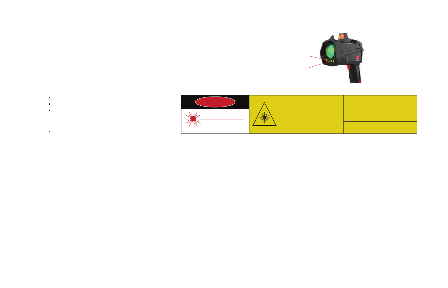
1.2
Laser Safety
Infrared Measurement Laser: Class 1 Eye Safe, wavelength: 1651 nm, <10 mW.
Green Indication Laser: Class 3R, wavelength: 520 nm, <5 mW.
NOTE Please avoid direct eye exposure.
The device satisfies the requirements of:
IEC 60825-1:2014;
IEC 60825-1:2007;
21 CFR 1040.10 and 1040.11 except
for deviations pursuant to Laser
Notice No.50, dated June 24, 2007;
GB7247.1-2012.
1.3 Battery and Charger Safety
Do not use the non-original batteries and chargers.
1)
Do not charge the battery if the charger or the battery is broken.
2)
Please keep surrounding environments safe when charging.
3)
Please keep the charger and battery clean to avoid short.
4)
Please stop charging instantly and unplug the plug when there is short, fire, strange smell, or smoke.
5)
Do not dismantle, modify or repair the battery.
6)
Please store the battery in a cool and dry environment. Do not place the battery in a place with too high or too low temperature.
7)
Do not store or transport the battery together with metal objects.
8)
Do not touch the battery with wet hands.
9)
Do not hit or throw the battery.
10)
If the battery leaks contact with the skin or clothes, be sure to rinse with clean water. Please seek medical attention if necessary.
11)
Do not store the device with the battery installed when not using the device for a long time.
12)
DANGER
LASER RADIATIONAVOID DIRECT EYE EXPOSURE
MAXIMUM OUTPUT: 5 mW
WAVELENGTH: 520 nm
CLASS IIIa LASER PRODUCT
Infrared measurement
laser aperture
Green indication laser
aperture
CLASS 3R LASER PRODUCT AVOID DIRECT EYE EXPOSURE
(This product complies with IEC 60825-1:2014
Ed 3.0 and complies with FDA performance
standards for laser products except for
deviations pursuant to Laser Notice No.50,
dated June 24, 2007.)
MAXIMUM OUTPUT - < 5 mW
OPERATION MODE - CM
WAVELENGTH - 520 nm
IEC 60825-1:2014 CLASS 3R LASER PRODUCT
-02-

Do not change the battery in explosive atmospheres.
13)
Use charger type HS4000-C only.
14)
Do not charge the battery pack in explosive atmospheres.
15)
Do not dispose of the battery pack in the fire.
16)
Never attempt to disassemble the battery pack.
17)
Do not short-circuit the terminals of the battery pack.
18)
Do not take off the battery package in explosive atmosphere.
19)
1.4
1.5
1.6
-03-
Usage Safety
Operating Temperature: -20 to +45℃; Operating Humidity: <80%RH, Non-condensing.
Please avoid electromagnetic interference when using the product.
1)
Do not forcefully push the buttons or subject the device to strong shocks.
2)
Please use the strap when using the device to avoid breakage and foot injury caused by dropping of the device.
3)
Storage and Transportation Safety
Please store the product in a cool and dry environment.
1)
Please transport the product with a dedicated case to avoid strong shocks or vibration.
2)
Intrinsic Safety
Type of Protection: Ex ib op is IIA T3 Gb
II 2 G Ex ib op is IIA T3 Gb
IECEx Certificate Number: IECEx NEP 19.0004X.
ATEX Certificate Number: Baseefa19ATEX0021X.
Introduction2
HS4000 is an ultralight and highly sensitive instrument that utilizes infrared laser to remotely detect methane leaks. HS4000 comes with
Bluetooth capability that can transfer measurement data in real-time to the dedicated APP. Users can use the APP to check, record and
export the data. Through the APP, users can generate detection reports using the saved data as well.
2.1
Working Principle
HS4000 emits an infrared laser at 1.65 um. The laser beam travels to the target, is partially absorbed by the gas, then reflected all the way
back into the receiver.
The reflected laser is collected and converted to an electrical signal that carries information needed to deduce the relative methane concentration.
The reading is expressed by a methane column density (ppm*m). It is the integral of the methane concentration (ppm) and the distance (m)
on the optical path.
Detector
Optical Signal
Converted to
Electrical Signal
Lens
Figure 2.1 Working Principle
Methane Leakage
PipelineInfrared Laser Emitter
-04-

2.2
Specifications
Target Gas
Working Principle
Measurement Method
Sensitivity
Detection Range (CH4)
Measurement Accuracy
Detection Distance
Unit
Response Time
Weight (with battery and sight)
Size (without sight)
Data Transmission
Display
Enclosure Level
Methane (CH4) and
methane-containing gases
Tunable Diode Laser Absorption
Spectroscopy (TDLAS)
Laser Reflection
5 (Actual) ppm*m
0 to 99999 ppm*m
±10% (100 to 50000 ppm*m)
160 m (75% reflectivity, slow
detection mode)
ppm*m/%vol*m/%LEL*m
0.1 s/0.4 s/1.6 s
0.76 kg
160 mm*210 mm*80 mm
Bluetooth, Dedicated APP
2.8 Inch LCD
IP54
Explosion Proof Classification
Laser Classes
Operating Temperature
Operating Humidity
Storage Temperature -20 to +60℃
Sight Effective Distance
Beam Dimension
Power Supply
Operating Time
Self-Test
Threshold Alarm
System False Alarm
Ex ib op is IIA T3 Gb
II 2 G Ex ib op is IIA T3 Gb
Infrared Laser: Class I Eye Safe
Green Indication Laser: Class 3R,
Avoid direct eye exposure
-20 to +45℃
<80%RH, Non-condensing
>15 m
Divergence angle: 2 mrad(4 cm at 20 m)
Rechargeable Lithium battery pack,
Nominal Voltage: 7.2 V, HS4000-B
Continuous operating time: 15 hours
(Typical value, ambient temperature 25°C,
2 batteries)
Built-in self-test while turning on the
instrument, 10 s (typical value)
Threshold: Can be set by users
Alarm: Buzz with LCD turning red
Corresponding error message while there is
any hardware issue
-05-
Table 2.1 Main Specifications
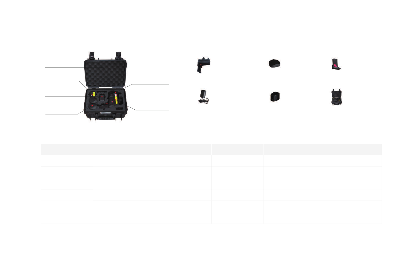
2.3
Package Components
06
05
04
03
No.
01
02
03
04
05
06
02
01
Components
Handheld Remote Methane Leak Detector
Lens Cap
Battery Pack (HS4000-B)
Power Adapter
Charging Base (HS4000-C)
Carrying Case
01
Handheld Remote
Methane Leak
Detector
04
Power Adapter
Figure 2.2 Package Components
Quantity
1
1
2
1
1
1
02
Lens Cap
05
Charging Base
Remark
-
-
Can be equipped with additional batteries
-
-
-
03
Battery Pack
06
Carrying Case
Table 2.2 Package Components Description
-06-

Interface Operation3
3.1
Buttons
No.
01
02
03
04
05
06
01
04
Button
Power/Return Button
Enter Button
Up Button
Down Button
Test Button
Battery Compartment Button
03
02
05
06
Figure 3.1 Device Buttons
Descriptions
Hold the power button about 3 seconds to open the device
Enter the menu/Confirm
Move up the cursor
Move down the cursor
Click once to start testing and click again to stop testing
Used to remove the battery
-07-
Table 3.1 Device Buttons Description

3.2
Light Instructions and Display
3.2.1 Light Instructions
d
a b c
Figure 3.2 Light Instructions
No.
a
b
c
d
Name
Infrared Laser Emitter
Indication Laser (Green)
Working Light (Blue)
Receiving Lens
Notes
-
Class 3R, Avoid Direct Eye Exposure
The indication light will start to blink when the device starts detecting
The blue working light will turn on in the process of device self-test
It will not light after the device is started
-
Table 3.2 Light Instructions
-08-

3.2.2 Interface Display
Bluetooth
Alarm Volume (Configurable)
Unit (ppm*m/%vol*m/%LEL*m)
Maximum Value Detected
Alarm Threshold (Configurable)
Light Intensity (Reflected Light)
Figure 3.3 User Interface
Measuring Speed (Fast, Medium, Slow)
Battery Percentage
Measured Value
Background Value (Configurable)
Histogram of Measured Value (the latest
measured values of the last 80 measurements,
x-axis represents time, y-axis represents
concentration)
NOTE Please measure when the light intensity signal is between 4 to 10 grids to avoid the measurement error caused by too weak or too
strong light intensity.
-09-

3.3
Setting Menus
3.3.1 Menus and Default Settings
Please click the enter button to enter the menus. Through the setting menus, users can set the alarm threshold value, alarm volume,
screen display brightness, screen standby time, and system language. Also, Users can check the device hardware and software version
through About menu.
Figure 3.4 Menus
3.3.2 Changing Settings
Use Up/Down button to select the item or adjust the value.
Use Enter button to enter the submenu or confirm the setting.
Name
Alarm Threshold
Offset
Unit
Measuring Speed
Alarm Volume
Brightness
Power Save
Language
About
Default Setting
200 ppm*m
0 ppm*m
ppm*m (Options: ppm*m/%vol*m/%LEL*m)
Fast (Options: Fast 0.1 s; Medium 0.4 s; Slow 1.6 s)
ON, volume 100% (Options: ON/OFF)
100%
3 Min (Options: 3 Min/10 Min/30 Min/60 Min/120 Min/Never)
English (Options: Chinese/English/French/Spanish)
Hardware Version; Firmware Version; Device Serial NO; Bluetooth Address
Table 3.3 Menu Default Settings
Use Power button to return.
-10-

Instrument Operation4
Before the operation, please read all instructions carefully in this manual.
4.1
Charging Battery
4.1.1 Charging Method
Connect the power adapter cord to the charging base.
1)
Insert the battery into the charging base.
2)
Plug the power adapter into a power outlet.
3)
Unplug the adapter and remove the battery when charging is complete.
4)
Before
After
Figure 4.1 Charging Diagram
-11-

4.1.2 Charging Notes
There are two lights on the battery charging base. One is the fault indicator light, the other is the charging indicator light.
1)
If the fault indicator light is on, stop charging immediately, unplug the charger, and contact us for maintenance.
2)
The charging indicator lights up during charging and turns off when the battery is fully charged.
3)
When the adapter is plugged in but the battery is missing from the charging base, the charge indicator light will blink.
4)
Fault Indicator Light Charging Indicator Light
Figure 4.2 Charging Indicator Light
-12-

4.2
Battery Installation
4.2.1 Insert Battery
-13-
Align the battery with the battery compartment
Step1
NOTE Please ensure surrounding environments are safe.
Push the battery in gently
Step2
Figure 4.3 Insert Battery Steps
The installation is completed when you
Step3
hear a click sound

4.2.2 Remove Battery
Press the battery compartment button
Step1
NOTE Please ensure surrounding environments are safe.
Pull the battery out gently
Step2
Figure 4.4 Remove Battery Steps
Till the battery is fully unplugged
Step3
-14-

4.3
Instructions on the red dot sight
Users can look through the red dot sight to achieve better aiming. The red dot sight is powered by the device . It automatically lights up after
powering on the device.
NOTE The sight is effective when aiming over 15 m away. If the distance from the measured object is too short, the red dot will not overlap
with the green indication laser.
Figure 4.5 Red dot sight diagram
If the red dot and the green indicator laser do not overlap when aiming for a long distance (>15 m), the red dot calibration can be performed
by adjusting the knob on the sight.
-15-
If the red dot is higher than the green indication laser, turn the
knob counterclockwise to make it lower; if the red dot is lower
than the green indication laser, turn the knob clockwise to move
it up.
If the red dot is to the right of the green indication laser, turn
the knob counterclockwise to shift it to the left; if the red dot is
to the left of the green indication laser, turn the knob clockwise
to shift it to the right.

4.4
Bluetooth Connection
4.4.1 Functions
HS4000 uses Bluetooth for communication tool. By connecting the detector with the App, users can:
Check real-time data.
1)
Take pictures of a leakage point and show the corresponding N/E position.
2)
Show GPS location on the map.
3)
Record and export measurement data.
4)
Generate measurement reports (can be shared via WeChat, QQ or E-mail).
5)
NOTE Please contact Hesai to obtain the App.
4.4.2 How to connect using Bluetooth:
Turn on Bluetooth on the mobile phone and search for the nearby Remote Methane Leak Detector.
1)
The Bluetooth icon on the top of the device screen will turn green to indicate successful connection.
2)
Use your app to read, record, and export data.
3)
Figure 4.5 Bluetooth connected icon
-16-

4.5
Operational Steps
4.5.1 Start to Use
-17-
Step 2
Remove the lens cap
Step 1
Take out the device and
insert the battery
NOTE The red dot aiming sight, which is turned on once the device is powered on, can be used for better aiming.
Step 3
Hold the power button
till the device turns on
Step 4
Click the test button to
start measuring
Step 5
Connect the device to
the App (if needed).
Aim the green
indication light
towards the object
that needs to be
measured.

4.5.2 After Use
Step 2
Hold the power button
till the device turns off
Step 1
Click the test button
again to stop measuring
NOTE
Please store the instrument in a cool and dry environment. Do not place the instrument in a place with too high or too low temperature.
1)
If there is dust on the lens or body of the instrument, please wipe with a dry clean cloth or with a little water. Do not use rough paper
2)
(such as a napkin) to clean the lens to avoid damages to the lens coating.
Please ensure surrounding environments are safe when removing the battery (step 3).
3)
Step 3
Remove battery
Step 4
Cover the lens cap
Step 5
Put the device, battery,
and lens cap back to
the dedicated casing.
-18-

4.6
Detection Do's and Don'ts
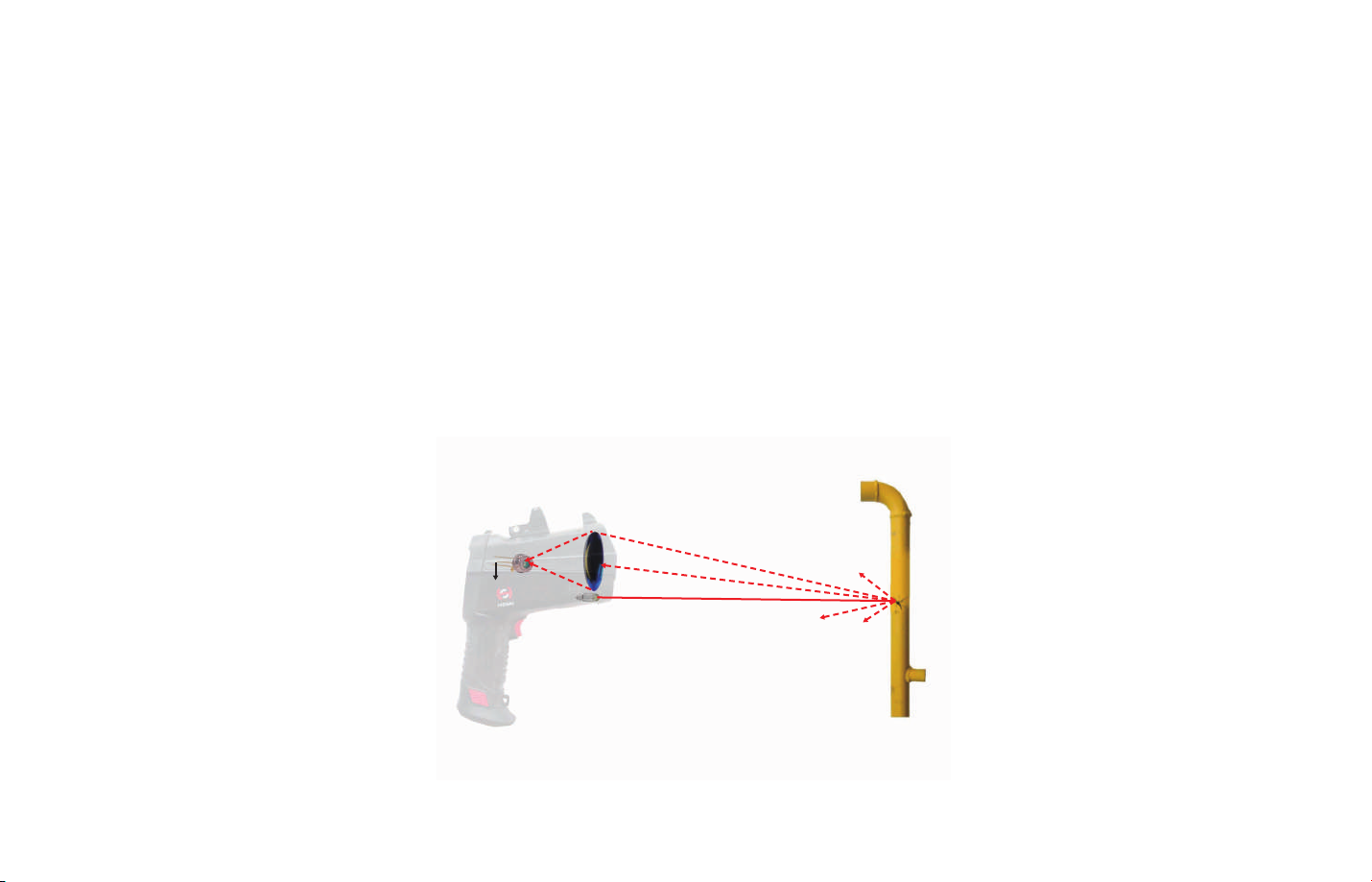
4.6.1
Case 1
When detecting through the glass, if the infrared laser is incident on the glass vertically, part of the light reflected by the glass will be
received by the device, which will cause light intensity saturation or inaccurate measurement result.
In such case, please point as shown in Figure 4.6.B to avoid receiving the glass reflected light.
4.6.2 Case 2
Please avoid detecting through materials that have
strong absorption or reflection effect on the infrared
laser, such as PMMA, laminated glass, anti-infrared
glass. In such case, the methane concentration behind
can't be detected or the measurement result may be
inaccurate.
A B
Figure 4.6 Do's and Don'ts when detecting through the glass
Figure 4.7 Avoid detecting through anti-infrared or absorbing infrared material
-19-

4.6.3 Case 3
When detecting towards the corner (or similar situation), as shown in Figure 4.8.A, the infrared laser may reflect between walls, resulting
in high measurement concentration. In such case, please point as shown in Figure 4.8.B to have the accurate measurement result.
BA
Figure 4.8 Do's and Don'ts when detecting the corner
-20-

Technical Support and Maintenance5
5.1
Error Messages
5.1.1 Error Code
Error Code
0x01
0x02/0x03
0x04/0x05
0x08/0x09
0x10/0x11
Description
Laser temperature control system is abnormal
Laser intensity in the reference channel is too weak
Circuit board temperature exceeds the range of -20 to +80℃
Laser shell temperature exceeds the range of -20 to +60℃
Unable to detect the absorption signal in the reference channel
5.1.2 Proper Handling Method
When the error message appears, try restarting the device. If error code 0x01\0x04\0x05\0x08\0x09 appears, please try to restart the
device after it is completely cooling down.
If the error still exists, please contact Hesai for the technical support.
NOTE Do not try to repair the device on your own accord.
Table 5.1 Error Code Explanations
Figure 5.1 Error Messages
-21-

5.2
Trouble Shooting
The instrument cannot be turned on.
1)
Please reinstall the battery, wait 5 seconds, then press the power button to turn on the instrument. If the instrument still cannot turn on
within 30 seconds, please check whether it is out of battery.
The instrument's alarm is always on or never on.
2)
Please check whether the alarm threshold value is set too high or too low.
The instrument's alarm is on, but there is no sound.
3)
Please check the volume of the instrument. Make sure that the alarm is on and the volume is set properly.
The battery cannot be charged.
4)
Please check whether all the components are connected well.
Please check whether the charging base has power.
Please check whether the battery is plugged into the charging base.
The instrument is in good condition but there is no reading.
5)
Please check whether the light intensity is too strong or too low.
When light intensity is too strong, please avoid complete perpendicular between the detecting laser beam and the object reflective surface.
-22-

5.3
Warranty and Maintenance
5.3.1 Warranty
During the warranty period, Hesai will provide free maintenance service when the device can't operate due to the problem of software or
hardware. But Hesai will not provide the service if the problem is caused by improper or unauthorized operations. Situations that break the
warranty include but are not limited to the following:
Missing warranty document or effective purchase vouchers.
1)
Did not use the instrument as per these instructions.
2)
Unauthorized modification, disassembly, or repair.
3)
Intentional damages.
4)
Stolen, lost or discarded device.
5)
Damaged device due to use with unauthorized accessories and services.
6)
Those damages caused by natural disasters, such as fire, lightning, flood, earthquake, etc.
7)
5.3.2 Maintenance
For maintenance requirement, please follow the following steps:
1)
Report the problem to Hesai for the preliminary problem diagnose and receive Return Material Authorization (RMA).
2)
Delivery product to Hesai.
3)
Hesai provides the maintenance test report, maintenance fee (if any), and repair agreement.
4)
Pay the maintenance fee if needed.
5)
Receive the repaired instrument and finish delivery inspection.
Normal Maintenance Time (after receiving the product): 7 days.
The specific maintenance time shall be determined according to actual repairs or service needed.
-23-

Appendix I FCC Statement
FCC ID: 2ASO2HS4000
This equipment has been tested and found to comply with the limits for a Class B digital device, pursuant to Part 15 of the FCC Rules. These
limits are designed to provide reasonable protection against harmful interference in a residential installation. This equipment generates, uses
and can radiate radio frequency energy and, if not installed and used in accordance with the instructions, may cause harmful interference to
radio communications.
However, there is no guarantee that interference will not occur in a particular installation.
If this equipment does cause harmful interference to radio or television reception, which can be determined by turning the equipment off
and on, the user is encouraged to try to correct the interference by one or more of the following measures:
· Reorient or relocate the receiving antenna.
· Increase the separation between the equipment and receiver.
· Connect the equipment into an outlet on a circuit different from that to which the receiver is connected.
· Consult the dealer or an experienced radio/TV technician for help.
NOTE Any changes or modifications not expressly approved by the grantee of this device could void the user's authority to operate the
equipment.
-24-

Hesai Photonics Technology Co., Ltd
Phone: 021-80394947-802
Technical Support: 021-80394947-896
Website: www.hesaitech.com
Business Email: info@hesaitech.com
Service Email: service@hesaitech.com
Address: Building L2-B, Hongqiao World Centre, Shanghai
HESAI WeChat
 Loading...