

Drone-mounted Remote
Methane Leak Detector
User’s Manual
www.hesaitech.com
100-en-1901B2
HESAI WeChat

Notice
Please read this manual carefully before using the equipment.
CAUTION
To avoid violating the warranty and to minimize the chances of getting electrically shocked, please do not disassemble the device on your
own accord. The device must not be tampered with and must not be changed in any way. There are no user-serviceable parts inside the
device. For repairs and maintenance inquiries, please contact an authorized Hesai Technologies service personnel.
DISCLAIMER
The information contained within this user’s manual and the functions offered is intended to provide information about products. All
reasonable efforts have been made to ensure the accuracy of the information. However, Hesai cannot be held responsible for any errors.
Hesai does not warrant the accuracy and reserves the right to make changes to the catalog and its functions at any time without notice.

Table of Contents
1
2
3
4
5
Safety Notice
Introduction
Specifications
Installation Guide
4.1 Installation Notice
4.2 Mechanical Installation
4.3 Interface Introduction
UART Serial Port Data and
Parameter Configuration
5.1 UART Serial Port Data Output
01
02
03
04
05
06
07-08
Appendix I
Warranty and Maintenance
Appendix II
EC-Declaration of Conformity
Appendix III
FCC Statement
10
11
12
5.2
Parameter Configuration
09
Safety Notice1
Prior to using this product, please read the safety notices carefully to ensure the safety and to avoid any improper usage.
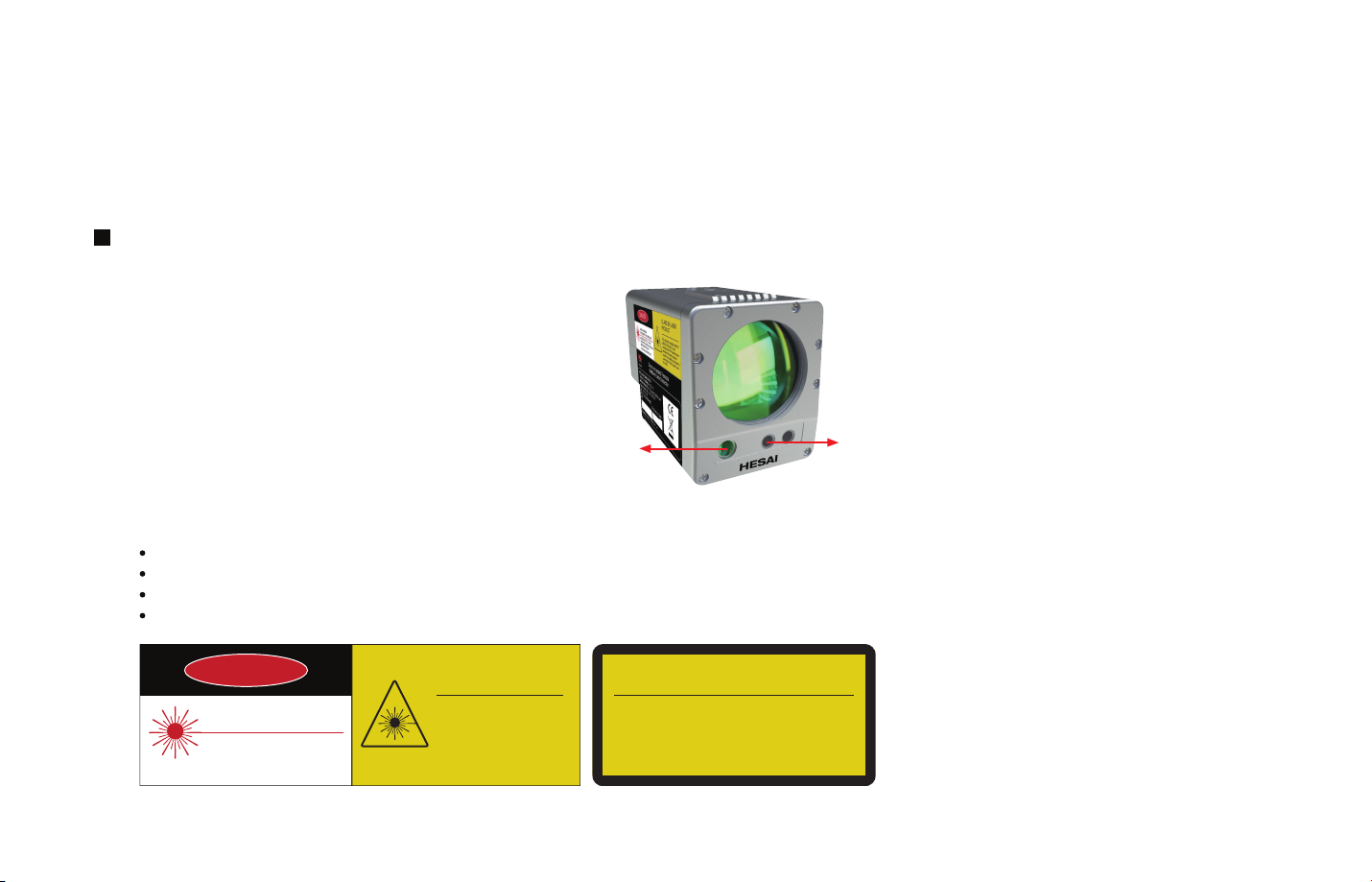
Laser Safety Notice – Laser Class 3R
Infrared Measurement Laser: Class 1 Eye Safe,
wavelength: 1651 nm, <10 mW
Green Indication Laser: Class 3R,
wavelength: 520 nm, <5 mW
Avoid Direct Eye Exposure
Infrared measurement
laser aperture
The device satisfies the requirements of:
IEC 60825-1:2014;
IEC 60825-1:2007;
21 CFR 1040.10 and 1040.11 except for deviations pursuant to Laser Notice No.50, dated June 24, 2007;
GB7247.1-2012.
Green indication
laser aperture
-01-
DANGER
LASER RADIATIONAVOID DIRECT EYE EXPOSURE
MAXIMUM OUTPUT: <5 mW
OPERATION: CW (100 ms/200 ms)
WAVELENGTH: 520 nm
CLASS IIIa LASER PRODUCT
CLASS 3R LASER
PRODUCT
(This product complies with IEC
60825-1:2014 Ed 3.0 and
complies with FDA performance
standards for laser products
except for deviations pursuant to
Laser Notice No.50, dated June
24, 2007.)
AVOID DIRECT EYE EXPOSURE
VISIBLE AND INVISIBLE LASER RADIATION
CLASS 3R LASER PRODUCT
MAXIMUM OUTPUT: <5 mW
OPERATION: CW (100 ms/200 ms)
WAVELENGTH: 520 nm
IEC 60825-1:2014 IEC 60825-1:2007
Introduction2
Hesai Drone-mounted Remote Methane Leak Detector is an ultralight and highly sensitive module that utilizes an infrared laser to remotely
detect methane leaks. It can be mounted on the drones, vehicles, and ships for applications such as pipeline survey, residential area
detection, etc.
The detector measures the methane concentration by emitting an infrared laser and receiving the laser reflection.
The reading is expressed by a methane column density (ppm*m). It is the integral of the methane concentration (ppm) and the distance (m)
on the optical path.
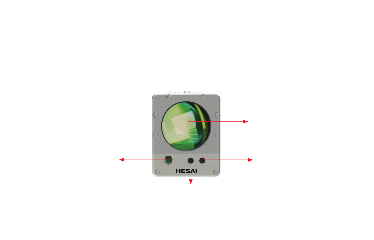
Receiving Lens
Infrared Measurement
Laser Emitter
Working Light (Blue)
Indication Laser (Green)
Figure 1. Light Instructions
-02-

3 Specifications
Target Gas
Working Principle
Sensitivity
Detection Range (CH4)
Measurement Accuracy
Response Time
Detection Distance
Weight
Size
* Specifications are subject to change without notice
Methane(CH4)and methane-containing gases
Tunable Diode Laser Absorption Spectroscopy
(TDLAS)
5 (Actual) ppm*m
0 ~ 99999 ppm*m
±10% (100~50000 ppm*m)
0.1 s (configurable)
5 m~50 m (Actual distance may vary due to
background type and conditions)
< 600 g
Operating Voltage
Rated Current
Data Output
Laser Classes
Operating Temperature
Operating Humidity
Enclosure Level
Beam Size Divergence angle: 2 mrad(4 cm at 20 m)70 mm*87 mm*120 mm
Table 1. Main Specifications
DC 7~12 V
<1 A
0.3 A (typical value) under 8 V power supply
Methane concentration, light intensity,
temperature, etc.
Infrared Laser: Class I Eye Safe
Wavelength: 1651 nm, <10 mW
Green Indication Laser: Class 3R, Avoid direct
eye exposure
Wavelength: 520 nm, <5 mW
-20℃~+50℃
< 80%RH, Non-condensing
IP54
-03-

Installation Guide4
4.1 Installation Notice
Prior to installing the detector, please read the notes carefully to ensure safe and appropriate usage:
Supply the detector as required (DC 7~12 V).
1)
Provide good heat dissipation to the laser.
2)
Pay attention to static electricity. Please release the body static electricity or wear antistatic bracelet before the installation.
3)
Do not weld/replace any component unless it is recognized by Hesai.
4)
Do not unplug the laser fiber. Do not bend the fiber even at a small angle.
5)
Do not attempt to remove any circuit boards unless it is recognized by Hesai.
6)
Do not use the PCB of detector A on detector B.
7)
Do not disassemble or repair the device on your own accord. For repairs and maintenance inquiries, please contact an authorized Hesai
8)
Technologies service personnel.
It is recommended that the length of the external cable should not exceed 3m.
9)
-04-

4.2 Mechanical Installation
There are two mechanical mounting holes on the top of the detector for the horizontal installation, and four mechanical mounting holes at the
back of the detector for the vertical installation. The mechanical drawing of the detector is shown below.
2 mm×M3 4
60.00 mm
4 mm×M4 5
52.50 mm
28.00 mm
-05-
Figure 2. Detector Mechanical Drawing

Interface Introduction4.3
The interfaces are at the back of the detector. Descriptions of the interfaces are shown below.
2
3
Type A 4-conductor plug Type A 4-conductor socket
1
1
4
Figure 3. Detector Interfaces
Interface Description
1 Positive power supply, DC 7-12V, Rated Current <1A
2 Negative power supply, GND
3 Data output, TX
4 Data input, RX
Table 2. Detector Interfaces
2
3
4
-06-

5
UART Serial Port Data and Parameter Configuration
UART Serial Port Data Output5.1
Serial Port Configuration
Baud Rate: 57600; Data: 8 bytes; Stop: 1 byte; Parity: None.
Data Format
After power-on, the detector will use around 3 seconds to complete the self-test. If there is an issue, the detector will
repeat self-testing until the problem is solved. After booting up, the serial port will send out data in the following format:
-07-
$
Methane
Concentration
5 bytes
00318,
Header
Data Description
Methane Concentration the unit is ppm*m
Light Intensity the light intensity of infrared detection laser
Relevancy reference value of whether the signal is distorted, <00980, no outputs
Environment Temperature measured from PCB board thermistor
SNR signal to noise ratio reference value
Version Number used to record the software version number, e.g. 011
Light
Intensity
5 bytes
02147,
5 bytes
00735,
Relevancy
*1000
5 bytes
00999,
Environment
Temperature
5 bytes
00036,
Table 3. Outputs Data Format
5 bytes
00024,
5 bytes
-0078,
5 bytes
00000,
SNR
3 bytes
003,
Reserved
Bytes
3 bytes
000,
Version
Number
3 bytes
010,
Error
Code
3 bytes
000
Checksum
*3C

Data Description
000
Error Code
Checksum
normal operation;
001
temperature control failure;
002
laser diode error;
Starting character is ‘*’, and the Checksum value is obtained by the data difference or operation between '$' and' * '.
Checksum calculation example:
unsigned char CalcChecksum(unsigned char* str, int len)
{
unsigned char cs;
int i;
cs = 0;
for (i=0; i<len; i++)
{
cs ^= str[i];
}
return cs;
}
004
circuit board temperature exceeds -20~80℃;
008
laser case temperature exceeds -20~80 °C;
016
reference channel error.
Table 4. Data Description
Error Code Proper Handling Method
When the error message appears, try restarting the device. If error code 001, 004, or 008 appears, please try to restart the device after it is
completely cooling down. If the error still exists, please contact Hesai for the technical support.
NOTE Do not try to repair the device on your own accord.
-08-

5.2
Parameter Configuration
Users can use the serial port debugging tool to configure parameters for the detector. The specific configuration parameters are as follows:
Functions
Enter configuration mode
Set measurement time
Set save power
Set wakeup
Set SNR
Set light intensity threshold
Get device information “DSP\r\n” “DeviceSN:%s\r\n
Set green indication laser “SGL,ON\r\n”
Reset
Exit
Command
“+++\r\n”
“SSPD,%f\r\n”
“SD,Savepower\r\n”
“SD,Wakeup\r\n”
“SSNR,%f\r\n”
“SITH,%d\r\n”
“SGL,OFF\r\n”
“SF,1\r\n”
“---\r\n”
DM100 Return Description
“WELCOME\r\n”
“AOK\r\n”
“AOK\r\n”
“AOK\r\n”
“AOK\r\n”
“AOK\r\n”
LaserSN:%s\r\n
SetTld:%x\r\n
IS1651:%d\r\n
SNRThreshX10:%d\r\n
IntensityThresh:%d\r\n”
“AOK\r\n” Default setting: ON
“AOK\r\n”
“END\r\n”
Table 5. Parameter Configuration
Serial port configuration is only valid in configuration mode
Default setting: 0.1 s. Options: 0.1 s~10 s
-
-
Default setting: 2. Options: 0.1~10
Default setting: 100,Options: 50~1000 (integer)
Example:
“DeviceSN:HESAI194
LaserSN:ABCD1234
SetTld:825
IS1651:1
SNRThreshX10:10
IntensityThresh:100”
Restore system default setting
Enter test mode after exiting configuration mode
* After sending the configuration command, the system returns the value "AOK\r\n"; if the command is incorrect, it returns "ERR\r\n".
End a command with “\r\n”.
-09-

Appendix I Warranty and Maintenance
Warranty
During the warranty period, Hesai will provide free maintenance service when the device can't operate due to the problem of software or
hardware. But Hesai will not provide the service if the problem is caused by rule-breaking operations. Situations that break the warranty
include but are not limited to the following:
1)
Missing warranty document or effective purchase vouchers;
2)
Did not use the instrument as per instructed;
3)
Unauthorized modification, disassembly, or repair;
4)
Intentional damages;
5)
Stolen, lost or discarded device;
6)
Damaged device due to use with unauthorized accessories and services;
7)
Those damages caused by natural disasters, such as fire, lightning, flood, earthquake, etc.
Maintenance
For maintenance requirement, please follow the following steps:
1)
Report the problem to Hesai for the preliminary problem diagnosis.
2)
Return the product to Hesai.
3)
Hesai conducts the maintenance test report, calculates maintenance fee (if any), and provides the maintenance agreement.
4)
Sign the maintenance agreement and pay the maintenance fee if needed.
5)
Receive the repaired instrument and finish the delivery inspection.
Normal Maintenance Time (after receiving the product): 7 days. The specific maintenance time shall be determined according to the actual
situation.
-10-

Appendix II EC-Declaration of Conformity
-11-

Appendix III FCC Statement
FCC ID:2ASO2DM100
This device complies with part 15 of the FCC Rules. Operation is subject to the following two conditions:
(1) This device may not cause harmful interference, and (2) this device must accept any interference received, including interference that
may cause undesired operation.
Please note that changes or modifications not expressly approved by the party responsible for compliance could void the user’s authority to
operate the equipment.
Note: This equipment has been tested and found to comply with the limits for a Class B digital device, pursuant to part 15 of the FCC Rules.
These limits are designed to provide reasonable protection against harmful interference in a residential installation. This equipment
generates, uses and can radiate radio frequency energy and, if not installed and used in accordance with the instructions, may cause harmful
interference to radio communications. However, there is no guarantee that interference will not occur in a particular installation. If this
equipment does cause harmful interference to radio or television reception, which can be determined by turning the equipment off and on,
the user is encouraged to try to correct the interference by one or more of the following measures:
—Reorient or relocate the receiving antenna.
—Increase the separation between the equipment and receiver.
—Connect the equipment into an outlet on a circuit different from that to which the receiver is connected.
—Consult the dealer or an experienced radio/TV technician for help.
-12-

Hesai Photonics Technology Co., Ltd
Address: 10th Floor, Building L2-B, Hongqiao World Centre, Shanghai
Sales: 021-80394947-802
Business Email: info@hesaitech.com
Website: www.hesaitech.com
Technical Support: 021-80394947-896
Service Email: service@hesaitech.com
HESAI WeChat
 Loading...