

Page 1
Installation Instructions
®
Vista V3 Electric Strike
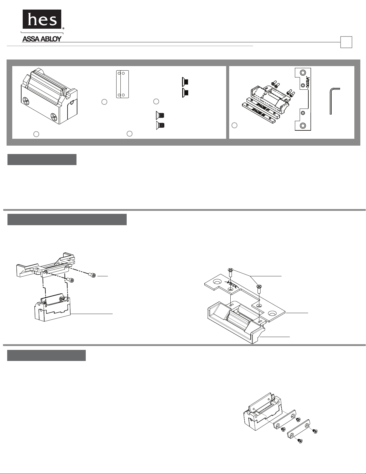
Product Components
HES, Inc.
Phoenix, AZ
800-626-7590
www.hesinnovations.com
1
2
15/16”
Keeper Shims
1-13/16”
1
Strike Body
13/16”
4
4-40 x 3/16” Shim Screws
Strike Installation
1. If this is a new installation, consult pages 2-3 for the
proper template for your option.
Faceplate and Housing Assembly
3. Attach Electric Strike body to Housing as illustrated
below using the 6-32 x 5/16” socket head screws and hex key
packaged with the Option Kit.
6-32 x 5/16”
Socket Head
Screws
3
4-40 x 1/8” Shim Screws
2. If you are replacing another manufacturer’s electric strike,
rst determine the manufacturer and model number to be
replaced. Using the chart on page 4, choose the appropriate
Option Kit and spacer to be used with the new install and
proceed to step 3.
4. If using Options 1-4, attach Faceplate to Housing as illustrated
below using the 6-32 x 7/16” at-head screws provided with the
Option Kit.
Note: A second set of mounting holes is provided in the Housing
for additional Forward Horizontal Adjustment.
5
Option Kit
(sold separately)
6-32 x 7/16” Faceplate
screws
Strike Body
Complete Installation
5. Install Electric Strike assembly into frame to test latchbolt
interaction.
7. Remove Electric Strike from frame and connect power.
Faceplate
Housing
6. If additional horizontal adjustment is needed, 1 or 2 keeper
shims can be added as illustrated below. If adding a single shim
use the 4-40 x 1/8” screws, or if adding both shims, the longer
4-40 x 3/16” screws should be used.
8. Re-install the electric strike into jamb cutout using the
12-24 at-head screws provided in the Option Kit to complete
installation.
Page 2
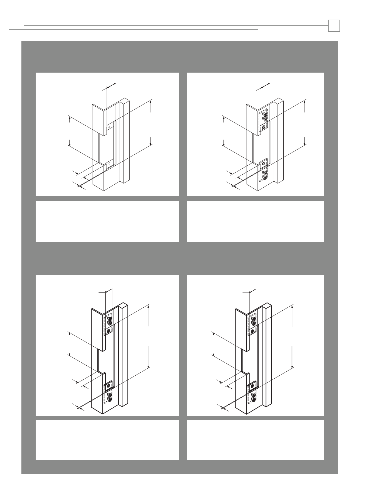
Cutout Templates
2
OPTION 1
4-7/8” x 1-1/4” Square Corner Faceplate
ANSI Metal Jamb Installations
NEW INSTALLATION
1 -1/4"
[31.8]
3 -3/8"
[85.7]
21/32"*
[16.7]
3/32"
[2.3]
RETROFIT: COMPATIBLE CUTOUTS
RCI 4114
RCI 7114
*Dimension shown without spacer
ROFU 1702
ROFU 1802
4 -7/8"
[124]
Trine 012
Trine 2007
Trine 2012
Inches
[mm]
OPTION 1A
4-7/8” x 1-1/4” Radius Corner Faceplate
Metal Frame Installations With Mounting Tabs
NEW INSTALLATION
1 -1/4"
[31.8]
3 -3/8"
[85.7]
21/32"*
[16.7]
3/32"
[2.3]
RETROFIT: COMPATIBLE CUTOUTS
RCI 4104
RCI 7104
*Dimension shown without spacer
4 -7/8"
[124]
Inches
[mm]
OPTION 2
7-15/16” x 1-7/16” Radius Corner Faceplate
Metal Frame Installations With Mounting Tabs Metal Frame Installations With Mounting Tabs
NEW INSTALLATION
1 -7/16"
[36.5]
3 -3/8"
[85.7]
21/32"*
[16.7]
3/32"
[2.3]
RETROFIT: COMPATIBLE CUTOUTS
RCI 7108
RCI 4108
ROFU 1704
ROFU 1804
7 -15/16"
[201.6]
Trine 2002WR
Inches
[mm]
OPTION 3
6 -7/8” x 1-1/4” Radius Corner Faceplate
NEW INSTALLATION
1 -1/4"
[31.8]
3 -3/8"
[85.7]
21/32"*
[16.7]
3/32"
[2.3]
RETROFIT: COMPATIBLE CUTOUTS
RCI 4107
RCI 7107
ROFU 1703 Trine 2678
ROFU 1803
6 -7/8"
[174.3]
Inches
[mm]
*Dimension shown without spacer *Dimension shown without spacer
Page 3

Cutout Templates
3
OPTION 4
9” x 1-3/8” Radius Corner & Flat Faceplate
Wood Frame Installations
NEW INSTALLATION
1 -3/8"
[34.9]
1 -1/4"
3 -3/8"
[85.7]
21/32"*
[16.7]
3/32"
[2.3]
RETROFIT: COMPATIBLE CUTOUTS
ANSI 9” X 1-3/8” CUTOUTS
[230]
[31.8]
9"
Inches
[mm]
OPTION 5
3-1/2” x 1-3/8” Square Corner & Flat Faceplate
Wood Frame Installations
NEW INSTALLATION
1 -3/8"
[34.9]
1-1/2 "
1 -7/8"
[38.1]
3/8"
[9.5]
3/32"
[2.4]
RETROFIT: COMPATIBLE CUTOUTS
Trine 005
[46]
3 -1/2"
[88.9]
Inches
[mm]
*Dimension shown without spacer
OPTION 6
7-15/16” x 1-7/16” Radius Corner Faceplate
Metal frame with mounting tabs or Wood Installations
NEW INSTALLATION
1 -7/16"
[36.5]
7 -15/16"
2-7/8"
[201.6]
[73]
13/16"
[20.6]
3/16"
[4.8]
Inches
[mm]
OPTION 7 & 7E
2-3/4” x 1-1/8” Square Corner Faceplate
ANSI A156.115 2-3/4”Metal Jamb Installation*
NEW INSTALLATION
1 -1/8"
[28.6]
A
C
1/8"
[3.2]
2 -3/4"
[69.9]
B
Inches
[mm]
RETROFIT: COMPATIBLE CUTOUTS
ROFU 1509
RETROFIT: COMPATIBLE CUTOUTS
ANSI A156.115 2-3/4 CUTOUTS*
A B C
Option 7* 1-1/2” [38.1] 1-7/8”[46] 5/8” [15.8]
Option 7E
2” [ 50.8] 2” [50.8] 21/32”[16.7]
Page 4

Compatibility Chart & Specications
OPTION KIT SELECTION
1. Using the chart below determine which Vista 3 Option Kit is required for your application.
Note: Depending on the product being retrotted, you are choosing both a faceplate, and spacer option.
For example, when replacing a Trine 2002WR series strike, an Option Kit 2 should
be used, as well as spacer #2. No spacer is needed if “None” is listed under spacer.
Trine
Model Vista Option Kit Spacer
2002WR 2 Spacer #2
Red/Green
Black
4
Model Vista Option Kit Spacer Used
RCI
4104 1A
Yes: Spacer #1
4114 1 Yes: Spacer #1
4107 3 Yes: Spacer #1
4108 2 Yes: Spacer #1
7104 1A
7114 1 Yes: Spacer #1
Yes: Spacer #1
Yes: Spacer #1
7107 3 Yes: Spacer #1
7108 2 Yes: Spacer #1
21/32"
[16.7]
Housing With No Spacer
7/8"
[22.2]
Housing With Spacer #1
Model Vista Option Kit Spacer Used
ROFU
1509 6 None
1702 1 None
1703 3 None
1704 2 None
1802 1 None
1803 3 None
1804 2 None
TRINE
005 5 None
012 1 Yes: Spacer #2
2002WR 2 Yes: Spacer #2
2007 1 None
2012 1 Yes: Spacer #2
2678 3 Yes: Spacer #2
13/16"
Housing With Spacer #2
ELECTRICAL SPECIFICATIONS
CAUTION! This strike is provided as either a 12 or 24 volt unit. Before connecting any device at the installation site,
verify input voltage using a multimeter. Many power supplies and low voltage transformers operate at higher levels
than listed. Any input voltage exceeding 10% of the solenoid rating may cause severe damage to the unit and will void
the warranty.
ELECTRICAL RATINGS FOR SOLENOID CONTINUOUS DUTY
12VDC
Resistance in Ohms
Amps
Solenoids are rated at +/- 10% indicated value.
*10% max duty cycle (2 min. max on time).
3603006.001 rev E
60
.20
[20.6]
INTERMITTENT DUTY*
24VDC
12-16VAC 24VAC
240 60 240
.10 .20 .10
inches
[mm]
MINIMUM WIRE GAUGE REQUIREMENTS SOLENOID VOLTAGE
12VDC 24VDC
200 feet or less
200 - 300 feet
300 - 400 feet
18 gauge
16 gauge
14 gauge
18 gauge
18 gauge
16 gauge
© 2012 HES, Inc.
 Loading...