

Page 1
Installation Instructions
HT1006 Series Electric Strike
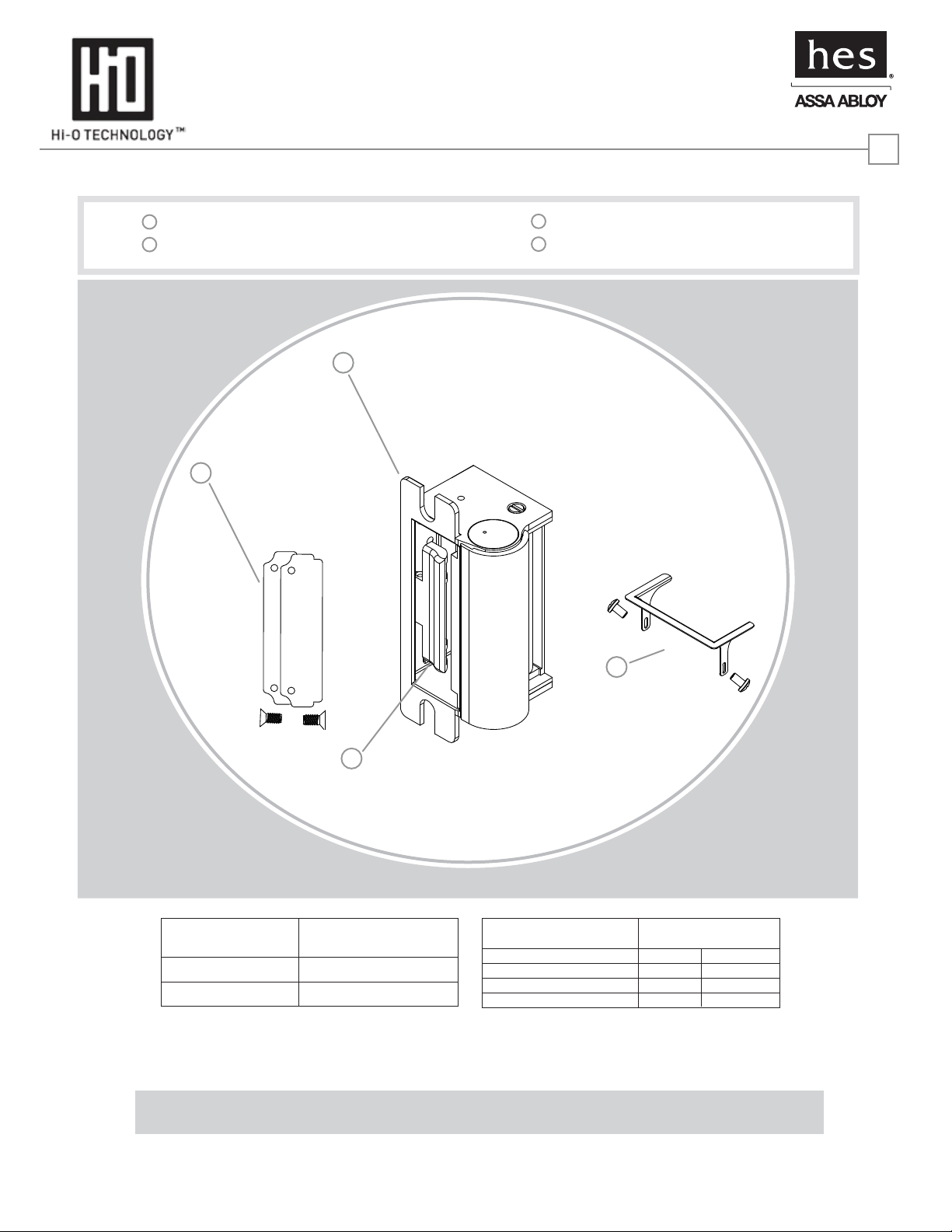
Product Components
1
1006 Electric Strike Body
2
Trim Enhancer (with screws)
1
4
3
Keeper Latchbolt Monitor
4
Keeper Shims (2, with screws)
1
2
3
ELECTRICAL RATINGS
Average Amp: 0.5 Seated
Average Amp: 0.04 Unseated
+12 to +24 (+/-10%) Volts DC
MINIMUM WIRE GAUGE Solenoid Voltage
REQUIREMENTS
200 feet or less
200 - 300 feet
16 gauge
300 - 400 feet
24 VDC
18 gauge 18 gauge
18 gauge
12 VDC
16 gauge
14 gauge
FIVE YEAR LIMITED WARRANTY
For any questions regarding this information, call HES Customer Support at 1-800-626-7590
22630 N. 17th Ave. Phoenix, AZ 85027 www.hesinnovations.com
For UL Listed applications, the unit shall be connected to a UL Listed Class 2 power supply or a UL 294 Listed control unit.
ASSA ABLOY, the global leader
in door opening solutions
Page 2
Installation Instructions
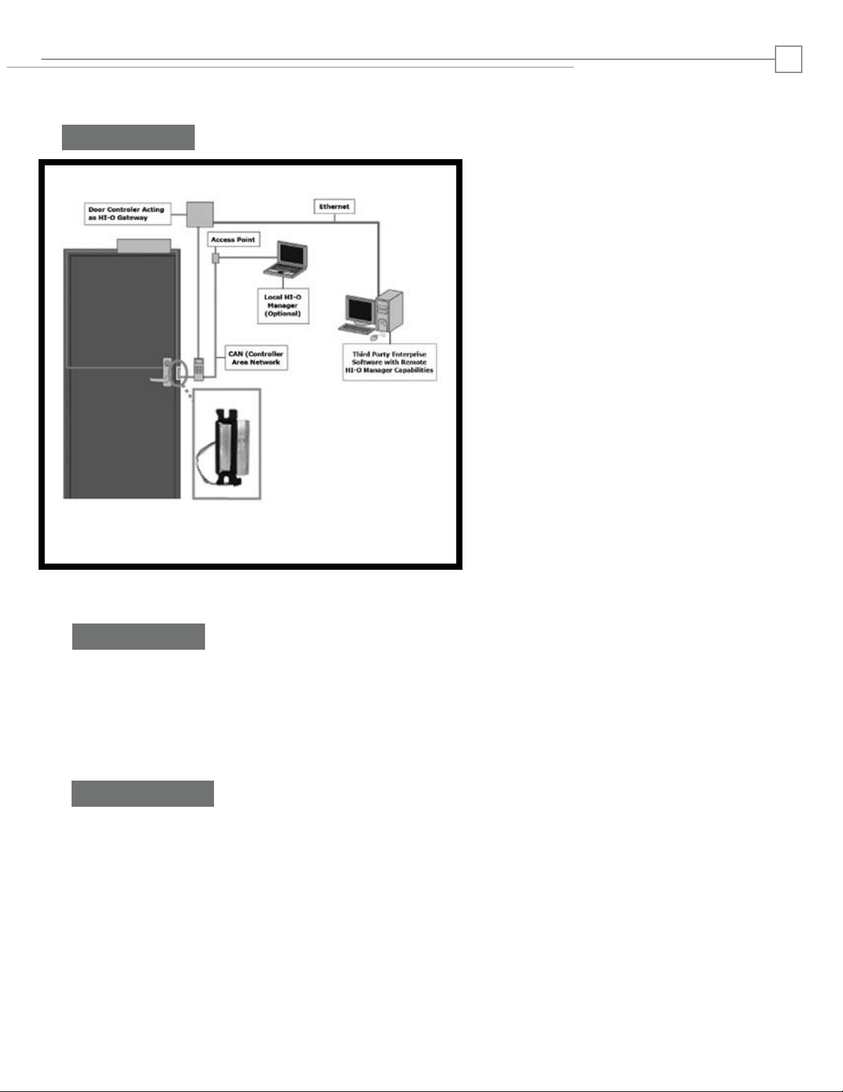
Hi-O Overview
2
ASSA ABLOY’s standard-based Hi-O system—Highly
Intelligent Opening—connects electronic door components together over a CAN (Controller Area
Network) data network, allowing them to communicate and monitor the health of the opening. Intelligence is built into each device instead of one centralized logic unit, creating a plug-and-play system. Each
device is instantly recognized when plugged into the
system—similar to what happens when a USB device is
plugged into a computer. Every unit is connected with
a four-wire cable and has ElectroLynx® plug-in
connectors for quick installation.
Hi-O is based on devices with built-in intelligence and
a CANbus that links all the devices together. Data
traffic on the Hi-O CANbus can be encrypted. Each
Hi-O device (such as a push plate, electric strike, card
reader, door operator, etc.) is connected to the
CANbus through a single, four-wire cable. Two of the
wires supply power and the other two are used for
data communication.
Prepare Strike
1. Evaluate opening and reset Dip Switch if needed
(see Adjustment Instructions on page 4).
2. For available faceplate options,
see page 9.
Prepare Frame
1. Prepare frame using the appropriate
template for your lockset and faceplate
combination (see page 8).
2. Connect to system using electrolynx
connectors (see page 3).
3. Install the HT1006 strike body into the
door frame.
Refer to the Hi-O Systems Manual (A8002).
4. Set up the Hi-O system (see pages 5-7).
Page 3
Installation Instructions
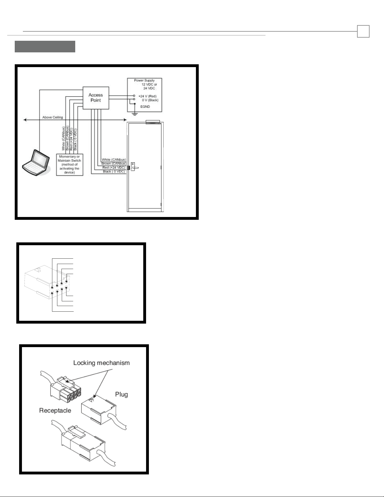
PIN 1 Black (0 VDC)
PIN 3 White (CANbus )
PIN 5
PIN 7 Brown (CANbus )
PIN 8
PIN 6
PIN 4
PIN 2 Red (+ 12 – 24 VDC)
-)]
endly with quick
cable lengths to a minimum.
.
Prepare Strike
Wiring
3
The HT1006 series drawing below show the Hi-O application
Voltage: 12-24VDC
(11-28VDC range) operation
Filtered and Regulated Power Supply
Current: .5 Amp Seated
.04 Amp Unseated
A. Electrolynx Connectors
NOTE:
For HT1006 (On the 8-Pin Connector):
PIN 2 Red (Power +12 - 24VDC)
PIN 1 Black [Power 0 VDC/Common(-)]
PIN 3 White CAN bus HIGH
PIN 7 Brown CAN bus LOW
B. Electrolynx Connector System Notes
The System is designed to be installation friendly with quick
connectors.
The total length of the bus should not be more then 50 meters
(164 feet) and stub (star) connections should not be more then
10 meters (33 feet). The optimal solution places the door
controller close to the door to keep cable lengths to a minimum.
IMPORTANT:
ElectroLynx connectors plug and lock together in only one way,
as
shown.
Do NOT force connectors together.
Page 4
Installation Instructions
The default factory settings will be used in almost every application. They are:
Group 1
Terminator OFF
NOTE: In some situations (such as mantraps) the default factory settings must be chaged. Refer to the
Hi-O Systems Manual (A8002) for additional information. If so, follow the procedure below to change
the DIP switch settings before installing strike
IMPORTANT: Ensure that the serial number of the unit is retained. Once the device is locked and
encryption enabled, access to the device requires the serial number. If the serial number is lost, the device
must be returned to the factory to be reset.
A.
B. SWITCH 1: Set the manual group switch. Default is OFF and is appropriate for most applications. Most
installations use Group 1 only.
Switch 1 OFF = membership in Group 1.
Switch 1 ON = membership in Group 2.
C. SWITCH 2: Set the termination resistor (Default is OFF). In a Hi-O CANbus network, it is necessary to
terminate the communication bus to avoid interference. Termination should take place in Activators, for
example in a card reader, opening button, or a gateway.
Switch 2 OFF removes the 120 ohm connection between CAN-Low and CAN-High.
Switch 2 ON terminates a 120 ohm resistor between CAN-Low and CAN-High.
Use only one termination resistor per application.
Refer to the Hi-O Systems Manual (A8002) for additional information.
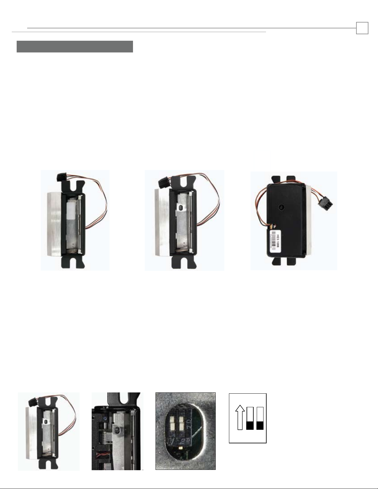
Orientation:
When you hold
the strike with the
switch oriented
towards the top of
the device, the
switch position ON
is at towards the
TOP of the device.
ON
1 2
Unit with protective label.
DIP switch location.
Serial number placement.
Adjustment Instructions
To change the settings carefully peel off the white label located on the floor of the HT1006 to access the DIP
switch. Set the label aside. Using a small tool adjust the DIP switches as described below. Then replace the
white label.
4
Page 5

Installation Instructions
Step 3
Step 3
Step 4
Step 5
Step 6
Step 1: Install hardware according to installation
instructions and the Hi-O System Manual.
Step 2: Download and install the latest release of Hi-O
Manager and Logger software, and DDF files
according to the Hi-O System Manual.
Step 3: Open Hi-O Manager and click the Next button to
determine what devices are attached to the system.
Step 4: Icons representing system appear in the left pane.
Step 5: Click the Push Button icon.
Step 6: In the Properties tab of the right pane, click the
Advanced Properties arrow to view the Properties
pane.
Step 7: In the Property Group pane, set security locking
and timers, and set the values that will generate
system messages. In the Property Group menu,
select from
the following:
Information – Read-only information from the
device.
Device Offline Behavior – Set unlock, delay
and egress timing for Lock.
Voltage Out of Range Limits – Set low and
high thresholds for voltage. When thresholds are
exceeded system messages will be generated.
Jam Timers – Set time to dictate when a jam
message is sent when the strike is locked and
keeper open.
Transmit Command Validation – Set the
above Locking, Security Locking, Opening,
Holding, Activator State, and System Voltage to
valid or invalid.
Refer to the Hi-O System Manual (A8002) for additional information.
Hi-O System Software
5
Page 6

Installation Instructions
Select the Properties tab.
Click the Push Button icon in
the view pane.
Click the Advance Properties
arrow to expand the menu.
Choose from the Properties
Groups list:
Information
Device Offline Behavior
Voltage Out of Range Limits
Jam Timers
Transmit Command Validation
Information
Displays read-only general
information from the device,
including:
Serial Number
Node ID
Host Node ID
Product Class
Application Name (Model
Number)
Hardware Version
Hi-O Stack Version
Hardware Group
ACP Active (Address Claiming
Process)
Hi-O Systems Settings
6
Page 7

Installation Instructions
7
Hi-O System Settings
De v ic e O f fl in e B e ha vi or
Vo l ta ge O ut of
Ra n ge Li m it s
Ja m T ime r s
Tr a ns mit Co mm and
Va l idat io n
Device Offline Behavior
No Change
Lock
Unlock
Set Voltage Out of Range Limits
Establishes Out of Range entries in
Log.
Low Overflow Voltage in Volts
High Overflow Voltage in Volts
11 to 28 is the normal range.
Set Jam Timers
Set time to dictate when a jam
message is sent when the strike is
locked and keeper open.
Jam Delay Timer in seconds
(0 – 255)
Set Transmit Command
Validation
Sets Locking, Security Locking,
Opening, Holding, Activator
State, and System Voltage
entries to valid or invalid,
determining if the entries are read
or ignored.
NOTE: If it is not possible to set
respective entries, check to see if
they are set to valid.
Refer to the Hi-O System Manual (A8002) for additional information
Page 8

Installation Instructions
7
Hi-O System Settings
De v ic e O f fl in e B e ha vi or
Vo l ta ge O ut of
Ra n ge Li m it s
Ja m T ime r s
Tr a ns mit Co mm and
Va l idat io n
Device Offline Behavior
No Change
Lock
Unlock
Set Voltage Out of Range Limits
Establishes Out of Range entries in
Log.
Low Overflow Voltage in Volts
High Overflow Voltage in Volts
11 to 28 is the normal range.
Set Jam Timers
Set time to dictate when a jam
message is sent when the strike is
locked and keeper open.
Jam Delay Timer in seconds
(0 – 255)
Set Transmit Command
Validation
Sets Locking, Security Locking,
Opening, Holding, Activator
State, and System Voltage
entries to valid or invalid,
determining if the entries are read
or ignored.
NOTE: If it is not possible to set
respective entries, check to see if
they are set to valid.
Refer to the Hi-O System Manual (A8002) for additional information
Page 9

Cutout Templates
8
Inches [mm]
HT1006 WITH MORTISE LOCKSETS
Please note the horizontal centerline of the electric strike
in relation to the centerline of the mortise lockset.
C
L
Mortise
Lockset
Vertical
Centerline
C
L
Strike
Prep
HT1006 WITH CYLINDRICAL LOCKSETS
Please note the horizontal centerline of the electric strike
in relation to the centerline of the cylindrical lockset.
Cylindrical
Lock
Strike
4"
[101.6]
8"
[203.2]
1-3/4"
[44.45]
C
L
Lock
1-1/4"
[31.8]
3/8"
[9.53]
1-1/4"
[31.8]
5/8"
[15.88]
4-1/8"
3-1/2"
[88.9] [104.77]
4-7/8"
[123.83]
2-1/4"
[57.15]
1-3/4"
[44.45]
C
L
Vertical
Centerline
C
L
STRIKE
C
L
LOCK
1-1/4"
[31.8]
1-1/4"
[31.8]
Strike
Prep
3-1/2"
[88.9]
5/8"
[15.88]
4-1/8"
[104.77]
4-7/8"
[123.83]
METAL JAMB INSTALLATION
FOR 1006 SERIES FACEPLATES
Cutout dimenstions for option faceplates:
J, K, KM, N, NM, Z
4-7/8"
[123.83]
4-1/8"
3-3/8"
[85.72]
1-11/16"
[42.86]
1-1/4"
[31.8]
[104.77]
2X 12-24
UNC THREADS
METAL JAMB INSTALLATION
FOR 1006 -D SERIES FACEPLATES
Cutout dimenstions for option faceplates:
KD, ND
29/32”
[23.01]
3-3/8"
[85.72]
19/32”
[15.08]
5/32”
C
L
1-11/16"
[42.86]
WOOD JAMB INSTALLATION
FOR 1006-2 SERIES FACEPLATES
Cutout dimenstions for option faceplates:
J2, K2, KM2, N2,
4-7/8"
[123.83]
4-1/8"
[104.77]
C
L
2X 12-24
1-1/4"
[31.8]
UNC THREADS
3-3/8"
[85.72]
1-3/8"
[34.92]
1-11/16"
[42.86]
9"
[228.6]
Page 10

Faceplate Options
C
= center line of faceplate
L
(2nd line = center line of faceplate opening)
ND OPTION FACEPLATE
N OPTION FACEPLATE
(4-7/8 x 1-1/4 SQUARE CORNER)
9
Inches [mm]
Inches [mm]
NM OPTION FACEPLATE
5/32”
[3.97]
KD OPTION FACEPLATE
1-1/16”
[26.72]
3-1/8”
[79.37]
23/32”
[18.26]
1-11/32”
[34.11]
23/32”
[18.22]
K OPTION FACEPLATE
29/32”
[23.39]
3-1/8”
[79.37]
7/8”
[22.23]
1-11/32”
[34.11]
27/32”
[21.46]
1/8”
[3.17]
19/32”
[15.46]
2-7/8”
[73.02]
1-9/64”
[28.83]
KM OPTION FACEPLATE
1-15/32”
[37.29]
1-3/32”
[27.81]
Z OPTION FACEPLATE
5/16”
[7.79]
1-15/32”
[37.29]
1-25/64”
[35.48]
J OPTION FACEPLATE
The HT1006 is not recommended for A,
AD, AM, A-2, E, H, HD, HM, HT, HTD, H-2,
R, T, TD, T-2 options.
1-23/32”
[43.64]
1-37/64”
[40.08]
Page 11

HT1006
ELECTRIC STRIKE
INSTALLATION INSTRUCTIONS
3062006.003 rev A
2009 HES Inc.
 Loading...