

Page 1
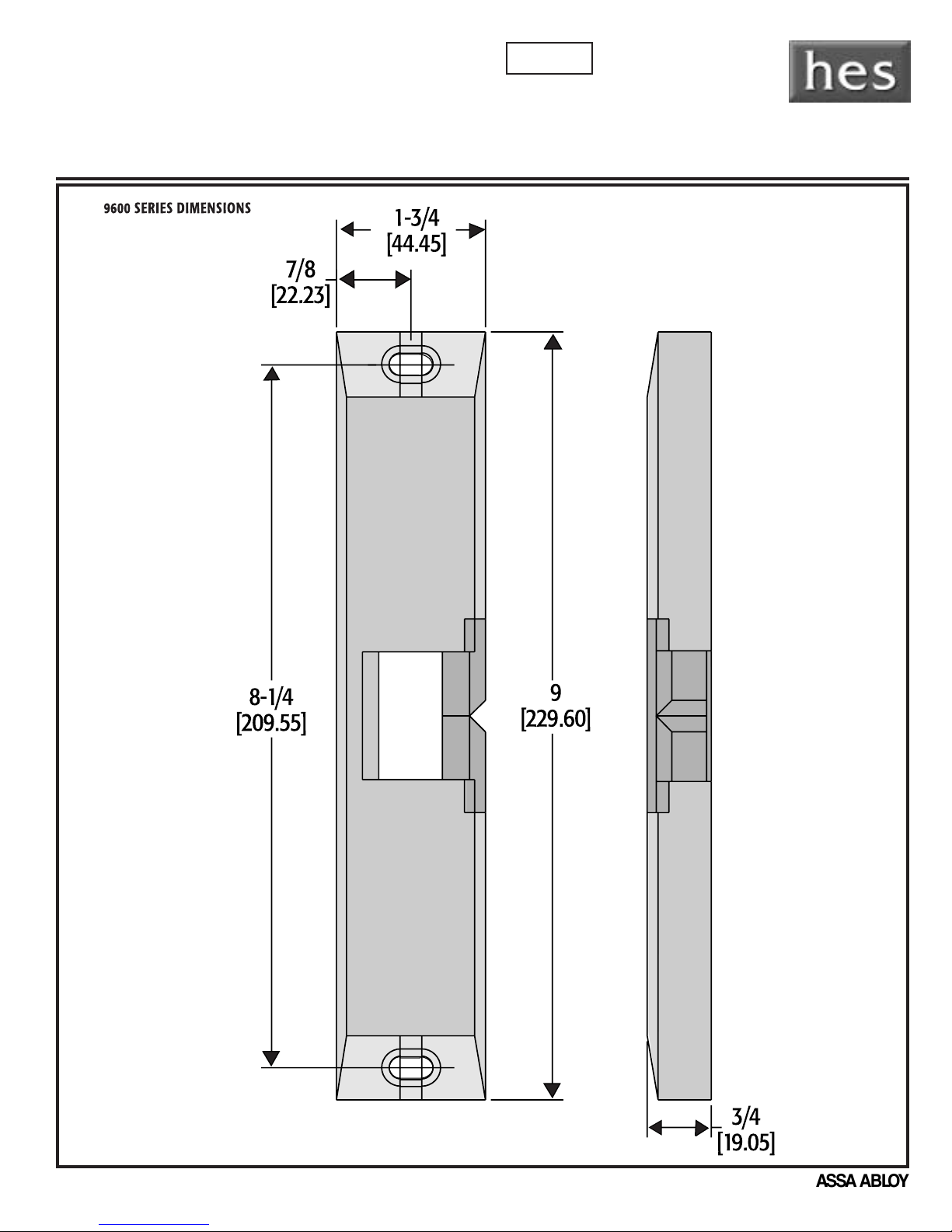
9600 GENESIS ELECTRIC STRIKE
DIMENSIONS:
INCH/MM
Surface Mounted, Dual Locking, Dual Voltage, Heavy Duty
Intended for U.L. 10C listing as a Fire Door Accessory Device (Fail Secure Only)
Intended for U.L. Burglary Resistance 1034
Hanchett Entry Systems, Inc.
2040 West Quail Ave,
Phoenix, AZ 85027
www.hesinnovations.com
Technical Service Dept. Helpline 800-626-7590
INSTALLATION INSTRUCTIONS • Please read carefully before attempting installation
NOTE: Drawings are not to scale. This information is subject to change without notice.
An ASSA ABLOY group company
© HES 2001 1
For questions, consult HES technical service helpline, 800-626-7590.
Page 2
Jamb
Face
Jamb
Reveal
8-1/4
[209.55]
9-1/8
[231.78]
Note:
Horizontal Lock
Down Screws x2
8-1/4
[209.55]
Note:
Horizontal Lock
Down Screws x2
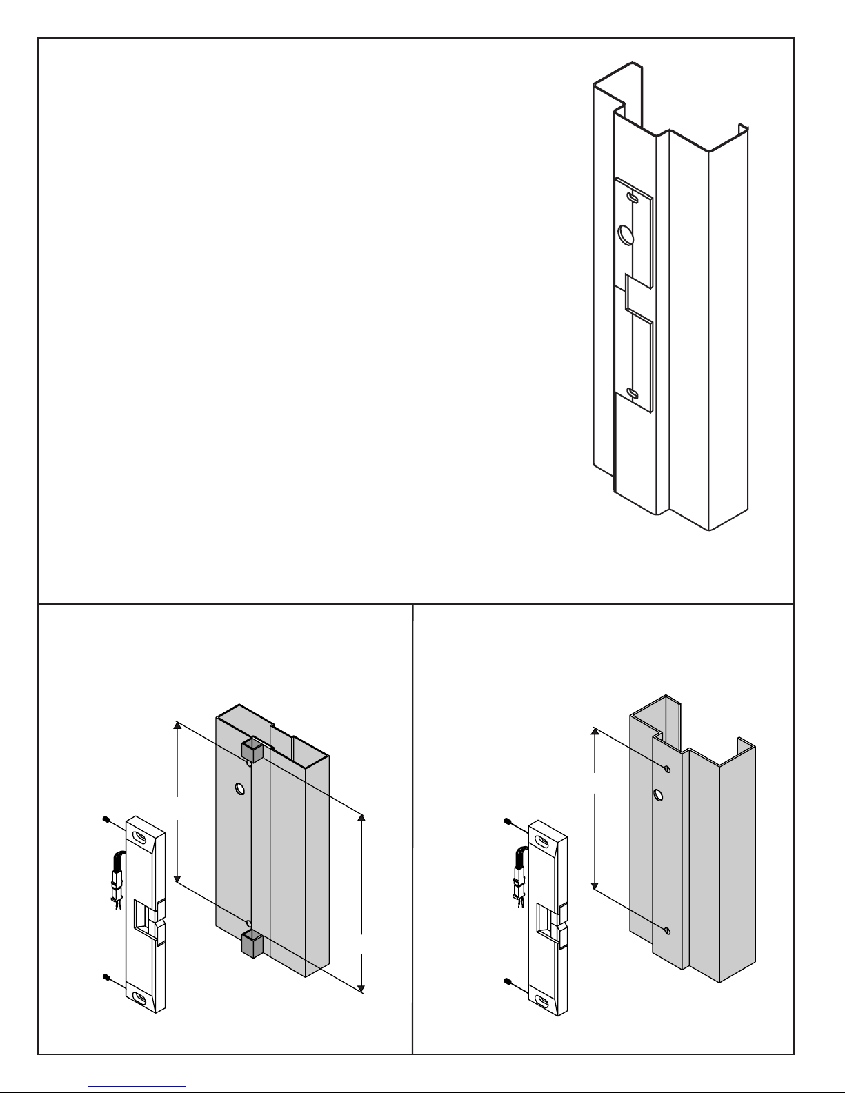
Installation Instructions
FIG 1 FIG 2
ALUMINUM JAMB INSTALLATION
METAL JAMB INSTALLATION
1. Prepare door jamb per appropriate template detail.
2. Unplug wire pigtail from electric strike.
3. Connect wires coming from the low voltage power
source (see wiring diagrams and electrical
specifications on page 4) to the electric strike pigtail.
4. Re-connect the pigtail to the electric strike.
5. Install electric strike to jamb, using 1/4 x 20 cap screws.
Further adjustments are possible by loosening 1/4 x 20
screws and sliding the strike using its slotted holes.
Note: For 12/24 AC/DC applications, see page 4.
© HES 20012
Page 3

Field Reversable
(Fail Secure to Fail Safe)
1. Remove the back cover plate.
2. Remove the two screws that are closest to the mounting hole in the strike.
3. Rotate the selector stop 180 (The L-shape should face the opposite direction).
4. Reinstall the two screws.
5. Remove the screw, holding the solenoid that is the closest to the keeper.
6. Loosen the second screw from the solenoid.
7
. Move the solenoid and any shim located under the solenoid bracket to the second
screw hole location. For Fail Safe operation the solenoid should be positioned at a
slight angle.
8. Reinstall and tighten both screws and reinstall back plate.
o
Note: Intended for Fire Rated applications (fail secure only).
© HES 2001 3
Page 4

9600 Genesis
Installation Template
Page 5

Page 6

WIRING DIAGRAM FOR 12/24 VOLTS
WIRING COLOR CODE:
White – Common
Yellow – N.O.
Orange – N.C.
Note:
Horizontal Lock
Down Screws x2
Caution: To prevent damage to the unit, cap all wires.
Note: 9600 is supplied as a 12 volt unit. For 24 volts see figure B.
12 Volts
White
Blue
RIB
Yellow
Orange
Figure A
CCAUAUTTIIOON!
N! Before connecting any device at
the installation site, verify input voltage and
current using a multimeter. Many power
supplies and transformers operate at higher
levels than listed. Any input voltage exceeding
5% of the solenoid rating may cause severe
damage to the unit and will void the warranty.
ELECTRICAL RATINGS Continuous Duty
FOR SOLENOID
Resistance in Ohms 106.6 26.6
Amps Seated .225 .45
MINIMUM WIRE GAUGE Solenoid Voltage
REQUIREMENTS
200 feet or less 18 gage 14 gage
200 - 300 feet 18 gage 12 gage
300 - 400 feet 16 gage 12 gage
24 VDC 12 VDC
24 VDC 12 VDC
Blue
White
Orange
Blue
RIB
A
9600 LATC HBOLT MONITOR:
24 Volts
Orange
Yellow
Figure B
FIVE YEAR LIMITED
WARRANTY
ELECTRIC STRIKE TROUBLE SHOOTING GUIDE
If the electric strike does not operate properly after
installation, the following problems may need to be corrected.
Please read carefully before calling for technical service.
Step 1. If the electric strike does not operate properly, open the door
and re-energize the electric strike. If the electric strike operates
properly with the door held open, the lockset may be pre-loading or
binding the keeper of the electric strike.
Solution: The horizontal relationship between the lockset and the
electric strike will have to be adjusted to eliminate the binding between
the bolt of the lock and the electric strike keeper (also See Note 2.)
Step 2. If all mechanical problems have been eliminated without
successful electric strike operation, check the following electrical
problems:
a. Examine the power supply or transformer to verify that the output
voltage is at the listed rating.
b. Verify that the power wires leading to the electric strike are a large
enough gauge to handle the current requirements (see above).
Note: Some voltage may be lost when using smaller gauge wires
over long distances.
Hanchett Entry Systems, Inc. • 2040 West Quail Ave. • Phoenix, AZ 85027 • 800-626-7590 • www.hesinnovations.com • www.electricstrikes.com
c. Using a multimeter: Verify that the input voltage is within the
recommended limits (+-5%).
d. Verify that all peripheral devices such as bridge rectifiers,
SMART-Pacs, buzzers, L.E.D.s etc. are properly connected.
e. Check that the switch, key pad, etc., meets the voltage requirements
for the system.
Note 1: A quick way to determine if an electric strike is defective is to
install it in a site where another electric strike has been installed and
working properly. Another way is to use an alternative power source to
test the electric strike (i.e. a DC battery pack.)
Note 2: If the voltage is slightly too low to operate the electric strike, a
35 volt, 220 micro-farad capacitor may be installed across the bridge
rectifier (positive to positive, negative to negative) to provide an initial
boost of power to the unit. This is also helpful to overcome slight preloading conditions (as in step 1.)
FOR ANY QUESTIONS REGARDING THIS INFORMATION, CALL
OUR
Part #LHA9600/004
TECHNICAL SERVICE LINE AT 1-800-626-7590
© HES 20014
 Loading...