

Page 1
An ASSA ABLOY Group company
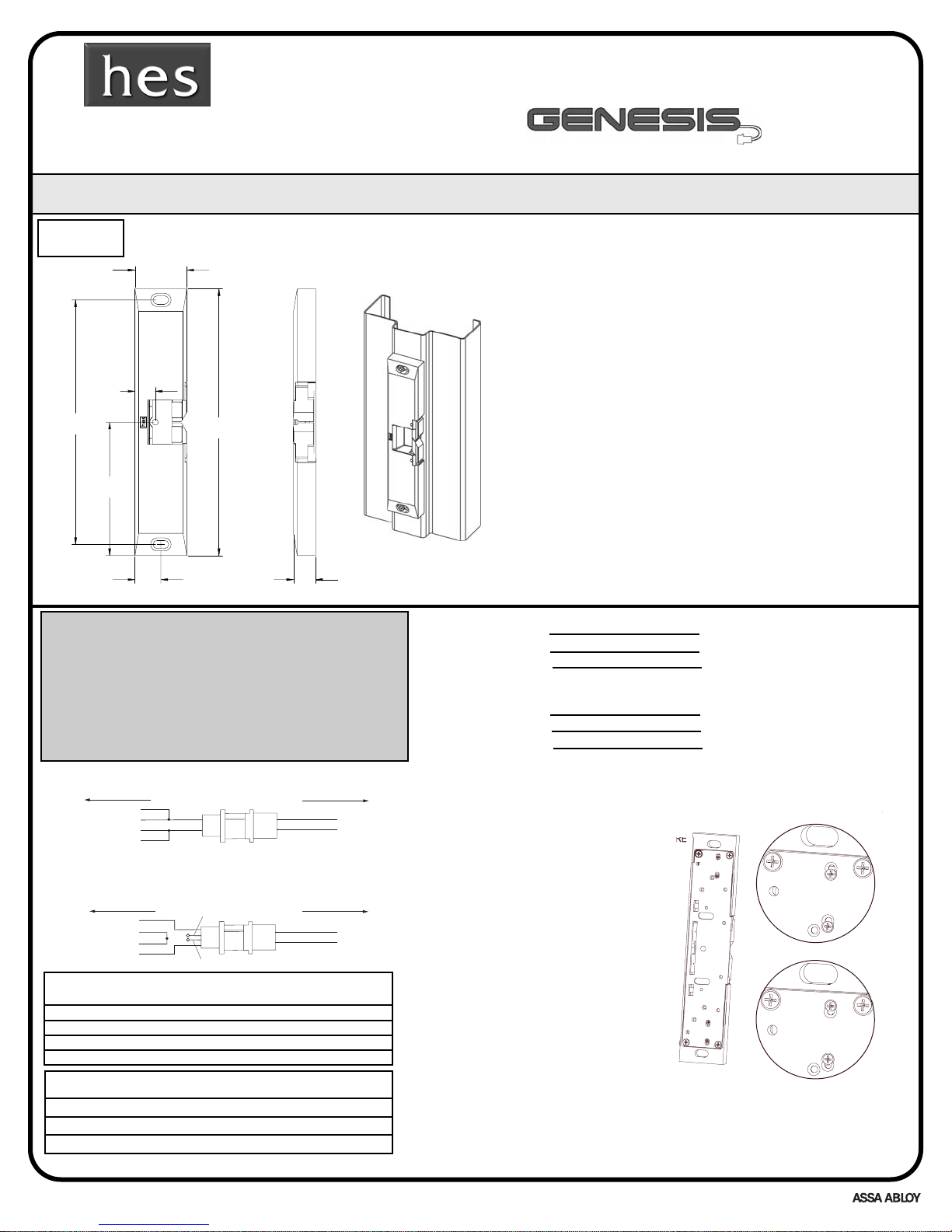
99550000 SSEERRIIEESS DDIIMMEENNSSIIOONNSS
DIMENSIONS:
INCH [[MM]
INSTALLATION INSTRUCTIONS •
PPlleeaassee rreeaadd ccaarreeffuullllyy bbeeffoorree aatttteemmppttiinngg iinnssttaallllaattiioonn
©HES 2005
1
Hanchett Entry Systems, Inc.
22630 N. 17th Ave,
Phoenix, AZ 85027
www.hesinnovations.com
(623) 582-4626
Technical Service Dept. Helpline (800) 626-7590
9"
[
]
8-1/4"
[
]
"
[44.5]
"
[
]
5/8"
[
]
3/4"
[
]
/8"
[
]
1-3/8"
[
]
4055006.001 rev C
Installation Instructions
1. Prepare door jamb using the installation template,
located on page 2 (with the exception of the 10-32 UNF
threaded hole.)
2. Connect wires coming from the low voltage power
source to the electric strike.
3. Make sure the mounting surface is smooth and
square.
4. Align and attach electric strike to jamb, using 1/4 x 20
cap screws. (Further adjustments may be made through
the # 10-32 set screws)
5. Drill and tap the 10-32 UNF threaded hole and install
the 10-32 cap screw provided (9600 optional).
NOTES:
1. The electric strike is factory supplied as a 12 Volt DC unit.
2. The electric strike is factory configured as fail secure.
3. Before supplying power to electric strike, verify source voltage and current limits are within “ELECTRICAL RATINGS FOR
SOLENOID“
4. Application on door frames only.
5. For retrofit applications, reinforcement plate must be 18
gauge minimum.
LBM WIRING COLOR CODE (optional)
WHITE COMMON
ORANGE NO-NORMALLY OPEN
GREEN NC-NORMALLY CLOSED
LBSM WIRING COLOR CODE (optional)
(in addition to wires listed above)
BROWN COMMON
BLUE NO-NORMALLY OPEN
YELLOW NC-NORMALLY CLOSED
MINIMUM WIRE GAUGE Solenoid Voltage
REQUIREMENTS
24VDC 12VDC
200 feet or less 18 gauge 14 gauge
200-300 feet 18 gauge 12 gauge
300-400 feet 16 gauge
ELECTRICAL RATINGS Continuous Duty
FOR SOLENOID
Input voltage (+ or - 5%) 24VDC 12VDC
Resistance in Ohms 106.6 26.6
Amps Seated .225 .45
E
E
1. Loosen both screws on the back.
NOTE: Do not remove screws
at any time.
2. Move up or down depending on
the operation.
3. Tighten screws.
FAIL SECURE
Field Reversible:
Fail secure - Fail safe
CAUTION! Before connecting any device at the
installation site, verify input voltage and current using
a multimeter. Many power supplies and transformers
operate at higher levels than listed. Any input voltage
exceeding 5% of the solenoid rating may cause severe
damage to the unit and will void the warranty.
12V
24V
1. Loosen the pair of 2-56 flathead
screws on the back of the electric
strike.NOTE: Do not fully remove
screws at any time.
2. Shift screws to fail safe configuration as shown at right.
3. Tighten screws.
4. Repeat steps 1-3 at other end of
electric strike.
5. Remove UL 10C label for fail safe
configuration.
9500 Intended for UL 10C, 90 min.
9500/9600
Electric Strikes
Fire rated 9500, surface mounted
1-3/4
34.9
228.6
209.6
4-1/2
114.3
17.4
7
22.2
19.1
TO ELECTRIC STRIKE
RED
VIOLET
BLACK
RED/GREEN
TO ELECTRIC STRIKE
RED
VIOLET
BLACK
RED/GREEN
VIOLET
BLACK
TO 12V DC
POWER SOURCE
TO 24V DC
POWER SOURCE
FAIL SECUR
FAIL SAF
Page 2
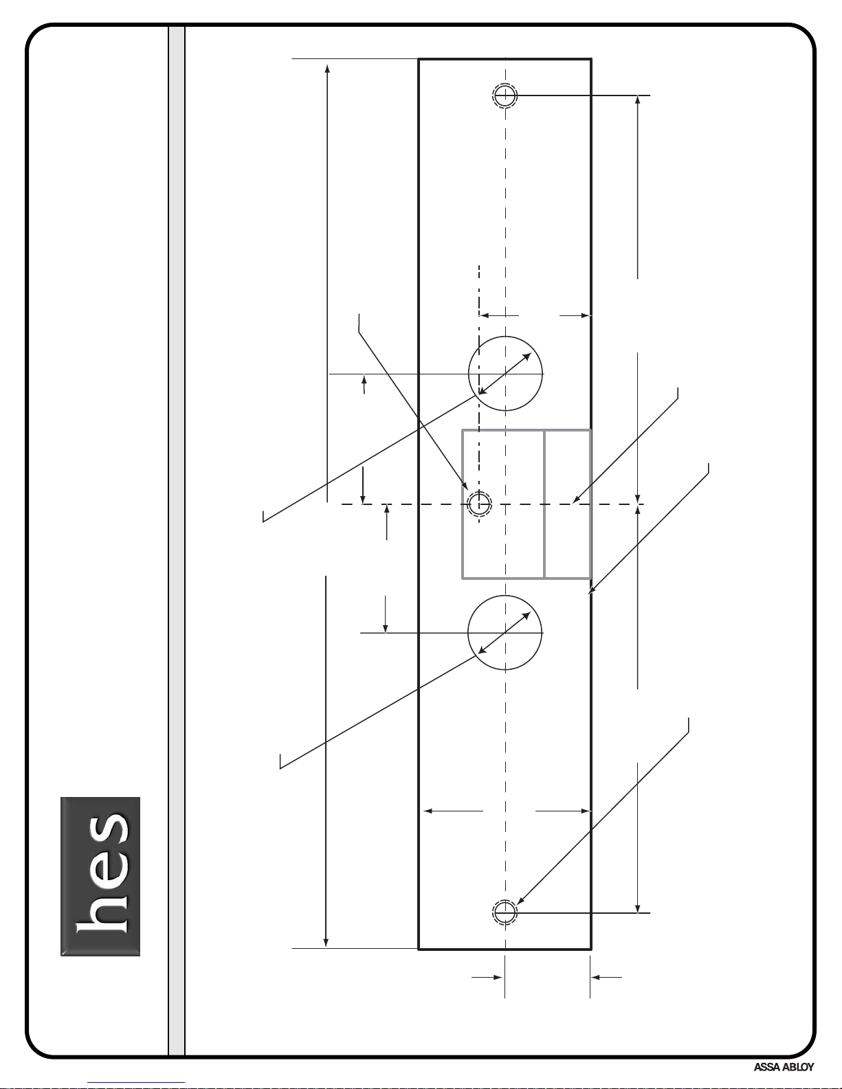
9"
[228.6]
CENTERLINE OF LATCHBOLT
THIS EDGE TOWARD DOOR
2X MOUNTING HOLE
LOCATIONS FOR
1/4-20 UNC CAP SCREWS
7/8"
[22.2]
4-1/8"
[104.8]
1-3/4"
[44.5]
[
]
OR
BM/
B
M
WIRING
[
]
O
POWER WIRING
Final Lockdown Feature
10-32 UNF (9600 OPTIONAL)
1-5/16"
[33.3]
1-5/16"
[33.3]
1-1/16"
[27.0]
4-1/8"
[104.8]
©HES 2005
An ASSA ABLOY Group company
9500/9600 LBM/LBSM
Installation Template
2
4055006.001 rev C
19.0
S
3/4"
L
CLEARANCE F
L
R
19.0
3/4"
CLEARANCE F
 Loading...