

Page 1
Installation Instructions
9400 Series Electric Strike
HES, Inc.
22630 N. 17th Ave.
Phoenix, AZ 85027
800-626-7590
www.hesinnovations.com
1
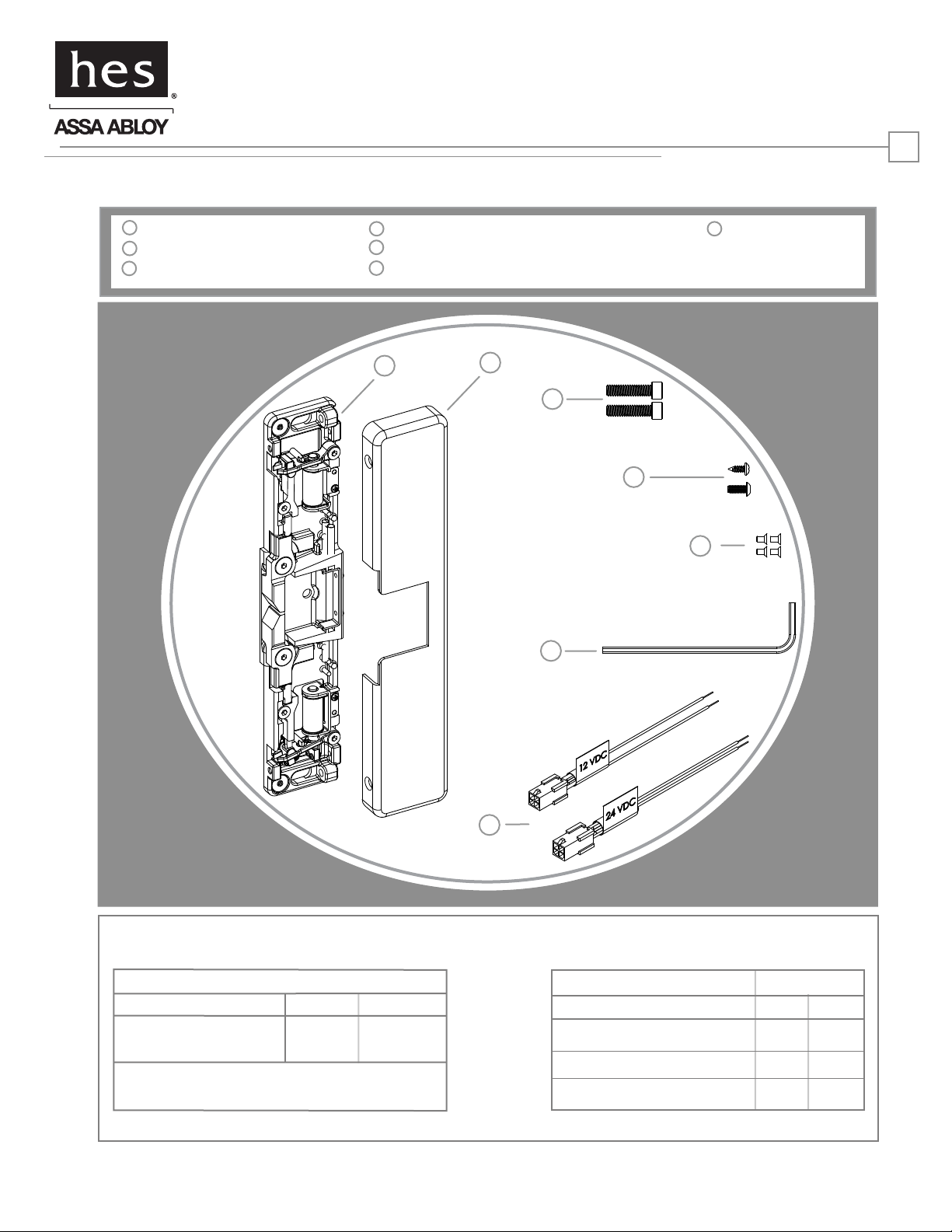
Product Components
1
9400 Electric Strike Body
2
9400 Cover
3
1/4”-20 x 1” Mounting Screws
4
#10-32 & 10-24 Lockdown Screws (optional)
5
#6-32 x 1/4” Cover Screws
6
5/64” Hex Key
1
2
7
Plug In Connectors
3
4
5
7
Diagram 1: Electrical Specifications
ELECTRICAL RATINGS FOR SOLENOID
CONTINUOUS DUTY
Resistance in Ohms
Amps
Solenoid voltage +/ - 10%
12VDC
24
.50
24VDC
96
.25
6
MINIMUM WIRE GAUGE REQUIREMENTS SOLENOID VOLTAGE
12VDC 24VDC
200 feet or less
200 - 300 feet
300 - 400 feet
18 gauge
16 gauge
14 gauge
18 gauge
18 gauge
16 gauge
ASSA ABLOY, the global leader
in door opening solutions
Page 2
Installation Directions
CAUTION! Before connecting any device at the installation site, verify input voltage using a multimeter.
Many power supplies and low voltage transformers operate at higher levels than listed. Any input voltage exceeding
10% of the solenoid rating may cause severe damage to the unit and will void the warranty.
2
Prepare Strike
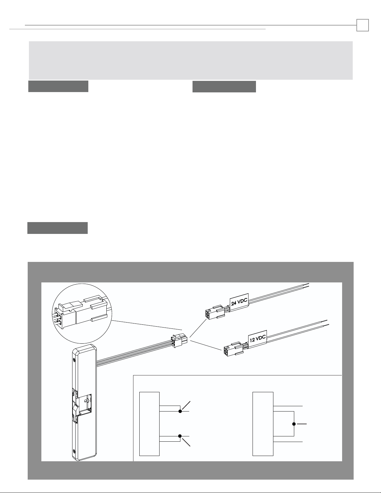
1. Select the appropriate Plug In Connector that
matches system power and electrically connect as
illustrated in Diagram 2. For 12V DC, the pigtail
marked “12 VDC” should be used. For 24V DC, the
pigtail marked “24 VDC” should be used. If no
connector is present, configure the wires as illustrated within Diagram 2.
2. If using the Latchbolt Monitor (LBM) or Latchbolt
Strike Monitor (LBSM), refer to Diagram 3 & 4 on
page 3 to complete wiring.
3. The 9400 ships in the Fail Secure mode of operation. If you need to convert to Fail Safe Operation
see Diagram 5 on page 3.
Prepare Frame
4. Prepare the door jamb using the Installation
Template located on page 4 (with the exception of
the hole for final lockdown).
Finish Installing
5. Electrically connect the 9400 to the Plug In Connector, and attach the electric strike to the jamb
using the 1/4”-20 cap screws provided.
6. Check latchbolt interaction to determine if
horizontal adjustment is needed, and adjust as
needed. Lockdown horizontal adjustment using the
#10-32 setscrews as illustrated on page 4.
7. OPTIONAL LOCKDOWN FEATURE: Install the
#10-24 UNC or 10-32 UNF lockdown screw if additional security is required. Remove the strike
before drilling hole.
8. Install the cover plate, and fix in place using the
#6-32 x 1/4” Cover Screws as illustrated on page 4.
DIAGRAM 2: 12V to 24V CONVERSION
or
IF CONNECTOR IS MISSING
CONNECT
RED
VIOLET
STRIKE
BLACK
ELECTRIC
RED/GREEN
TOGETHER
(+ 12 VDC)
(-NEG)
CONNECT
TOGETHER
ELECTRIC
RED
VIOLET
STRIKE
BLACK
RED/GREEN
(+ 24 VDC)
CONNECT
TOGETHER
(-NEG)
Page 3

Installation Diagrams
3
DIAGRAM 4: STRIKE MONITORDIAGRAM 3: LATCHBOLT MONITOR
LBM WIRING
White
Orange
Green
Common
Normally Open
Normally Closed
White
Orange
Green
DIAGRAM 5: CYLINDRICAL LOCKSETS
DIAGRAM 5: FAIL SAFE CONVERSION
Convert Mode
The 9400 series Electric Strike is pre-set
for FAIL SECURE OPERATION as shown in
Figure 1.
There are Selector Stop Pins, one on the left
side and one on the right side. Both Selector
Stop Pins must be repositioned to convert
the strike to Fail Safe Operation.
LBSM WIRING
Brown
Blue Normally Open
Yellow
Yellow
Common
Normally Open
Normally Closed
Normally Closed
Brown
Blue
Yellow
Figure 1: FAIL SECURE OPERATION
1. To convert to Fail Safe Operation, remove
the Selector Stop Pins on each side of the
strike body using the 5/64” hex key
provided.
2. Move the Selector Stop Pins to the Fail
Safe Operation position as pictured
(towards the center of the strike) in Figure 2.
3. Tighten both Selector Stop Pins after they
have been moved to the Fail Safe Operation
Verify
Verify that both keepers are in Fail Safe
Operation. Both keepers should be
unlocked without power, but lock when
power is applied.
Selector Stop
Pin Location
Figure 2: FAIL SAFE OPERATION
Selector Stop
Pin Location
Page 4

Frame Preparation
HORIZONTAL ADJUSTMENT & LOCKDOWN
Inches [mm]
4
SETSCREW
LOCATION
MOUNTING
SCREW
LOCKDOWN
SCREW
(optional)
SETSCREW
LOCATION
MOUNTING
SCREW
1. Loosen the two #1/4-20 mounting screws.
2. Adjust strike to appropriate horizontal position.
3. Tighten the two #1/4-20 mounting screws.
4. Lock down adjustment by tightening the setscrews.
5. Install the #10-32 UNF or 10-24 UNC lockdown
screw (optional).
COVER INSTALLATION
9"
Final Lockdown Feature
1-5/16"
[228.6]
[44.5]
1-3/4"
1/2” [12.7]
CLEARANCE FOR
LBM/LBSM WIRING
10-32 UNF or 10-24 UNC (optional)
1-1/16"
4-1/8"
[27.0]
[33.3]
[104.8]
CENTERLINE OF LATCHBOLT
THIS EDGE TOWARD DOOR
Attach the cover using the #6-32 x 1/4” Cover Screws
1-5/16"
[33.3]
3/4” [19]
POWER WIRING
CLEARANCE FOR
4-1/8"
[104.8]
LOCATIONS FOR
2X MOUNTING HOLE
1/4-20 UNC CAP SCREWS
3075006.002 rev B
© 2009 HES, Inc.
7/8"
4X
[22.2]
 Loading...