

Page 1
Installation Instructions
8000/8300 Series Electric Strike
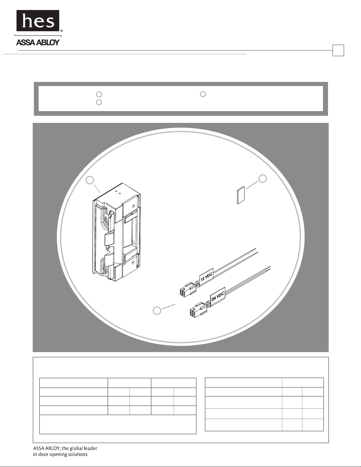
Product Components
1
8000/8300 Electric Strike Body
2
Sticky Shims (optional use)
3
12 & 24 Volt Pigtails
HES, Inc.
22630 N. 17th Ave.
Phoenix, AZ 85027
800-626-7590
www.hesinnovations.com
1
1
3
2
Diagram 1: Electrical Specifications
ELECTRICAL RATINGS FOR SOLENOID
Resistance in Ohms
Amps
Solenoids are rated at +/- 10% indicated value.
*10% max duty cycle (2 min. max on time)
CONTINUOUS DUTY
12VDC
50
.24
24VDC
200 50 200
.12 .12
INTERMITTENT DUTY*
12-16VAC 24VAC
.24-.32
MINIMUM WIRE GAUGE REQUIREMENTS SOLENOID VOLTAGE
200 feet or less
200 - 300 feet
300 - 400 feet
12VDC
18 gauge
16 gauge
14 gauge
24VDC
20 gauge
18 gauge
16 gauge
Page 2
Installation Directions
CAUTION! Before connecting any device at the installation site, verify input voltage using a multimeter.
Many power supplies and low voltage transformers operate at higher levels than listed. Any input voltage exceeding
10% of the solenoid rating may cause severe damage to the unit and will void the warranty.
Evaluate Opening
2
1. Verify opening is plumb and square. For important detail,
see “Read Me” guide.
Prepare Strike
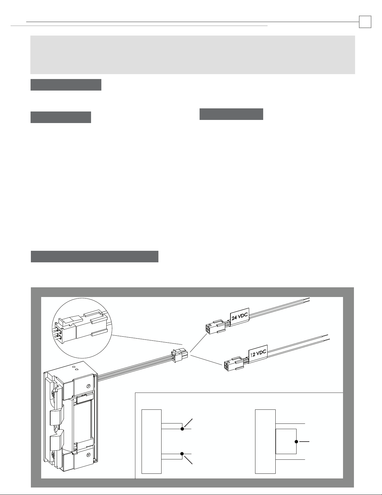
2. Select the appropriate Plug In Connector that matches
system power and electrically connect as illustrated in
Diagram 2. For 12V AC/DC or 16V AC, the pigtail marked “12
VDC” should be used. For 24V AC/DC, the pigtail marked
“24 VDC” should be used. If no connector is present,
configure the wires as illustrated within Diagram 2.
3. Make sure that the electric strike is in correct mode of
operation. This electric strike ships in fail secure mode. If
you need to convert the unit to fail safe, see Diagram 3 on
page 3.
4. If using Latchbolt Monitor (LBM), see Diagram 4.
5. Attach the faceplate to the electric strike, using the #8-32
screws provided. Be sure that the ramps are on top of the
faceplate. (see Diagram 5 on page 3).
Prepare Frame
6. Prepare door jamb per the appropriate template detail
(see pages 4-6).
7. If applicable, install mounting tabs using #10-32 screws.
Do not tighten.
Finish Installing
8. If opening is not plumb and square, see “Read Me” guide
for recommended corrections.
9. Install the electric strike unit in jamb cutout, using
#12-24 screws provided (or wood screws where
necessary).
10. The deadlatch must not interfere with the 8000/8300
ramps (see Diagram 6 on page 3). If you need to adjust the
ramps, mark the centerline of the deadlatch onto the
8000/8300 faceplate. Remove the 8000/8300 electric strike
from jamb. Loosen screws and slide internal ramp until the
groove between the ramps aligns with the mark made on
the faceplate. Tighten the screws. (see Diagram 7 on page
3).
11. Connect wires from power source to the electric strike.
12. Reinstall electric strike, tighten the #12-24 screws and
verify clearance of deadlatch.
13. If applicable, tighten the #10-32 screws holding the
mounting tabs.
DIAGRAM 2: 12V to 24V CONVERSION
IF CONNECTOR IS MISSING
CONNECT
RED
VIOLET
STRIKE
BLACK
ELECTRIC
RED/GREEN
TOGETHER
(+ 12 VDC)
(-NEG)
CONNECT
TOGETHER
RED
VIOLET
STRIKE
BLACK
ELECTRIC
RED/GREEN
(+ 24 VDC)
CONNECT
TOGETHER
(-NEG)
Page 3

Installation Diagrams
3
DIAGRAM 4: LATCHBOLT MONITORDIAGRAM 3: FAIL SAFE TO FAIL SECURE
Loosen screws, but do not
a
remove them
Move screws to the Fail Safe
b
position as shown
Tighten screws
c
Fail Safe*
*Fire rating only applies to Fail
Secure units. Conversion to Fail
Safe negates fire rating on 8300
LBM WIRING
Common
White
Orange Normally Open
Green Normally Closed
White
Orange
Green
DIAGRAM 5: FACEPLATE INSTALLATION
DIAGRAM 6: VERTICAL ALIGNMENT
DIAGRAM 7: VERTICAL ADJUSTABILITY
Centerline
Page 4

Cutout Templates
8000/8300 with 801 Faceplate
1-1/4” X 4-7/8” Square Corner Faceplate
ANSI Metal Jamb Installations
1-1/4" [32]
3-3/8" [86]
4
Inches [mm]
4-7/8" [124]
4-1/8" [105]
1/8" [3]
NOTE: The 8000/8300 electric strike
with 801faceplate will fit right into
most standard ANSI A115.2, 1”
deep dustboxes (e.g. the Curries
®
E-1 preparation), requiring no
cutting.
If you elect to place the 8000/8300
into the existing dustbox, simply
drill for wire connections.
DIAGRAM 8: WIRE DRILLING
3/16" [4.8]
1-1/32” [26.2]
3/8"
[9.5]
3/4" [19]
Diameter
Page 5

Cutout Templates
5
Inches [mm]
8000/8300 with 801A Faceplate
1-1/4” x 4-7/8” Radius Corner Faceplate
Aluminum Jamb Installations
1-1/4"[32]
4-7/8" [124]
4-1/8" [105]
3-3/8" [86]
8000/8300 with 801E Faceplate
1-1/4” x 4-7/8” Faceplate with Extended Lip
‘Knock Down’ Type Jamb Installations
1-1/4"[32]
4-7/8" [124]
4-1/8" [105]
3-3/8" [86]
Snap-On Molding
No Notching
Required
R 5/32" [4]
1/8" [3]
8000/8300 with 802 Faceplate
1-7/16” x 7-15/16” Radius Corner Faceplate
Aluminum and Wood Jamb Installations
1-7/16" [36.5]
Remove additional material as
needed to provide clearance for
electric strike and wires. Then drill
for wires (see Diagram 8)
3-3/8" [86]
7-5/32" [182]
7-15/16" [202]
R 5/32" [4]
1/8" [3]
Page 6

Cutout Template
8000/8300 with 803 Faceplate
1-1/4” x 6-7/8” Radius Corner Faceplate
1-1/4" [32]
3-3/8" [86]
6
Inches [mm]
Aluminum Jamb Installations
6-7/8" [175]
6-1/8" [156]
1/8" [3]
8000/8300 with 805 Faceplate
1-3/8” x 9” Radius Corner Faceplate
Aluminum or Wood Jamb Installations
1-3/8" [35]
Remove additional material as
needed to provide clearance for
electric strike and wires. Then drill
for wires (see Diagram 8)
3-3/8" [86]
1-1/16
9" [228.4]
3068006.003 rev B.
3/32" [2.4]
1/8" [3]
© 2009 HES, Inc.
 Loading...