

Page 1
Installation Instructions
Folger Adam 700 Series Electric Strike
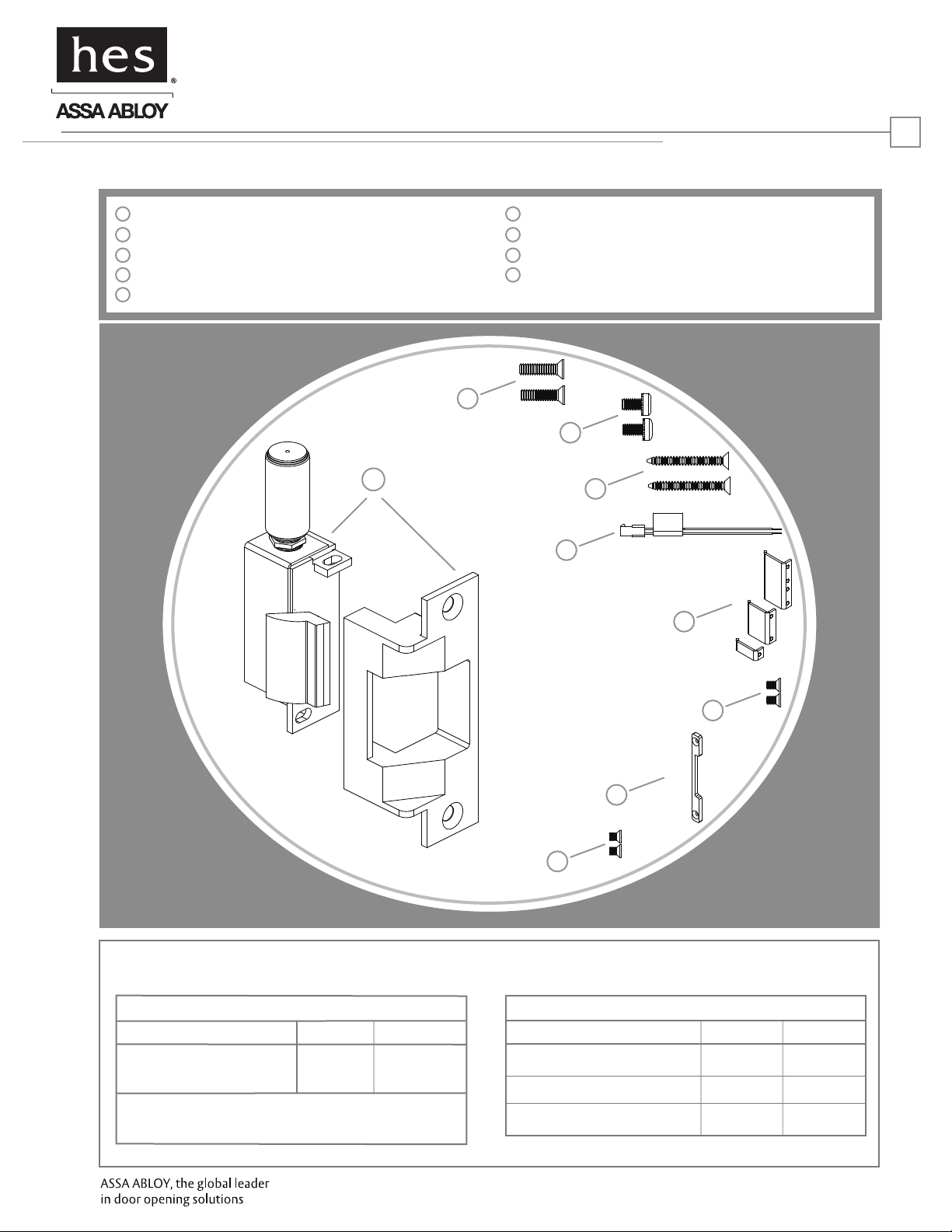
Product Components
HES, Inc.
22630 N. 17th Ave.
Phoenix, AZ 85027
800-626-7590
www.hesinnovations.com
1
1
Electric Strike Body & Faceplate
2
#12-24 Faceplate Mounting Screws
3
#8-32 Body Mounting Screws
4
#12 x 2 1/2” Wood Faceplate Mounting Screws
5
Plug In Connector
1
6
Deadlatch Tabs (742-75 only)
7
#6-32 x 5/16” Deadlatch Tabs Screws (742-75 only)
8
Keeper Shim (742-75 only)
9
#6-32 x 3/16” Keeper Shim Screws (742-75 only)
2
3
4
5
6
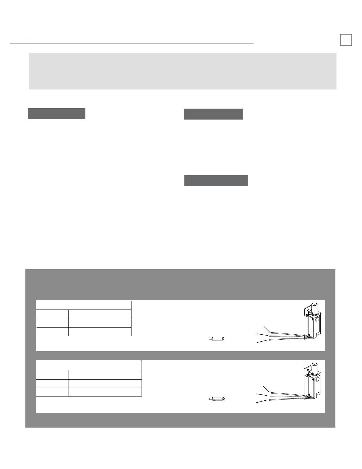
Electrical Specifications
ELECTRICAL RATINGS FOR SOLENOID
CONTINUOUS DUTY
Resistance in Ohms
Amps
12VDC
41
.29
Solenoids are rated at +/- 10% indicated value.
24VDC
160
.15
7
8
9
MINIMUM WIRE GAUGE REQUIREMENTS
SOLENOID VOLTAGE
200 feet or less
200 - 300 feet
300 - 400 feet
12VDC
18 gauge
16 gauge
14 gauge
24VDC
18 gauge
18 gauge
16 gauge
Page 2
Installation Directions
CAUTION! Before connecting any device at the installation site, verify input voltage using a multimeter.
Many power supplies and low voltage transformers operate at higher levels than listed. Any input voltage exceeding
10% of the solenoid rating may cause severe damage to the unit and will void the warranty.
2
Prepare Strike
1. Attach the faceplate to the strike body using the
#8-32 Body Mounting screws as illustrated on page 3,
Diagram 2.
2. If using the LCBLCM (Latchbolt & Locking Cam Monitor),
see Diagram 1 for wiring
instructions.
3. The strike body ships as either a 12 or 24 volt
unit and is not field selectable. Verify the available
voltage is +/- 10% of the rated voltage of the strike body.
Prepare Frame
4. If using a mortise lockset, calculate offset using Diagram
3 on page 3.
5. Prepare frame using the template for your strike
located on pages 4-6. If using the 742-75, see the 742-75
template on page 3 to install the Deadlatch Tab and
Keeper Shim. Note: Drawing shows only one shim.
Finish Installing
6. Connect the Plug In Connector to the electric strike, and
connect wires from the Plug In Connector leads to the
power source.
7. Install the electric strike unit in jamb cutout, using the
#12-24 x 1/2” faceplate mounting screws for metal
applications, or #12 x 2-1/2: wood screws for wood
applications.
Diagram 1: Monitoring Switches
Latchbolt Monitor (LBM)
White
Orange
Green
Locking Cam Monitor (LCM)
Brown
Blue
Yellow
Common
Normally Open
Normally Closed
Common
Normally Open
Normally Closed
White
Orange
Green
Brown
Blue
Yellow
Page 3

Installation Directions
Diagram 2: Faceplate Attachment
To install the 700 series electric strike body to the
faceplate, install two #8-32 Body Mounting screws
as shown. Make sure bolts are tightened and secured.
Keeper position can be adjusted by loosening the #8-32
body mounting screws, and repositioning the strike body
as needed. Retighten body mounting screws after
adjustment is made
3
C
L
Mortise
Door Prep
[101.60]
8”
[203.20]
4”
Diagram 3: Determining Mortise Offset
MORTISE LOCK B
CORBIN/RUSSWIN
ARROW, FALCON
B
BEST 34H-37H 1/4"
SARGENT (8200)
C
L
Strike
YALE (8800)
SCHLAGE
YALE (8700) 7/8"
BEST 45H & 47H* 1/8"
0"
3/16"
3 /4"
*Best 45H & 47H are recommended for
use with the 742-75 only.
Page 4

Cutout Templates
712 Template & Dimensions
Method of install may vary per door & frame manufacturer
1-1/4”
[31.75]
5/8”
[15.88]
4-7/8"
[123.83]
(RHRB APPLICATION SHOWN)
Inches [mm]
1-5/8”
[41.3]
4
3-3/8"
[85.72]
1-1/4”
[31.75]
5/8”
[15.88]
1-1/2"
[38.10]
4-1/8"
4-1/8”
[104.78]
4-7/8”
[123.83]
[104.78]
3-3/8”
[85.72]
1/2”
[13]
1-1/4”
[31.75]
712-75 Template & Dimensions
Method of install may vary per door & frame manufacturer
(RHRB APPLICATION SHOWN)
6”
[152.4]
1/8”
[3.5]
1-1/2”
[38.10]
1-7/8”
[47.6]
3-3/8"
[85.72]
1-1/2"
[38.10]
[123.83]
4-1/8"
[104.78]
4-7/8"
3-3/8”
[85.7]
1/2”
[13]
1-1/4”
[31.8]
4-1/8”
[104.8]
4-7/8”
[123.8]
6”
[152.4]
1/8”
[3.5]
1-1/2”
[38]
Page 5

Cutout Templates
732 Template & Dimensions
Method of install may vary per door & frame manufacturer
1-1/4”
[31.75]
5/8”
[15.88]
[123.83]
4-1/8"
[104.78]
3-3/8"
[85.72]
(RHRB APPLICATION SHOWN)
4-7/8"
Drill 1" Dia. Hole thru,
for wires & solenoid.
C
L
1-5/16”
[26.34]
3-3/8”
[85.72]
1/2”
[12.70]
1-1/4”
[31.75]
4-1/8”
[104.78]
4-7/8”
[123.83]
1-5/8”
[41.3]
1-1/2”
[38.10]
5
Inches [mm]
1-1/4”
[31.75]
5/8”
[15.88]
3-3/8"
[85.72]
1-1/2"
[38.10]
C
L
31/32”
[24.5]
[19.05]
732-75 Template & Dimensions
Method of install may vary per door & frame manufacturer
4-7/8"
[123.83]
4-1/8"
[104.78]
Drill 1" Dia. Hole thru,
for wires & solenoid.
(RHRB APPLICATION SHOWN)
1-5/16”
[26.34]
3/4”
[12.70]
3-3/8”
[85.72]
1/2”
3-5/8”
[92.2]
1-1/4”
[31.75]
4-1/8”
[104.78]
1/8”
[3.5]
4-7/8”
[123.83]
1-7/8”
[47.6]
1-1/2”
[38.10]
1-1/2"
[38.10]
C
L
C
L
31/32”
[24.5]
3/4”
[19.05]
3-7/8”
[98.4]
1/8”
[3.5]
Page 6

Frame Preparation
742-75 Dimensions and Template
4500 WITH SCHLAGE AND YALE MORTISE LOCKS
Method of install may vary per door & frame manufacturer
1-1/4”
[31.75]
5/8”
[15.88]
4-7/8"
[123.83]
(RHRB APPLICATION SHOWN)
3/4"
[18.8]
3/8"
[9.3]
Inches [mm]
Ø
3/4"
[19.1]
1/8"
[3.2]
6
3-3/8"
[85.72]
1-1/2"
[38.10]
4-1/8"
[104.78]
4-7/8"
[123.4]
3-3/8"
[85.7]
9/16"
[14.8]
4-1/8"
[104.8]
5/8"
[15.9]
1-1/4"
[31.5]
6-5/16"
[159.9]
1-15/16"
[49]
1-1/2"
[38.1]
If additional horizontal adjustment is
needed, install the keeper shim using
the #6-32 x 3/16” keeper shims screws
as illustrated.
3831006.001 rev B
Several deadlatch tabs are included for
use with the 742-75. Choose, and position
the deadlatch tab so that the deadlatch is
depressed when the door is closed, while
staying clear of the latchbolt.
Install the deadlatch tab using the
#6-32 x 5/16” deadlatch tab screws as
illustrated.
© 2010 HES, Inc.
 Loading...