

Page 1
Installation Instructions
Folger Adam 310 Series Electric Strike
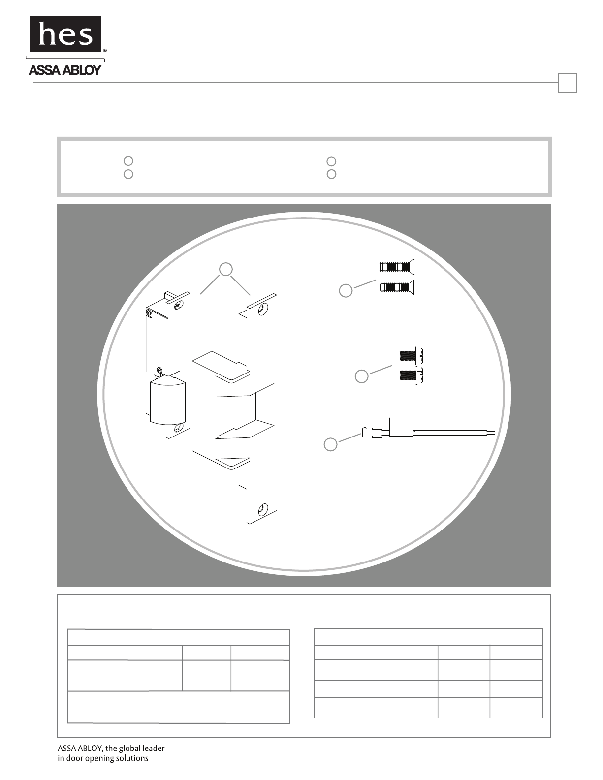
Product Components
1
300 Series Electric Strike Body & Faceplate
2
#12-24 x 1/2” Faceplate Mounting Screws
1
HES, Inc.
22630 N. 17th Ave.
Phoenix, AZ 85027
800-626-7590
www.hesinnovations.com
3
#12-24 x 3/8” Body Mounting Screws
4
Plug In Connector
2
1
Electrical Specifications
ELECTRICAL RATINGS FOR SOLENOID
CONTINUOUS DUTY
Resistance in Ohms
Amps
Solenoids are rated at +/- 10% indicated value.
12VDC
23.5
.51
24VDC
96
.25
3
4
MINIMUM WIRE GAUGE REQUIREMENTS
SOLENOID VOLTAGE
200 feet or less
200 - 300 feet
300 - 400 feet
12VDC
18 gauge
16 gauge
14 gauge
24VDC
18 gauge
18 gauge
16 gauge
Page 2
Installation Directions
CAUTION! Before connecting any device at the installation site, verify input voltage using a multimeter.
Many power supplies and low voltage transformers operate at higher levels than listed. Any input voltage exceeding
10% of the solenoid rating may cause severe damage to the unit and will void the warranty.
2
Prepare Strike
1. Attach the faceplate to the strike body using the #12-24 x
3/8” Body Mounting screws as illustrated on page 3,
Diagram 2.
2. If using the LCBMA (Latchbolt & Locking Cam Monitor),
see Diagram 1 for wiring instructions.
3. The strike body ships as either a 12 or 24 volt
unit and is not field selectable. Verify the available
voltage is +/- 10% of the rated voltage of the strike body.
Prepare Frame
4. If using a mortise lockset, calculate offset using Diagram
3 on page 3.
5. Prepare frame using the template for your strike
located on pages 4-6.
Finish Installing
6. Connect the Plug In Connector to the electric strike, and
connect wires from the Plug In Connector leads to the
power source.
7. Install the electric strike unit in jamb cutout, using the
#12-24 x 1/2” faceplate mounting screws provided.
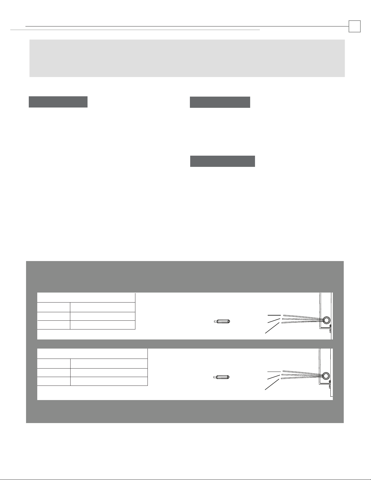
Latchbolt Monitor (LBM)
White
Orange
Green
Common
Normally Open
Normally Closed
Locking Cam Monitor (LCM)
Brown
Blue
Yellow
Common
Normally Open
Normally Closed
White
Orange
Green
Brown
Blue
Yellow
Page 3

Installation Directions
Diagram 2: Faceplate Attachment
To install the 310 series electric strike body to the
faceplate, install two #12-24 body mounting screws
as shown. Make sure bolts are tightened and secured.
Keeper position can be adjusted by loosening the #12-24
body mounting screws, and repositioning the strike body
as needed. Retighten body mounting screws after
adjustment is made
3
C
L
Mortise
Door Prep
[203.2]
8”
4”
[101.60]
Diagram 3: Determining Mortise Offset
MORTISE LOCK B
CORBIN/RUSSWIN
B
ARROW, FALCON
BEST 34H-37H 1/4"
C
L
Strike
SARGENT (8200)
YALE (8800)
SCHLAGE
YALE (8700) 7/8"
BEST 45H & 47H 1/8"
0"
3/16"
3 /4"
Page 4

Cutout Templates
310-2 Template & Dimensions
1-3/8”
[35]
11/16”
[17.5]
9"
[228.6]
8-3/8"
[212.7]
3-3/4"
[95.3]
3-3/4”
[95.3]
1-3/4”
[44.5]
2-5/8”
[66.7]
11/16”
[17.5]
1-3/8”
[35]
8-3/8”
[212.7]
11/16”
[17.5]
5/16”
[7.9]
9”
[228.6]
7-23/32”
[196.1]
21/32”
[16.6]
1-1/2”
[38.4]
1-5/8”
[41.3]
Inches [mm]
5/32”
[3.9]
1/2”
[13]
4
1-3/8”
[35]
11/16”
[17.5]
3-3/4"
[95.3]
1-1/2"
[38.4]
310-2 3/4 Template & Dimensions
5/16”
[7.9]
9"
[228.6]
8-3/8”
[212.7]
11/16”
[17.5]
9”
[228.6]
8-3/8"
[212.7]
3-3/4”
[95.3]
1-3/4”
[44.5]
2-5/8”
[66.7]
15/16”
[23.8]
1-3/8”
[35]
7-1/8”
[180.9]
1-1/4”
[31.8]
2”
[50.8]
5/32”
[3.9]
3/4”
[19]
2"
[50.8]
Page 5

Cutout Templates
310-2 3/4 OB Template & Dimensions
1-3/8”
11/16”
[17.5]
[35]
5
Inches [mm]
5/16”
[7.9]
1-3/8”
[35]
11/16”
[17.5]
3-3/4"
[95.3]
2"
[50.8]
9"
11/16”
[17.5]
8-3/8”
[212.7]
9”
[228.6]
[228.6]
8-3/8"
[212.7]
3-3/4”
[95.3]
2-5/8”
[66.7]
1-3/4”
[44.5]
15/16”
[23.8]
1-3/8”
[35]
310-2 3/4U Template & Dimensions
5/16”
[7.9]
7-1/8”
[181]
1-1/4”
[31.7]
3/4”
[19]
[50.8]
5/32”
[3.9]
2”
3-3/4"
[95.3]
2"
[50.8]
[228.6]
8-3/8"
[212.7]
9"
3-3/4”
[95.3]
1-3/4”
[44.5]
2-5/8”
[66.7]
15/16”
[23.8]
1/2”
[13]
1-3/8”
[35]
8-3/8”
[212.7]
11/16”
[17.5]
9”
[228.6]
7-1/8”
[181]
1-1/4”
[31.7]
3/4”
[19]
[50.8]
5/32”
[3.9]
2”
Page 6

Cutout Templates
310-3-1 Template & Dimensions
1-3/8”
[35]
11/16”
[17.5]
9"
[228.6]
8-3/8"
[212.7]
3-3/4”
[95.25]
[19.16]
1-3/4”
[44.45]
3/4”
8-3/8”
[212.7]
9”
[229.86]
*Deadlock
Block
7-3/64”
[179.2]
6
Inches [mm]
2-3/8”
[60.33]
3-3/4"
[95.3]
2-1/4”
[57.15]
2-1/2"
15/16”
[23.94]
1-3/8”
[34.93]
5/16”
[7.98]
11/16”
[17.6]
1-1/4”
[31.75]
[63.5]
*The deadlock block that depresses the auxiliary latch can be rotated
180° to move the block 1/4” [6.4] higher if necessary. Handing of the
strike can be changed by moving the deadlock block and cavity plug
to the opposite cavities in the face plate.
2-1/2”
[63.5]
5/32”
[3.99]
3810006.001 rev B.
© 2010 HES, Inc.
 Loading...