

HES 1006-605, 1006-605-LBM, 1006-605-LBSM, 1006-606, 1006-606-LBM Installation Instructions
...Page 1
®
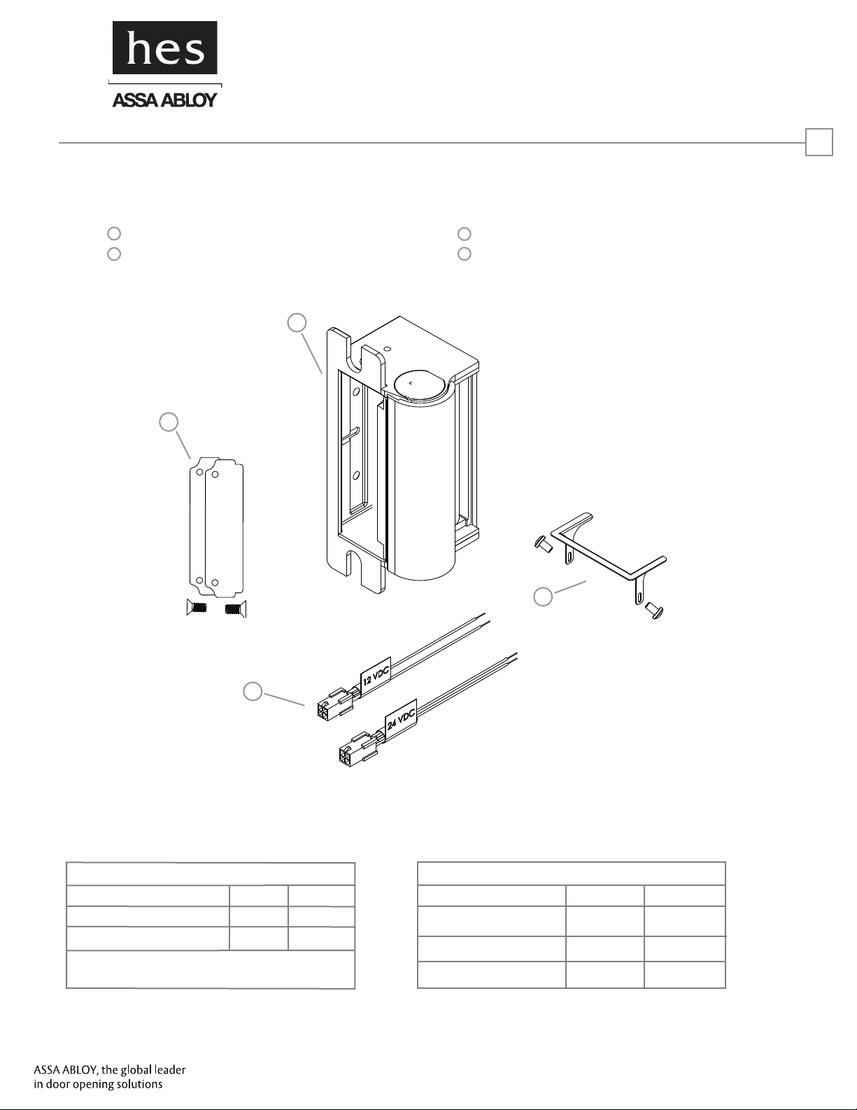
Product Components
1
1006 Electric Strike Body
2
Trim Enhancer (with screws)
1
4
1006 SERIES ELECTRIC STRIKE
Installation Instructions
3
12 & 24 Volt Pigtails
4
Keeper Shims (2, with screws)
1
3
Electrical Specifications
ELECTRICAL RATINGS FOR SOLENOID
CONTINUOUS DUTY
Resistance in Ohms
Amps
Solenoids are rated at +/- 10% indicated value.
12 VDC
25
.48
24 VDC
100
.24
2
MINIMUM WIRE GAUGE REQUIREMENTS (One Way)
SOLENOID VOLTAGE
200 feet or less
200 - 300 feet
300 - 400 feet
12 VDC
18 gauge
16 gauge
14 gauge
24 VDC
18 gauge
18 gauge
16 gauge
3062006.006, Rev. 1
Page 2
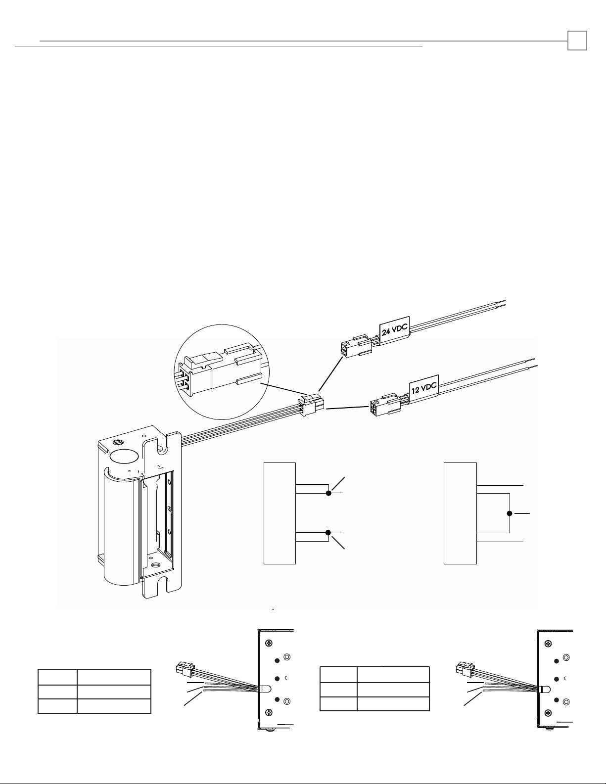
Installation Directions
CAUTION! Before connecting any device at the installation site, verify input voltage using a multimeter. Many
power supplies and low voltage transformers operate at higher levels than listed. Any input voltage exceeding
10% of the solenoid rating may cause severe damage to the unit and will void the warranty.
2
Preparing the Strike
NOTE: For 12V DC, the pigtail marked “12 VDC” should be
used. For 24V DC, the pigtail marked “24 VDC”
should be used.
1. SELECT the appropriate Plug In Connector that matches
system power and electrically CONNECT as illustrated in
Diagram 2.
2. IF no connector is present,
THEN CONFIGURE the wires as illustrated in Diagram 2.
3.
IF using the Latchbolt Monitor (LBM) or Latchbolt
Strike Monitor (LBSM),
THEN REFER to Diagrams 3
and 4 to complete wiring
.
Preparing the Frame
NOTE: Cutout templates are detailed on Page 3 and faceplate
options are detailed on Page 4.
4. PREPARE the frame using appropriate lockset template and
faceplate combination.
Finishing the Installation
5. ATTACH the electric strike to the jamb using the screws
provided with the faceplate option kit.
LBM WIRING
White
Orange
Common
Normally Open
Green Normally Closed
Diagram 3. Latchbolt Monitor Diagram 4. Latchbolt Strike Monitor
White
Orange
Green
IF CONNECTOR IS MISSING
CONNECT
BLACK
VIOLET
STRIKE
RED
ELECTRIC
RED/GREEN
TOGETHER
(+ 12 VDC)
(-NEG)
CONNECT
TOGETHER
Diagram 2. 12V to 24V Conversion
LBSM WIRING
Brown
Blue
Yellow
Common
Normally Open
Normally Closed
Brown
Blue
Yellow
VIOLET
BLACK
STRIKE
RED/GREEN
ELECTRIC
RED
(+ 24 VDC)
CONNECT
TOGETHER
(-NEG)
Page 3
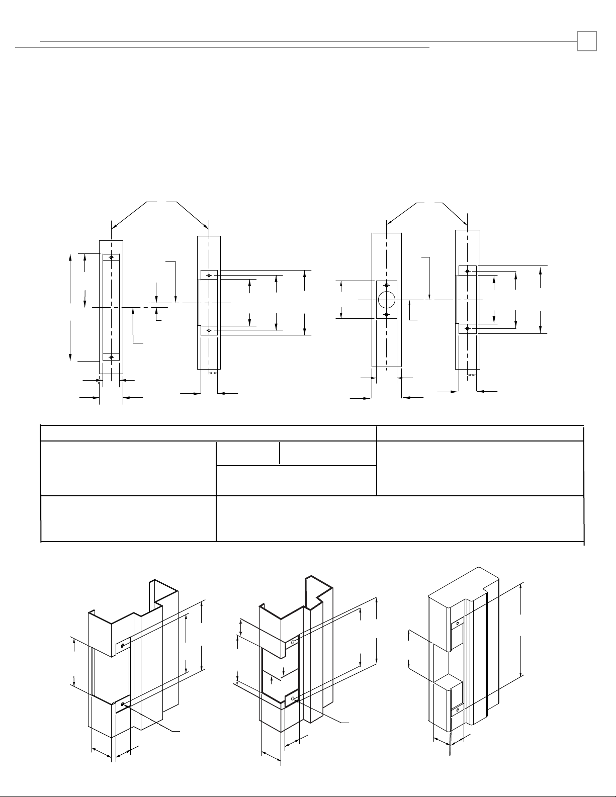
3
Cutout Templates
1006 WITH CYLINDRICAL LOCKSETS
1006 WITH MORTISE LOCKSETS
Please note the horizontal centerline of the electric strike
in relation to the centerline of the mortise lockset.
C
L
Mortise
Lockset
Vertical
Centerline
C
L
Strike
Prep
Strike
4"
[101.6]
4-1/8"
3-1/2"
5/8"
[15.88]
[88.9] [104.77]
8"
[203.2]
1-3/4"
[44.45]
C
L
Lock
1-1/4"
[31.8]
3/8"
[9.53]
1-1/4"
[31.8]
METAL JAMB WOOD JAMB
1006 WITH CYLINDRICAL LOCKSETS
Please note the horizontal centerline of the electric strike
in relation to the centerline of the cylindrical lockset.
C
L
Vertical
Centerline
C
L
STRIKE
C
L
LOCK
1-1/4"
[31.8]
4-7/8"
[123.83]
Cylindrical
Lock
2-1/4"
[57.15]
1-3/4"
[44.45]
Inches [Millimeters]
Strike
Prep
4-1/8"
3-1/2"
[88.9]
[104.77]
5/8"
[15.88]
1-1/4"
[31.8]
4-7/8"
[123.83]
“LB Latchbolt” “DB Dead Bolt” ”AS Deadbolt Recapture” “-2- Latchbolt or Deadbolt”
Cutout dimenstions for option faceplates: Cutout dimenstions for option faceplates: Cutout dimenstions for option faceplates:
J, K, KM, N, NM, H, Z, R and E N, KD, ND, HD, HM, and NM J2, K2, KM2, N2, and H2
Note: Normally used with mortise locks
without deadbolt. Not used with
Schlage L9000 or Yale 8700 series.
Note: Normally used with mortise locks without deadbolt recapture. “AS”
option only used with mortise locks with deadbolt with continuous
recapture. Can be use with Schlage L9000 or Yale 8700 series
Installation for 1006 Series Complete PACs and Faceplate Options
29/32”
3-3/8"
[85.72]
1-11/16"
[42.86]
1-1/4"
[31.8]
4-7/8"
[123.83]
4-1/8"
[104.77]
19/32”
2X 12-24
UNC THREADS
[23.01]
3-3/8"
[85.72]
[15.08]
C
5/32”
C
L
1-11/16"
[42.86]
4-7/8"
[123.83]
4-1/8"
[104.77]
3-3/8"
[85.72]
L
2X 12-24
1-1/4"
[31.8]
UNC THREADS
1-3/8"
[34.92]
1-11/16"
[42.86]
9"
[228.6]
Page 4

Complete Pac Options (continued)
E
4
Components
Low Profile Floor
6-32 x 1/4” Screws
Installation
Deadbolt Catcher
1. Remove the 4-40 x 3/16” screws and standard floor
from the electric strike as illustrated above.
6-32 Nuts
# 6 Lock Washers
4-40 x 5/16” Screw
2. Install the Low Profile Floor using the 4-40 x 5/16”
screw provided with the Faceplate Option Kit as
illustrated above.
Page 5

Complete Pac Options (continued)
H, HD, HM, and H2
5
Components
Deadbolt Bracket
10-32 x 1/8” Screw
Installation
Deadlatch Bracket
(HT and HTD only)
1. Install the Deadbolt Bracket using the 10-32 x 1/8”
screw as illustrated above. If using an HT or HTD option,
proceed to step 2.
# 6 Lock Washers
(HT and HTD only)
6-32x 1/4” Screw
(HT and HTD only)
2. Install the Deadlatch Bracket using the 6-32 x 1/4”
screw and #6 Lock Washer as illustrated above.
Page 6

Complete Pac Options (continued)
R
Components
6
Low Profile Floor
# 6 Lock Washers
4-40 x 5/16” Screw
Hookbolt CatcherHookbolt Bracket
10-32 x 1/8” Screw
Installation
1. Remove the 4-40 x 3/16” screws and standard floor
from the electric strike as illustrated above.
6-32 x 1/4” Screws
2. Install the Low Profile Floor using the 4-40 x 5/16”
screw provided with the Faceplate Option Kit as
illustrated above.
3. Attach the Hookbolt Catcher to the mounting plate
using the 6-32 x 1/4” screws, #6 Lock Washers and the
6-32 nuts as illustrated above.
4. Install the Hookbolt Bracket using the 10-32 x 1/8”
screw as illustrated above. If using an HT or HTD option,
proceed to step 2.
Page 7

7
Faceplate Options
(4-7/8” x 1-1/4” SQUARE CORNER)
HD, ND
“
5/32
[3.97]
3-1/8”
[79.37]
23/32”
[18.26]
KD
C
= center line of faceplate
L
(2nd line = center line of faceplate opening)
H, N
3-1/8”
[79.37]
7/8”
[22.23]
K R
HM, NM
1/8”
[3.17]
Inches [Millimeters]
2-7/8”
[73.02]
1-9/64”
[28.83]
1-1/16”
[26.72]
1-11/32”
[34.11]
23/32”
[18.22]
KM Z
19/32”
[15.46]
1-15/32”
[37.29]
1-3/32”
[27.81]
29/32”
[23.39]
5/16”
[7.79]
1-11/32”
[34.11]
27/32”
[21.46]
1-15/32”
[37.29]
1-25/64”
[35.48]
J, E
23/32”
[18.22]
1-3/4”
[44.45]
27/32”
[21.46]
1-23/32”
[43.64]
1-37/64”
[40.08]
Copyright © 2017, Hanchett Entry Systems, Inc., an ASSA
ABLOY Group company. All rights reserved. Reproduction in
whole or in part without the express written permission of
Hanchett Entry Systems, Inc. is prohibited.
Page 8

8
®
HES, Inc.
Phoenix, AZ 85044
800-626-7590
www.hesinnovations.com
Copyright © 2017, Hanchett Entry Systems, Inc., an ASSA
ABLOY Group company. All rights reserved. Reproduction in
whole or in part without the express written permission of
Hanchett Entry Systems, Inc. is prohibited.
 Loading...