

Page 1
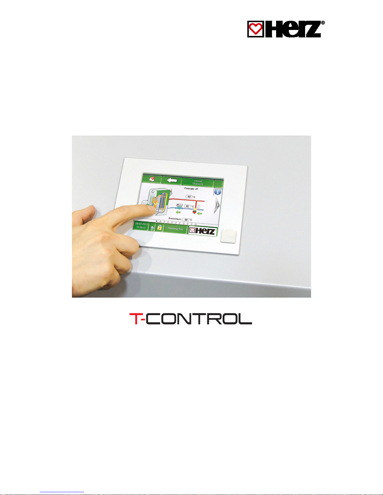
Operating instructions
Cascade control
Page 2

Introduction
2 Bedienungsanleitung Kaskadenregelung T-Control Englisch V1.1
INTRODUCTION
Dear Customer!
Your heating system is powered by a HERZ pelletstar boiler system and we are pleased to be able to count
you as one of our many satisfied owners of a HERZ system. The HERZ boiler is the result of years of
experience and continuous improvement. Please remember that in order to be able to work properly, a welldesigned product also needs to be operated and maintained correctly. We definitely recommend that you
should read this documentation carefully while paying particular attention to the safety instructions.
Compliance with operating procedures is required for any claims made under the manufacturer’s warranty. In
the event of any faults or defects, please contact your heating specialist or the HERZ Customer Service
department.
Yours sincerely
HERZ – Energietechnik
Guarantee / warranty (general)
HERZ boiler systems come with a 5-year warranty on the boiler body, storage tanks and HERZ solar
collectors. We generally guarantee freedom from defects of mobile objects purchased for a period of 2 years,
to a maximum of 6.000 hours of operation. For non-moving purchased items, the guarantee is generally for a
period of 3 years to a maximum for 9.000 hours of operation. Parts subject to wear are excluded from the
warranty/guarantee. Furthermore, claims under warranty will not be applicable if there is no return flow
temperature boost or it is not working properly, if commissioning1 is not carried out by specialist personnel
authorised by HERZ, in the case of operation without a buffer storage tank with a heating load of less than
70% of the rated output (manually stoked boilers must always be operated with a sufficiently dimensioned
buffer storage tank), if hydraulic diagrams2, not recommended by HERZ are used and if a non-prescribed
fuel3, Wood pellets for non-industrial use after ENplus, Swisspellet, DINplus or ÖNORM M 7135 resp. pellets
after EN14961-2; Wood chips after EN 14961-1/4 according to the following specification: Property class A1,
A2, B1 respectively G30, G50 according to ÖNORM M7133 resp. log wood is used.
Any claim to warranty services requires maintenance to be carried out on an annual basis by
specialist personnel authorised by HERZ.
The general warranty period will not be extended if work is carried out under warranty. In the event of a
warranty claim, the due dates for payments owed to us will not be deferred. We will only provide a guarantee
if all the payments owed to us for the product supplied have been made.
The warranty will be carried out at our discretion by repairing the item purchased or replacing any defective
parts, by exchanging the item or by reducing the price. Parts or goods replaced are to be returned to us at
our request free of charge. Wages and costs paid out in connection with installation and removal are to be
paid for by the purchaser. The same applies to all warranty services.
The Supplier shall under no circumstances be liable to the Customer, for any direct, indirect or consequential
costs incurred by the Customer for works carried out on HERZ equipment.
This document is the translation from the German original. The reproduction or copying, even of extracts,
may only be undertaken with the permission of the company HERZ©.
Subject to technical modifications,
Version 04/2014
1
Maintenance by the manufacturer
2
Recommended hydraulic diagrams can be found in the installation manual while hydraulic balancing will be carried out by the heating
contractor
3
Furthermore, the quality of the heating water must be in accordance with ÖNORM H5195 (current version) or VDI 2035
Page 3

Table of content
Bedienungsanleitung Kaskadenregelung T-Control Englisch V1.1 3
TABLE OF CONTENT
Seite
INTRODUCTION ............................................................................................ 2
1
SAFETY NOTES ................................................................................. 4
1.1
Warning notes .................................................................................................................................. 5
1.2
Installation ........................................................................................................................................ 5
1.3
Operation and maintenance ............................................................................................................ 5
1.3.1 General notes ..................................................................................................................................... 5
1.3.2 Operation ............................................................................................................................................ 6
1.3.3 Maintenance ....................................................................................................................................... 6
2
HERZ CASCADE WITH T-CONTROL ................................................. 7
2.1
Extension modules at cascade operation ..................................................................................... 7
2.2
Hardware connections ..................................................................................................................... 7
2.3
Cascade wiring ................................................................................................................................. 8
2.4
Cascade parameters ........................................................................................................................ 9
2.5
Cascade overview ............................................................................................................................ 9
2.5.1 Cascade status ................................................................................................................................... 9
2.5.2 Actual ............................................................................................................................................... 10
2.5.3 Total.................................................................................................................................................. 10
2.6
Master boiler ................................................................................................................................... 10
2.6.1 Manual selection .............................................................................................................................. 10
2.6.2 Change cascade order and prioritization ......................................................................................... 10
2.7
Cascade parameter ........................................................................................................................ 11
2.8
UDP user ......................................................................................................................................... 12
2.9
Fault reports ................................................................................................................................... 12
2.10
Explanation of the symbols .......................................................................................................... 13
3
CASCADE PARAMETER RECOMMENDATION .............................. 13
3.1
Recommended cascade diagrams ............................................................................................... 14
Page 4

1
Safety notes
4 Bedienungsanleitung Kaskadenregelung T-Control Englisch V1.1
1 SAFETY NOTES
Before commissioning, please read the documentation carefully and pay attention to the safety
instructions given in particular. Please consult this manual if anything is unclear.
Make sure that you understand the instructions contained in this manual and that you are sufficiently
informed regarding the way in which the biomass boiler system works. Should you have any queries at
any time, please do not hesitate to contact HERZ.
For safety reasons, the owner of the system must not make any changes to the construction or the state
of the system without consulting the manufacturer or his authorised representative.
Make sure that there is a sufficient supply of fresh air to the boiler room (please heed the relevant
national regulations)
All connections are to be checked before the commissioning of the system in order to make sure that they
are leak-tight.
A portable fire-extinguisher of the prescribed size is to be kept by the boiler room. (Please heed the
relevant national regulations).
When opening the door to the combustion chamber, make sure that no flue gas or sparks escape. Never
leave the combustion chamber door open unattended as toxic gases may escape.
Never heat the boiler using liquid fuels such as petrol or similar.
Carry out maintenance regularly (in accordance with the maintenance schedule) or use our Customer
Service department. (The minimum maintenance intervals specified in the TGPF are to be observed).
When carrying out maintenance on the system or opening the control unit, the power supply is to be
disconnected and the generally valid safety regulations are to be heeded.
In the boiler room, no fuels may be stored outside the system. It is also not permitted for objects which
are not required for the purpose of operating or carrying out maintenance on the system to be kept in the
boiler room.
When filling the fuel bunker using a pump truck, the boiler must always be switched off (this is stamped
on the cover of the filling connection). If this instruction is not heeded, flammable and toxic gases may get
into the storage room!
The fuel bunker is to be protected against unauthorised access.
Always disconnect the power supply if you need to enter the fuel bunker.
Always use low-voltage lamps in the storage room (these must be approved for this type of use by the
relevant manufacturer).
The system is only to be operated using the types of fuel prescribed.
Before the ash is transported further, it must be stored temporarily for at least 96 hours in order to let it
cool down.
Should you have any queries, please call us on +43/3357 / 42840-840.
Initial commissioning must be carried out by the HERZ Customer Service department or an authorised
specialist (otherwise any warranty claim will not be applicable).
Ventilate the pellet storage area for ~ 30 minutes before going in.
The boiler meets the requirements of the Association of Swiss Canton Fire Insurance Companies or
national fire safety regulations. The customer himself shall be responsible without exception for ensuring
that these regulations are complied with on site!
Page 5
Safety notes
1
Bedienungsanleitung Kaskadenregelung T-Control Englisch V1.1 5
1.1 Warning notes
Risk of injury and damage to
property due to improper
handling of the system.
Caution – hot surface
Warning – against hand injuries.
No admittance without
authorisation.
However, adherence to guidelines for
transportation, installation, operation and
maintenance notices as well as technical data (in
the operating instructions, product documentation
and on the equipment itself) which are not
specifically highlighted, is also vital to avoid
breakdowns which may directly or indirectly cause
major personal or material damage.
General note
For reasons of clarity and possible permutations,
this documentation does not contain all detailed
information and cannot take account of every
conceivable operating or maintenance scenario.
Should you require further information or
encounter specific problems, which are not
handled in detail in the documentation supplied,
you can obtain the required information from your
specialist dealer or direct from HERZ.
People (including children) who, because of their
physical, sensory or mental capabilities or because
of their lack of experience or knowledge, are
unable to use the equipment safely must not use
this equipment unless they are supervised or
instructed by a responsible person.
Basic safety information
Due to its functionally limited electrical and
mechanical characteristics with regard to usage,
operation and maintenance, if the equipment is not
able to work according to its appropriate use or
improper interference occurs, it may cause serious
health and material damage. It is therefore
conditional that the planning and implementation of
all installations, transportation, operation and
maintenance will be carried out and supervised by
responsible, qualified persons.
When operating electrical systems, certain parts of
those systems will always carry a hazardous
electrical voltage or be exposed to a mechanical
load. Only appropriately qualified personnel may
carry out work on the system. They must be
thoroughly familiar with the content of this and all
other manuals. In order for this system to function
safely and without any problems, transportation,
storage, operation and maintenance must be
carried out properly and carefully. Instructions and
information on the systems must also be heeded.
1.2 Installation
General notes
In order to ensure that the system will function
properly, the relevant standards and the
manufacturer’s installation instructions are to be
heeded during the installation of the system!
Documents from the manufacturer relating to the
heating devices and components used are
available from HERZ on request.
1.3 Operation and maintenance
1.3.1 General notes
In order for the system to be
operated and maintained safely, it
must be operated and maintained
properly by qualified personnel
while heeding the warnings in this
documentation and the
instructions on the systems.
The system must not be opened
until “HEATING OFF” is displayed
as otherwise there will be a risk of
deflagration (explosion).
Page 6
1
Safety notes
6 Bedienungsanleitung Kaskadenregelung T-Control Englisch V1.1
In unfavourable operating
conditions, the temperatures of
parts of the housing may exceed
80 °C.
If the door to the ash pan is
opened during operation, the fuel
supply will be shut off and the
boiler will switch to the burnout
phase. After that, it will go into the
operating mode “HEATING OFF”.
1.3.2 Operation
General safety instructions
Covers which prevent contact
with hot or rotating parts or which
are required in order to direct the
flow of air correctly and thus
ensure the effective functioning of
the system must not be opened
during operation.
In the event of a fault or unusual
operating conditions such as the
emission of smoke and flames,
the system is to be switched off
immediately by operating the
emergency stop button. The
HERZ Customer Service
department is then to be notified
immediately.
If the main switch is operated on the boiler
room door or if there is a power failure, the
system will be taken out of operation
immediately. The remaining quantity of
residual fuel will burn independently without
giving off any toxic gases provided that the
chimney draught is sufficiently high. Therefore
the chimney must be designed and produced
in accordance with DIN 4705 or EN 13384.
When it is switched on again, the system is to
be checked in order to make sure that it is
fully functional and the safe operation of the
whole system must be guaranteed!
If the residual oxygen content in the flue gas
drops below the minimum of 5% required, the
fuel supply will be stopped automatically and
will not be activated again until the residual
oxygen content has risen to more than 5%
(message displayed: MIN O2 [%] 5.0)
The noise generated by the machine during
operation does not present any danger to
health.
1.3.3 Maintenance
General safety measures
Before starting to carry out any work on the
system, but especially before opening covers
protecting live parts, the system is to be properly
disconnected from the power supply. Besides the
main circuits, attention is also to be paid to any
existing additional or auxiliary circuits in the
process. The normal safety rules according to
ÖNORM are:
Disconnect all poles and all sides!
Ensure that the system cannot be switched on
again!
Check to ensure that no voltage is connected!
Earth and short-circuit!
Cover adjacent live parts and locate
hazardous areas!
These above-mentioned
measures must not be reversed
until the system has been fully
installed and maintenance has
been completed.
Personal dust masks and gloves
must be worn when carrying out
maintenance work in the
combustion chamber or the ash
collector or on flue gas-carrying
parts, when emptying the ash
pan, etc.!
Extra-low-voltage lamps are to be
used when carrying out
maintenance work in the storage
room. Electrical equipment in the
storage room must be designed in
accordance with ÖN M7137!
In order to prevent any maintenance errors, if
maintenance is not carried out properly, it is
recommended for maintenance to be carried out
regularly by authorised personnel or by the HERZ
Customer Service department.
Spare parts must only be obtained directly from the
manufacturer or a distribution partner. The
customer will not be exposed to any health risks as
a result of the noise generated by the machine.
Details on the residual risks can be requested from
the residual risk analysis at HERZ if required.
Page 7
HERZ cascade with T
-
Control
2
Bedienungsanleitung Kaskadenregelung T-Control Englisch V1.1 7
2 HERZ CASCADE WITH T-CONTROL
Herz offers with T-Control the opportunity to cascade 2-8 T-Control modules together. The Cascade contains
boilers of a heating system which can be operated parallel or serial. For example one boiler provides the
basic load of a building and the other remaining boilers are requested at heat requirement (e.g.: e.g.: peak
load boiler or auxiliary boiler). The advantages of a cascade are a higher efficiency of the engaged boilers,
because the boilers are operating under full load as long as possible and an increased operation reliability of
the heating system, because the heat adduction is shared by several boilers. So a higher heating output and
optimized low power output can be assured. At „Master and Slave“-method the cascade guarantees a
constant heating load to the boilers over their lifetime.
2.1 Extension modules at cascade operation
At cascade operation only one boiler can be defined with extension modules like buffer, hot water tank and
heating circuit.
2.2 Hardware connections
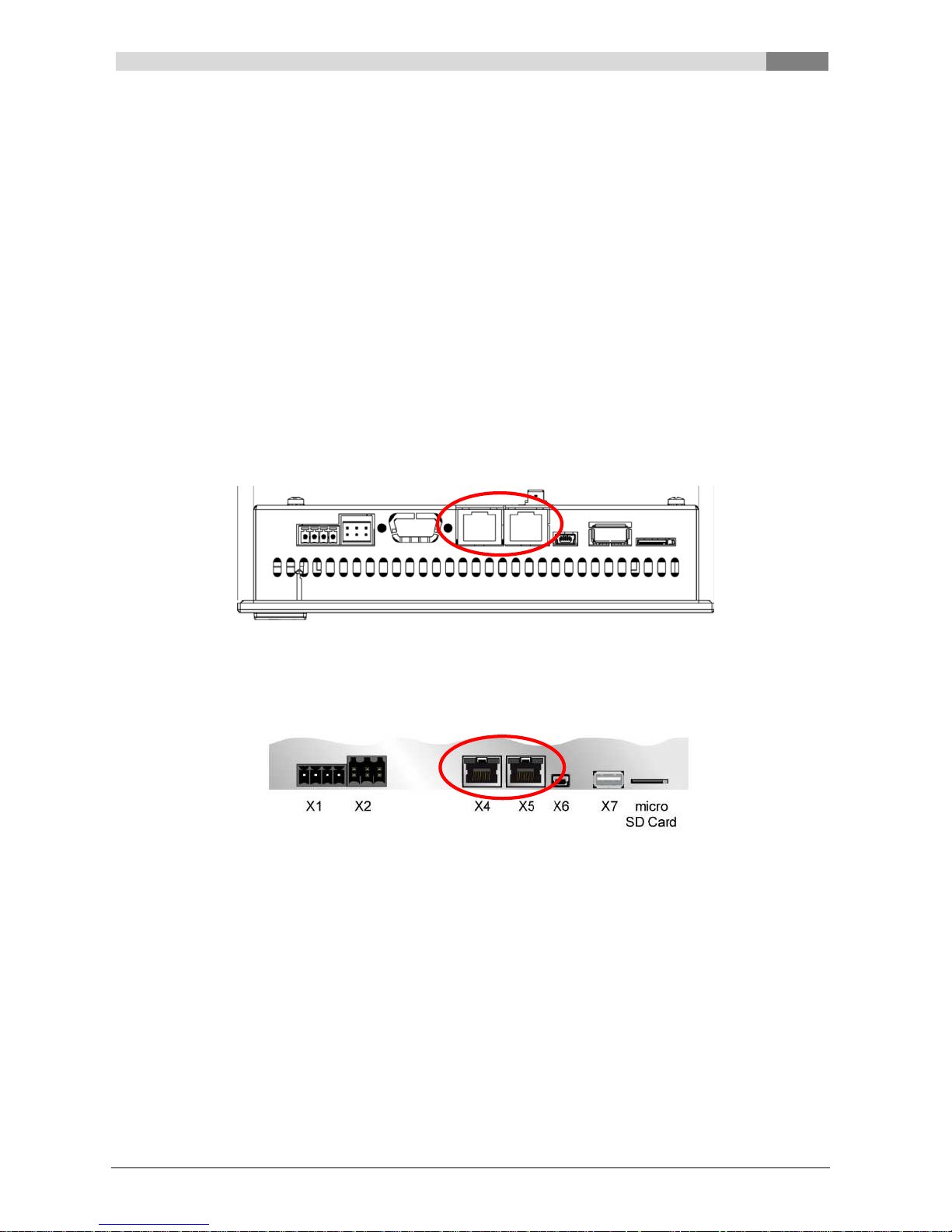
To use the cascade every boiler within has to be extended with terminal HZS 556. The Ethernet pins are
located on the rear side of the terminal (see Figure 2.1).
Figure 2.1 HZS 556 Ethernet pins (rear side)
The terminal HZS 556 comes with to Ethernet pins (see Figure 2.2).
Figure 2.2 X4, X5 Ethernet pins
X4 Ethernet pin for remote control at least CAT5
X5 Ethernet pin for cascade at least CAT5
WARNING - the Ethernet cable has to be provided and wired by customer.
Page 8
2
HERZ cascade with T-Control
8 Bedienungsanleitung Kaskadenregelung T-Control Englisch V1.1
2.3 Cascade wiring
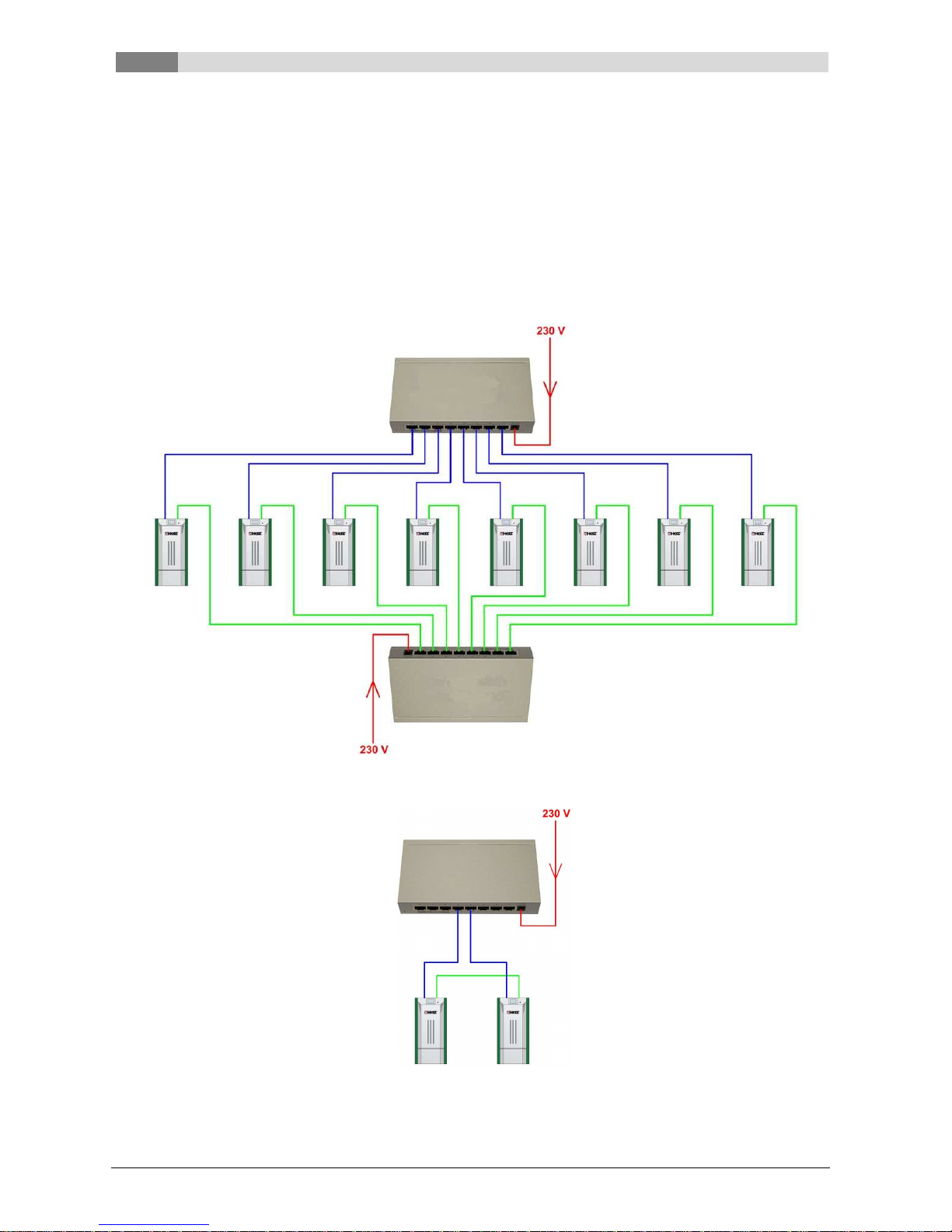
It´s possible to connect 2 to 8 boilers together, using an Ethernet switch and the X5 Ethernet pins. Every
terminal HZS 556 (X5 Ethernet pin) get wired with the Ethernet switch. When using remote control an
additional Ethernet switch has to be used and wired to the terminal HZS 556 X4 Ethernet pin (see
Figure 2.3). If only 2 boilers within a cascade will be used, then no additional Ethernet switch is required (see
Figure 2.4).
At initial order Terminal HZS 556 is factory-made included. If cascade will be ordered later, terminal HZS 556
has to be replaced and Ethernet cable incl. Ethernet switch and power supply must be added. Cascade
wiring (CAT5) has to be installed by customer.
Figure 2.3 3 to 8-Cascade wiring
Figure 2.4 2-Cascade wiring
Ethernet switch
Remote control (to X4)
Ethernet switch
Cascade (to X5)
Ethernet switch
Remote control (to X4)
Page 9
HERZ cascade with T
-
Control
2
Bedienungsanleitung Kaskadenregelung T-Control Englisch V1.1 9
2.4 Cascade parameters
At T-control menu „system settings” in menu „K+“ cascade parameters get set (service code protection).
Cascade parameters have to be set at every cascade user. Push the „K+“ button to get into the cascade
overview.
2.5 Cascade overview
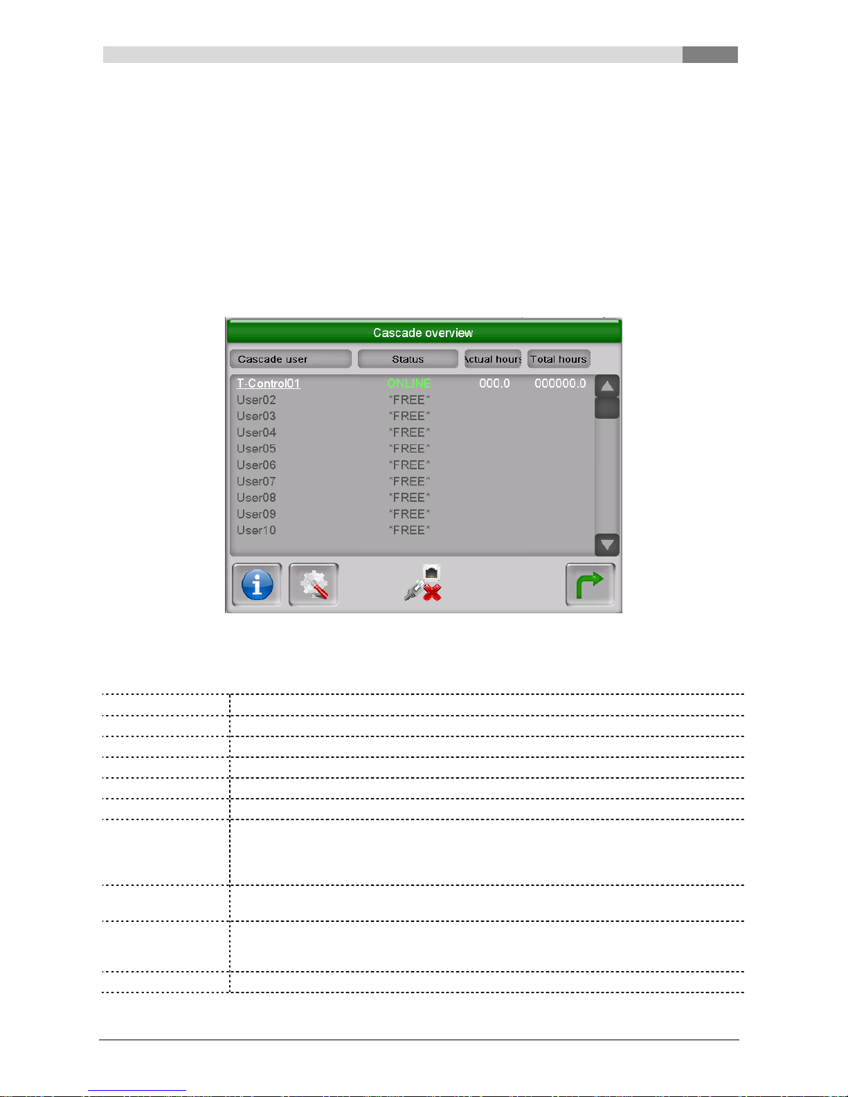
Cascade overview shows every cascade user and its actual status and operating hours within the cascade
(see Figure 2.5).
White displayed cascade users are active, grey are not assigned to the cascade. The actual master boiler is
marked with a star (*). Selected cascade users are shown underlined. Cascade parameter adjustments can
only be done at the respective boiler itself.
Figure 2.5 Cascade overview
2.5.1 Cascade status
OFFLINE
Boiler not available for cascade or data link discontinued
ONLINE
Data link connected, boiler not ready to start (e.g.: boiler off, burn out phase)
READY
Boiler is online and ready to start, boiler ready
START
Boiler starts
OPERATING
Boiler operates
WAITING
Master boiler gets no heat request from heating system
CHANGE
Master Boiler has reached given runtime and query for next prioritized boiler to
assume. As soon as the new master boiler has assumed, status “change” disappears
and boiler gets slave boiler. According to requirements the slave boiler stops or runs
(breath-responsive).
STOP
According to cascade requirements boiler stopped. Status “STOP” will be shown till
burn out phase has ended.
ALARM
Master boiler stopped, or got stopped unexpected. A different boiler within the cascade
get started to assure heat supply. Depending on the actual master boiler status the
status will be shown in the cascade overview.
FREE
No cascade user connected under given ID.
Page 10
2
HERZ cascade with T-Control
10 Bedienungsanleitung Kaskadenregelung T-Control Englisch V1.1
2.5.2 Actual
Master boiler: summarized burning period in hours.
Slave boiler: actual burning period in hours, gets cleared after every restart e.g.: burner cleaning.
2.5.3 Total
Total operating hours within cascade use.
2.6 Master boiler
2.6.1 Manual selection
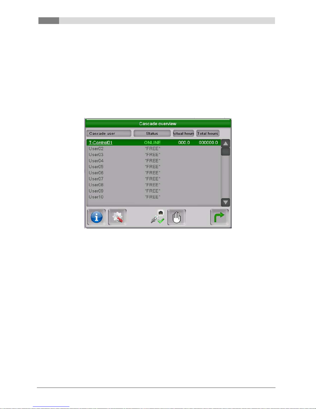
Select underlined cascade user and click hand symbol. Now selected cascade user is the master boiler and
marked with a star (see Figure 2.6).
Figure 2.6 Manual selection and prioritization
2.6.2 Change cascade order and prioritization
The list in cascade overview sets the cascade order, e.g.: which cascade user gets master boiler first.
Choose a not assigned user to set or offset the actual control system (T-Control). Click the saving sign to
save changes. The prioritization of the master boiler within cascade is set by the arrangement 1-X.
Page 11
HERZ cascade with T
-
Control
2
Bedienungsanleitung Kaskadenregelung T-Control Englisch V1.1 11
2.7 Cascade parameter
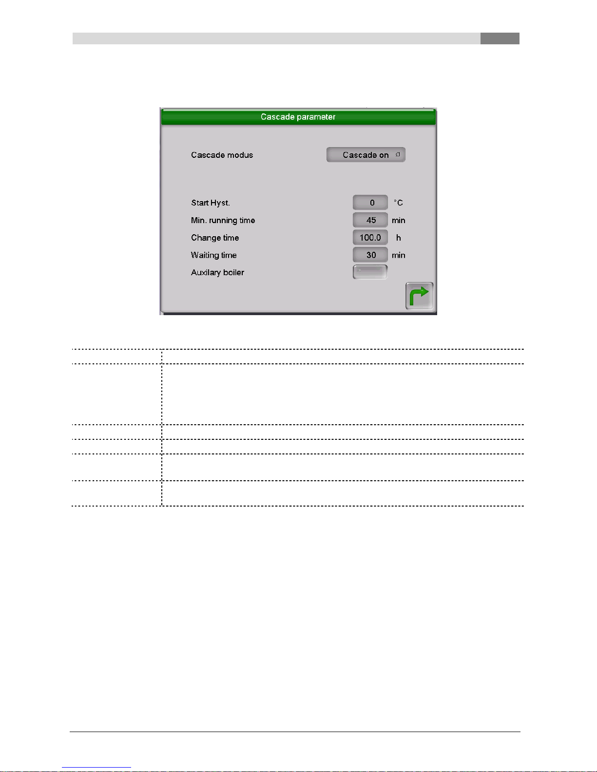
In cascade parameter menu (see Figure 2.7) the cascade parameters for every cascade user will be set.
Figure 2.7 Cascade parameter menu
Cascade modus
Selection of the boiler within the cascade (“Cascade on” or “Cascade off”)
Start Hyst.
If the difference of buffer top temperature to requested temperature of heating systems
with buffer is higher than the start hysteresis, then without await waiting time the
auxiliary boiler gets started.
Exception: start hysteresis = 0 (only waiting time will be active)
At Heating systems without buffer the start hysteresis has to be set to 0
Min. running time
Boiler´s minimal running time within cascade, default value is 45 minutes.
Change time
Burning time (actual) till master boiler will change within cascade.
Waiting time
Waiting time till next boiler will be requested (according to starting hysteresis)
If start hysteresis = 0, only waiting time will be active
Auxiliary boiler
Boiler runs only as slave boiler within the cascade. Boiler will never become a master
boiler. This operation mode is relevant for e.g.: peak load boiler or auxiliary boiler.
Page 12
2
HERZ cascade with T-Control
12 Bedienungsanleitung Kaskadenregelung T-Control Englisch V1.1
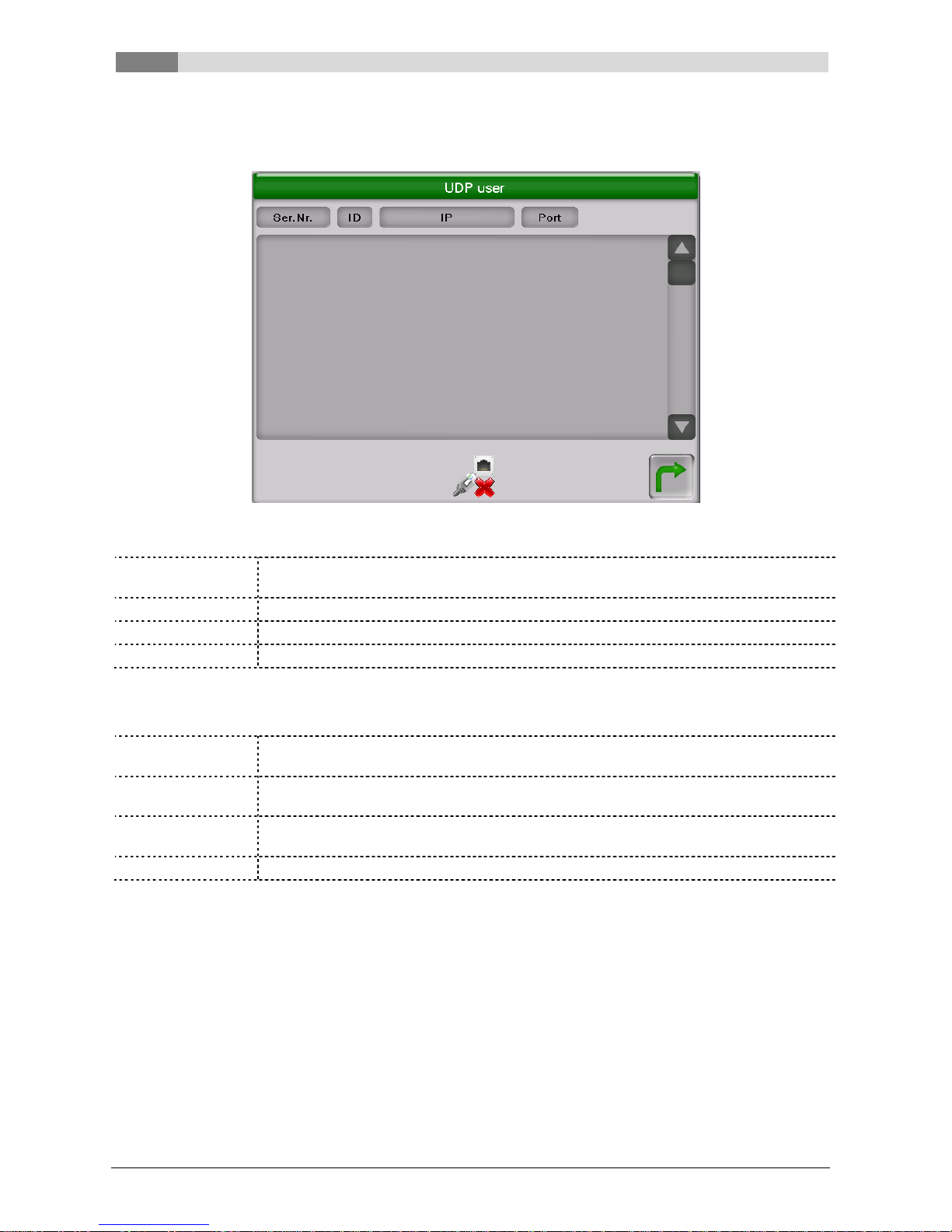
2.8 UDP user
The UDP user menu (see Figure 2.8) shows only the T-Control panels within the cascade.
Figure 2.8 UDP user
Serial Nr.
Shows the serial number of the HZS 566 respectively T-Control panel within the
cascade (unambiguous assignment).
ID
Cascade ID within cascade network.
IP
IP address within cascade network.
Port
Port address, how data gets send (not static).
2.9 Fault reports
KAS OFFLINE
A boiler within cascade is offline (fault report appears at every cascade user). Cascade
overview will show affected boiler.
KAS
CONNECTION
If boiler shows KAS offline, other boilers will show KAS CONNECTION respectively
there is no problem with the connection.
ALARM
A cascade user reports error, so boiler can´t start e.g.: error while starting. When
another boiler is within the cascade, it will take over.
CHECK DATA
Module parameter out of range. Please check module parameters.
Page 13
Cascade parameter recommendation
3
Bedienungsanleitung Kaskadenregelung T-Control Englisch V1.1 13
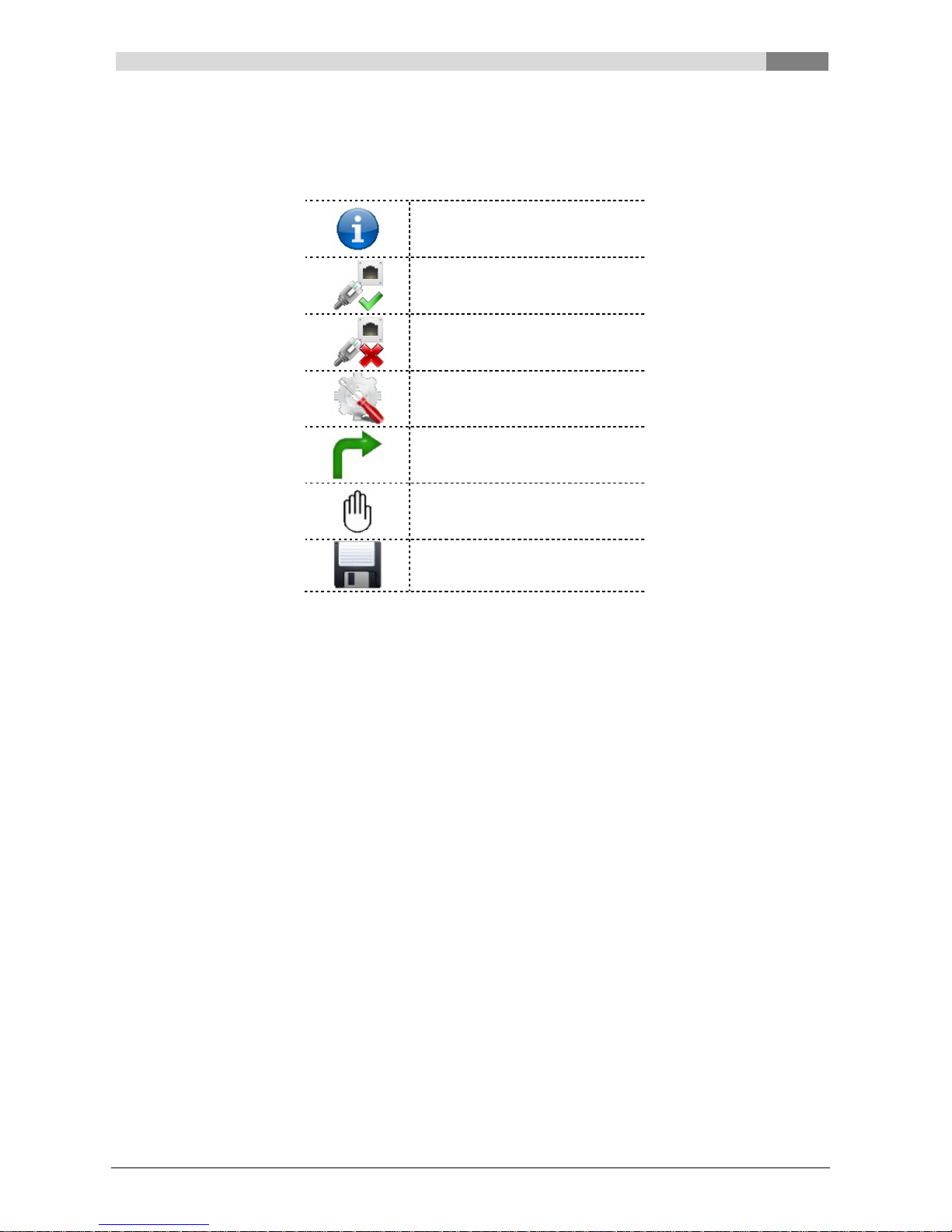
2.10 Explanation of the symbols
Cascade information
Ethernet connection active
Ethernet connection inactive
Cascade parameter access
Back to menu
Manual selection
Save symbol
3 CASCADE PARAMETER RECOMMENDATION
Basically the cascade should be parameterised so that every boiler has almost the same operating hours
within the heating period. That regards especially 2 or more heating systems with identical boiler capacities.
When heating systems with different boiler capacities are installed (basic load boiler, peak load boiler), the
cascade has to be parameterised based on the annual load duration curve. When auxiliary boilers are
provided within the cascade (e.g.: peak load), according to this, they can be addressed.
We recommend to operate cascade heating systems only with buffers.
Page 14
3
Cascade parameter recommendation
14 Bedienungsanleitung Kaskadenregelung T-Control Englisch V1.1
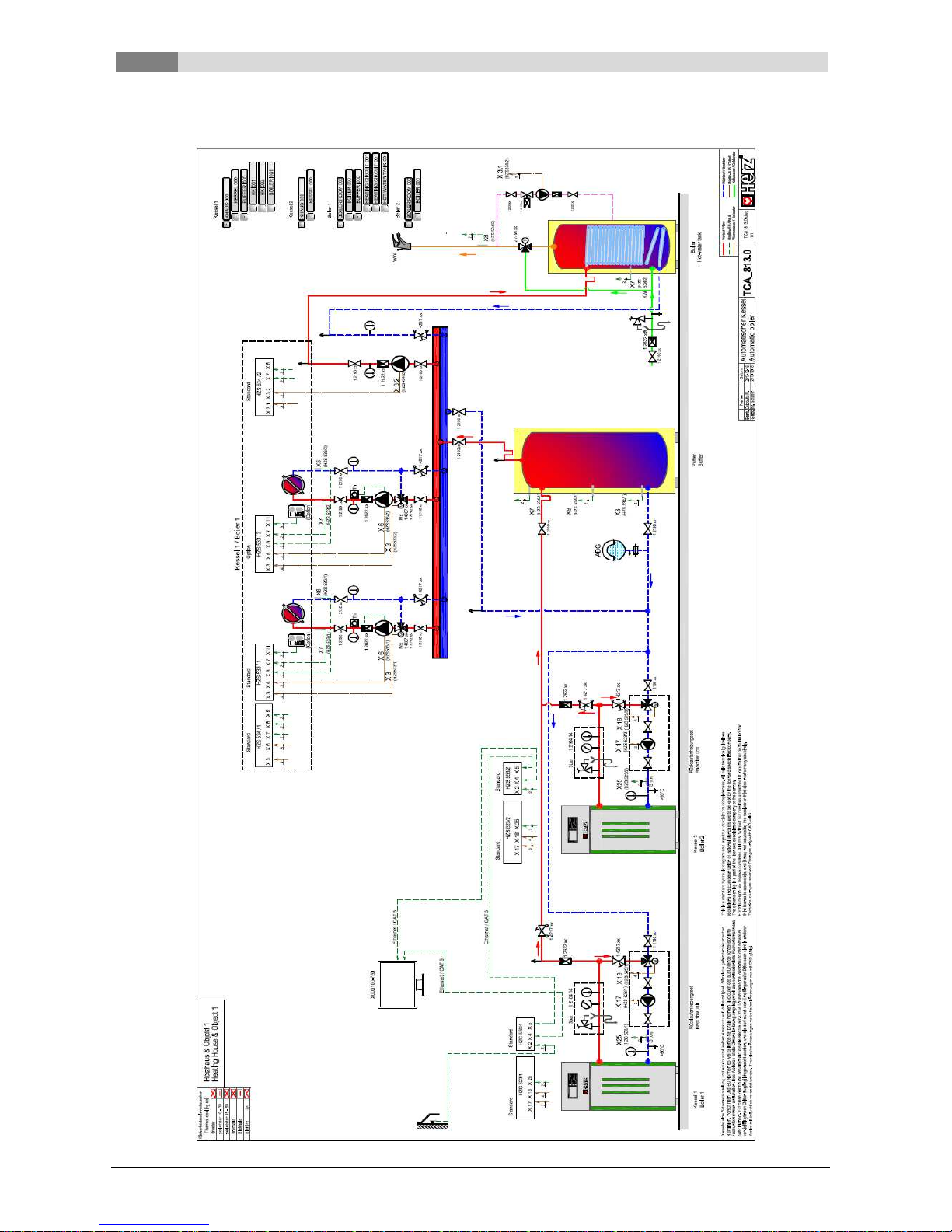
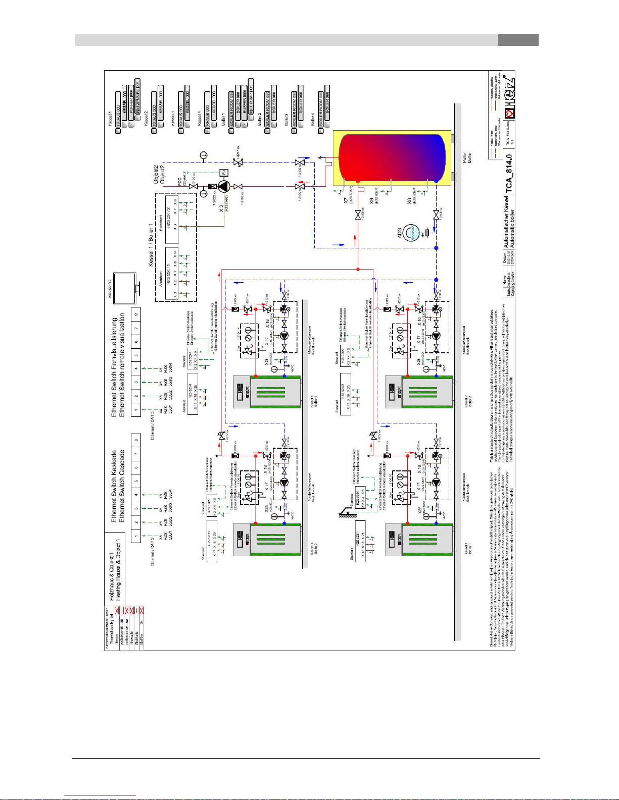
3.1 Recommended cascade diagrams
Page 15
Cascade parameter recommendation
3
Bedienungsanleitung Kaskadenregelung T-Control Englisch V1.1 15
Page 16

Item number:
0000136-301
Österreich/Austria
Version:
V1.1
Herz Energietechnik GmbH
Herzstraße 1
7423 Pinkafeld
+43 (3357) / 42 84 0
– 0
+43 (3357
) / 42 84 0
– 190
office
-
Deutschland/Germany
Herz Armaturen GmbH
Fabrikstraße 76
D-71522 Backnang
+49 (7191) 9021
– 0
+49 (7191) 9021
– 79
verkauf@herz
-
armaturen.de
 Loading...