

Herz pelletstar 10, pelletstar 20, pelletstar 30, pelletstar 60, pelletstar 40 Operating Instructions Manual
...
Operating instructions
pelletstar 10 – 60

Introduction
2 Betriebsanleitung_PS_10_60_Touch_Englisch_V1.3
INTRODUCTION
Dear Customer!
Your heating system is powered by a HERZ pelletstar boiler system and we are pleased to be able to count
you as one of our many satisfied owners of a HERZ system. The HERZ boiler is the result of years of
experience and continuous improvement. Please remember that in order to be able to work properly, a welldesigned product also needs to be operated and maintained correctly. We definitely recommend that you
should read this documentation carefully while paying particular attention to the safety instructions.
Compliance with operating procedures is required for any claims made under the manufacturer’s warranty. In
the event of any faults or defects, please contact your heating specialist or the HERZ Customer Service
department.
Yours sincerely
HERZ – Energietechnik
Warranty / Guarantee (general information)
HERZ boiler systems come with a 5-year warranty on the boiler body, storage tanks and HERZ solar
collectors while electrical components such as electric motors, the control cabinet, ignition devices, etc.
come with a 2-year warranty which starts when the system is first put into operation. Parts subject to wear
are excluded from the warranty/guarantee. Furthermore, claims under warranty will not be applicable if there
is no return flow temperature boost or it is not working properly, if commissioning1 is not carried out by
specialist personnel authorised by HERZ, in the case of operation without a buffer storage tank with a
heating load of less than 70% of the rated output (manually stoked boilers must always be operated with a
sufficiently dimensioned buffer storage tank), if hydraulic diagrams2, not recommended by HERZ are used
and if a non-prescribed fuel3, Pellets (ÖNORM M 7135, DINplus or Swiss Pellets) wood chips (ÖNORM M
7133) resp. log wood is used.
Any claim to warranty services requires maintenance to be carried out on an annual basis by
specialist personnel authorised by HERZ.
The general warranty period will not be extended if work is carried out under warranty. In the event of a
warranty claim, the due dates for payments owed to us will not be deferred. We will only provide a guarantee
if all the payments owed to us for the product supplied have been made.
The warranty will be carried out at our discretion by repairing the item purchased or replacing any defective
parts, by exchanging the item or by reducing the price. Parts or goods replaced are to be returned to us at
our request free of charge. Wages and costs paid out in connection with installation and removal are to be
paid for by the purchaser. The same applies to all warranty services.
The Supplier shall under no circumstances be liable to the Customer, for any direct, indirect or consequential
costs incurred by the Customer for works carried out on HERZ equipment.
This document is the translation from the German original. The reproduction or copying, even of extracts,
may only be undertaken with the permission of the company HERZ©.
Subject to technical modifications,
Version 09/2013
1
Maintenance by the manufacturer
2
Recommended hydraulic diagrams can be found in the installation manual while hydraulic balancing will be carried out by the heating
contractor
3
Furthermore, the quality of the heating water must be in accordance with ÖNORM H5195 (current version) or VDI 2035

Table of content
Betriebsanleitung_PS_10_60_Touch_Englisch_V1.3 3
TABLE OF CONTENT
page page
1 Safety notes ................................... 5
1.1 Warning notes ...................................... 6
1.2 Installation ............................................ 6
1.3 Operation and maintenance ................ 7
1.3.1 General notes ......................................... 7
1.3.2 Operation ................................................ 7
1.3.3 Maintenance ........................................... 7
2 Fuels............................................... 8
2.1 Wood pellets ......................................... 8
3 System ........................................... 9
4 Equipment funtioning ................. 10
4.1 Feeder system .................................... 10
4.2 Type of feed ........................................ 10
4.3 Combustion air control ...................... 10
4.4 Removing the two ash pans .............. 10
4.5 Boiler operation .................................. 11
4.6 Safety devices .................................... 11
4.6.1 Safety temperature limiter STL ............ 11
4.7 Start-up ................................................ 11
4.8 Operating temperatures and
impermissible temperatures ............. 12
4.8.1 Boiler temperature ................................ 12
4.8.2 Return flow temperature ....................... 12
4.8.3 Boiler temperatures that are too high ... 12
4.8.4 Flue gas temperature ........................... 12
5 Operating conditions .................. 13
6 Temperature manager ................. 15
7 Description of the menu
navigation system and settings . 16
7.1 Starting the system ............................ 16
7.2 Main menu ........................................... 17
7.3 Operation and handling ..................... 18
7.4 Explanation of the symbols .............. 18
7.5 Code – entry ........................................ 19
7.6 Switching the boiler on and off ......... 20
7.7 Selecting date and time ..................... 21
7.8 Determining values for the main
menu .................................................... 22
7.8.1 Adding display values to the main menu22
7.8.2 Deleting display values from the main
menu ..................................................... 23
7.9 Fault messages and warnings .......... 24
7.10 Modules ............................................... 25
7.10.1 Boiler ..................................................... 26
7.10.2 Buffer .................................................... 29
7.10.3 Hot water tank ...................................... 31
7.10.4 Heating circuit ....................................... 34
7.10.5 Time mode ............................................ 37
7.10.6 Solar ..................................................... 38
7.10.7 Hydraulic compensator ......................... 46
7.10.8 Net pump .............................................. 47
7.10.9 Zone valve ............................................ 48
7.10.10 External requirement ............................ 49
7.11 Menu settings ..................................... 50
7.11.1 Network configuration ........................... 51
7.11.2 Modbus – settings ................................ 52
7.11.3 Screensaver ......................................... 53
7.11.4 Information overview ............................ 53
7.11.5 Sending e-mails .................................... 54
7.11.6 E-Mail status report .............................. 56
7.11.7 Server – settings ................................... 57
8 Terms and definitions ................. 58
8.1 Boiler module ...................................... 58
8.2 Buffer module ..................................... 64
8.3 Hot water tank module ....................... 66
8.4 Heating circuit module ....................... 69
8.5 Time mode ........................................... 72
8.6 Solar module ....................................... 73
8.7 Hydr. compensator module ............... 75
8.8 Net pump ............................................. 76
8.9 Zone valve ........................................... 77
8.10 External requirement .......................... 77
9 Fault reports and their correction80

Table of content
4 Betriebsanleitung_PS_10_60_Touch_Englisch_V1.3
page
9.1 Faults not indicated on the display
(Maintenance) ..................................... 87
9.2 Maintenance schedule (Customer
inspection) .......................................... 88
10 EC declaration of conformity...... 89
11 Index directory ............................ 90
12 Annex ................................ ........... 91
12.1 Functioning of the operation mode
„Screed drying“ .................................. 91
13 Notes ............................................ 92

Safety notes
1
Betriebsanleitung_PS_10_60_Touch_Englisch_V1.3 5
1 SAFETY NOTES
Before commissioning, please read the documentation carefully and pay attention to the safety
instructions given in particular. Please consult this manual if anything is unclear.
Make sure that you understand the instructions contained in this manual and that you are sufficiently
informed regarding the way in which the biomass boiler system works. Should you have any queries at
any time, please do not hesitate to contact HERZ.
For safety reasons, the owner of the system must not make any changes to the construction or the state
of the system without consulting the manufacturer or his authorised representative.
Make sure that there is a sufficient supply of fresh air to the boiler room (please heed the relevant
national regulations)
All connections are to be checked before the commissioning of the system in order to make sure that
they are leak-tight.
A portable fire-extinguisher of the prescribed size is to be kept by the boiler room. (Please heed the
relevant national regulations).
When opening the door to the combustion chamber, make sure that no flue gas or sparks escape.
Never leave the combustion chamber door open unattended as toxic gases may escape.
Never heat the boiler using liquid fuels such as petrol or similar.
Carry out maintenance regularly (in accordance with the maintenance schedule) or use our Customer
Service department. (The minimum maintenance intervals specified in the TGPF are to be observed).
When carrying out maintenance on the system or opening the control unit, the power supply is to be
disconnected and the generally valid safety regulations are to be heeded.
In the boiler room, no fuels may be stored outside the system. It is also not permitted for objects which
are not required for the purpose of operating or carrying out maintenance on the system to be kept in
the boiler room.
When filling the fuel bunker using a pump truck, the boiler must always be switched off (this is stamped
on the cover of the filling connection). If this instruction is not heeded, flammable and toxic gases may
get into the storage room!
The fuel bunker is to be protected against unauthorised access.
Always disconnect the power supply if you need to enter the fuel bunker.
Always use low-voltage lamps in the storage room (these must be approved for this type of use by the
relevant manufacturer).
The system is only to be operated using the types of fuel prescribed.
Before the ash is transported further, it must be stored temporarily for at least 96 hours in order to let it
cool down.
Should you have any queries, please call us on +43/3357 / 42840-840.
Initial commissioning must be carried out by the HERZ Customer Service department or an authorised
specialist (otherwise any warranty claim will not be applicable).
Ventilate the pellet storage area for ~ 30 minutes before going in.
The boiler meets the requirements of the Association of Swiss Canton Fire Insurance Companies or
national fire safety regulations. The customer himself shall be responsible without exception for
ensuring that these regulations are complied with on site!
1
Safety notes
6 Betriebsanleitung_PS_10_60_Touch_Englisch_V1.3
1.1 Warning notes
Risk of injury and damage to
property due to improper
handling of the system.
Caution – hot surface
Warning – against hand injuries.
No admittance without
authorisation.
However, adherence to guidelines for
transportation, installation, operation and
maintenance notices as well as technical data (in
the operating instructions, product documentation
and on the equipment itself) which are not
specifically highlighted, is also vital to avoid
breakdowns which may directly or indirectly cause
major personal or material damage.
General note
For reasons of clarity and possible permutations,
this documentation does not contain all detailed
information and cannot take account of every
conceivable operating or maintenance scenario.
Should you require further information or
encounter specific problems, which are not
handled in detail in the documentation supplied,
you can obtain the required information from your
specialist dealer or direct from HERZ.
People (including children) who, because of their
physical, sensory or mental capabilities or
because of their lack of experience or knowledge,
are unable to use the equipment safely must not
use this equipment unless they are supervised or
instructed by a responsible person.
Basic safety information
Due to its functionally limited electrical and
mechanical characteristics with regard to usage,
operation and maintenance, if the equipment is
not able to work according to its appropriate use
or improper interference occurs, it may cause
serious health and material damage. It is therefore
conditional that the planning and implementation
of all installations, transportation, operation and
maintenance will be carried out and supervised by
responsible, qualified persons.
When operating electrical systems, certain parts
of those systems will always carry a hazardous
electrical voltage or be exposed to a mechanical
load. Only appropriately qualified personnel may
carry out work on the system. They must be
thoroughly familiar with the content of this and all
other manuals. In order for this system to function
safely and without any problems, transportation,
storage, operation and maintenance must be
carried out properly and carefully. Instructions and
information on the systems must also be heeded.
1.2 Installation
General notes
In order to ensure that the system will function
properly, the relevant standards and the
manufacturer’s installation instructions are to be
heeded during the installation of the system!
Documents from the manufacturer relating to the
heating devices and components used are
available from HERZ on request.
Safety notes
1
Betriebsanleitung_PS_10_60_Touch_Englisch_V1.3 7
1.3 Operation and maintenance
1.3.1 General notes
In order for the system to be
operated and maintained safely, it
must be operated and maintained
properly by qualified personnel
while heeding the warnings in this
documentation and the
instructions on the systems.
The system must not be opened
until “HEATING OFF” is displayed
as otherwise there will be a risk of
deflagration (explosion).
In unfavourable operating
conditions, the temperatures of
parts of the housing may exceed
80 °C.
If the door to the ash pan is
opened during operation, the fuel
supply will be shut off and the
boiler will switch to the burnout
phase. After that, it will go into the
operating mode “HEATING OFF”.
1.3.2 Operation
General safety instructions
Covers which prevent contact
with hot or rotating parts or which
are required in order to direct the
flow of air correctly and thus
ensure the effective functioning of
the system must not be opened
during operation.
In the event of a fault or unusual
operating conditions such as the
emission of smoke and flames,
the system is to be switched off
immediately by operating the
emergency stop button. The
HERZ Customer Service
department is then to be notified
immediately.
If the main switch is operated on the boiler
room door or if there is a power failure, the
system will be taken out of operation
immediately. The remaining quantity of
residual fuel will burn independently without
giving off any toxic gases provided that the
chimney draught is sufficiently high.
Therefore the chimney must be designed and
produced in accordance with DIN 4705 or EN
13384. When it is switched on again, the
system is to be checked in order to make
sure that it is fully functional and the safe
operation of the whole system must be
guaranteed!
If the residual oxygen content in the flue gas
drops below the minimum of 5% required, the
fuel supply will be stopped automatically and
will not be activated again until the residual
oxygen content has risen to more than 5%
(message displayed: MIN O2 [%] 5.0, see
Figure 7.21)
The noise generated by the machine during
operation does not present any danger to
health.
1.3.3 Maintenance
General safety measures
Before starting to carry out any work on the
system, but especially before opening covers
protecting live parts, the system is to be properly
disconnected from the power supply. Besides the
main circuits, attention is also to be paid to any
existing additional or auxiliary circuits in the
process. The normal safety rules according to
ÖNORM are:
Disconnect all poles and all sides!
Ensure that the system cannot be switched
on again!
Check to ensure that no voltage is
connected!
Earth and short-circuit!
Cover adjacent live parts and locate
hazardous areas!
These above-mentioned
measures must not be reversed
until the system has been fully
installed and maintenance has
been completed.
Personal dust masks and gloves
must be worn when carrying out
maintenance work in the
combustion chamber or the ash
collector or on flue gas-carrying
parts, when emptying the ash
pan, etc.!
Extra-low-voltage lamps are to be
used when carrying out
maintenance work in the storage
room. Electrical equipment in the
storage room must be designed in
accordance with ÖN M7137!

2
Fuels
8 Betriebsanleitung_PS_10_60_Touch_Englisch_V1.3
In order to prevent any maintenance errors, if
maintenance is not carried out properly, it is
recommended for maintenance to be carried out
regularly by authorised personnel or by the HERZ
Customer Service department.
Spare parts must only be obtained directly from
the manufacturer or a distribution partner. The
customer will not be exposed to any health risks
as a result of the noise generated by the machine.
Details on the residual risks can be requested
from the residual risk analysis at HERZ if required.
2 FUELS
The HERZ pelletstar – boiler should be operated
with the fuels and their properties which are
described in this chapter.
2.1 Wood pellets
Wood pellets for non-industrial use after ENplus,
Swisspellet, DINplus or ÖNORM M 7135 resp.
pellets after EN14961-2 according to following
specifications:
Property class A1
The maximum permissible fines content in
the fuel store must not exceed 8% of the fuel
volume stored (determined using a
perforated screen with holes 5 mm in
diameter)!
Fines content at the time of loading: <1.0 m-
%
Calorific value in as-delivered condition > 4.6
kWh/kg
Bulk density BD in as-delivered condition >
600 kg/m³
Mechanical Strength DU, EN 15210-1 in as-
delivered condition, m-%: DU97.5 ≥ 97.5
Diameter 6mm
The nominal power and the emission values can
be guaranteed up to a maximum water content of
25 % and a minimum calorific value of 3.5 kWh/kg
of the permissible fuel.
From a water content of about 25% and a calorific
value <3.5kWh/kg a reduced output is expected.
Foreign bodies such as stones or metal
particles should be prevented from entering
the system! Sand and soil lead to more ash
and slagging.
According to the fuel there may be a formation of
slag, which may need to be removed by hand.
In the case of non-compliance, any warranty
or guarantee will be rendered null and void.
The burning of unsuitable fuels could lead to
uncontrolled combustion. Operational faults
and consequential damage are likely to occur.
Is a different fuel on the order named and explicit
on the order confirmation noted, the system can
also be operated with this fuel.
Note: The system is set to the agreed fuel at the
commissioning. This setting (fan speed settings,
fuel settings, flow/backflow fan, cycle time, and so
on) should not be changed by constant fuel
quality.
System
3
Betriebsanleitung_PS_10_60_Touch_Englisch_V1.3 9
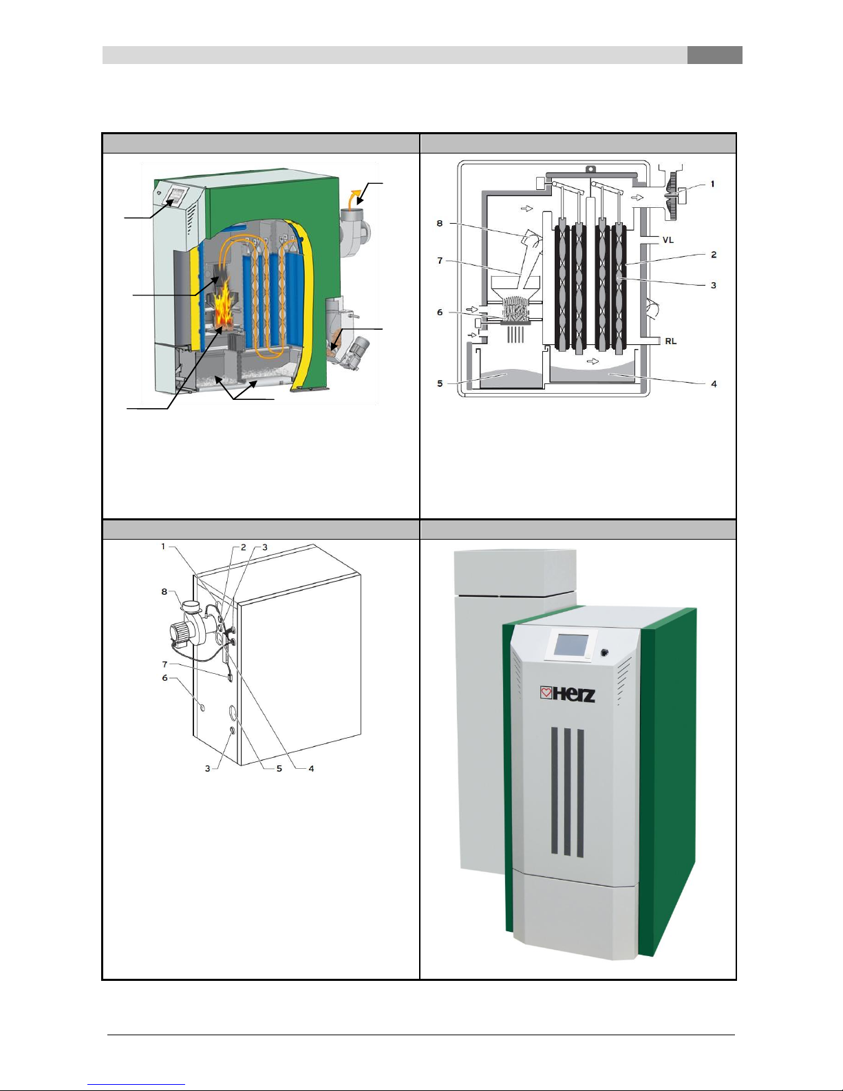
3 SYSTEM
3D view from the side
Side view
Legend
Legend
1 … Induced-draught fan
1 … Induced-draught fan
7 … Filling shaft
2 … BSD feed screw
2 … Heat exchanger
8 … Feed screw
3 … Ash pans
3 … Turbulators
VL .. Heatinf feed flow
4 … Burner
4 … Rear ash pan
RL .. Heating return flow
5 … Pellet inlet
5 … Front ash pan
6 … Operating display
6 … Burner
3D view of the boiler from the back
Boiler with intermediate container
Legende
1 … Bushing for feed connection
2 … Bushing for flue pipe for temperature sensor
3 … Cable bushing for electrical connections
4 … Bushing for return connection
5 … Feed screw opening for screw feed system
Return air hose opening for suction feed system
6 … Bushing for fill and drain valve
7 … Connection to the power supply (additional
electrical connections are required for a screw
feed system)
8 … Induced-draught fan
1 2 3 4 5
6
4
Equipment funtioning
10 Betriebsanleitung_PS_10_60_Touch_Englisch_V1.3
4 EQUIPMENT
FUNTIONING
4.1 Feeder system
The fuel is transported from the fuel storeroom by
means of a feeder screw with flat spring stirrer for
burnback protection devices. It then passes
through the drop shaft and the burnback
protection device. The burnback protection device
is driven by a spring-loaded servo-motor. If the
servo-motor has no power supply then the flap
closes independently. Then the plug-in screw
feeds the fuel upwards. These are then directed to
the combustion chamber via a drop level. The fuel
level reached is crucial for the boiler capacity and
the operating condition of the equipment.
4.2 Type of feed
The operation of the pelletstar based on a pulseno-pulse ratio which controls the feed system. All
the values are to be set via the menu “Fuel
values” (only available in the service area). These
feed values are corrected by the combustion
control system.
4.3 Combustion air control
Differentiation is made between primary and
secondary air (1+2) in the combustion air
supplied. The primary air is supplied directly into
the embers. Using secondary air an attempt is
made to fully develop the flame arising from the
primary air. The air supply is supplied via a lateral
opening (underneath the lateral panelling).
The flue gas ventilator is a suction fan and this is
located at the back of the boiler. It generates low
pressure in the boiler. The secondary and the
primary air are sucked out by this low pressure.
The blower is time-controlled by the variablespeed electronic control. The blower speed is
controlled according to the boiler temperature and
rectified by the lambda control.
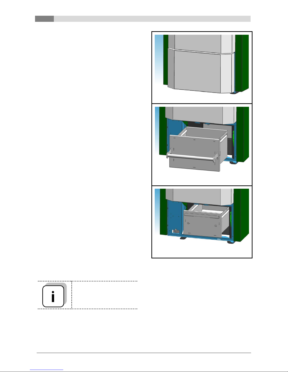
4.4 Removing the two ash pans
Only for pelletstar 45 – 60
Open the ash pan door
You can then take out the first ash pan (at the
front)
The second ash pan is removed by using the
hook provided

Equipment funtioning
4
Betriebsanleitung_PS_10_60_Touch_Englisch_V1.3 11
4.5 Boiler operation
The equipment goes into operation automatically
when heat is required due to its built-in automatic
ignition.
The heat requirement can be weather-driven, and
can be used in conjunction with a remote sensor
(optional) from any heating circuit. It is also
possible to generate demand using a room
thermometer. The boiler can also switch on the
equipment via its heat requirement.
The control or local data of the boiler capacity can
be adjusted or changed.
The regulation prevents boiler temperatures falling
too low as this can affect the life expectancy of the
boiler.
Boiler temperatures that are too high are not
permitted for operational safety reasons.
Any elongation fissures on the insulation plates or
combustion chamber bricks do not affect their
functioning and therefore do not represent a claim
against the guarantee.
4.6 Safety devices
These must be dimensioned and installed to
conform to ÖN B8133.
The safety valve in the boiler circulation serves as
a safety last resort against malfunctions of the
equipment.
All legal safety regulations must be adhered to onsite via the authorised specialist company. All
legal safety regulations must be adhered to onsite via the authorised specialist company.
Earthing or potential equalisation must be carried
out on the machinery for the whole heating
system according to EN 60204-1 by an authorised
specialist company.
4.6.1 Safety temperature limiter STL
Should the boiler temperature exceed 95°C, the
equipment must be switched off for safety
reasons. The safety temperature limiter locks in
this event.
Possible causes may be:
Performance decrease in the boiler was
interrupted abruptly. This can occur due to
the switching off of a pump or sudden
shutting of the heating circuit mixer.
The load pumps are being controlled by the
HERZ Control. The so-called excess
temperature flue gas would be automatically
activated by the HERZ Control. This avoids
higher boiler temperatures.
The boiler is too large.
The fuel level is set too high.
Loss of power supply
Etc.
Firstly the cause of the failure must be found and
corrected and only then can the safety
temperature limiter be unlocked.
The boiler temperature must be under 75°C
before unlocking.
Only after this can the malfunction be rectified. To
do this the covering of the safety temperature
limiter must be unscrewed. Through gentle
pressure using a sharp object the safety
temperature limiter can be unlocked again. After
the cover unscrewed the rectification of the fault
must be carried out via the control box. The safety
temperature limiter is located right from the
operating terminal.
4.7 Start-up
The first start-up must be carried out by HERZ
factory customer service or an authorised
specialist (Otherwise the guarantee becomes
invalid).
Besides this the low pressure in the flue pipe
connecting piece of the boiler is measured after
firing with the designated solid fuels at least one
hour during running time and an advance flow
temperature of 70-85°C is achieved.
It can thereby be determined whether feed
pressure for the correct operation of the boiler
(formerly described as draw requirement“) has set
itself. If the existing chimney has not been
measured correctly or if the calculated chimney
values have not been met (inappropriate
connection, entry of secondary air, connection
piece too long, etc.) deviating values will result
and it will not be possible to operate the boiler
correctly.
During start-up and handover to the operator, the
functioning of all control and safety equipment
must also be monitored and the operation and
maintenance of the boiler and equipment must be
explained to the operator in detail.
The hydraulic balancing of the equipment (pipe
installation) must be carried out by an authorised
specialist company (installer). It is also the duty of
the installer (according to ÖNORM 12170) to
create documentation for the complete system
and this must be deposited in the boiler room.

4
Equipment funtioning
12 Betriebsanleitung_PS_10_60_Touch_Englisch_V1.3
4.8 Operating temperatures and
impermissible temperatures
4.8.1 Boiler temperature
The HERZ pelletstar boiler is operated at a boiler
temperature between 65 und 90°C. If the return
flow temperature is below 55°C some of the flue
gases condense on the inside of the boiler. When
the boiler is started up, the operating temperature
(from 65 to 90°C) must therefore be reached as
quickly as possible in order to avoid condensation.
The return flow temperature may also be under
the permissible value at correct boiler operating
temperature. This condition should be avoided by
a functioning increase in return flow temperature
(at least 55°C, or preferably 60°C).
Note!
All guarantee or warranty claims are invalidated in
the event of damage from corrosion arising due to
impermissible operation temperatures.
4.8.2 Return flow temperature
The return flow temperature must increase to over
55°C (60°C) as quickly as possible, depending
upon the type of boiler. Retention of the
temperature level for the return flow or the boiler
temperature is achieved using a so-called return
flow bypass or return flow temperature
maintenance. In this the advance flow water, for
example, is admixed via a pump and the
appropriate valve.
The heat energy of the boiler can only be used
from the time that the return flow temperature has
exceeded 60°C.
4.8.3 Boiler temperatures that are too
high
The HERZ pelletstar boiler can be operated up to
a maximum boiler temperature of 90°. If the
performance of the boiler is suddenly reduced
(mixers shut off, hot water tank load pump
switches off) it is sometimes the case that the
saved heat energy in the boiler heats up the
heating water above this value.
In the pelletstar equipment there are three safety
measures installed in order to prohibit a further
increase in temperature:
Excess temperature outlet (above 92°C boiler
temperature)
From this temperature the consumer pump is
switched on in order to divert the excess heat
energy. To do this, the loads are set to their
maximum value. The precondition for this is
that these are controlled using HERZ
controls. Should this not be the case then
there is a greater probability that the boiler
will overheat and result in a breakdown.
Thermal flow protection
No thermal overload safety device is required
for the PS 10, 20 and 30 systems. Pelletstar
45-60 systems have a safety heat exchanger
installed in the boiler to which a thermal
overload safety device must be connected.
Safety temperature limiter – STL (above
95°C boiler temperature)
The equipment is switched off above this
temperature. The safety temperature limiter
locks itself and the equipment operation. A
breakdown is indicated and the equipment
stops.
4.8.4 Flue gas temperature
The flue gas temperature depends upon the
operating condition of the equipment, the fuel, the
ventilator setting and the type of boiler.
Therefore applies:
The chimney must not be sensitive to moisture
and must be calculated and dimensioned
according to DIN 4705 or EN 13384. HERZ does
not carry out chimney calculations. This
calculation must be carried out by an authorised
specialist company. A chimney that is incorrectly
designed may lead to malfunction of the
equipment.

Operating conditions
5
Betriebsanleitung_PS_10_60_Touch_Englisch_V1.3 13
5 OPERATING
CONDITIONS
Heating off
In this condition the equipment is switched off, i.e.
the burner is blocked.
Ready
The boiler or buffer temperature is sufficient to
sustain the loads or the boiler temperature has
reached the switch-off temperature.
Prepare ignition
In this condition the grate has been cleaned and
the lambda probe pre-heated.
Pre-ventilate
This condition serves to flush the combustion
chamber and the chimney with air.
Cold start
If the boiler room temperature is below the boiler
room ignition identifying temperature (standard
150 °C), a cold start is carried out. Materials are
pushed in at intervals. At the same time the
material is ignited by the ignition fans. During the
ignition phase there is a check as to whether the
ignition was successful.
After successful ignition, the equipment changes
over to the burning phase. At the same time the
final ignition fan phase is carried out. During the
final ignition fan phase the ventilator of the ignition
fans runs for a minute longer in order to cool down
the heating element.
Should there be no ignition in the maximum
ignition period (3 x the set time) then the
equipment is switched off using the remote status
signal => F: IGNITION (see Error 66)
Scorch phase
This phase serves to achieve an even fire bed.
The length of the phase is set in the fuel values
(only in the service area available). Care should
be taken here that combustion takes place with a
higher surplus of oxygen. This serves to achieve
the desired even fire bed more quickly. This
phase should not be set for longer than 5 minutes.
Run up phase
In the run up phase the equipment runs at rated
output. When the boiler temperature is reached it
then goes over to the control phase.
Control phase
In this phase the boiler is modulated between
nominal load and partial load. When the partial
load stage generates too much energy, i.e. the
target boiler temperature + regulation hysteresis
are exceeded and are then changed to the ready
condition.
Burn out phase
When the boiler switches off, then the fuel
remaining in the combustion chamber is burnt out.
Care should be taken here that this time is set
exactly, as otherwise it is possible that material
present in the combustion chamber will not be
burnt correctly.
Burner cleaning
During burner cleaning the burner is cleaned of
ash. Firstly the fuel is burnt out. When the burnout
time is completed, then the burner plate is
cleaned. After successful cleaning the equipment
goes back into normal mode. The interval is
calculated via the runtime of the plug-in screw.
This can be set via the “Cleaning interval”
parameter in the service area, i.e. in order to
achieve more frequent cleaning of the combustion
chamber the parameter simply has to be
shortened.
Heatexchanger cleaning
Heat exchanger cleaning serves to increase the
degree of efficiency. Here the heat exchanger is
automatically cleaned and the fly ash falls into the
so-called fly ash chamber. The interval and
duration of the cleaning can be set in the service
area via the “HEC INTERVAL” or “HEC
DURATION”.
Output control
The output control is controlled within the boiler
target temperature and the control end phase.
The control end phase is the boiler target
temperature + control hysteresis. When the
control end phase is reached the equipment goes
to burnout.
Flue gas temperature control
When the maximum flue gas temperature is
exceeded, then the output of the equipment is
reduced. If the temperature is not reached the
equipment goes back to normal output control.
Flame monitoring
Where the combustion values fluctuate too greatly
during operation, this is detected and the
equipment is switched off.

5
Operating conditions
14 Betriebsanleitung_PS_10_60_Touch_Englisch_V1.3
Frost protection
When the equipment goes into frost protection
then the return flow bypass pump is switched on
provided that the equipment is in “HEATING OFF”
or “BURNER STOP” condition. Otherwise the
equipment is started up and started up to a
minimum temperature of 65°C.
Lambda control
The amount of material and the suction ventilator
are controlled via the lambda control. This serves
to optimise the combustion and can detect slight
fuel fluctuations. Therefore, it is not necessary to
re-set the combustion after the silo is filled.
Temperature manager
6
Betriebsanleitung_PS_10_60_Touch_Englisch_V1.3 15
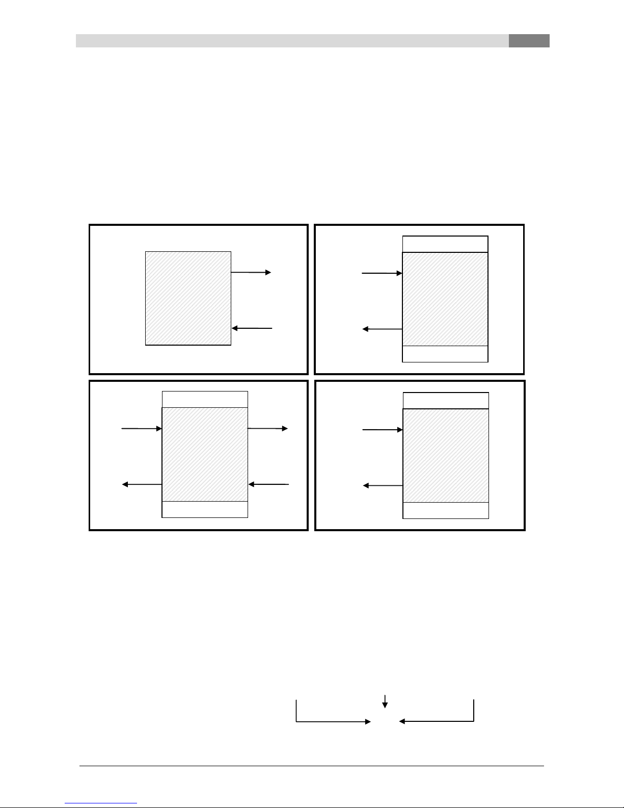
6 TEMPERATURE MANAGER
The control of the heat demands of the individual modules (=heating circuits) happens with a so-called
temperature manager. To understand the operation of the temperature manager the scheme which is
illustrated in Figure 6.1 is used. It can be seen that a module has inputs and outputs. The module gives a so-
called temperature demand to his “heat supplier”. This temperature demand is the sum of an internal
calculated temperature demand and an adjustable temperature increase. The heat supplier must provide this
temperature demand to the modules.
The heat supplier (= heat generator resp. boiler/buffer) which gets the information’s of the temperature
demand of the modules must provide heat to the individual modules. Thereby the maximum of the
temperature demands of the individual modules is generated. These modules will receive the existing
temperature.
Example:
Heat supplier = Boiler
Module 1 & 2 = Heating circuit 1 & 2
Heating circuit 1
Heating circuit 2
Buffer
calculated required temperature in °C
60
30
75
Temp. increase in °C
5 3 0
Required temperature of the
modules in °C
65
33
75
Required temperature
(=maximum formation)
75
Module 2
(Consumer)
Temp.existing
Temp.required
+ Temp increase
OUTPUTS
INPUTS
Buffer
Temp.existing
OUTPUTS
INPUTS
Temp.existing
Temp.required
Module 1
(Consumer)
Temp.existing
Temp.required
+ Temp increase
OUTPUTS
INPUTS
Heat supplier
(Boiler)
Temp.existing
Temp.required
Temp.required
+ Temp increase
Figure 6.1: Temperature manager
7
Description of the menu navigation system and settings
16 Betriebsanleitung_PS_10_60_Touch_Englisch_V1.3
7 DESCRIPTION OF THE MENU NAVIGATION SYSTEM AND
SETTINGS
In this chapter all menu pictures are shown, which occur on the Touch-display. The individual terms, which
are visible on these menu pictures, are explained in chapter 8 – Terms and definitions (starting on page 58).
To find a term and its explanation, the pictures are labelled. The same labelling is also shown in chapter 8 –
Terms and definitions (starting on page 58).
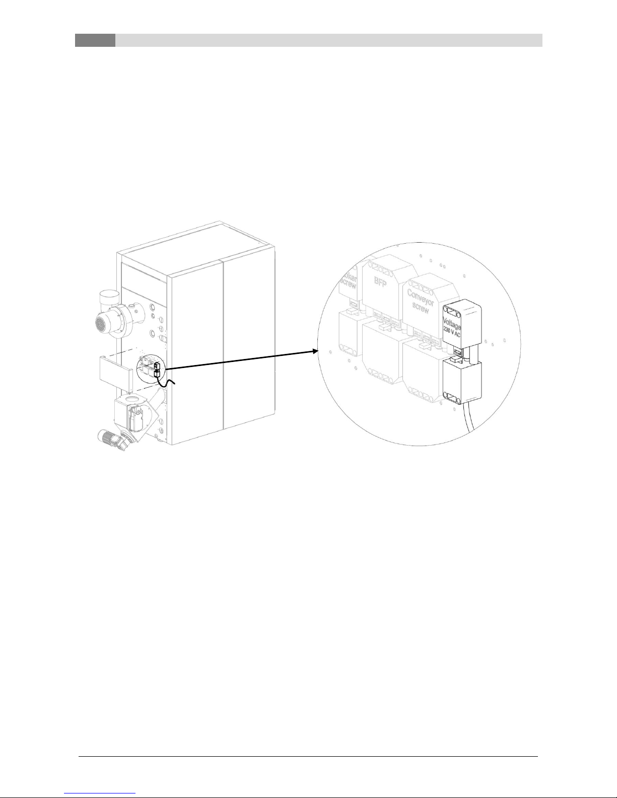
7.1 Starting the system
To switch on the display, the following condition must be met:
The boiler must be connected with the following plug to the power supply (see Figure 7.1)
If this condition is fulfilled, the starting process of the display, which takes 1-2 minutes, begins.
Figure 7.1: Plug on the boiler for the connection to the power supply
Description of the menu navigation system and settings
7
Betriebsanleitung_PS_10_60_Touch_Englisch_V1.3 17
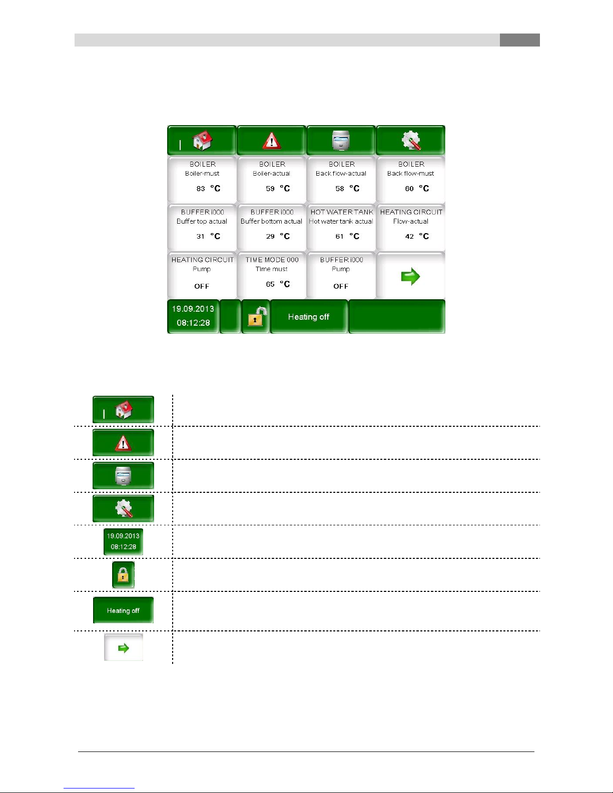
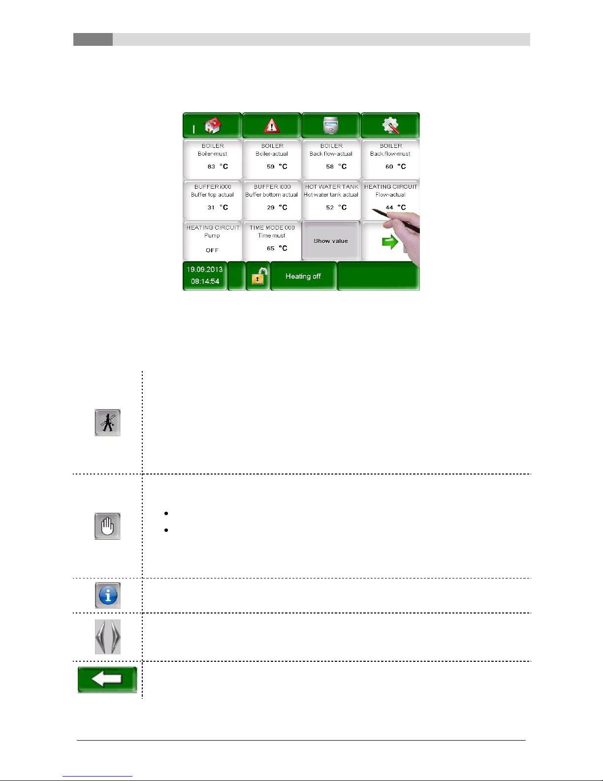
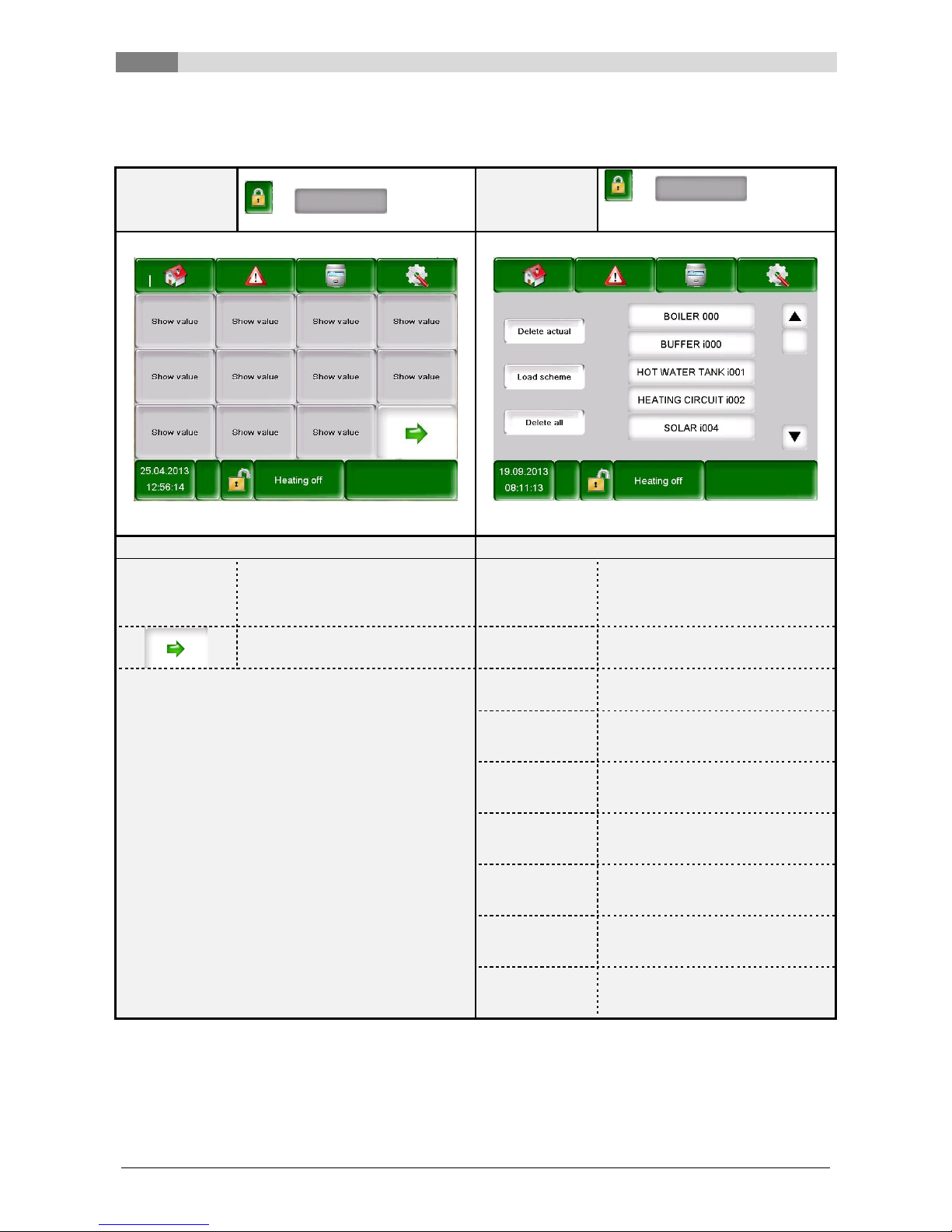
7.2 Main menu
After the starting process of the display, Figure 7.2 appears. In the middle of the screen important values for
boiler, buffer, hot water tank, heating circuit, and so on, are shown, which can be adapted individual (see
chapter 7.8).
Figure 7.2: Main menu
By touching the following button
the main menu will be displayed.
(see Figure 7.2)
fault messages (warnings & alarms) will be displayed.
(see Figure 7.16)
the individual modules (boiler, hot water tank, buffer, heating circuit, solar, Hydr.
compensator, net pump, zone valve, ext. demand) will be displayed.
(see Figure 7.17)
the menu settings (network configuration, E-Mail, screen saver) will be displayed.
(see Figure 7.96, visible only with code!)
you can set and modify date & time.
(see Figure 7.8, Modification only with code!)
you will be taken to the code entry screen.
(see Figure 7.4)
the heating system can be switched on/off. (see Figure 7.6 and Figure 7.7)
In general the field is used to display the operating conditions, which are shown in
chapter 5.
you will be taken to the second page of the value overview on the main menu.
7
Description of the menu navigation system and settings
18 Betriebsanleitung_PS_10_60_Touch_Englisch_V1.3
7.3 Operation and handling
The touch panel is a touch-sensitive screen and a display and control unit. By touching the screen you can
change released values or move to other pages. The touching can be done with finger, pen, pencil, etc.
Figure 7.3: Operation of the screen with fingers or pen
NOTE: The values shown in the individual screenshots are not default values!
7.4 Explanation of the symbols
In this section important symbols are explained, which are displayed on the following menu pictures.
The CHIMNEY SWEEPING FUNCTION is available as a test mode for the chimney
sweeper. The boiler is precisely operated using rated output and the chimney sweeper can
carry out its test measurements. This condition is exited with deactivation or exceeding of
the boiler maximum temperature or where the maximum chimney sweeping time is
exceeded. All loads are set to the permissible maximum value. Any measurements should
only be carried out if the “chimney sweeping mode” appears on the display and an
appropriate flame has been formed. Otherwise there is no guarantee that the boiler will
demonstrate optimum combustion. It is possible that the boiler will only work in ignition or
burning phase.
By the Aggregate-Test the connected components can be tested individually
The symbol is only visible, when
the code has been entered (see chapter 7.5, page 19) and
the boiler is in the operating condition “Heating off” (only applies to the Agg-test for
the boiler!)
When the Aggregate-Test is active, the symbol turns green and the message “AGG-Test
ACTIVE” is shown on the display area of the operating conditions.
Information’s such as firmware-module, hardware-module, software version etc., of each
module (boiler, hot water tank, buffer, solar, heating circuit) are shown here.
These symbols (navigation) can be used to navigate between the pages in each module
(boiler, hot water tank, buffer, solar, heating circuit, hydr. compensator, net pump, zone
valve, ext. demand). An alternative to the illustrated method of navigation is the wiping to the
right or left on the screen.
Pressing this button returns you to the overview of the modules (boiler, hot water tank,
buffer, solar, heating circuit, hydr. compensator, net pump, zone valve, ext. demand).
Description of the menu navigation system and settings
7
Betriebsanleitung_PS_10_60_Touch_Englisch_V1.3 19
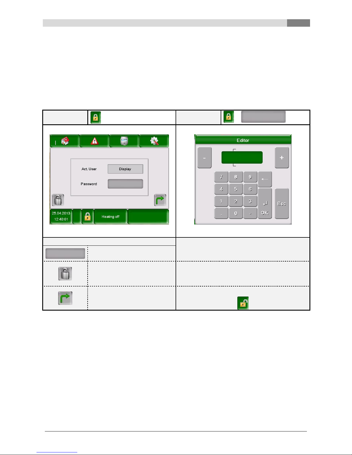
7.5 Code – entry
By entering the code, the following can be performed:
Changing values
Activate the Aggregate-Test (Explanation see chapter 7.4)
Setting or changing date & time (see chapter 7.7)
Navigation is in the menu settings possible (see chapter 7.11)
Navigation:
Navigation:
Screen:
Screen:
Figure 7.4: Code - entry
Figure 7.5: Editor for Code - entry
By touching the following button:
Note:
Figure 7.5 is displayed.
Enter the corresponding code (see below) and then
press „OK“ to confirm.
the main menu will be displayed
(if you have already entered a
code, this will lock the field that
has been changed)
The Code is:
111
the previous page will be
displayed
After that, the open padlock-icon appears:
7
Description of the menu navigation system and settings
20 Betriebsanleitung_PS_10_60_Touch_Englisch_V1.3
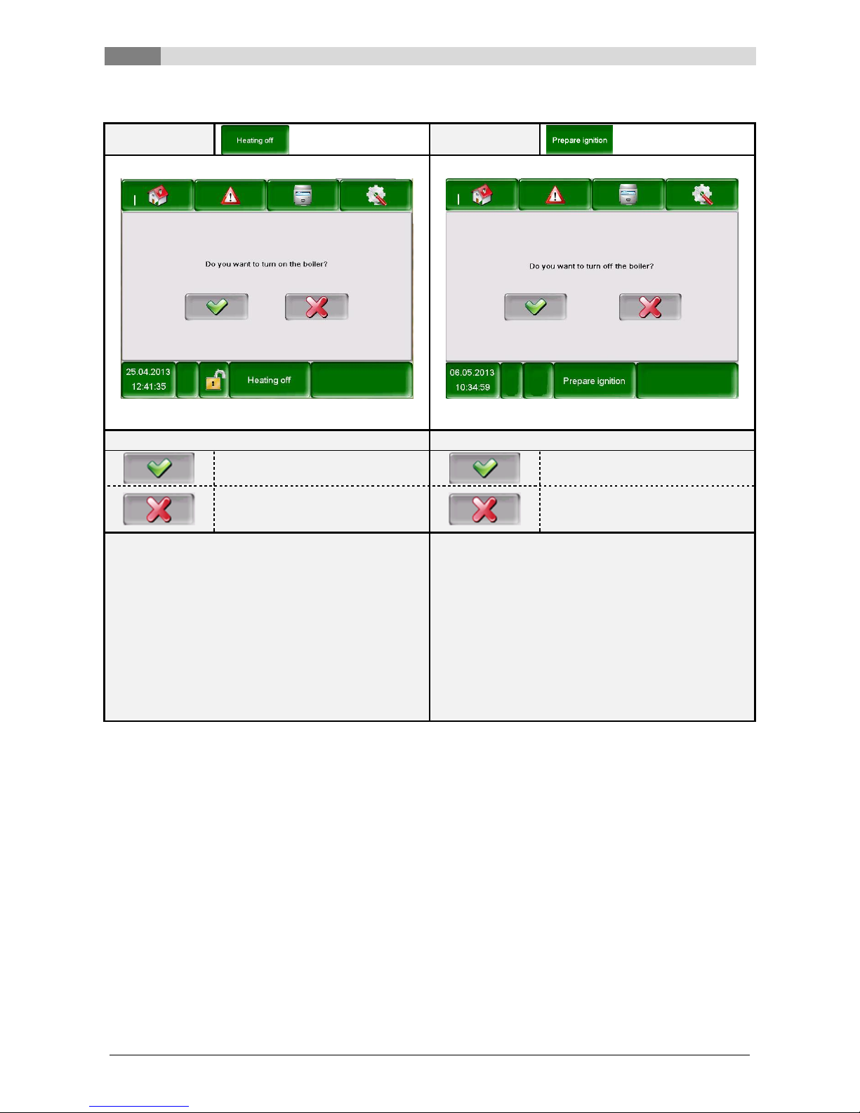
7.6 Switching the boiler on and off
Navigation:
Navigation:
Screen:
Screen:
Figure 7.6: Switching on the boiler
Figure 7.7: Switching off the boiler
By touching the following button:
By touching the following button:
the boiler will be switched on.
the boiler will be switched off.
the boiler will remain switched off
and the previous page will be
displayed.
the boiler will remain switched on
and the previous page will be
displayed.
Note:
Note:
The system can only be switched on if the code (see
chapter 7.5) has already been entered.
In all operating states (except cold start or Ready),
the system will then proceed to the burnout phase. If
the system is switched off during a cold start, the
cold start will finish and then the system will proceed
to the burnout phase. This will prevent an
unacceptably high amount of fuel building up in the
combustion chamber.
The system can only be switched on if the code (see
chapter 7.5) has already been entered.
Description of the menu navigation system and settings
7
Betriebsanleitung_PS_10_60_Touch_Englisch_V1.3 21
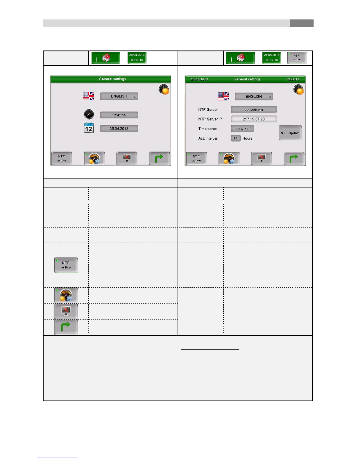
7.7 Selecting date and time
Navigation:
Navigation:
Screen:
Screen:
Figure 7.8: Selecting date and time
Figure 7.9: General settings for NTP
By touching the following button:
By touching the following button:
ENGLISH
you can select the language to be
used.
ENGLISH
you can select the language to be
used.
12:42:29
you can set the time.
pool.ntp.org
you can enter the name of the
server. (The server gets from the
network an IP-address and can so
communicate with the network.)
25.04.2013
you can set the date.
UTC+1
you can set the time zone.
you can activate NTP, which
means that the time and date will
be updated automatically.
(Is NTP active, time and date will
be updated automatically over the
network (=connection of the boiler
with the internet via LAN cable).
12
you can enter the update interval
in hours (Date and time can be
updated in the entered time
interval over the network, i. e. in
the case entered the time and
date will be updated every 12
hours.)
you can choose between summer
and winter time.
NTP Update
you can carry out an NTP update
(If you activate that update, time
and date will be updated
immediately and you don’t have to
wait for the act. interval).
you can lock the screen.
the main menu will be displayed.
Note:
NTP (Network Time Protocol) is used to synchronize
date and time automatically over the network.
A valid network connection via a LAN cable and the
connection with the internet is required.
In case of power failure:
Is NTP activated, the date and time will be
automatically updated after the switching on of the
system.
Is NTP not activated, the date and time will be
updated over an internal memory up to days
(manufacturer’s data). Is the boiler more than 10
days out of service, date and time must be set
manually.
7
Description of the menu navigation system and settings
22 Betriebsanleitung_PS_10_60_Touch_Englisch_V1.3
7.8 Determining values for the main menu
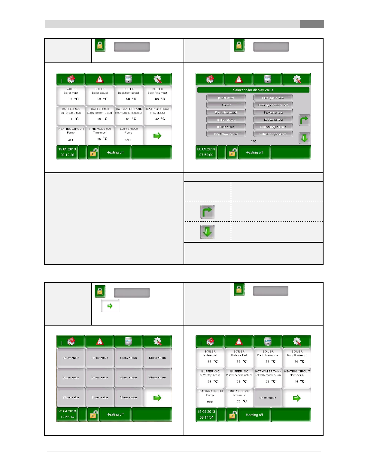
7.8.1 Adding display values to the main menu
Navigation:
111 OK
Navigation:
111 OK
Show value
Screen:
Screen:
Figure 7.10: Adding display values
Figure 7.11: Determining display values
By touching the following button:
By touching the following button:
Show value
an overview will be displayed in
which you can load values or add
individual values (see Figure
7.11).
Delete actual
you can delete the selected value
(see Figure 7.15)
the second page of the main
menu will be displayed.
Load scheme
you can load a default diagram
(see Figure 7.12)
Delete all
all the display values will be
deleted (see Figure 7.14)
BOILER 000
the boiler values which can be
selected manually will be
displayed (see Figure 7.13)
BUFFER i000
the buffer values which can be
selected manually will be
displayed
HOT WATER
TANK i001
the hot water tank values which
can be selected manually will be
displayed
HEATING
CIRCUIT i002
the heating circuit values which
can be selected manually will be
displayed
TIME MODE
000
the time mode values which can
be selected manually will be
displayed
SOLAR i004
the solar values which can be
selected manually will be
displayed
Description of the menu navigation system and settings
7
Betriebsanleitung_PS_10_60_Touch_Englisch_V1.3 23
Navigation:
111 OK
Show value Load scheme
Navigation:
111 OK
Show value BOILER 000
Screen:
Screen:
Figure 7.12: Load scheme
Figure 7.13: Determining display values
Note:
By touching the following button:
The values of the default scheme can also be
adapted individually. Thereby press 3-5 seconds on
the value and then follow the procedure described in
Figure 7.13.
Boiler-must,
Power, Back
flow-must, etc.
the value will be confirmed so that
it will be displayed on the main
menu.
the page for selecting the
individual modules will be
displayed again (see Figure 7.11)
the second page of display values
for the boiler or the individual
module will be displayed
Note:
The same applies to all other modules.
7.8.2 Deleting display values from the main menu
Navigation:
111
OK
Show value Delete
all
Navigation:
111
OK
Keep your finger on a random
display value for 3-5 seconds
Delete actual
Screen:
Screen:
Figure 7.14: Delete all display values
Figure 7.15: Delete actual display value
7
Description of the menu navigation system and settings
24 Betriebsanleitung_PS_10_60_Touch_Englisch_V1.3
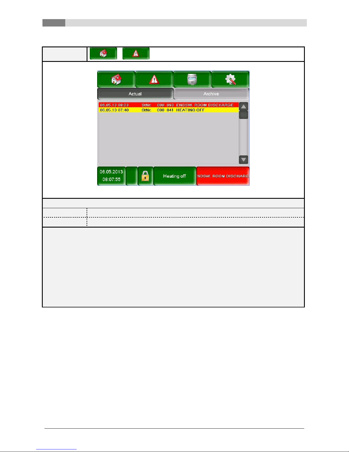
7.9 Fault messages and warnings
Navigation:
Screen:
Figure 7.16: Fault messages
By touching the following button:
Actual
current fault messages will be displayed.
Archive
all fault messages will be displayed.
Note:
A red highlighted field represents an active fault (These fault also appears in the lower right box of the
screen).
An orange highlighted field represents a warning.
A yellow highlighted field represents information’s (No fault has occurred).
A green highlighted field, where the fault text is crossed out, represents a fault or a warning which is
receipted and not active anymore (only in the area archive obvious)
An overview of all errors and their correction is shown in chapter 9 (starting on page 80).
Description of the menu navigation system and settings
7
Betriebsanleitung_PS_10_60_Touch_Englisch_V1.3 25
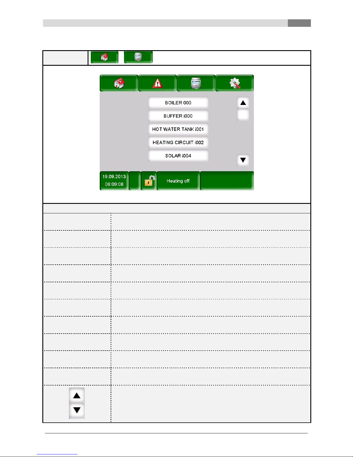
7.10 Modules
Navigation:
Screen:
Figure 7.17: Overview modules
By touching the following button:
BOILER 000
the „boiler values“ menu will be displayed
(see chapter 7.10.1 – page 26)
BUFFER i000
the „buffer values“ menu will be displayed
(see chapter 7.10.2 – page 29)
HOT WATER TANK i001
the „hot water tank values“ menu will be displayed
(see chapter 7.10.3 – page 31)
HEATING CIRCUIT i002
the „heating circuit values“ menu will be displayed
(see chapter 7.10.4 – page 34)
TIME MODE 000
the „time mode“ menu will be displayed
(see chapter 7.10.5 – page 37)
SOLAR i004
the „solar values“ menu will be displayed
(see chapter 7.10.6 – page 38)
HYDR. COMPENSATOR
i000
the „hydr. compensator “ menu will be displayed
(see chapter 7.10.7 – page 46)
NET PUMP i001
the „net pump“ menu will be displayed
(see chapter 7.10.8 – page 47)
ZONE VALVE e003
the „zone valve“ menu will be displayed
(see chapter 7.10.9 – page 48)
EXT. REQUIREMENT
e004
the „external requirement“ menu will be displayed
(see chapter 7.10.10 – page 49)
you can navigate through the menu of the modules (up resp. down)
7
Description of the menu navigation system and settings
26 Betriebsanleitung_PS_10_60_Touch_Englisch_V1.3
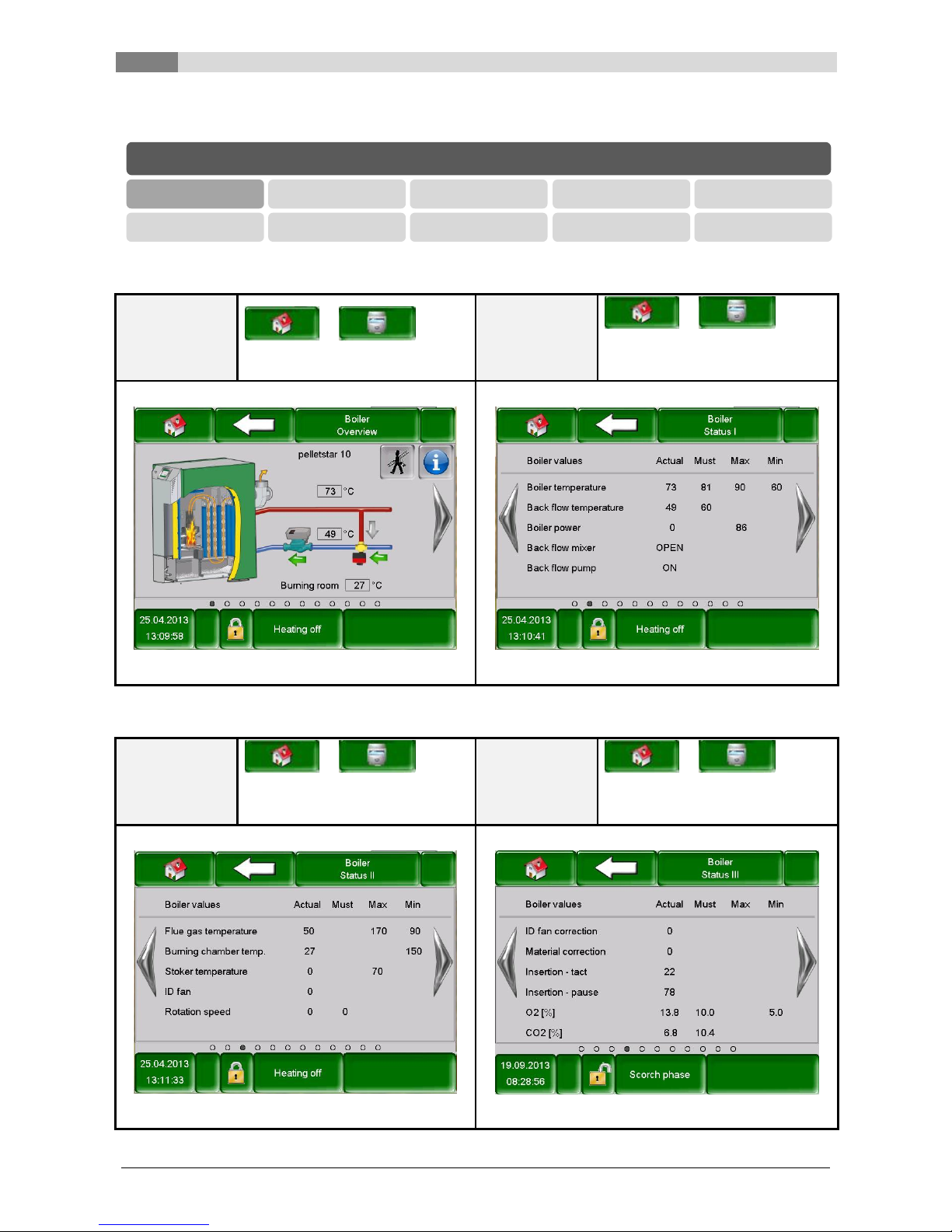
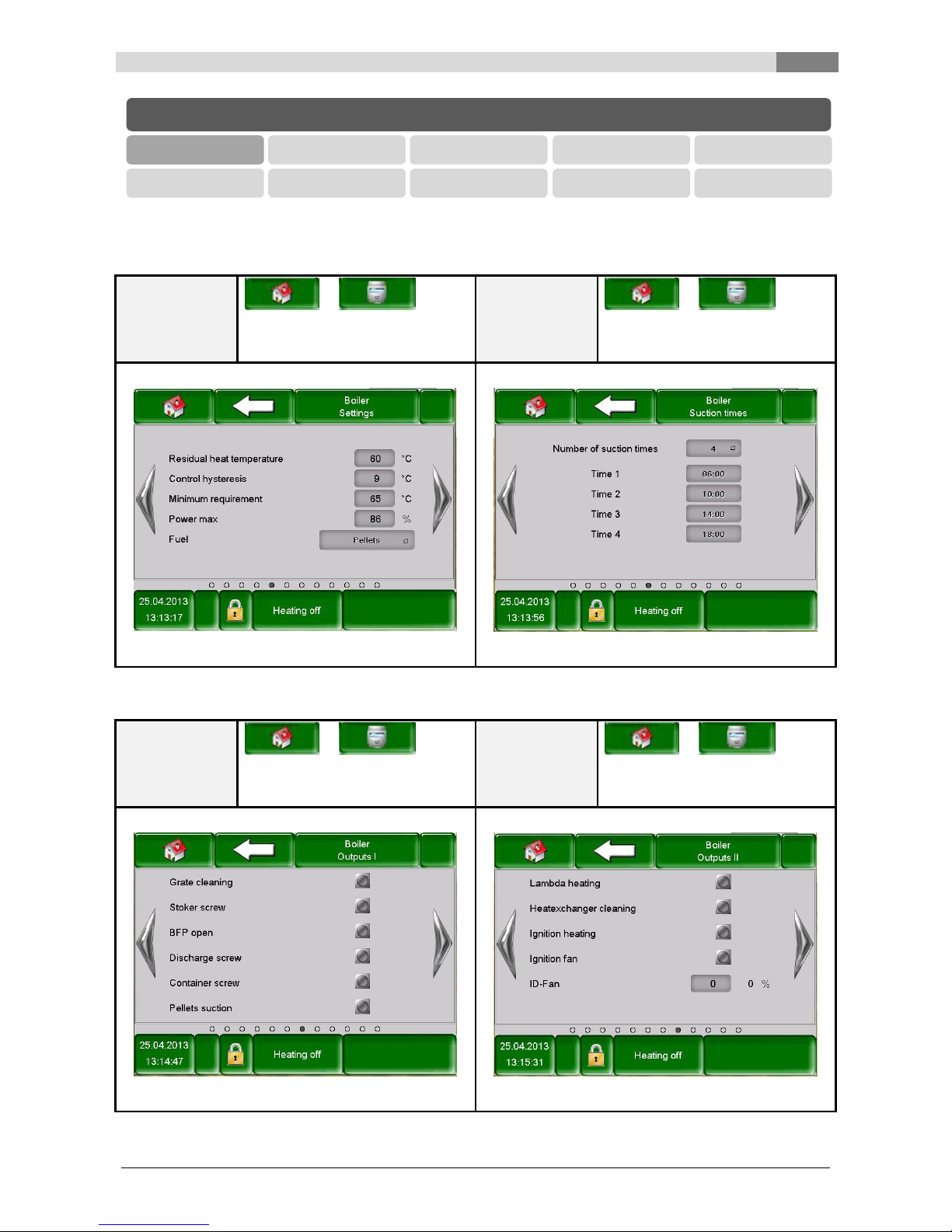
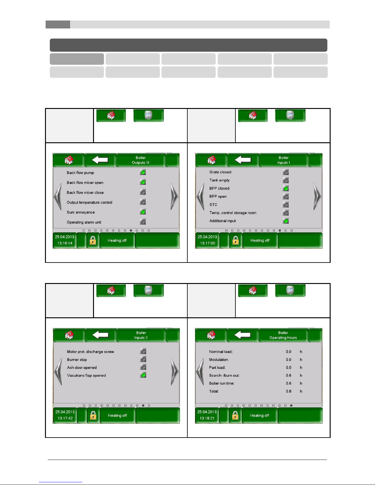
7.10.1 Boiler
NOTE: The terms on the respective figures are explained in chapter 8.1 – Terms and definitions (starting on
page 58).
Navigation:
BOILER 000
Navigation:
BOILER 000 navigate 1 page to the
right
Screen:
Screen:
Figure 7.18: Overview – Boiler
Figure 7.19: Status 1 – Boiler
Navigation:
BOILER 000 navigate 2 pages to
the right
Navigation:
BOILER 000 navigate 3 pages to
the right
Screen:
Screen:
Figure 7.20: Status 2 – Boiler
Figure 7.21: Status 3 – Boiler
MODULES
Boiler
Buffer
Hot water tank
Heating circuit
Time mode
Solar
Hydr. compensat.
Net pump
Zone valve
Ext. Requirement
Description of the menu navigation system and settings
7
Betriebsanleitung_PS_10_60_Touch_Englisch_V1.3 27
NOTE: The terms on the respective figures are explained in chapter 8.1 – Terms and definitions (starting on
page 58).
Navigation:
BOILER 000 navigate 4 pages to
the right
Navigation:
BOILER 000 navigate 5 pages to
the right
Screen:
Screen:
Figure 7.22: Settings – Boiler
Figure 7.23: Suction times – Boiler
Navigation:
BOILER 000 navigate 6 pages to
the right
Navigation:
BOILER 000 navigate 7 pages to
the right
Screen:
Screen:
Figure 7.24: Outputs 1 – Boiler
Figure 7.25: Outputs 2 – Boiler
MODULES
Boiler
Buffer
Hot water tank
Heating circuit
Time mode
Solar
Hydr. compensat.
Net pump
Zone valve
Ext. Requirement
7
Description of the menu navigation system and settings
28 Betriebsanleitung_PS_10_60_Touch_Englisch_V1.3
NOTE: The terms on the respective figures are explained in chapter 8.1 – Terms and definitions (starting on
page 58).
Navigation:
BOILER 000 navigate 8 pages to
the right
Navigation:
BOILER 000 navigate 9 pages to
the right
Screen:
Screen:
Figure 7.26: Outputs 3 – Boiler
Figure 7.27: Inputs 1 – Boiler
Navigation:
BOILER 000 navigate 10 pages to
the right
Navigation:
BOILER 000 navigate 11 pages to
the right
Screen:
Screen:
Figure 7.28: Inputs 2 – Boiler
Figure 7.29: Operating hours – Boiler
MODULES
Boiler
Buffer
Hot water tank
Heating circuit
Time mode
Solar
Hydr. compensat.
Net pump
Zone valve
Ext. Requirement
Description of the menu navigation system and settings
7
Betriebsanleitung_PS_10_60_Touch_Englisch_V1.3 29
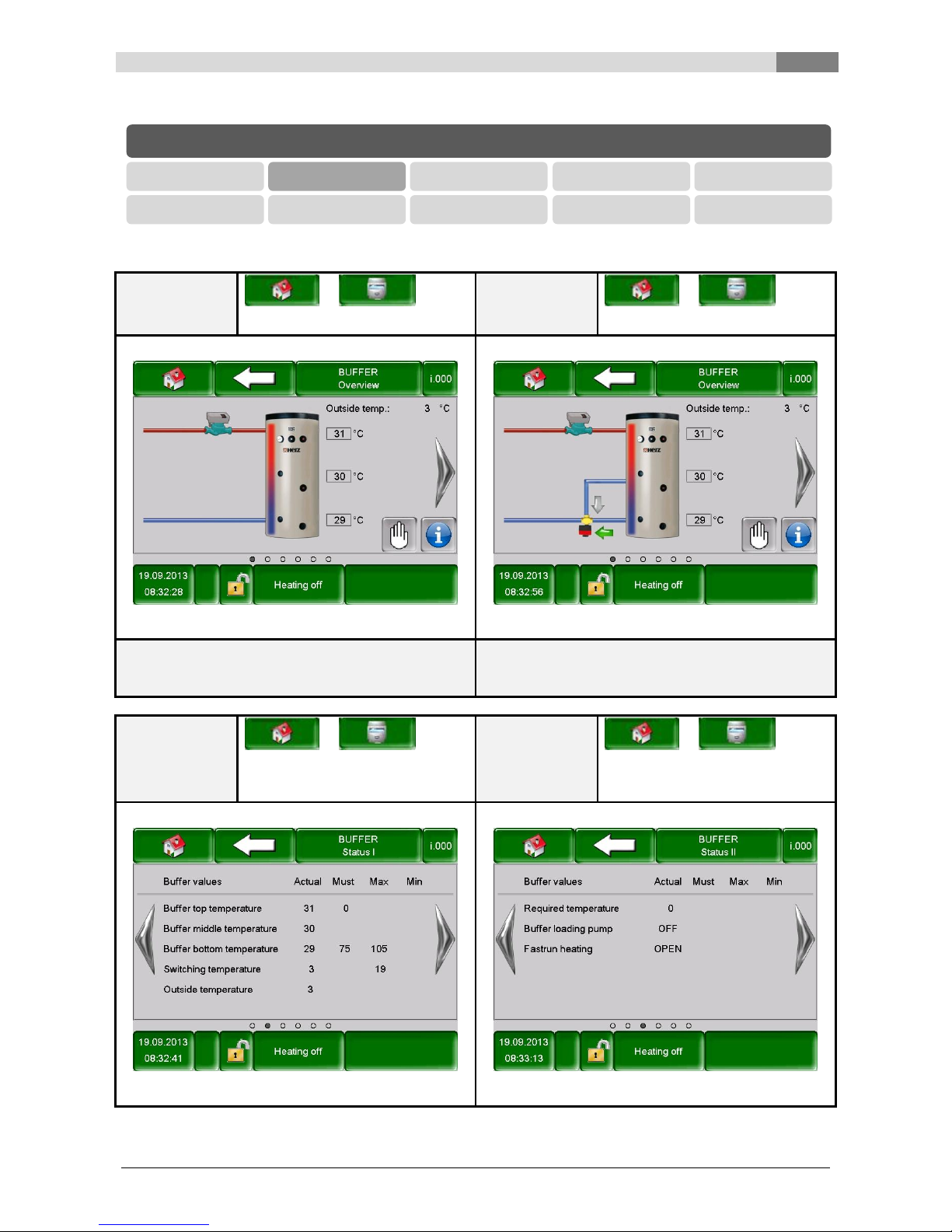
7.10.2 Buffer
NOTE: The terms on the respective figures are explained in chapter 0 – Terms and definitions (starting on
page 64).
Navigation:
BUFFER i000
Navigation:
BUFFER i000
Screen:
Screen:
Figure 7.30: Overview – Buffer
Figure 7.31: Overview by fastrun – Buffer
Note:
Figure 7.31 is displayed, when in Figure 7.35
“Fastrun“ is activated.
Navigation:
BUFFER i000 navigate 1 page to
the right
Navigation:
BUFFER i000 navigate 2 pages to
the right
Screen:
Screen:
Figure 7.32: Status 1 – Buffer
Figure 7.33: Status 2 – Buffer
MODULES
Boiler
Buffer
Hot water tank
Heating circuit
Time mode
Solar
Hydr. compensat.
Net pump
Zone valve
Ext. Requirement
 Loading...