

Hertz Ci3 C100.2FM-S3, Ci3 K130.2-S3, Ci3 K165.2FM-S3, Ci3 C165.2FM-S3, Ci3 C130.2-S3 User guide
...Page 1
ENGINEERED IN GERMANY
Page 2

Page 3

Congratulations!
Dear Customer,
Congratulations on your purchase of this high-quality product.
HELIX COMPOSE highlights best quality, excellent manufacturing and state-of-the-art sound quality.
Thanks to more than 30 years of experience in research and development of audio products HELIX COMPOSE sets
new standards in the car audio speaker market.
We wish you many hours of enjoyment with your new HELIX COMPOSE components.
Yours
AUDIOTEC FISCHER Team
General instructions
General instructions for installing HELIX
loudspeakers
To prevent damage to the speakers and possible injury, read this manual carefully and follow all installation
instructions. This product has been checked for proper
function prior to shipping and is guaranteed against manufacturing defects.
For a proper performance and to ensure full warranty
coverage, we strongly recommend to get this product installed by an authorized HELIX dealer.
If you choose to perform your own installation read the
following information and precautions carefully.
Failure to follow the stated precautions may result in
personal injury and / or damage to the audio system or
vehicle.
1. Always make sure that the speaker will t into the in-
tended mounting location and that there is adequate
depth for the magnet system.
2. Check for adequate space between speaker and
window, window crank, power window mechanism,
seat, rear deck torsion bars, and other items which
may interfere with the speaker`s mounting. This
is very important if any hole cutting is required.
Detailed size information is indicated in the dimension section of this manual. Take care that the mount-
ing surface is at and free from all obstructions.
3. Ensure that the loudspeakers are correctly connect-
ed in polarity. Exchanging plus and minus may result
in signicant loss of sound quality. The positive leads
of the loudspeakers are marked red.
4. Make sure that all speaker wiring is fully protected
from cutting or wear at sharp edges, which can lead
to short circuits that may damage your head unit,
amplier and / or speaker system.
5. Verify that all connection wires are long enough in
order to avoid any mechanical stress on the wires or
the connectors.
6. Make sure that all components are mounted prop-
erly.
7. Do not mount the components where water may
splash on them.
8. The quality of the installation has a signicant eect
on the overall performance of the speaker system.
Treat each installation step with a high degree of
attention.
9. Avoid low frequency cancellation caused by air leak-
age between the speaker basket and the mounting
surface (e.g. mounted on a bended or uneven surface or mounted in an oversized hole).
10. Mounting panel reinforcement may be necessary in
some cases in order to ensure a stable, torsion-free
and even surface. This can be achieved by mounting
the speaker on a metal, plastic or wooden sub-bae
behind the body or door panel. Consult an installation specialist for further advices.
11. In most cases you can use the original speaker
mounting locations in the doors, A-pillars, body panels or the rear deck. If these are not available you
have to prepare your own secure installation place.
Due to their structural integrity and accessibility the
precut mounting holes should be used whenever
possible. Information on a proper mounting can be
found in the section “Installation” of this manual.
IMPORTANT: Never cut any metal that is an integral part
of an automobile`s safety or structural car body.
We strongly recommend that you operate the complete
audio system at low volume before nal installation. So
you can check whether each speaker is working before
securing the loudspeakers into their mounting locations.
Find your composition
Go to www.audiotec-fischer.com/compose to
explore the whole HELIX COMPOSE platform
3
Page 4
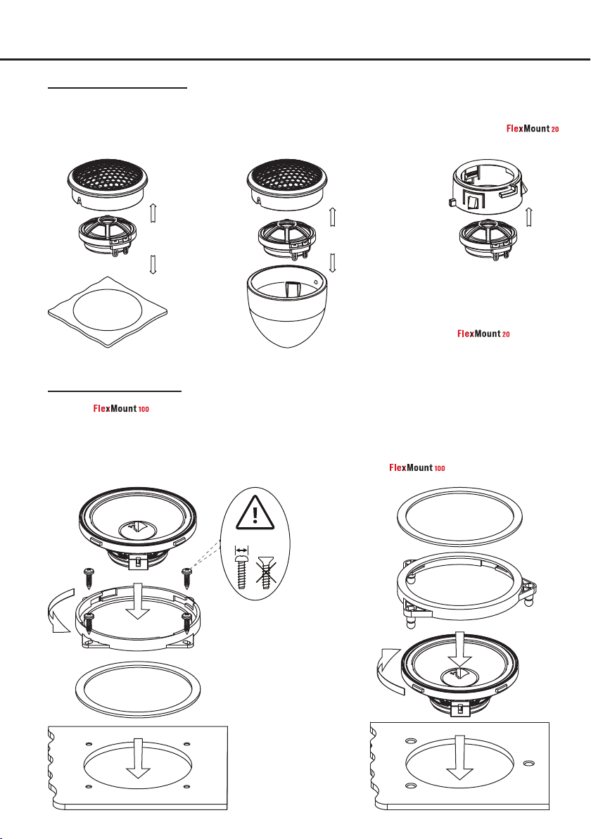
Installation
Mounting Ci3 T20FM-TI
Option a:
Flush mount
Option b:
Angle mount
Option c:
Professional integration with
optionally available
car- specic adaptor*
Step 1
Step 2
Step 1
Step 2
*Contact your retailer or visit
www.audiotec-scher.com/compose
for an up-to-date overview of
available car-specic
adaptors.
Mounting Ci3 M100FM
Note: the adaptor rings can be mounted in two directions. Make sure to use the appropriate mounting
option for your vehicle.
Option a:
Mounting with the enclosed universal
adaptor rings
Step 2
Step 1
max.
8 mm
Option b:
Professional integration with optionally available car-specic adaptor*
Step 1
Step 2
Step 3
Step 3
4
Page 5
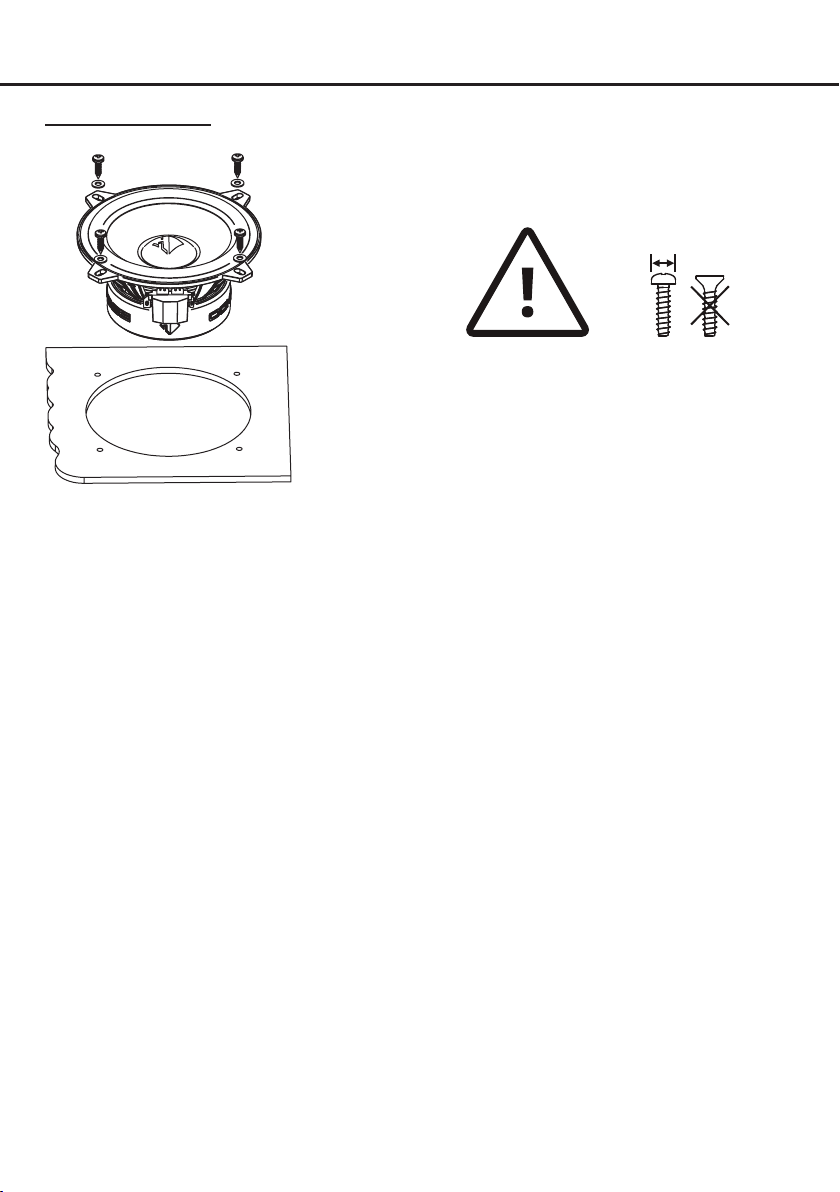
Mounting Ci3 W130
max.
8 mm
Attention: To avoid damage to the speak-
ers, do not use countersunk screws and
do not overtighten the screws!
5
Page 6
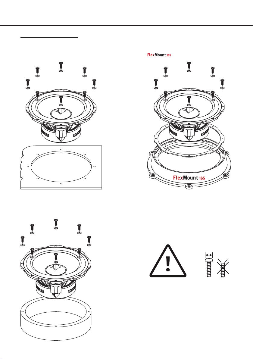
Installation
Mounting Ci3 W165FM
Option a:
Universal mounting
Option b:
Professional integration with optionally available
car-specic adaptor*
Option c:
Mounting with universal mounting adaptor
Attention: To avoid damage to the speakers, do not use countersunk screws and
do not overtighten the screws!
Universal speaker
adaptor
*Contact your retailer or visit www.audiotec-scher.com/compose for an up-to-date overview of available adaptors.
6
max.
8 mm
Page 7
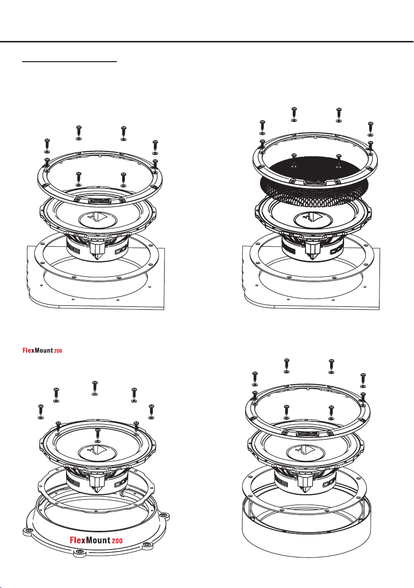
Mounting Ci3 W200FM
Option a:
Universal mounting without grille
Option b:
Universal mounting with grille
Option c:
Professional integration with optionally available
car-specic adaptor*
*Contact your retailer or visit www.audiotec-scher.com/compose for an up-to-date overview of available adaptors.
Option d:
Mounting with universal mounting adaptor
Universal speaker
adaptor
7
Page 8
Installation
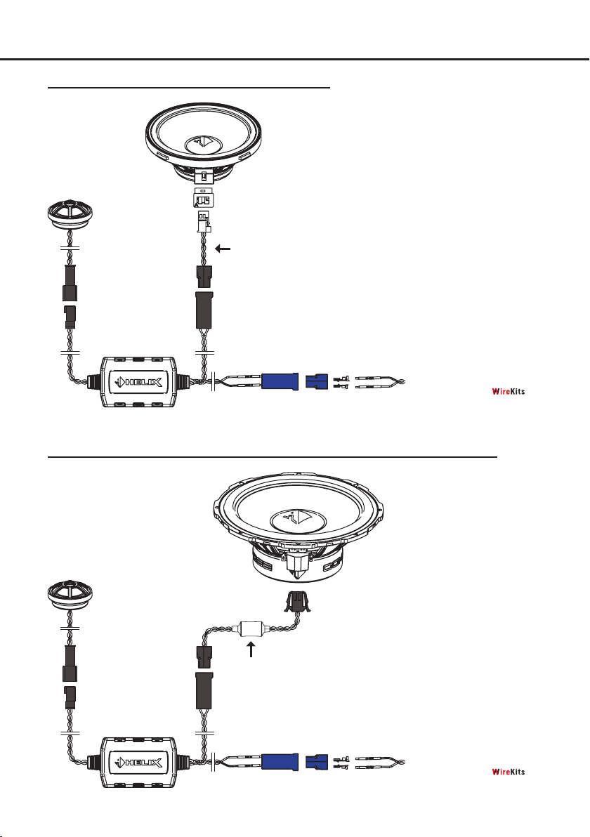
Wiring 2-way component system Ci3 K100.2FM
Connection cable
(included)
Connection to signal source
via the enclosed connectors or
optional COMPOSE
Wiring 2-way component system Ci3 K130.2 / Ci3 K165.2FM / Ci3 K200.2FM
Connection cable
(included)
Connection to signal source
via the enclosed connectors or
optional COMPOSE
Ensure that all components are correctly connected (phase), i.e. plus to plus and minus to minus.
8
Page 9
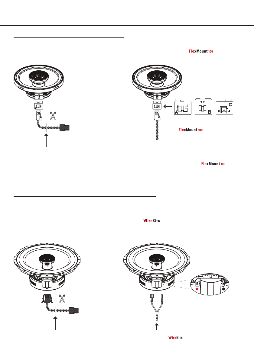
Wiring 2-way coaxial system Ci3 C100.2FM
Option a:
Universal connection
Option b: Direct connection to OEM connector with
Cut o the plug of the enclosed connection cable and
connect it to the signal source
From factory
Connection cable
(included)
cable harness
* Contact your retailer or visit www.audiotec-scher.com/compose
for an up-to-date overview of available car-
specic adaptors.
Wiring 2-way coaxial system Ci3 C130.2 / Ci3 C165.2FM
Option a: Universal connection with enclosed con-
nection cable
Option b: Universal connection to the blade terminals via
optional car-specic harness or COMPOSE
optionally available car-
specic adaptor
Car-specic FlexConnect adaptor –
comes with the optionally available
adaptor rings*
Cut o the plug of the enclosed connection cable and
connect it to the signal source.
Connection cable
(included)
+ (positive): large at terminal
- (negative): small at terminal
Optional car-specic wiring
harness or COMPOSE
Ensure that all components are correctly connected (phase), i.e. plus to plus and minus to minus.
9
Page 10
Installation
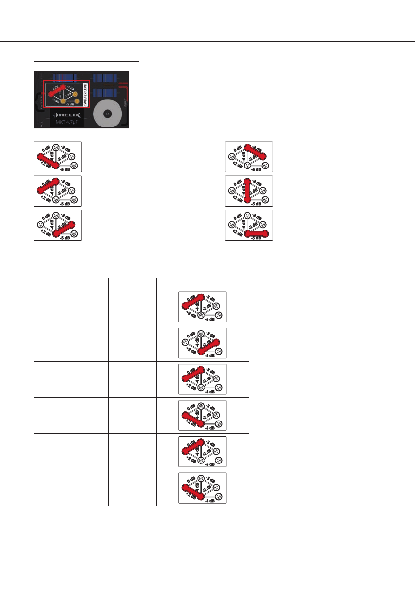
Tweeter level adjustment
The crossover allows to optimize the level of the connected tweeter internally by
repositioning the tweeter level jumper. Therefore open the crossover housing, pull
the jumper straight upwards and reinsert it to the desired position.
The correct tweeter level setting strongly depends on the location of the speakers.
Then conrm the level by listening to the speakers and modify the jumper setting if
needed.
+2 dB: The level of the tweeter is
increased by 2 dB.
0 dB: The tweeter has the optimum
level for most applications.
-2 dB: The level of the tweeter is
reduced by 2 dB.
We recommend to use the settings in the table below as starting point:
Speaker kit Level Jumper position
Ci3 K100.2FM-S3 0 dB
Ci3 K130.2-S3 -2 dB
Ci3 K165.2FM-S3 0 dB
Ci3 K165.2FM-S2 +2 dB
-3 dB: The level of the tweeter is
reduced by 3 dB.
-4 dB: The level of the tweeter is
reduced by 4 dB.
-5 dB: The level of the tweeter is
reduced by 5 dB.
Ci3 K200.2FM-S3 0 dB
Ci3 K200.2FM-S2 +2 dB
10
Page 11
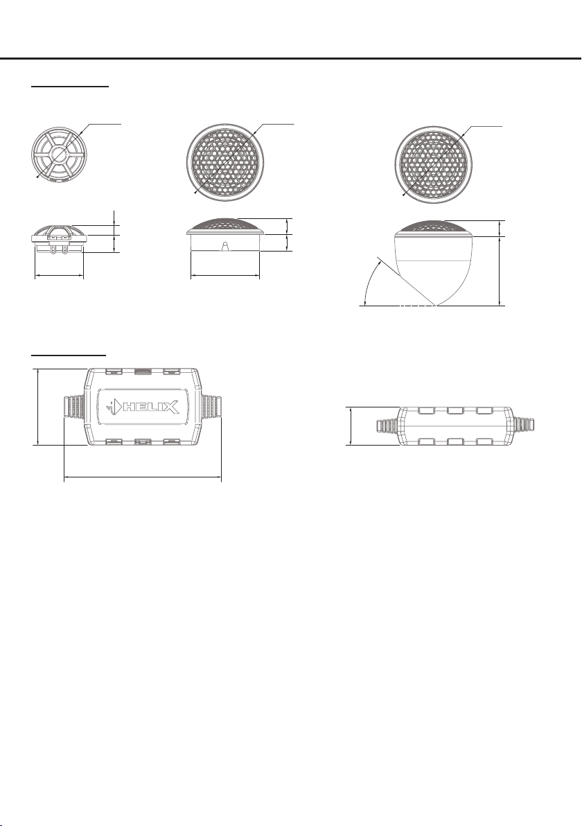
Dimensions
Ci3 T20FM-TI
Without housing
ø32.0mm
ø1.26”
ø28.0mm
ø1.10”
Ci3 FX-UNI.2
1.98”
50.4mm
5.6mm
0.22”
9.8mm
0.39”
With housing for ush mount
ø45.0mm
ø1.77”
9.3mm
9.5mm
40.0mm
1.58”
0.37”
0.37”
With housing for angle mount
40°
0.98”
25.0mm
ø45.0mm
ø1.77”
9.3mm
0.37”
40.1mm
1.58”
103.3mm
4.07”
11
Page 12
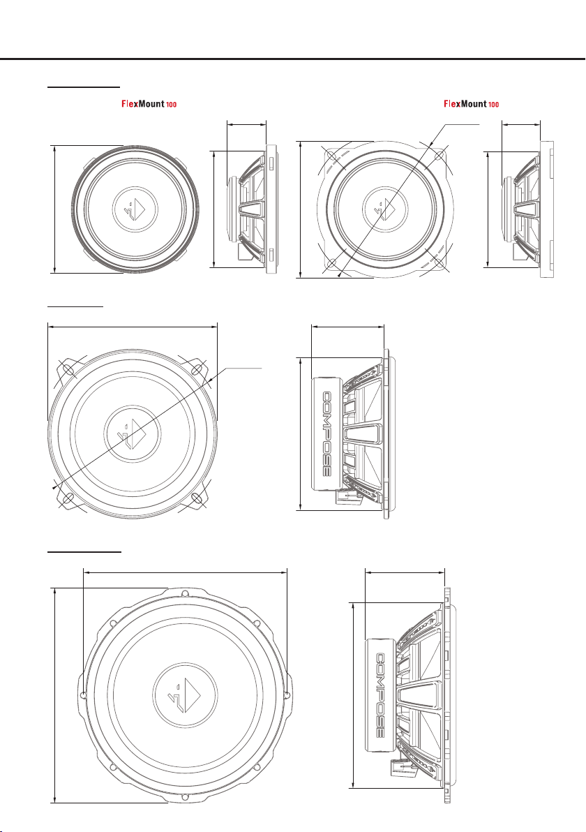
Dimensions
Ci3 M100FM
Speaker without
30.0mm
1.18”
Speaker with assembled universal
ø116.6mm
ø4.59”
29.5mm
1.16”
ø3.86”
ø98.0mm
Ci3 W130
Ci3 W165FM
ø130.0mm
ø5.12”
ø156.0mm
ø6.14”
ø3.50”
ø89.0mm
ø139.0mm
ø5.47”
4.11”
104.5mm
ø4.59”
ø116.5mm
55.4mm
2.18”
60.7mm
2.39”
ø3.50”
ø89.0mm
12
ø6.50”
ø165.0mm
ø5.59”
ø142.0mm
Page 13
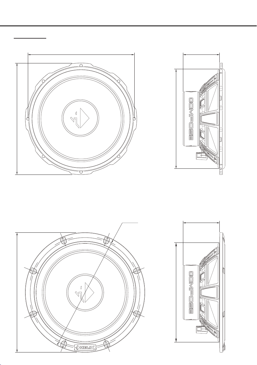
Ci3 W200FM
Speaker without adaptor ring
ø186.0mm
ø7.32”
63.7mm
2.51”
ø7.68”
ø195.0mm
Woofer with assembled universal mounting ring
ø8.22”
ø208.9mm
ø196.5mm
ø7.74”
ø6.83”
ø173.5mm
ø6.83”
ø173.5mm
63.7mm
2.51”
13
Page 14
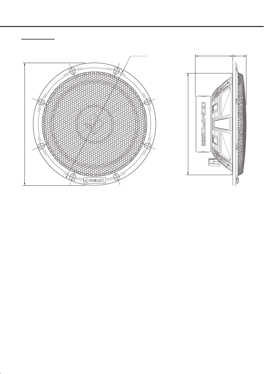
Dimensions
Ci3 W200FM
Woofer with assembled universal mounting ring and grille
ø196.5mm
ø7.74”
63.7mm
2.51”
23.0mm
0.91”
ø8.22”
ø208.9mm
ø6.83”
ø173.5mm
14
Page 15
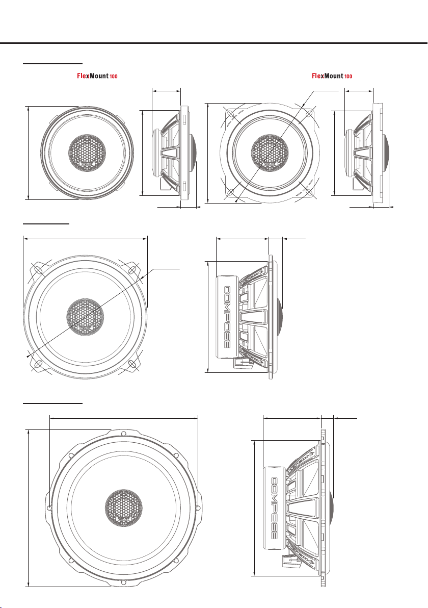
Ci3 C100.2FM
Speaker without
30.0mm
1.18”
Speaker with assembled universal
ø116.6mm
ø4.59”
29.5mm
1.16”
ø3.86”
ø98.0mm
Ci3 C130.2
ø130.0mm
Ci3 C165.2FM
ø5.12”
ø156.0mm
ø6.14”
ø3.50”
ø89.0mm
16.3mm
0.64”
ø139.0mm
ø5.47”
4.11”
104.5mm
ø4.59”
ø116.5mm
55.4mm
2.18”
14.4mm
0.57”
60.7mm
2.39”
ø3.50”
ø89.0mm
13.1mm
0.52”
16.8mm
0.66”
ø6.50”
ø165.0mm
ø5.59”
ø142.0mm
15
Page 16
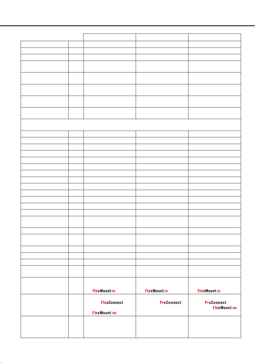
Technical data
Speaker kits Ci3 K100.2FM-S3 Ci3 K130.2-S3 Ci3 K165.2FM-S3
Power RMS / Max. P 80 / 120 Watts 90 / 135 Watts 100 / 150 Watts
Frequency response 120 Hz - 25,000 Hz 80 Hz - 25,000 Hz 60 Hz - 25,000 Hz
Impedance Z 3 Ω 3 Ω 3 Ω
Sensitivity SPL
Outer diameter
(
more data page 11 et sqq.)
Installation diameter
(more data page 11 et sqq.)
Installation depth
(more data page 11 et sqq.)
Dimensions crossover
Woofer
Impedance Z 3 Ω 3 Ω 3 Ω
DC resistance Re 3.0 Ω 3.1 Ω 3.0 Ω
Resonance frequency Fs 146 Hz 89 Hz 70 Hz
Mechanical Q factor Qms
Electrical Q factor Qes
Total Q factor Qts
Compliance Cms
Equivalent air volume Vas
Force factor B*l
Cone area Sd
Moving mass Mms 4.3 g 9.1 g 11.3 g
Mechanical resistance Rms
Voice coil diameter Ø
Voice coil winding
height
Max. linear excursion Xmax
91 dB @ 2.83V / 1m
87 dB @ 1W / 1m
Ø Tweeter: 32.0 mm / 1.26”
Woofer: 98.0 mm / 3.86”
Ø Tweeter: 32.0 mm / 1.26”
Woofer: 89.0 mm / 3.50”
Tweeter: 9.8 mm / 0.39”
Woofer: 30.0 mm / 1.18”
103.3 x 50.4 x 25.0 mm /
4.07 x 1.98 x 0.98”
4.49 3.11 4.17
1.02 0.97 1.05
0.83 0.74 0.84
280 μm/N 350 μm/N 454 μm/N
1.1 L 4.6 L 11.2 L
3.4 Tm 4.0 Tm 4.0 Tm
53 cm2
0.87 kg/s 1.65 kg/s 1.18 kg/s
25 mm 25 mm 25 mm
4.8 mm 10.5 mm 10.5 mm
+/- 2.0 mm +/- 3.2 mm +/- 3.2 mm
91 dB @ 2.83V / 1m
87 dB @ 1W / 1m
Tweeter: 32.0 mm / 1.26”
Woofer: 130.0 mm / 5.12”
Tweeter: 32.0 mm / 1.26”
Woofer: 116.5 mm / 4.59”
Tweeter: 9.8 mm / 0.39”
Woofer: 55.4 mm / 2.18”
103.3 x 50.4 x 25.0 mm /
4.07 x 1.98 x 0.98”
98 cm2
92 dB @ 2.83V / 1m
88 dB @ 1W / 1m
Tweeter: 32.0 mm / 1.26”
Woofer: 165.0 mm / 6.50”
Tweeter: 32.0 mm / 1.26”
Woofer: 142.0 mm / 5.59”
Tweeter: 9.8 mm / 0.39”
Woofer: 60.7 mm / 2.39”
103.3 x 50.4 x 25.0 mm /
4.07 x 1.98 x 0.98”
133 cm2
Tweeter
Impedance Z 4 Ω 4 Ω 4 Ω
Resonance frequency Fs 1800 Hz 1800 Hz 1800 Hz
Voice coil diameter Ø
Features
Tweeter
Woofer Paper with Cenosphere
Crossover Tweeter: 12 dB highpass,
20 mm 20 mm 20 mm
Ultra compact, titanium
dome, neodymium magnet
and
coating
, terminal, neodymium magnet
and
protection and
level adjustment
Ultra compact, titanium
dome, neodymium magnet
and
Paper with Cenosphere
coating
and
terminal
Tweeter: 12 dB highpass,
protection and
level adjustment
Woofer: 6 dB lowpass
16
Ultra compact, titanium
dome, neodymium magnet
and
Paper with Cenosphere
coating
,
terminal and
Tweeter: 12 dB highpass,
protection and
level adjustment
Woofer: 6 dB lowpass
Page 17
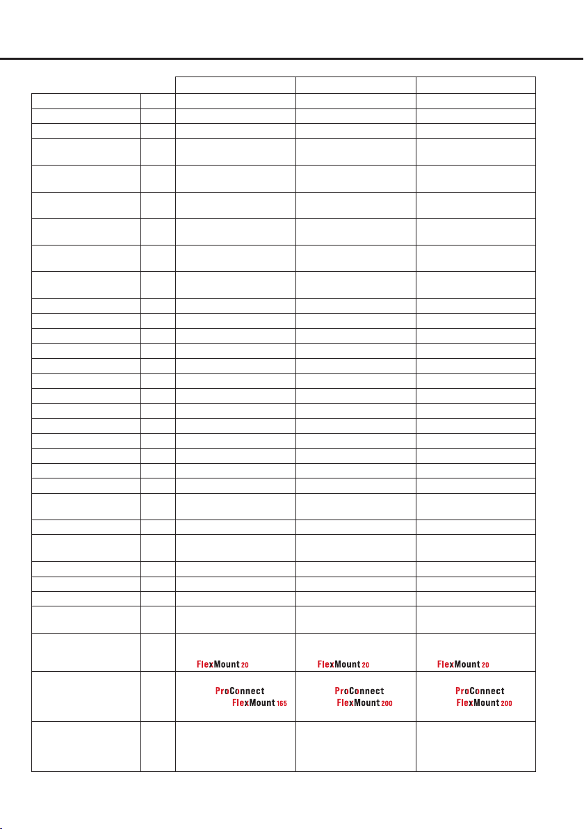
Speaker kits Ci3 K165.2FM-S2 Ci3 K200.2FM-S3 Ci3 K200FM.2-S2
Power RMS / Max. P 100 / 150 Watts 100 / 150 Watts 100 / 150 Watts
Frequency response 60 Hz - 25,000 Hz 50 Hz - 25,000 Hz 50 Hz - 25,000 Hz
Impedance Z 2 Ω 3 Ω 2 Ω
Sensitivity SPL
94 dB @ 2.83V / 1m
88 dB @ 1W / 1m
Outer diameter
(
more data page 11 et sqq.)
Installation diameter
(
more data page 11 et sqq.)
Installation depth
(
more data page 11 et sqq.)
Dimensions crossover
Ø Tweeter: 32.0 mm / 1.26”
Woofer: 165.0 mm / 6.50”
Ø Tweeter: 32.0 mm / 1.26”
Woofer: 142.0 mm / 5.59”
Tweeter: 9.8 mm / 0.39”
Woofer: 60.7 mm / 2.39”
103.3 x 50.4 x 25.0 mm /
4.07 x 1.98 x 0.98”
Woofer
Impedance Z 2 Ω 3 Ω 2 Ω
DC resistance Re 1.8 Ω 3.0 Ω 1.8 Ω
Resonance frequency Fs 74 Hz 67 Hz 72 Hz
Mechanical Q factor Qms
Electrical Q factor Qes
Total Q factor Qts
Compliance Cms
Equivalent air volume Vas
Force factor B*l
Cone area Sd
3.92 4.25 4.56
0.92 0.93 1.09
0.74 0.76 0.88
370 μm/N 300 μm/N 230 μm/N
8.8 L 19.0 L 14.5 L
3.4 Tm 5.1 Tm 4.0 Tm
133 cm2
Moving mass Mms 12.5 g 18.8 g 20.8 g
Mechanical resistance Rms
Voice coil diameter Ø
Voice coil winding
1.48 kg/s 1.87 kg/s 2.07 kg/s
25 mm 25 mm 25 mm
11.3 mm 11.6 mm 11.9 mm
height
Max. linear excursion Xmax
+/- 3.7 mm +/- 3.8 mm +/- 4.0 mm
94 dB @ 2.83V / 1m
90 dB @ 1W / 1m
Tweeter: 32.0 mm / 1.26”
Woofer: 195.0 mm / 7.68”
Tweeter: 32.0 mm / 1.26”
Woofer: 173.5 mm / 6.83”
Tweeter: 9.8 mm / 0.39”
Woofer: 63.7 mm / 2.51”
103.3 x 50.4 x 25.0 mm /
4.07 x 1.98 x 0.98”
214 cm2
96 dB @ 2.83V / 1m
90 dB @ 1W / 1m
Tweeter: 32.0 mm / 1.26”
Woofer: 195.0 mm / 7.68”
Tweeter: 32.0 mm / 1.26”
Woofer: 173.5 mm / 6.83”
Tweeter: 9.8 mm / 0.39”
Woofer: 63.7 mm / 2.51”
103.3 x 50.4 x 25.0 mm /
4.07 x 1.98 x 0.98”
214 cm2
Tweeter
Impedance Z 4 Ω 4 Ω 4 Ω
Resonance frequency Fs 1800 Hz 1800 Hz 1800 Hz
Voice coil diameter Ø
20 mm 20 mm 20 mm
Features
Tweeter
Ultra compact, titanium
dome, neodymium magnet
and
Woofer Paper with Cenosphere
coating
,
terminal and
Crossover Tweeter: 12 dB highpass,
protection and
level adjustment
Ultra compact, titanium
dome, neodymium magnet
and
Paper with Cenosphere
coating
,
terminal, and
grille
Tweeter: 12 dB highpass,
protection and
level adjustment
Ultra compact, titanium
dome, neodymium magnet
and
Paper with Cenosphere
coating
terminal, and
grille
Tweeter: 12 dB highpass,
Woofer: 6 dB lowpass
,
protection and
level adjustment
17
Page 18
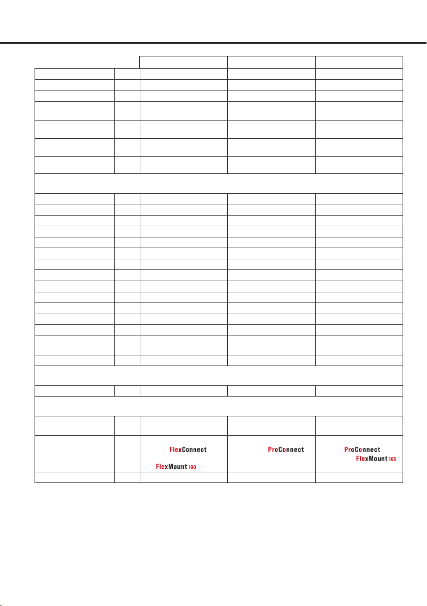
Technical data
Coaxial systems Ci3 C100.2FM-S3 Ci3 C130.2-S3 Ci3 C165.2FM-S3
Power RMS / Max. P 80 / 120 Watts 90 / 135 Watts 100 / 150 Watts
Frequency response 100 Hz - 25,000 Hz 80 Hz - 25,000 Hz 60 Hz - 25,000 Hz
Impedance Z 3 Ω 3 Ω 3 Ω
Sensitivity SPL
Outer diameter
(more data page 15 et sqq.)
Installation diameter
(more data page 15 et sqq.)
Installation depth
(more data page 15 et sqq.)
Woofer
Impedance Z 3 Ω 3 Ω 3 Ω
DC resistance Re 3.0 Ω 3.0 Ω 3.1 Ω
Resonance frequency Fs 137 Hz 92 Hz 72 Hz
Mechanical Q factor Qms
Electrical Q factor Qes
Total Q factor Qts
Compliance Cms
Equivalent air volume Vas
Force factor B*l
Cone area Sd
Moving mass Mms 3.0 g 7.6 g 10.4 g
Mechanical resistance Rms
Voice coil diameter Ø
Voice coil winding
height
Max. linear excursion Xmax
91 dB @ 2.83V / 1m
87 dB @ 1W / 1m
Ø 98.0 mm / 3.86” 130.0 mm / 5.12” 165.0 mm / 6.50”
Ø 89.0 mm / 3.50” 116.5 mm / 4.59” 142.0 mm / 5.59”
30.0 mm / 1.18” 55.4 mm / 2.18” 60.7 mm / 2.39”
4.37 2.76 4.02
0.78 0.90 1.04
0.66 0.68 0.82
456 μm/N 374 μm/N 466 μm/N
2.1 L 4.9 L 11.5 L
3.2 Tm 3.8 Tm 3.8 Tm
57 cm2
0.58 kg/s 1.60 kg/s 1.17 kg/s
25 mm 25 mm 25 mm
4.8 mm 10.5 mm 10.5 mm
+/- 2.0 mm +/- 3.2 mm +/- 3.2 mm
92 dB @ 2.83V / 1m
88 dB @ 1W / 1m
97 cm2
92 dB @ 2.83V / 1m
88 dB @ 1W / 1m
133 cm2
Tweeter
Voice coil diameter Ø
Features
Tweeter
Woofer Paper with Cenosphere
Crossover Integrated, 6 dB highpass Integrated, 6 dB highpass Integrated, 6 dB highpass
20 mm 20 mm 20 mm
Titanium dome and
neodymium magnet
coating
, terminal, neodymium magnet
and
Titanium dome and
neodymium magnet
Paper with Cenosphere
coating
and
terminal
Titanium dome and
neodymium magnet
Paper with Cenosphere
coating
terminal and
,
18
Page 19
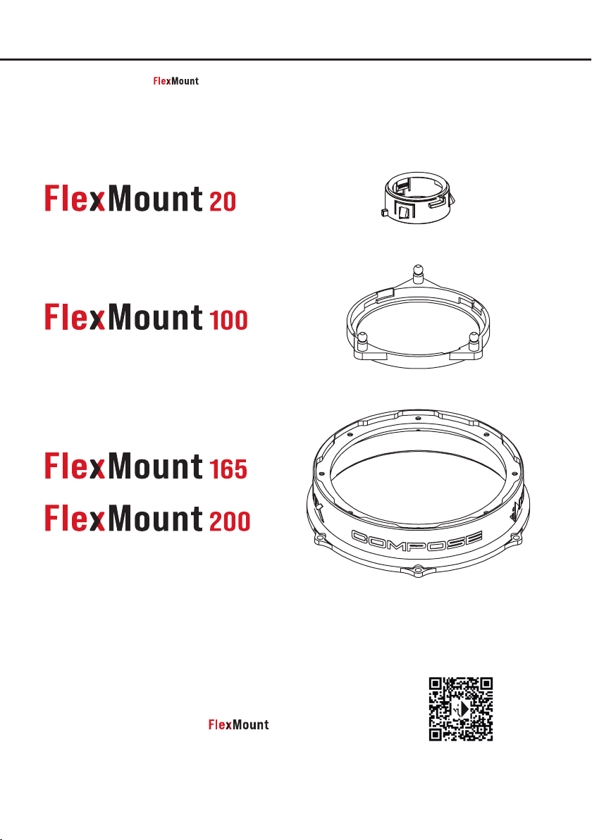
FlexMount car-specic adaptors
The optionally available car-specic adaptor rings allow a tailored and acoustically optimized
adaption of the HELIX COMPOSE speakers Ci3 T20FM-TI, Ci3 M100FM, Ci3 W165FM, Ci3 W200FM,
Ci3 C100.2FM-S3 and Ci3 C165.2FM-S3 to the vehicles original mounting location. Contact your retailer or visit
www.audiotec-scher.com/compose for an up-to-date overview of available adaptors.
Contact your retailer or visit
www.audiotec-scher.com/compose for an up-to-date
overview of available car-specic adaptors
19
Page 20

Correct disposal of this product
(Applicable in the European Union and other countries with separate collection systems)
If you want to dispose this product, do not mix it with general household waste. There is a separate collection system for used electronic products in accordance with
legislation that requires proper treatment, recovery and recycling. Contact your local government oce for details in locating a recycle facility close to you. Proper
recycling and waste disposal will help conserve resources and prevent detrimental eects on our health and the environment.
Warranty Disclaimer
The warranty service is based on the statutory regulations. Defects and damage caused by overload or improper handling are excluded from the warranty service. Any return can only take place following prior consultation, in the original packag-
ing together with a detailed description of the error and a valid proof of purchase. Technical modications, misprints and errors excepted!
For damages on the vehicle and the device, caused by handling errors of the device, we can’t assume liability. All HELIX speakers are tagged with a CE-Certication
mark. Thereby these devices are certied for the use in vehicles within the European Community (EC).
AUDIOTEC FISCHER GmbH
Hünegräben 26
57392 Schmallenberg
Germany
Made in China
 Loading...