

Page 1
hertzaudiovideo.com
HMD8 DSP
USER’S
MANUAL
rev. 1.3
Page 2

USER’S MANUAL
HMD8 DSP/
Index
1. PRODUCT DESCRIPTION / PRECAUTIONS ........................................................................................................................... 3
2. PACKAGE CONTENTS ............................................................................................................................................................. 4
3. HMD8 DSP INSTALLATION .................................................................................................................................................... 5
3.1 DEVICE INSTALLATION .................................................................................................................................................... 5
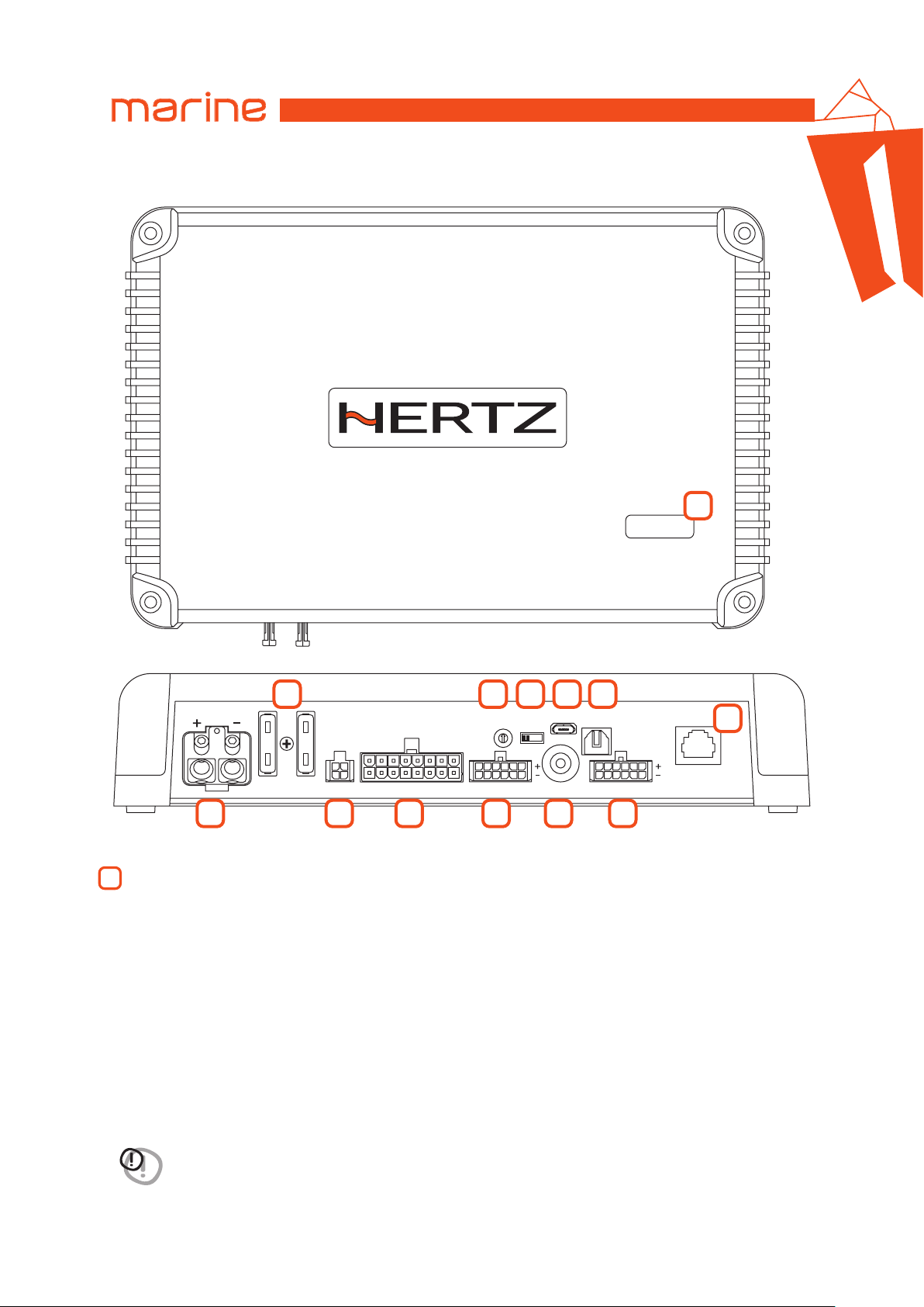
4. CONNECTION PANEL DESCRIPTION ..................................................................................................................................... 6
1 POWER .............................................................................................................................................................................. 6
2 FUSE ................................................................................................................................................................................ 7
3 CTRL (REM IN-OUT. / CONTROL) .................................................................................................................................... 7
4 SPEAKER OUT. .................................................................................................................................................................. 8
5 SPEAKER IN ...................................................................................................................................................................... 8
6 PRE IN ............................................................................................................................................................................... 8
7 SUB OUT ............................................................................................................................................................................ 9
8 OPTICAL IN ........................................................................................................................................................................ 9
9 PRESET. ............................................................................................................................................................................. 9
10 UPGRADE switch. ............................................................................................................................................................. 9
11 MIRCO USB. ...................................................................................................................................................................... 9
12 DRC ................................................................................................................................................................................ 9
13 LOGO STATUS ................................................................................................................................................................... 9
5. CONNECTIONS ...................................................................................................................................................................... 10
5.1 POWER SUPPLY AND REMOTE TURN ON. .................................................................................................................. 10
5.2 MEMORY SELECTION SWITCH ...................................................................................................................................... 11
5.3 INPUT SIGNALS ............................................................................................................................................................... 11
5.4 DIGITAL OPTICAL IN INPUT SIGNALS ............................................................................................................................ 12
5.5 OUTPUT SIGNALS ........................................................................................................................................................... 13
5.6 PC CONNECTION. ............................................................................................................................................................ 14
6. CONFIGURATION SOFTWARE ............................................................................................................................................. 15
6.1 LINK TO DEVICE .............................................................................................................................................................. 15
6.2 SAVE AND LOAD THE CONFIGURATION ...................................................................................................................... 16
6.3 SETTINGS ......................................................................................................................................................................... 16
6.4 AUDIO SETUP .................................................................................................................................................................. 17
6.4.1 GENERAL GUIDELINES. ...................................................................................................................................... 17
6.4.2 SOURCES ............................................................................................................................................................. 19
6.4.3 INPUT CHANNELS .............................................................................................................................................. 20
6.4.4 OUTPUT CHANNELS ........................................................................................................................................... 22
6.4.5 OUTPUT CHANNEL GROUPS ............................................................................................................................. 23
6.4.6 LISTENING ZONES .............................................................................................................................................. 24
6.4.7 MIXER .................................................................................................................................................................. 25
6.4.8 DELAYS AND DISTANCES ................................................................................................................................... 26
6.4.9 CROSSOVER ........................................................................................................................................................ 30
6.4.10 EQUALIZER .......................................................................................................................................................... 32
6.4.11 MEMORIES .......................................................................................................................................................... 33
6.4.12 GRAPH ................................................................................................................................................................. 39
6.4.13 WORK NOTES ...................................................................................................................................................... 41
6.5 EXTENDED FUNCTIONALITIES ...................................................................................................................................... 42
6.5.1 WIZARD ............................................................................................................................................................... 42
6.5.2 FEATURES. .......................................................................................................................................................... 43
6.5.3 REAL TIME ANALYSIS. ........................................................................................................................................ 43
6.5.4 STATUS BAR ........................................................................................................................................................ 44
7. TROUBLESHOOTING ............................................................................................................................................................. 45
7.1 SYNCHRONIZATION WITH A PC .................................................................................................................................... 45
7.2 FIRMWARE UPDATE ...................................................................................................................................................... 45
8. TECHNICAL SPECIFICATIONS .............................................................................................................................................. 46
2
Page 3
USER’S MANUAL
HMD8 DSP/
1
1. PRODUCT DESCRIPTION / PRECAUTIONS
Thank you for purchasing the HMD8 DSP amplifier for your marine sound system. Your amplifier has been designed and
manufactured to exacting standards in order to ensure years of musical enjoyment in your vessel. For maximum performance,
we highly recommend that you have your new amplifier installed by an authorized Hertz dealer. Your authorized dealer has the
training, expertise and installation equipment to ensure optimum performance from this product. Should you decide to install the
amplifier yourself, please take the time to read this manual thoroughly so as to familiarize yourself with its installation
requirements and setup procedures. If you have any questions regarding the instructions in this manual or any aspect of your
amplifier’s operation, please contact your authorized Hertz dealer for assistance.
This section describes the main features of the amplifier and the connector panel. Some operating procedures for the correct
installation and the best use of the product are also illustrated.
HMD8 DSP is a 9-channel amplifier with 8 amplified channels settable in bridge mode; it also features a 32 bit, 147 MHz clock
speed, 24 bit AD/DA converter digital sound processor (DSP), essential to maximize the acoustic performance of your audio
system. It features 6 Hi-Level / 6 Pre input channels on the master analog source and 1 S/PDIF optical digital.
It provides 8 amplified power outputs and 1 pre-amplified optimized to drive a subwoofer.
Before connecting the product, carefully read this manual.
Improper connections may cause damage to HMD8 DSP or to the speakers in your audio system.
It is important that you take the time to read this manual and that you plan out your installation carefully.
Protect Your Hearing.
Studies have shown that continuous exposure to high sound pressure levels can lead to permanent (irreparable) hearing loss.
This and all other high-power amplifiers are capable of producing very high sound pressure levels when connected to a
speaker system. Please limit your continuous exposure to high volume levels.
While driving, operate your audio system in a manner that still allows you to hear necessary noises to operate your vessel safely
(horns, sirens, etc.).
This amplifier is designed for operation in vessels with 12V or else 24V and negative-ground electrical systems, according
to the information silk-screened on the amplifier power connection terminal.
Use of this product in vessels with positive ground and/or voltages other than 12V or 24V may result in damage to the
product and will void the warranty.
This product is not certified or approved for aircraft use.
The external case of this amplifier is designed to remove heat from the amplifier circuitry.
For optimum cooling performance, this external case should be exposed to as large a volume of air as possible.
Enclosing the amplifier in a small, poorly ventilated chamber can lead to excessive heat build-up and degraded performance.
If an installation calls for an enclosure around the amplifier, we recommend that this enclosure be ventilated with the aid of a fan.
In normal applications, fan-cooling is not necessary.
The amplifier needs to be installed in a dry, well-ventilated environment and in a manner which does not interfere with
your vessel’s factory installed electronic devices.
You should also take the time to securely mount the amplifier so that it does not come loose in the event of a collision /
sudden jolt or as a result of the repeated vibrations the vessel is prone to during normal operation.
While this amplifier is specially designed for marine applications, it is not waterproof and it should not be mounted where
it is likely to get wet.
The following are some considerations that you must take into account when planning your installation.
Remark: Check before drilling any holes in your vessel to make sure that you will not be drilling through the hull, a fuel tank, fuel
line, wiring harness or other vital vessel system.
Remark: Do not run system wiring outside or underneath the vessel. This is an extremely dangerous practice which can result in
severe damage to your vessel and person.
Remark: Protect all system wires from sharp edges (metal, fiberglass, etc.) by carefully routing them, tying them down and using
grommets and loom where appropriate.
Remark: Do not mount the amplifier in the engine compartment or in any other area that will expose the amplifier circuitry to the
elements.
WARNING: 1. A PC provided with Windows 7, Windows 8 or Windows 10 operating system, 1.5 GHz
minimum processor speed, 2 GB RAM minimum memory and a 1024 x 600 pixels minimum resolution
graphics card as well as at least 1 GB of available hard-disk space is required to install the software
and setup the product.
2. Before connecting the product, carefully read this manual. Improper connections may cause damage to
HMD8 DSP or to the speakers in your vessel audio system.
3
Page 4
USER’S MANUAL
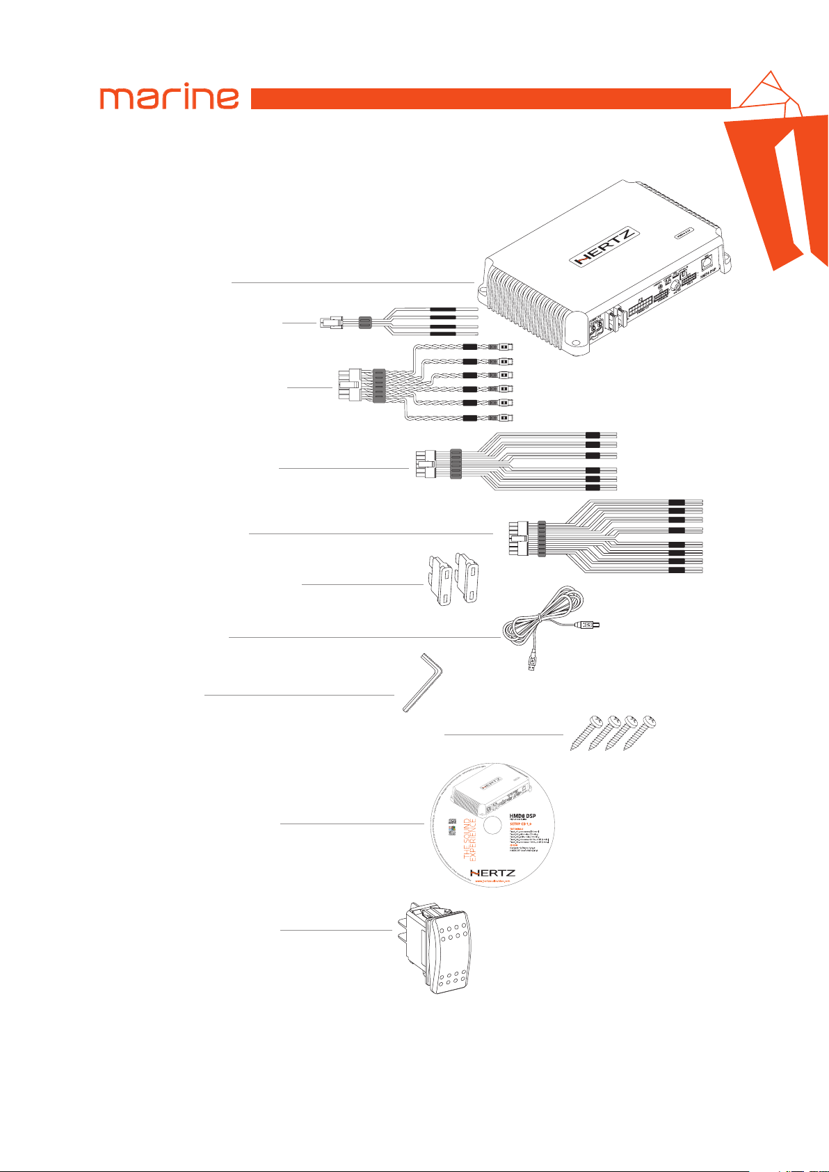
2. PACKAGE CONTENTS
- HMD8 DSP amplifier
- Multipolar cable, Rem/Control:
- Multipolar cable, Input Pre-IN:
- Multipolar cable, Hi-level Input:
- Output Multipolar cable:
- 2 - 30 A (12V) replacement fuse:
or
2 - 15 A (24V) replacement fuse:
CONTROL 1
CONTROL 2
REM IN
REM OUT
HMD8 DSP/
IN 6
IN 5
IN 4
IN 3
IN 2
IN 1
IN 6
IN 5
IN 4
IN 3
IN 2
IN 1
OUT 8
OUT 7
OUT 6
OUT 5
OUT 4
OUT 3
OUT 2
OUT 1
2
- 1.8 m USB cable:
- 2.5 mm hex key:
- 4 - 4.2 x 50 mm self-tapping, cross head mounting screws:
- CD ROM containing:
HMD8 DSP Software
This owner’s manual (.pdf)
Audio Test Tracks
- SWITCH for memory selection:
4
Page 5
USER’S MANUAL
UPGRADE
OFF ON
3. HMD8 DSP INSTALLATION
HMD8 DSP/
3
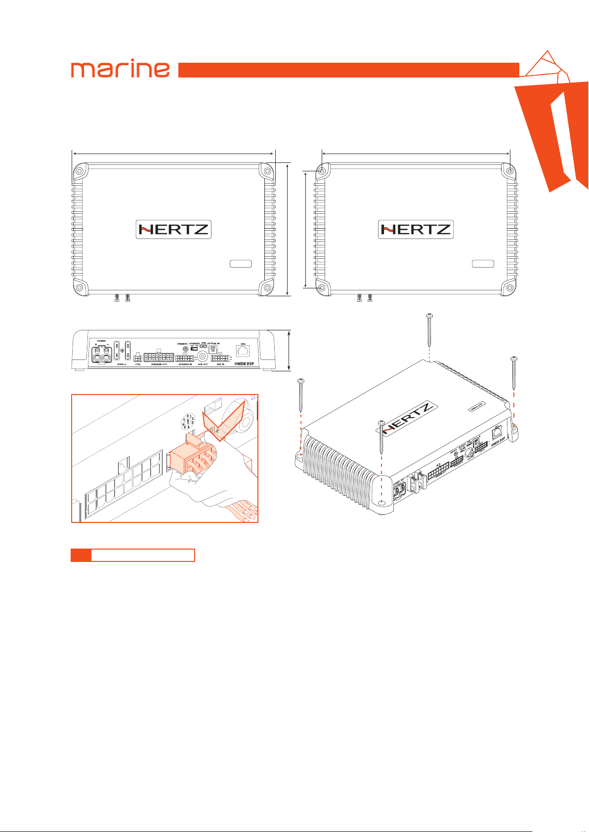
External size
243 mm / 9.56 in
.
WARNING for all cable INPUT/OUTPUT
PRESETS
OK
SPEAKER IN
Mounting size
.
159 mm / 6.25 in
139 mm / 5.47 in.
HMD8 DSP HMD8 DSP
224 mm / 8.81 in.
How to mount
48 mm / 1.8 in.
SUB OUT
SPEAKER OUT
3.1 DEVICE INSTALLATION
The following represents the sequence for a typical amplifier installation, using an aftermarket source unit.
Additional steps and different procedures may be required in some applications.
If you have any questions, please contact your authorized Hertz dealer for assistance.
1. Disconnect the negative battery post connection and secure the disconnected cable to prevent accidental re-connection
during installation. This step is not optional!
2. Run positive and negative power wire from the battery location to the amplifier mounting location, taking care to
route it in such a way that it will not be damaged and will not interfere with vessel operation.
3. Connect power wire to the positive battery post.
4. Connect negative power wire to the negative battery post. Use the same size power wire as the wire connected to
the positive power supply connection.
5. Run signal cables and remote turn-on wire from the source unit to the amplifier mounting location. Run also the
control cables for memory switch.
6. Run speaker wire from the speakers to the amplifier mounting location.
7. Securely mount the amplifier using appropriate hardware.
8. Connect the remote turn-on wire and the positive and negative power wires to the amplifier’s power connector plug.
9. Connect the input cables to the amplifier.
10. Connect the speaker wires to the speaker connector.
11. Carefully review the amplifier’s control settings to make sure that they are set according to the system’s needs.
At this point you can turn on the amplifier and start the software configuration, according to the design of your audio system.
5
Page 6
USER’S MANUAL
4. CONNECTION PANEL - DESCRIPTION
HMD8 DSP
HMD8 DSP/
13
4
8
UPGRADE
OFF ON
SUB OUTCTRL SPEAKER IN PRE IN
USB
11
OPTICAL IN
DRC
12
HMD8 DSP
6
POWER.
1
POWER
2
FUSE x 2
PRESETS
SPEAKER OUT
31 74 5
9 10
0
1
7
2
6
5
3
4
+ Power (11-15 VDC or 22-34 VDC according to POWER silk-screened value): connection terminal for power supply
positive pole.
The jack accepts a stripped cable up to 15mm / 0.6” with maximum section of 8 AWG (∅ 3,2mm / 0.12”). For better
power transfer we recommend using cables with the largest possible cross-section and with the same cross-section
as the cable connected to the negative pole.
- Power (Ground): connection terminal for the negative power supply pole of the amplifier. Connect here the negative
battery cable or a cable connected to the metal part of the vessel chassis. The socket will take a stripped cable up to 15mm / 0.6”
with a maximum section of 8 AWG (∅ 3,2mm / 0.12”). For better power transfer, we recommend using cables with
the largest possible section and with the same section as the cable connected to the positive pole. In order to correctly
connect the ground (-), use a screw that is already present on the metal part of the vessel; if necessary, remove any
paint residue or grease, using a tester to make sure there is continuity between the negative terminal (-) on the battery
and the mounting point. If possible, connect all of the grounds on the audio components to the same grounding point.
This helps to reduce most of the interference than can occur in audio reproduction.
WARNING: make sure the connection polarity is as indicated on the terminals. A misconnection may result in
damage to the device. After applying power, wait at least 10 seconds before turning the device on.
6
Page 7
HMD8 DSP/
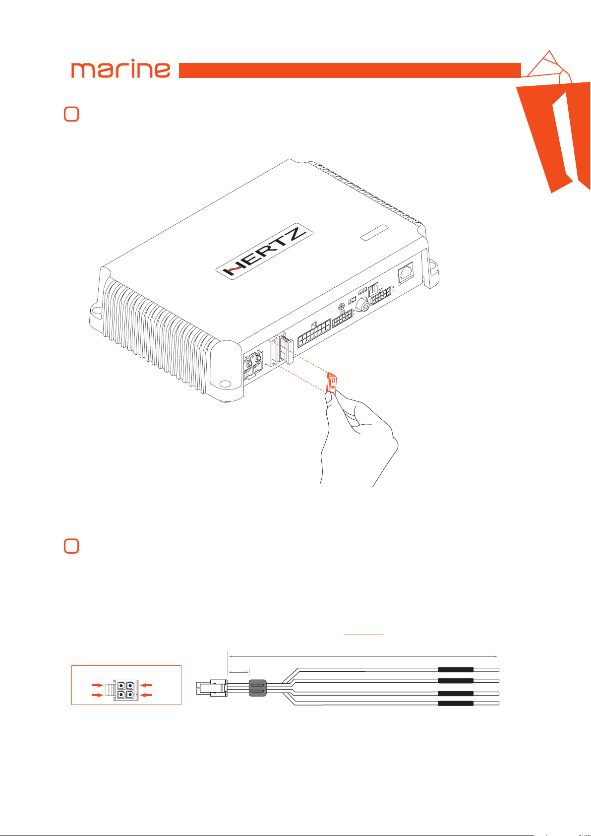
FUSE
2
USER’S MANUAL
30 A blade protection fuse for 12V power supply or 15 A blade protection fuse for 24V power supply. In case the
fuse needs to be replaced, use same type and value as the original.
P
S
D
8
D
M
H
C
R
D
N
I
L
A
C
I
T
P
O
B
S
U
E
D
A
R
N
G
O
P
U
F
F
O
S
T
E
S
E
R
P
I
R
E
K
A
E
P
S
T
U
O
R
E
K
A
E
P
V
2
1
-
R
E
W
O
P
2
E
S
U
F
S
L
R
T
C
A
0
3
x
R
P
T
U
O
B
U
S
N
DS P
D8
HM
N
I
E
4
2 X 30A
(HMD 8 DSP 12V)
or
2 x 15A
(HMD 8 DSP 24V)
Blade fuse
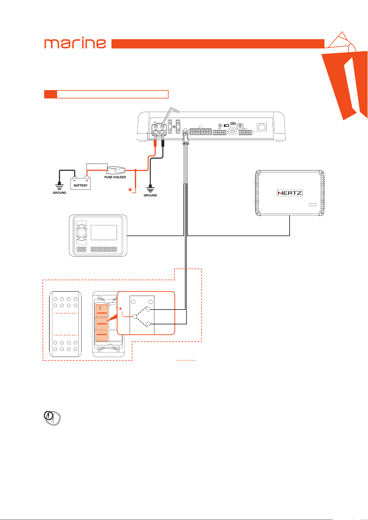
CTRL (REM IN-OUT / CONTROLS): terminals to turn on and control the HMD8 DSP.
3
- Remote IN: input to turn on the device. The voltage must be between 7 and 14.5 VDC for 12V power supply or
between 6 and 34 VDC for 24V power supply.
- Remote OUT: output to turn on other devices connected in cascade.
- CONTROL 1: it allows the memory selection. This control is active bringing the terminal to +12 V or +24 V according to
power supply voltage. More details on Memory selection switch
(see. section 5).
- CONTROL 2: it allows the memory selection. This control is active bringing the terminal to +12 V or +24 V according to
power supply voltage. More details on Memory selection switch
FRONT VIEW
blue/blackblue
pinkbrown
10 mm
0.39 in.
Wire Size: AWG 20
(see. section 5).
320 mm / 12.6 in.
CONTROL 1
CONTROL 2
REM IN
REM OUT
pink
brown
blue
blue/black
7
Page 8
HMD8 DSP/
SPEAKER OUT.
4
USER’S MANUAL
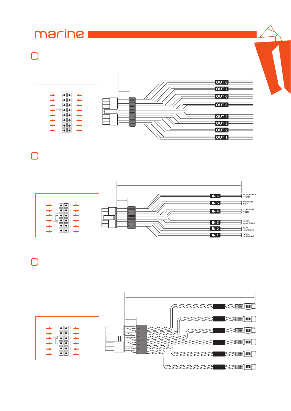
HMD8 DSP is provided with a 16 pole multipolar connector to manage the power output signals.
320 mm / 12.6 in.
FRONT VIEW
OUT 1 +
OUT 2 +
OUT 3 +
OUT 4 +
OUT 5 +
OUT 6 +
OUT 7 +
OUT 8 +
SPEAKER IN.
5
OUT 1 -
OUT 2 -
OUT 3 -
OUT 4 -
OUT 5 -
OUT 6 -
OUT 7 -
OUT 8 -
HMD8 DSP is provided with a 12 pole multipolar connector to manage the input signals. Connect up to a maximum
of 6 input channels using the multipolar connector supplied. The signal to be applied must have a value ranging
between 2.2 and 22 Vrms. Such input channels can be then customized using the configuration software.
10 mm
0.39 in.
Wire Size: AWG 16
4
+
+
+
-
+
-
+
+
+
+
-
320 mm / 12.6 in.
white
gray
green
purple
blue
orange
PRE IN
6
FRONT VIEW
white/black
gray/black
green/black
purple/black
blue/black
orange/black
10 mm
0.39 in.
Wire Size: AWG 20
HMD8 DSP is provided with a 12 poles multipolar connector to manage the PRE IN input signals to interface head
units featuring a PRE OUT output. Connect up to a maximum of 6 input channels using the multipolar connector
supplied. The signal to be applied must have a value ranging between 0.6 and 6 Vrms. Such input channels can be
then customized using the configuration software.
320 mm / 12.6 in.
IN 6
white
gray
green
purple
blue
orange
FRONT VIEW
10 mm
0.39 in.
white/black
gray/black
green/black
purple/black
blue/black
orange/black
IN 5
IN 4
IN 3
IN 2
IN 1
8
Page 9
HMD8 DSP/
SUB OUT.
7
USER’S MANUAL
Pre-amplified output subject to low pass filtering optimized to drive a mono amplifier for an external subwoofer or
active subwoofer.
OPTICAL IN.
8
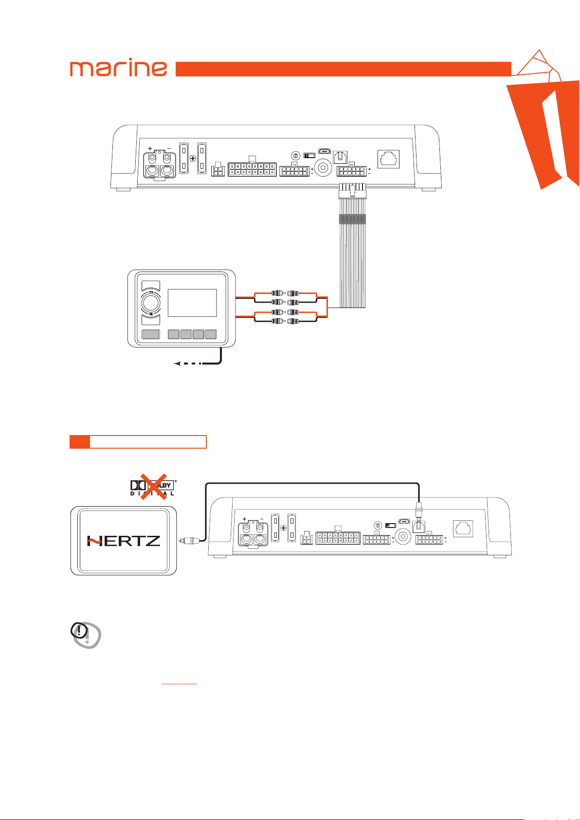
HMD8 DSP accepts at its input PCM signals up to 192 kHz / 24 bit sampling frequency rate. Connect a fiber optic cable
with a TOSLINK connector.
Remark: DOLBY DIGITAL (AC3) multi-channel signals coming from audio/video sources (such as the audio of a film in DVD)
or DTS can not be reproduced.
PRESET.
9
HMD8 DSP features 7 setups preloaded in its memory, identified by the numbers 1 to 7 of the selector. They allow
the product to be used without the need to connect it to a PC.
WARNING: Make sure you have connected the speakers according to the scheme of the selected preset
before turning the amplifier on.
Remark: when using one of the 7 presets, communication via USB is inhibited and the configuration software is unable
to detect the device even if it is connected to the PC.
By turning the selector to position 0, the device is fully configurable by the user through the configuration software
via USB connection.
UPGRADE switch.
10
Switch ON allows the product to be updated in BOOT LOADER mode.
Micro USB.
11
USB micro receptacle to connect the product to a PC in order to manage the functions using the configuration
software. The connection is USB 1.1/2.0/3.0 compatible.
DRC.
12
Terminal for future use.
4
LOGO STATUS.
13
HMD8 DSP is provided with a built-in control that manages its status and protects the circuits and connections to the
speakers. The logo on the HMD8 DSP top cover will change its status in case of any possible product malfunctions.
A WHITE logo means:
HMD8 DSP is on.
Flashing RED/WHITE logo means:
The “UPGRADE MODE” switch on the product is set to “ON” position, or the product Firmware is being updated.
Flashing RED logo means:
- HMD8 DSP temperature reached 75° C and the thermal protection was triggered. It will start operating again at
around 70° C.
RED logo flashing twice every second means:
- Output overload. The red LED flashes when the output load goes below the minimum allowed capacity of about
2Ω impedance. The LED lights up without flashing, activating the protection if the problem persists. When
listening to music, if the acoustic reproduction stops for a few seconds, check if the red amplifier LED is flashing.
This means there was an overload. Turn the amplifier off and check the speakers and wirings. This protection is
self-restoring.
- Speaker wiring anomaly. The red LED flashes when a terminal on the speaker goes in short-circuit. When
listening to music, if the acoustic reproduction stops for a few seconds, check to see if the red amplifier LED
is flashing; this means there was a short circuit between the two terminals. Turn off the amplifier and check the
speakers and wiring. This protection is self-restoring.
RED logo flashing four times every second means:
- “OVER VOLTAGE” protection activation, due to the fact that the battery voltage is higher than
18V (for HMD8 DSP 12V); 36V (for HMD8 DSP 24V) .
The product will turn off after 3 minutes.
RED logo means:
- Product internal fault. Please contact an authorized service centre. The product will turn off after 3 minutes.
9
Page 10
USER’S MANUAL
TOP WIEW
1
CTRL2
3
CTRL1
2
5. CONNECTIONS
5.1 POWER SUPPLY AND REMOTE TURN ON
HEX KEY 2,5 mm
HMD8 DSP/
5
Max 20 cm / 7.9 in.
(Not provided)
to memory
selection switch
HEAD UNIT
VOL
SEL
MEMORY SELECTION SWITCH
Memory 3
15 mm / 0.6 in.
8 AWG Max
REMOTE OUT
POWER
FUSE x 2
blue REM IN
SPEAKER OUT
PRESETS
0
1
7
2
6
5
3
4
UPGRADE
OFF ON
SUB OUTCTRL SPEAKER IN PRE IN
USB
OPTICAL IN
DRC
HMD8 DSP
EXTERNAL SUBWOOFER
AMPLIFIER (Optional)
HMD1
REM IN
blue/black REM OUT
brown CONTROL 2
pink CONTROL 1
Memory 1
8
1
2 5
7
4
3 6
Memory 2
BOTTOM WIEW
(see sec. 5.2)
How to turn HMD8 DSP on and off
HMD8 DSP can be turned on/off by connecting the REMOTE IN terminal with a Remote Out signal coming from an
after market audio source. When it is on the logo is white.
WARNING: select the version of the HMD8 DSP (12 V or 24 V) which has the same power supply voltage as
the battery installed on the vessel.
10
Page 11
USER’S MANUAL
1
CTRL2
3
CTRL1
2
HMD8 DSP
HMD8 DSP/
5.2 MEMORY SELECTION SWITCH
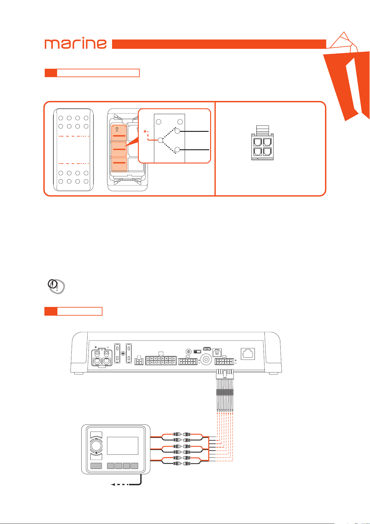
Together with the amplifier, a three-position switch is provided for manual selection of memories. The connection
scheme is shown in the image below.
5
Memory 3
Memory 1
TOP WIEW
Memory 2
8
1
2 5
3 6
BOTTOM WIEW
7
4
CONTROL CONNECTION CABLE
Brown CTRL 2.
Pink CTRL 1.
FRONT VIEW CONNECTOR
REM IN Blue
REM OUT Blue/Black
Connection notes
• The CTRL 2 wire of the control cable is connected to terminal 1 of the memory switch.
• The CTRL 1 wire of the control cable is connected to terminal 3 of the memory switch.
• The terminal 2 of the memory switch must be connected to power supply voltage (+12 V or +24 V).
Memory selection switch positions
• Central position: Memory 1 is selected.
• Pressing the bottom of the switch: Memory 2 is selected.
• Pressing the top of the switch: Memory 3 is selected.
Remark: with the memory selection switch at least one memory is always selected.
WARNING: when the amplifier is connected to the PC via the USB cable, the control for the memories selection is
performed exclusively by the configuration software: the memory selection switch is automatically disabled.
It is re-enabled to the selected position of the memory key once you exit the PC software.
5.3 INPUT SIGNALS
1. PRE INPUT ZONE 1 + ZONE 2 + SUB
POWER
After market Source
to REMOTE IN
FUSE x 2
REMOTE
out
SPEAKER OUT
ZONE 1
ZONE 2
SUB
PRESETS
6
L
R
L
R
L
R
7
5
0
1
3
4
UPGRADE
OFF ON
2
IN 1
IN 2
IN 3
IN 4
IN 5
IN 6
USB
OPTICAL IN
SUB OUTCTRL SPEAKER IN PRE IN
DRC
HMD8 DSP
11
Page 12
USER’S MANUAL
2. PRE INPUT ZONE 1 + ZONE 2
HMD8 DSP/
5
POWER
After market Source
to REMOTE IN
HMD8 DSP
FUSE x 2
REMOTE
out
SPEAKER OUT
ZONE 1
ZONE 2
USB
OFF ON
SUB OUTCTRL SPEAKER IN PRE IN
OPTICAL IN
DRC
HMD8 DSP
UPGRADE
PRESETS
0
1
7
2
6
5
3
4
L
R
L
R
IN 1
IN 2
IN 3
IN 4
5.4 DIGITAL OPTICAL IN INPUT
OPTICAL FIBER
TOSLINK connector
POWER
FUSE x 2
PRESETS
SPEAKER OUT
UPGRADE
0
1
7
2
6
5
3
4
USB
OFF ON
SUB OUTCTRL SPEAKER IN PRE IN
OPTICAL IN
DRC
HMD8 DSP
PCM Stereo signal, max 192 kHz / 24 bit
WARNING: the digital input accepts up to 192 kHz / 24 bit stereo PCM signals. So DOLBY DIGITAL (AC3) multi-channel signals
output of these devices will therefore have to be set in STEREO mode for the signal to be reproduced.
coming from audio/video sources (such as the audio of a film in DVD) or DTS can not be reproduced. The
How to select the OPTICAL input:
Using the PC software
(see sec. 6.4.2);
and “Finalize” the device.
12
Page 13
5.5 OUTPUT SIGNALS
USER’S MANUAL
HMD8 DSP/
5
POWER
16: White OUT 1+
8: White/Black OUT 1-
15: White OUT 2+
7: White/Black OUT 2-
14: White OUT 3+
6: White/Black OUT 3-
13: White OUT 4+
5: White/Black OUT 4-
12: White OUT 5+
4: White/Black OUT 5-
11: White OUT 6+
3: White/Black OUT 6-
FUSE x 2
SPEAKER OUT
PRESETS
6
2
7
5
0
1
2
3
4
UPGRADE
OFF ON
USB
OPTICAL IN
SUB OUTCTRL SPEAKER IN PRE IN
DRC
HMD8 DSP
HMD1
10: White OUT 7+
2: White/Black OUT 7-
9: White OUT 8+
1: White/Black OUT 8-
1
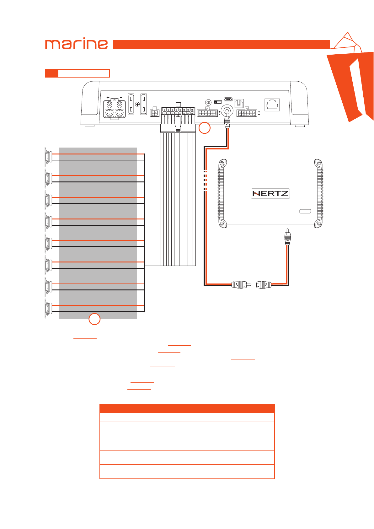
1. HMD8 DSP provides 8 amplified outputs. Through the PC Software, each output channel is provided with the
following
- the dedicated audio channel send of the mixer
- a digital time delay line and distance setting
- an electronic crossover with 5 filter types and phase inversion activation
- a 10 pole graphic/parametric equalizer
In addition each output channel can:
- be assigned to a listening zone
- belong to one or more groups
2. HMD8 DSP features a preamplified output (4 V Rms max.) SUB OUT that exclusively controls a mono amplifier for subwoofer,
or one active subwoofer to amplify the sound system. This output corresponds to “OUT 9” PC Software graphic interface.
(see sec. 6.4.4)
:
(see sec. 6.4.7)
(see sec. 6.4.8)
(see sec. 6.4.10)
(see sec. 6.4.6)
(see sec. 6.4.5)
;
;
;
CH 1 ÷ CH 8 AMPLIFIED OUTPUT CHANNELS CONFIGURATION
POWER CHANNEL CONFIG
STEREO MODE BRIDGE MODE
CH1 85 W @ 4 Ohm / 130 W @ 2 Ohm
CH2 85 W @ 4 Ohm / 130 W @ 2 Ohm
CH3 85 W @ 4 Ohm / 130 W @ 2 Ohm
CH4 85 W @ 4 Ohm / 130 W @ 2 Ohm
CH5 85 W @ 4 Ohm / 130 W @ 2 Ohm
CH6 85 W @ 4 Ohm / 130 W @ 2 Ohm
CH7 85 W @ 4 Ohm / 130 W @ 2 Ohm
CH8 85 W @ 4 Ohm / 130 W @ 2 Ohm
CH1+ / CH2- 260 W @ 4 Ohm
CH3+ / CH4- 260 W @ 4 Ohm
CH5+ / CH6- 260 W @ 4 Ohm
CH7+ / CH8- 260 W @ 4 Ohm
(see sec. 6.4.9)
;
13
Page 14
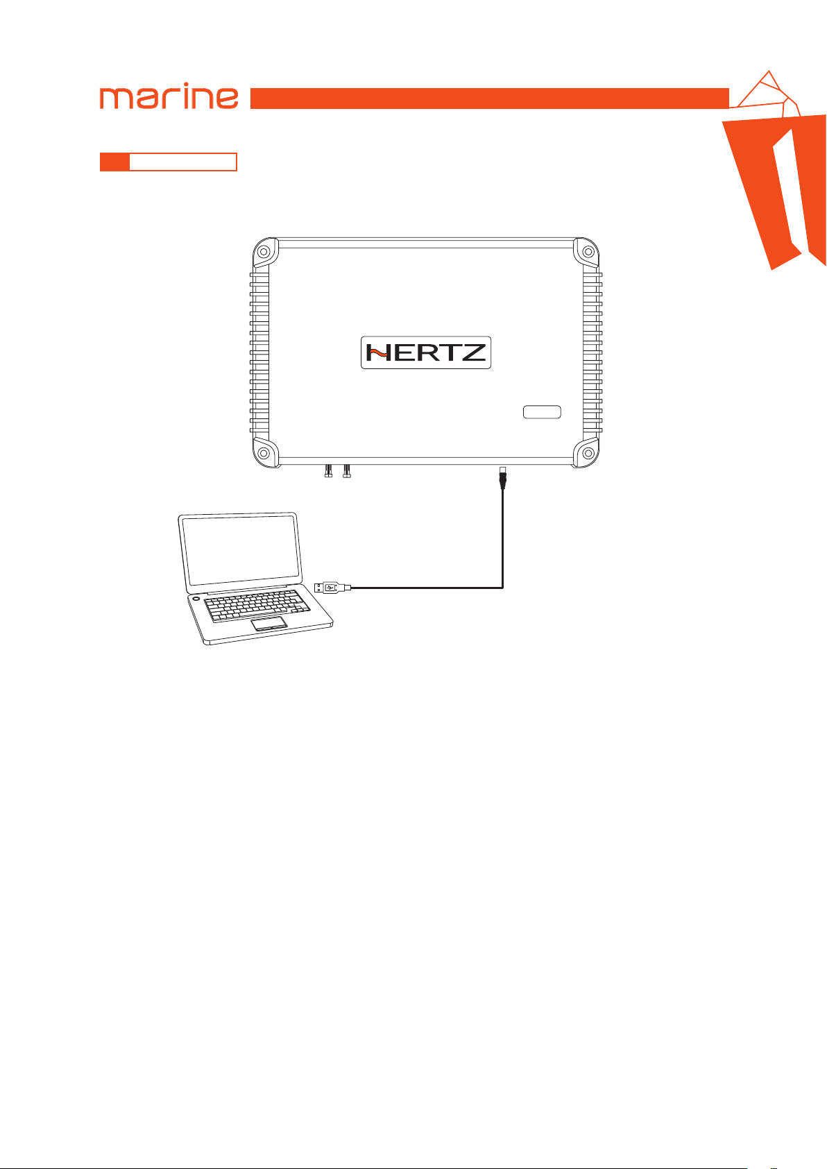
USER’S MANUAL
5.6 PC CONNECTION
1. HMD8 DSP connection with PC
HMD8 DSP
HMD8 DSP/
5
USB cable
(provided)
14
Page 15
USER’S MANUAL
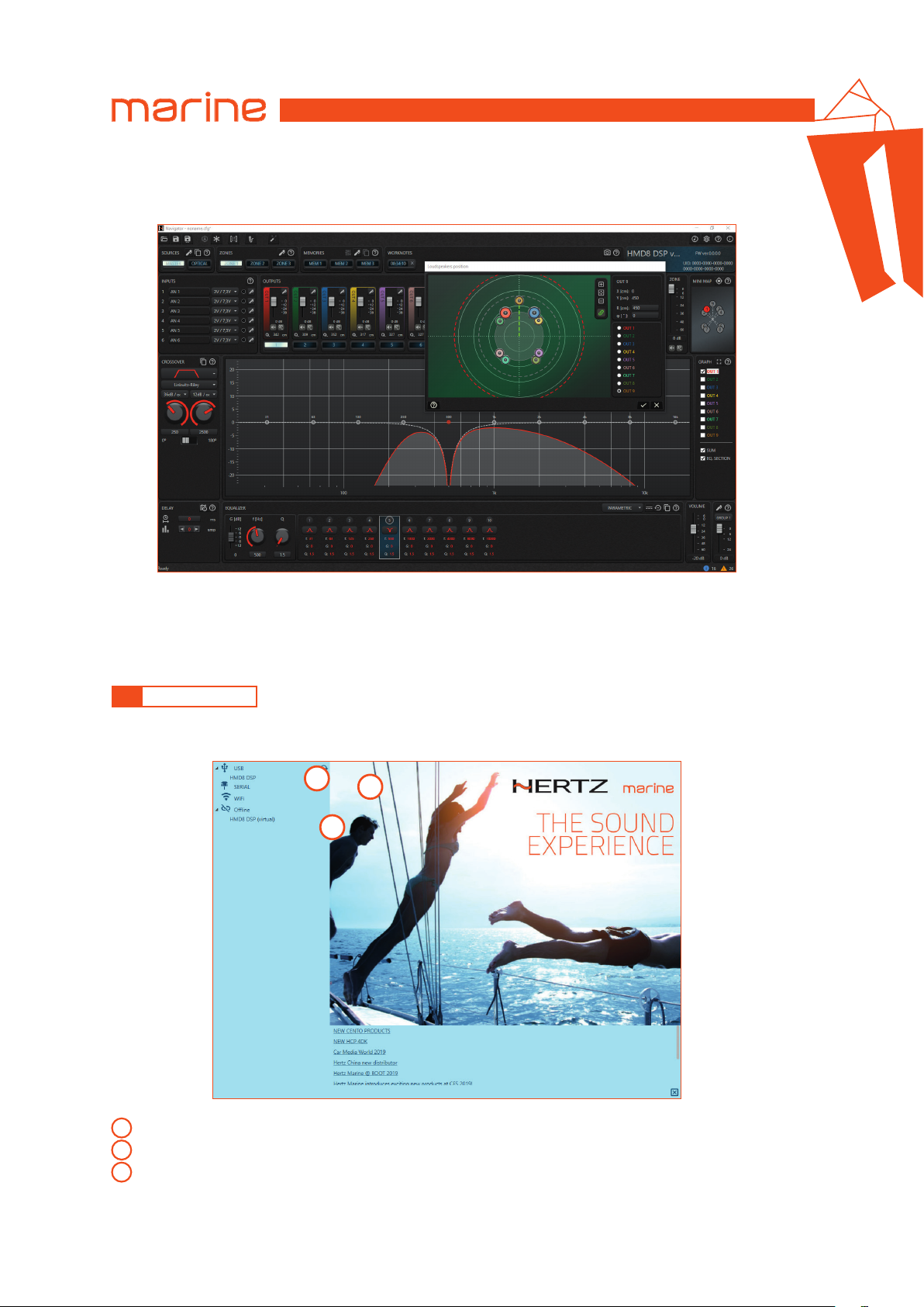
6. CONFIGURATION SOFTWARE
This section describes the main features of the configuration software: Navigator.
HMD8 DSP/
6
The software was designed to be adopted by all products with onboard DSP in the Hertz marine catalog and future
ones: when you connect the device to the software, it automatically configures itself to display the interface of that
specific device connected.
Navigator can also be used without a real physical device, as it provides a series of virtual devices that fully reflect the
respective real counterparts.
6.1 LINK TO DEVICE
When you start the software, an initial screen appears, listing all the devices you can connect to it.
You can see an example in the image below:
1
3
2
real DEVICE connected to the PC: the software detected an HMD8 DSP device connected via USB to the PC;
1
virtual DEVICE: it is a virtual model of a real device;
2
refresh button: update all the lists.
3
Once the device has been selected, the software communicates with it and displays the current configuration.
Remark:
the device must be switched on and connected to the PC so that it can appear in the list of the available devices.
15
Page 16
USER’S MANUAL
6.2 SAVE AND LOAD THE CONFIGURATION
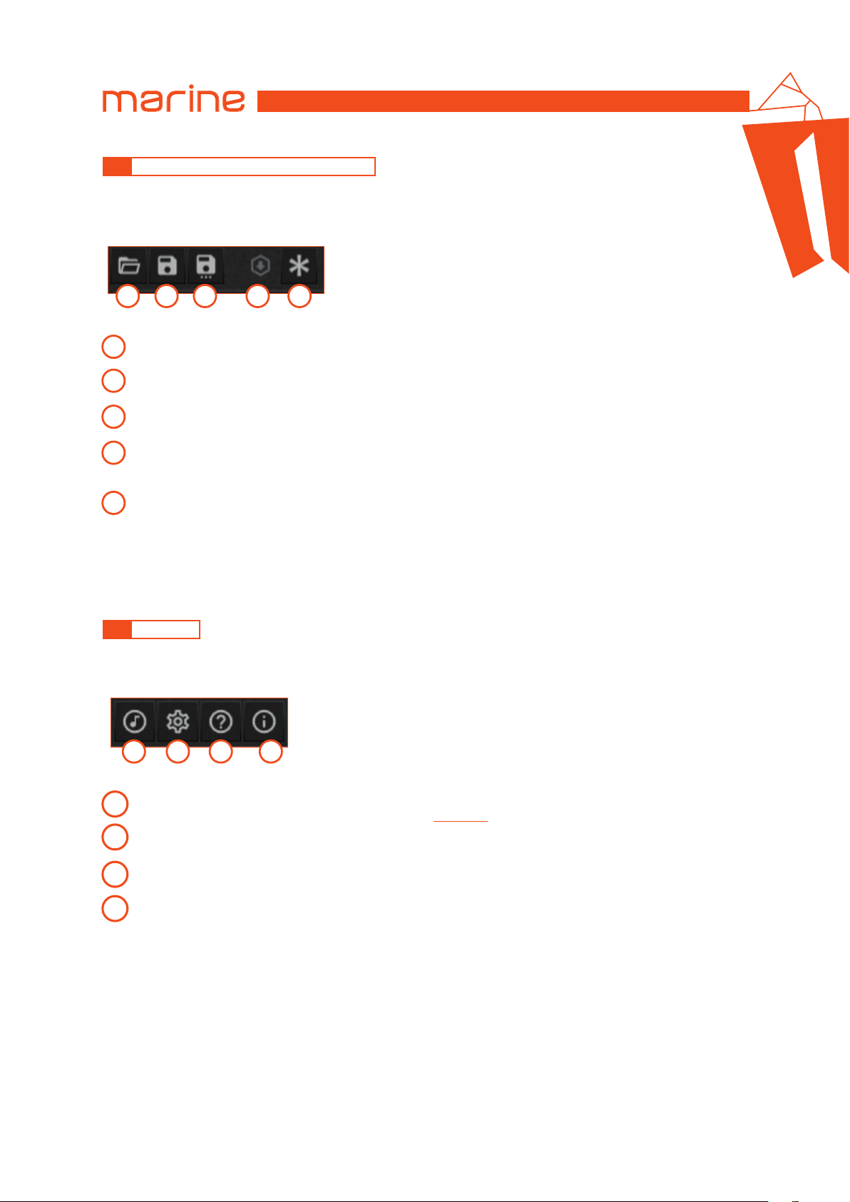
The software provides the ability to save the current configuration to a file, upload one already saved on your PC
and other important features.
These are available on the top command bar, as shown in the image below.
HMD8 DSP/
6
1 2 3 4 5
OPEN
1
Load configuration from a file saved on the PC.
SAVE
2
Save the current configuration to a file on the PC.
SAVE AS
3
Save a named copy of the current configuration to a file on the PC.
FINALIZE
4
Writes the current status of the device to memory, the current configuration becomes permanent and is retained
after power down.
DEVICE RESET TO FACTORY DEFAULT
5
Clear the device memory containing the user settings; it returns to the default condition. Presets are not cleared.
Remark: in the default condition, the device does not reproduce any sound in the output channels: this is because
the audio mixer (the routing of the inputs to the outputs) has a zero value for all the sends.
6.3 SETTINGS
The software provides the ability to change general settings. The icons for general settings are available on the top
right command bar, as shown in the image below.
1 2 3 4
AUDIO SETTINGS
1
access the audio settings panel. See Real time analysis
SETTINGS
2
access the general settings panel of the configuration software.
HELP
3
to open the user guide.
INFO
4
access the panel containing information about the software.
(see sec. 6.5.3)
.
16
Page 17
USER’S MANUAL
HMD8 DSP/
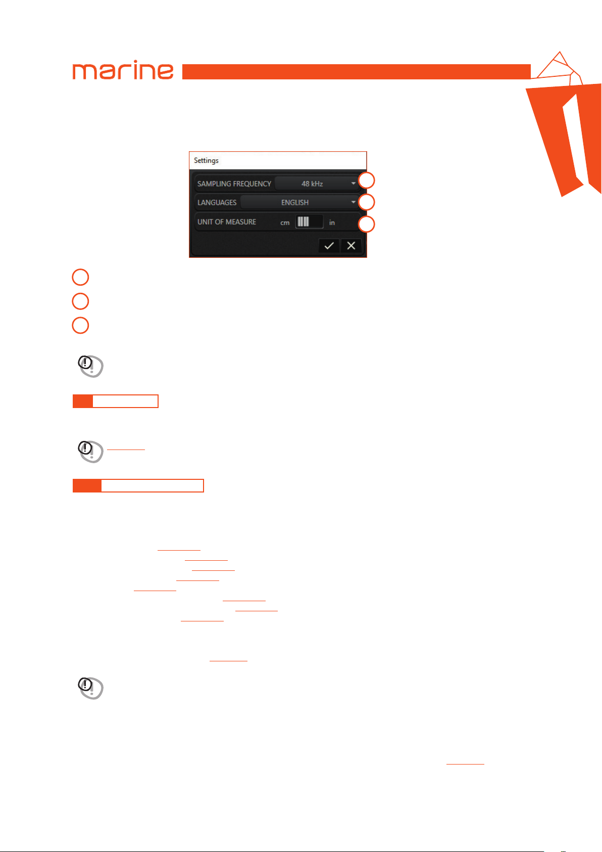
Settings
The image below shows the general settings panel:
1
2
3
Sampling frequency: allows you to set the sampling frequency used by the audio processor (DSP).
1
Language: allows you to set the software interface language.
2
Unit of measure: allows you to set the unit of measurement choosing between centimeters (cm) or inches (in).
3
WARNING: the DSP mounted on this device is capable of processing the signal only at 48 kHz.
6
6.4 AUDIO SETUP
The following paragraphs describe the functions to adjust the system and its acoustic fine tuning.
WARNING: we recommend performing the various configuration tasks in the order described in the General guidelines
(see sec. 6.4.1)
.
6.4.1 GENERAL GUIDELINES
To carry out a correct system configuration, it is advisable to follow a precise logical order: a thorough understanding
of all the phases necessary for the construction of the system is essential to avoid errors or, in the worst case,
damage to the components.
The following procedure describes in steps how to obtain a correct audio configuration of the amplifier.
• Sources definition
• Input channels definition
• Output channels definition
• Crossover initialization
• Mixer setup
• Output level and delay adjustment
• Crossover and equalizer configuration
• Memories configuration
(see sec. 6.4.1.1)
(see sec. 6.4.1.5)
(see sec. 6.4.1.2)
(see sec. 6.4.1.3)
(see sec. 6.4.1.4)
(see sec. 6.4.1.8)
(see sec. 6.4.1.6)
(see sec. 6.4.1.7)
6.4.1.1 SOURCES DEFINITION
First you need to identify the sources you intend to use in your system.
Give each one a meaningful name.
(see sec. 6.4.2)
WARNING: assigning the name to the elements is of great help in the specialization of your system. It is advisable to
do this for all setup elements where required, from here on out.
Disable the sources you do not intend to use.
6.4.1.2 INPUT CHANNELS DEFINITION
For each active source, assign a meaningful name to all input channels.
Disable those channels that are not used in the configuration.
Complete the configuration of each input channel by entering the sensitivity value if necessary.
(see sec. 6.4.3)
17
Page 18
USER’S MANUAL
HMD8 DSP/
6
6.4.1.3 OUTPUT CHANNELS DEFINITION
The output channels represent the points where the sound is reproduced, i.e. where the speakers are physically
connected. Ultimately, the output configuration is the one that most characterizes the audio system.
It is important to have the system project clearly in mind before starting: the type and the position of loudspeakers,
the need for bridged channels, how many listening areas must be created.
So, for each output channel:
• assign a meaningful name;
• specify if it is a bridge mode channel;
• assign the channel to a listening zone;
• if necessary assign the channel to one or more groups.
(see sec. 6.4.6)
(see sec. 6.4.5)
Disable unused channels.
At this point it is possible to define the position of each speaker in the respective listening area. This setting is very
important, because it provides essential information to the software for the automatic calculation of delays in order
to align the sound stage.
6.4.1.4 CROSSOVER INITIALIZATION
To avoid damaging the speakers, before starting to play the system it is important to set the crossover filter of each
output channel (for each source you intend to use) with an initial value that respects the dynamic range of each speaker.
At a later stage you can go back and adjust this setting to get the best result.
(see sec. 6.4.9)
WARNING: this setting is related to a particular output channel, for the currently selected source. It must therefore be
repeated for all output channels, for each source.
6.4.1.5 MIXER SETUP
Once the input and output configurations are known, the mixer can be set.
Remark: starting from the default configuration, at this point the system does not reproduce any sound yet.
We must specify how the inputs flow onto the outputs.
In the mixer, the signal of each output channel can be constructed as a weighted sum of the signals coming from the
input channels.
(see sec. 6.4.7)
WARNING: acting on the mixer, the system will start to reproduce audio. It is strongly recommended to keep the
general volume of the system at a very low level, to avoid damaging the speakers.
Remark: although it might seem obvious, it is worth keeping in mind the fact that each source has its own mixer.
6.4.1.6 OUTPUT LEVEL AND DELAY ADJUSTMENT
Now that the system is playing, you can act on the levels of the individual output channels, to balance the energy
contribution of each speaker and if necessary also the time alignment.
(see sec. 6.4.4 - 6.4.8)
Remark: it is important to bear in mind that these adjustments refer to the position in which the listening area is centered.
WARNING: output level is related to a specific output channel.
Its regulation must therefore be repeated for all output channels.
WARNING: delay adjustments are related to a specific output channel, for the currently selected source.
They must therefore be repeated for all output channels, for each source.
6.4.1.7 CROSSOVER AND EQUALIZER CONFIGURATION
This step can be done once the system is well defined.
In fact it is the optimization of the sound stage, that is a compensation of all those factors, internal and external to
the system, that ensures a correct sound reproduction.
The ultimate goal is to achieve a balanced setup, in which all the components act consistently to provide a neutral
listening experience.
(see sec. 6.4.9 - 6.4.10)
WARNING: these settings are related to a specific output channel, for the currently selected source. They must
therefore be repeated for all output channels, for each source.
18
Page 19
USER’S MANUAL
6.4.1.8 MEMORIES CONFIGURATION
The memories act on all the output channels and serve to give a particular nuance setting to the system.
Unlike the previous settings which are an essential and fixed part of the setup, the memory can be activated or
deactivated by the end user while listening.
(see sec. 6.4.11)
HMD8 DSP/
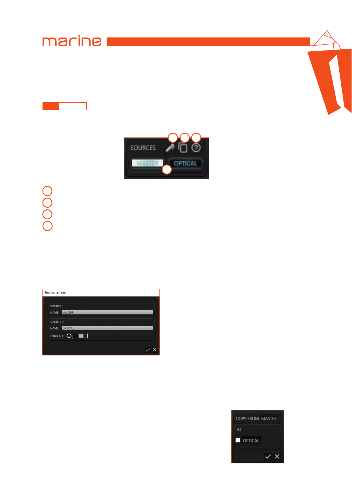
6.4.2 SOURCES
The Sources represent the devices from which to reproduce audio signals and which can be connected to the
amplifier. Based on the technical specifications, an amplifier can be connected to one or more sources. Source
selection is possible using the configuration software.
2 3 4
1
Selection button: select the source.
1
Sources settings panel: access the sources settings panel.
2
6
Copy panel: access the source copy panel.
3
Help: to open the user guide.
4
Remark: there is always a source selected. It is not possible to deselect all the sources.
Remark: it is not possible to select multiple sources at the same time.
Remark: each source has its own number of input channels.
•
SOURCES SETTINGS PANEL
The image below shows the settings panel for the sources.
The sources can be:
• renamed;
• disabled / enabled.
Remark: not all sources can be disabled: the master source is always enabled.
•
COPY PANEL
The image below shows the settings panel for the sources.
By selecting the copy destination checkbox and confirming, the
following fields will be copied for all the output channels from the
current source to the checked one:
• crossover;
• equalizer;
• delay (both the delay in milliseconds and the delay correction in samples).
19
Page 20
USER’S MANUAL
HMD8 DSP/
6.4.3 INPUT CHANNELS
The Input channels depend directly on the currently selected source. Each source has its number of inputs and its
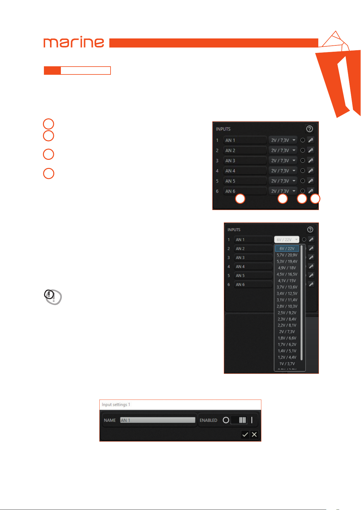
type of inputs. In this amplifier the input channels are analog for the MASTER source and digital for the OPTICAL
source.
•
ANALOG INPUT CHANNELS
The image below shows the inputs panel for the MASTER source.
Input channel name: this label is read-only.
1
Sensitivity: selection of the input sensitivity through the
2
drop-down menu.
Digital clip: the LED lights up if the channel saturates the
3
digital dynamic of the input converters.
Input settings panel: access the input settings panel.
4
1 2 3 4
6
The image below shows the sensitivity scale for an analog input channel: the
value at the top indicates the lowest sensitivity level; the value at the bottom
corresponds to the highest sensitivity level. The scale has double values: they
are related to the type of analog input connector used, i.e. SPEAKER IN or PRE IN.
Procedure for sensitivity adjustment:
Remark: to perform the procedure it is recommended to use the TEST track
(Track 1_sinesweep)
website
www.hertzaudiovideo.com.
on the supplied CD or downloadable from the
WARNING: the head unit level must be adjusted to the maximum
undistorted level. If the initial head unit distortion level can not
be determined, adjust the volume to approximately 80% of its
maximum. If the head unit output level is set too low, the device
may produce ground noise (hissing sound) when playing music
tracks. This is due to the low signal / noise ratio provided by the
head unit to the amplifier input. If you experience this problem,
increase the head unit volume.
Remark: after adjusting the head unit level, select the sensitivity value that
does not cause clipping on the inputs.
Step by step select an ever increasing sensitivity (i.e. decreasing numerical
values on the scale) as long as the LED of the digital clip remains off.
Remark: repeat the sensitivity adjustment operation for all the
analog inputs used.
The image below shows one of the input settings panels for the MASTER source.
The input channel can be:
• renamed;
• disabled / enabled.
20
Page 21
USER’S MANUAL
•
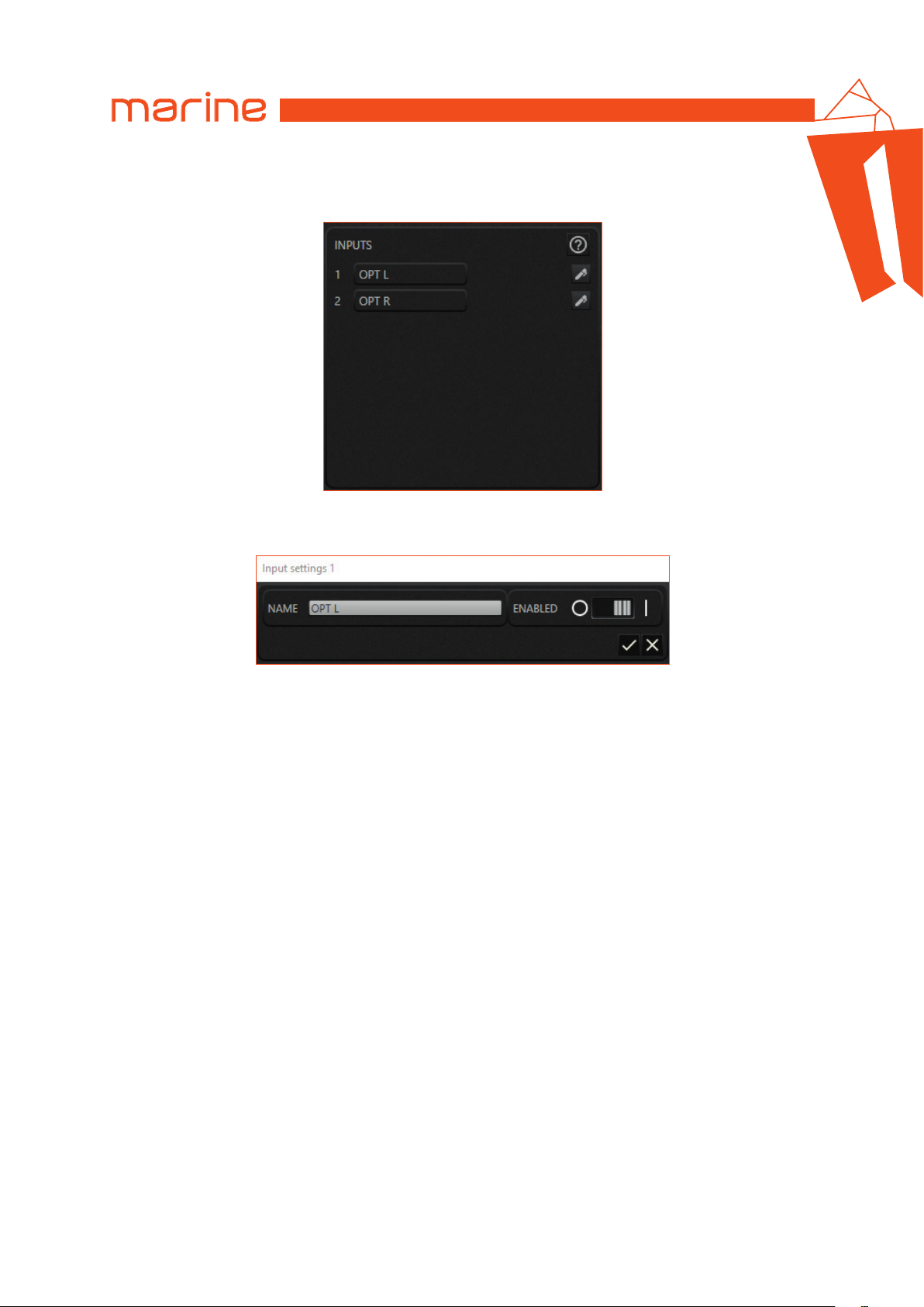
DIGITAL INPUT CHANNELS
The image below shows the inputs panel for the OPTICAL source.
Remark: for digital input channels sensitivity should not be adjusted.
The image below shows one of the input settings panels for the OPTICAL source.
HMD8 DSP/
6
The input channel can be:
• renamed;
• disabled / enabled.
21
Page 22
USER’S MANUAL
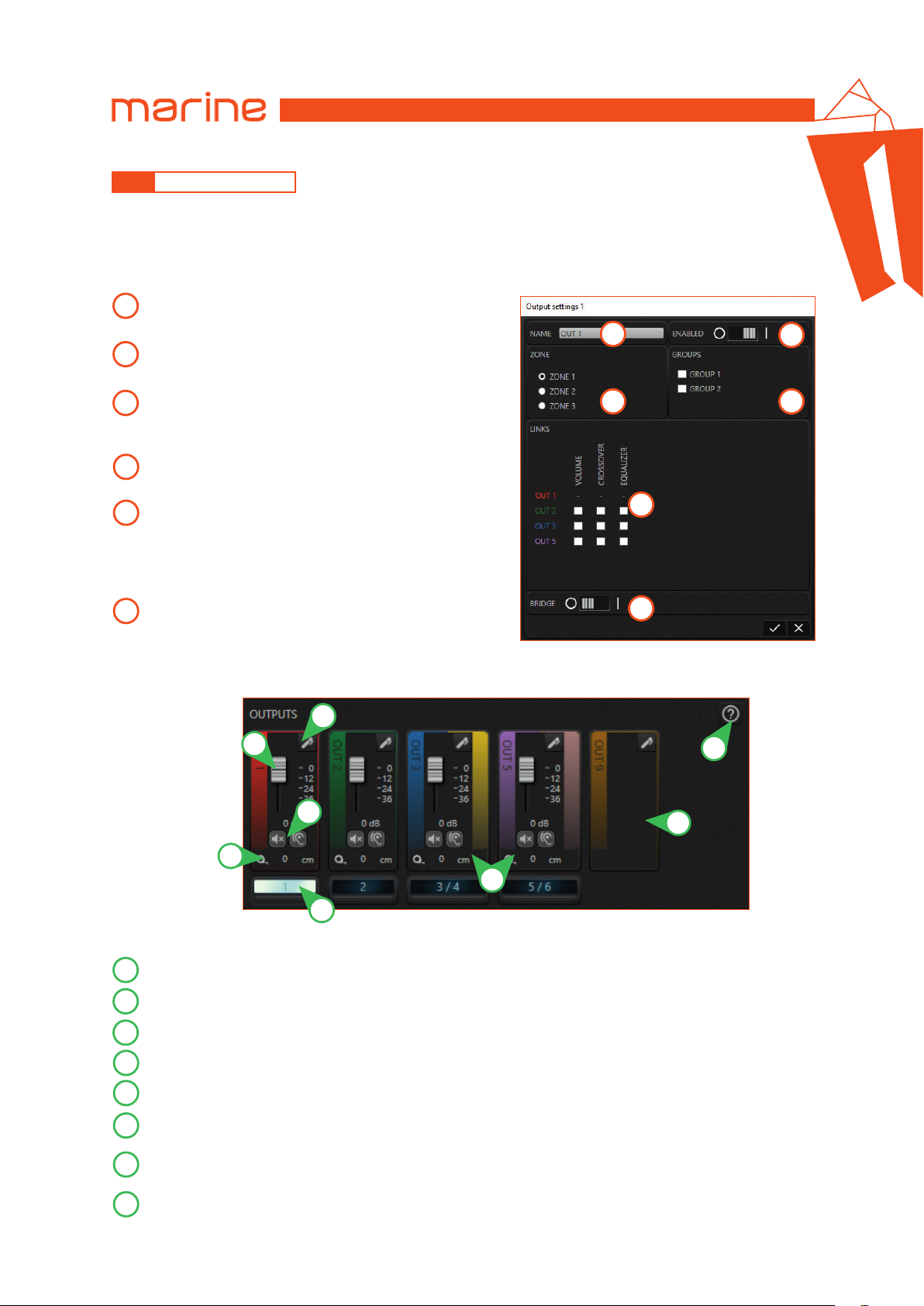
6.4.4 OUTPUT CHANNELS
The output channels represent the fundamental elements of the audio system: in the final analysis they can be
considered like installed speakers.
In the software, each channel has a color associated with it: when a specific channel is selected, the graphic interface
elements that concern it take up that same color.
The image below shows the settings panel for the selected output channel.
Output channel name: the user can customize the channel
1
by assigning it a name that describes it.
HMD8 DSP/
1
Enabled switch: it enables or disables the channel.
2
It is recommended to disable all unused output channels.
6
2
Listening zones: a channel can belong to one and only one
3
listening zone. The output panel displays only the
channels of the current selected zone.
Groups: a channel can belong to one or more groups.
4
A group of output channels shares a common group volume.
Links: it allows you to link the selected channel to other
5
channels belonging to the same zone. The effect of this link
is such that changes made to the volume, crossover or
equalizer of the selected channel are also reflected on the
linked channels.
Bridge switch:
6
configuration.
The image below describes the graphic interface behaviour related to the output channel settings.
it allows you to set the channel in bridge
5
6
5
4
3
8
7
43
2
6
1
Selection button: select the channel.
1
Loudspeaker distance: shows the distance of the speaker from the center of the listening area.
2
Mute and solo: allows you to mute the channel (mute) or to listen to it silencing all the others (solo).
3
Channel level: adjust the channel level.
4
Output settings panel: access the output settings panel.
5
Bridged channels appearance: when a channel is set to bridge mode, it logically joins the next to create one of
6
greater power. In the software a channel in bridge mode is represented in this way.
Disabled channels appearance: a disabled channel is hidden and no longer appears in any of the graphical
7
interface references.
Help: to open the user guide.
8
22
Page 23
USER’S MANUAL
6.4.5 OUTPUT CHANNEL GROUPS
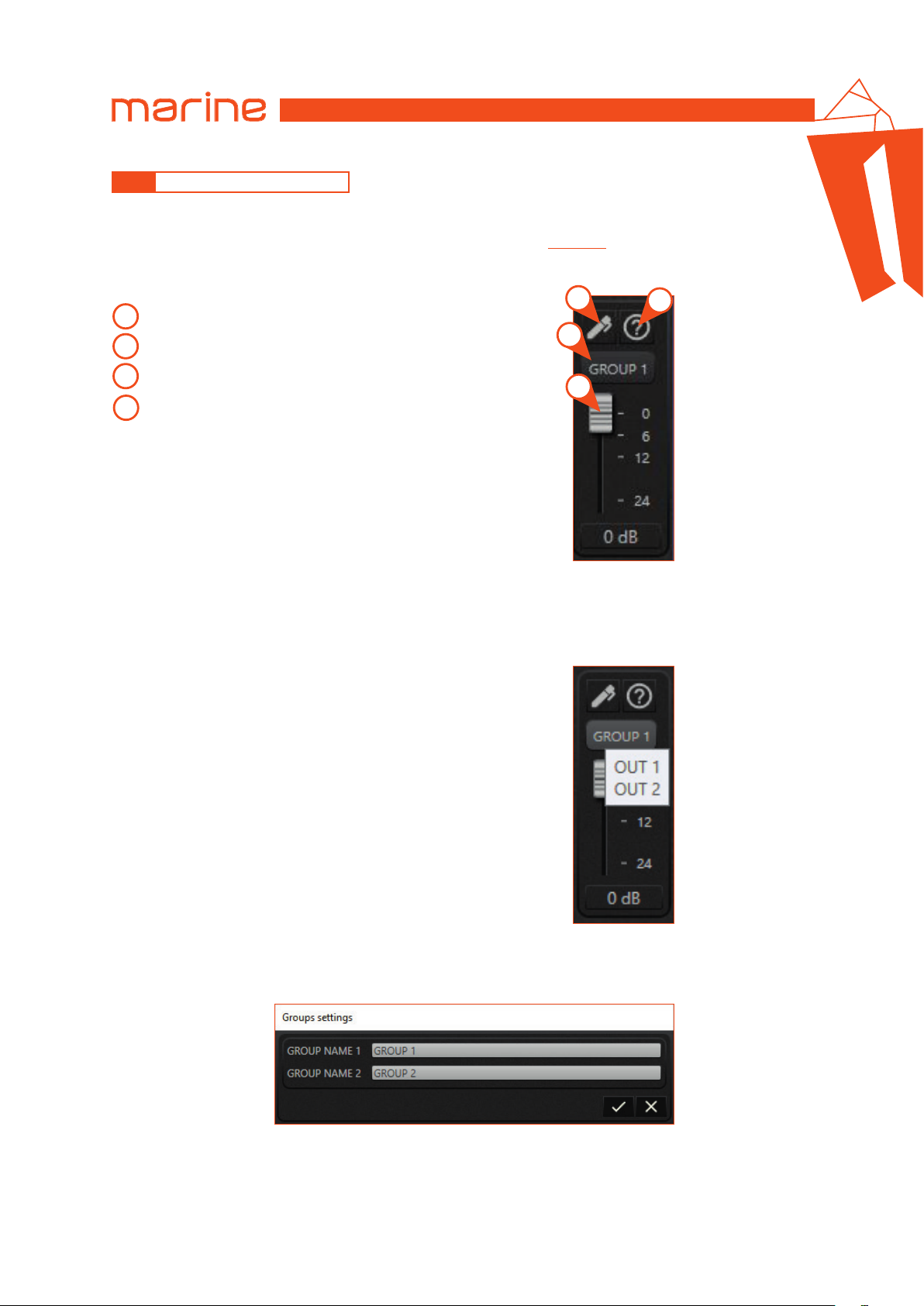
Each output channel can be associated with one or more groups. If the output channel is associated with one or
more groups, its volume will also be adjusted according to the volumes of the associated groups.
The association with the groups can be performed in the output channel
By selecting a group, you can adjust the volume in the relative panel showed in the image below:
(see sec. 6.4.4)
settings panel.
HMD8 DSP/
6
3
Group level: adjust the group level.
1
Selection button: select the group.
2
3
Groups settings panel: open the groups settings panel.
Help: to open the user guide.
4
By moving the mouse over the button to select the group, a tooltip containing the name of the channels belonging to
that group is displayed. The following image shows an example:
2
1
4
The next image shows the settings panel for the groups where you can rename them:
Remark: the most common use is to associate one or more outputs to a group to adjust the volume of the subwoofer.
23
Page 24
USER’S MANUAL
6.4.6 LISTENING ZONES
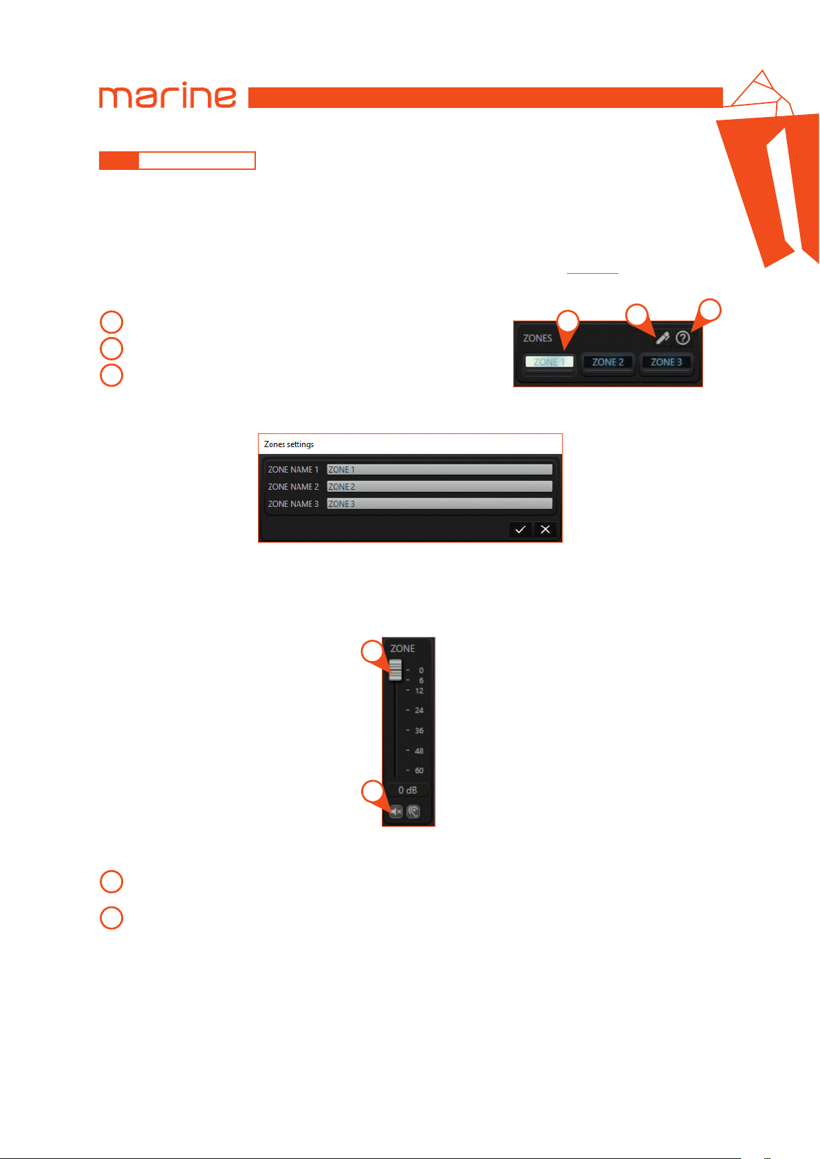
The idea behind the zones is to provide the possibility to divide the output channels when they are spatially distant
from each other so much as to consider them in different environments. The division into zones is therefore justified
if the layout of the output channels is distributed over different environments.
Remark: for this reason it is possible to associate each output channel only to one zone.
One zone may contain more than one output channel.
The association of an output channel with a zone can be performed in the output channel
The zone panel is showed in the image below.
Selection button: select the zone.
1
Zones settings panel: access the zones settings panel.
2
3
Help: to open the user guide.
Remark: the graphic interface behavior related to the output channels changes according to the selected zone.
(see sec. 6.4.4)
1
HMD8 DSP/
settings panel.
2
6
3
The image above shows the settings panel for the zones where you can rename them.
The selected zone avails of the controls shown in the image below:
2
1
Mute and solo: allows you to mute all the channels of that zone (mute) or to listen to them silencing the ones
1
belonging to other zones (solo).
Zone level: adjust the zone level.
2
24
Page 25
USER’S MANUAL
HMD8 DSP/
6.4.7 MIXER
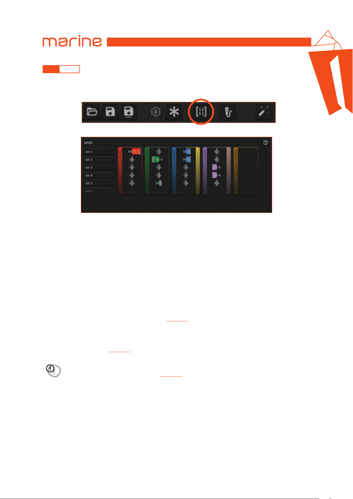
The mixer allows you to adjust the mixing percentage of the input channels on each output channel. The mixer is
accessible through the top command bar.
To exit the mixer, press the related button again.
The image below shows the graphic interface of the mixer.
6
The mixer is structured as a matrix:
• the rows feature the inputs related to the currently selected source;
• the columns feature the output channels belonging to the selected zone.
Remark: by default the mixer has all sends at 0%.
Within each output channel, identified by the colored border, the signal can be composed by clicking and dragging the
bar that indicates the percentage: this means that an input channel can go to one or more outputs.
Remark: a negative percentage of a specific input channel contribution indicates a phase inversion on that contribution.
Some use cases shown in the image above:
• if an input channel has been disabled (as the AN 6), the corresponding row in the mixer will be empty;
• if an output channel has been disabled (as the OUT 9), the corresponding column in the mixer will be empty.
• if an output channel is set in bridge mode (as the OUT 3 and OUT 5), the outline of the cluster will have two colors.
Remark: each source has its own mixer that must be set. If a source is enabled but its mixer has not been set, a
warning message will be shown on the status bar.
(see sec. 6.5.4)
Remark: if the output channels are positioned on different zones, it is necessary to select the zone to which they
belong in order to adjust the mixer.
Remark: if in the mixer there are unused input channels, or outputs that do not receive any contribution, a warning is
shown on the status bar.
(see sec. 6.5.4)
WARNING: an output channel can receive a sum of contributions greater than 100%. We strongly advise against it
because there is a risk of output digital saturation.
A warning will be shown on the status bar.
(see sec. 6.5.4)
25
Page 26
USER’S MANUAL
HMD8 DSP/
6
6.4.8 DELAYS AND DISTANCES
This setting is based on an automatic system that calculates the time needed for the sound to get from the speaker
to the listener’s ear.
Preliminary remarks
Sound moves through the air at a speed of 343 m/sec (1.125 ft/sec) at a temperature of 20 °C (68 °F). If you know
the distance from the sound emission point, you can then calculate the time the sound takes to get to the listener’s
ear. If you set the distances of the different speakers, the software will automatically change them into time (ms
-milliseconds). It does not assign a delay (0 ms) to the farthest speaker (usually the subwoofer) and progressively
growing delays as much as the other speakers get closer to the listening point, in order for all the emission points
to reach the listening point at the same time. Delay assignment according to distance calculation is theoretical.
Small variations must be applied due to small errors in distance measurement, back-wave reflections inside closed
environments and, primarily, the speaker phase problem. Two speakers reproducing two contiguous portions of the
audio signal frequency spectrum (e.g.: woofer and midrange) will simultaneously reproduce the same frequencies
in their crossing area, at an attenuated level. Due to the different nature of the speakers, they will have a phase
difference that, for a short frequency interval, acts as a time delay. By using the delay correction you can partly
correct these Phase Delay problems.
•
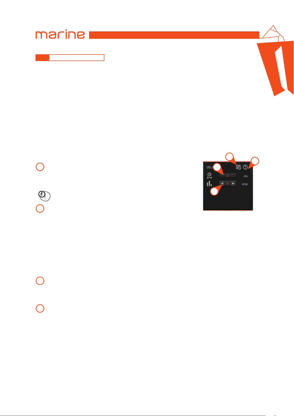
DELAYS
The image below shows the delay panel:
Delay: allows you to insert from the keyboard the delay value (in milliseconds)
1
of the current selected output channel. If the delay value entered goes beyond
the limits of the DSP, it will be set to the maximum value allowed.
3
4
1
WARNING: by editing the delay value in milliseconds and pressing enter, the delay
correction in samples is automatically reset.
Delay correction: the delay can be manually fine-tuned. A single sample at a
2
time (1 smp) can be added to or subtracted from the delay line of the current
output channel by pressing on the arrows.
Remark: 1 sample corresponds to a time delay of: 1 / Sampling Frequency [Hz] = [seconds]. The actual sampling
frequency can be read inside the global settings panel on the top right of the configuration software.
Remark: the correction of the delay in samples can be either positive or negative. In any case the starting value of the
delay to which the correction is applied, is the one visible in the text box (1). Overall, the delay plus the correction
for each output channel will always be limited between 0 ms and the maximum allowed by the DSP. Assigning a
positive value for the correction (+xx) means increasing the delay for that speaker and thus moving it farther away
from the listening point.
Likewise, assigning a negative value (-xx) means decreasing the loudspeaker delay and thus moving it closer to
the listening point.
Automatic delay calculation command: this function automatically sets the delay of the current output channel
3
starting from the position of the speaker. The next paragraph explains how to set the speakers position.
Remark: this command calculates the delay only for the currently selected output channel and for the current source.
The delay correction in samples is reset.
Help: to open the user guide.
4
Remark:
if necessary, the delay and the delay correction setting can be performed for each output channel and for each source.
2
26
Page 27
USER’S MANUAL
•
DISTANCES
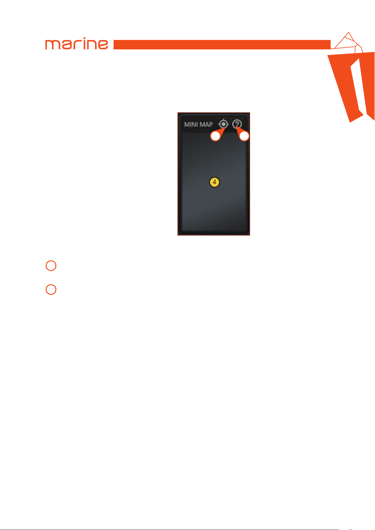
The following image shows the mini map panel and the functions related to the position of the speakers.
This panel is a miniature map showing the position of the speakers belonging to the selected zone. The icon relating
to the currently selected output channel is highlighted on the map.
HMD8 DSP/
6
1
Speaker Position Panel: to access the Speaker Position Panel.
1
Remark: the speaker position panel must be set for each zone that contains output channels.
Help: to open the user guide.
2
The mini map panel shows the positions of the speakers with respect to the center of the listening area, while the
distance value for each output channel is indicated on the output panel.
2
The distance unit of measurement (centimeters or inches) can be set in the general settings panel accessible from
the button at the top right of the configuration software.
27
Page 28
USER’S MANUAL
•
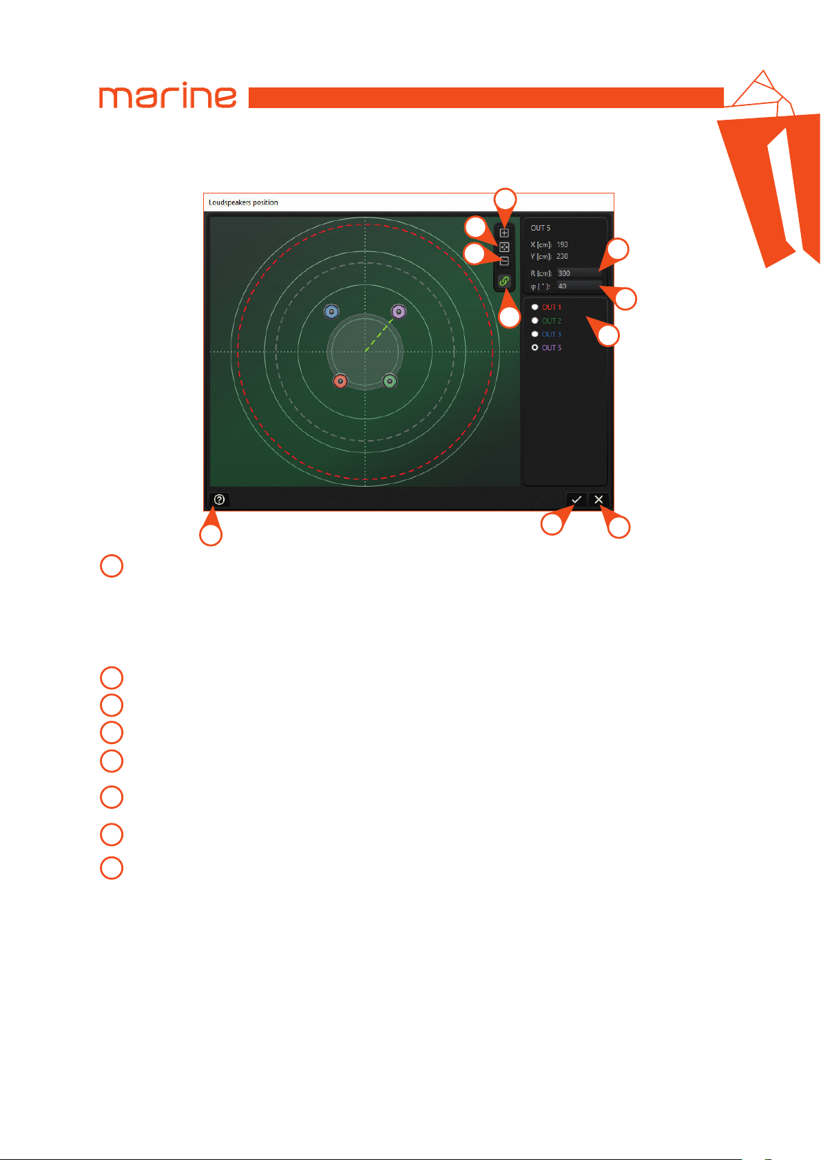
LOUDSPEAKER POSITION PANEL
The image below shows the loudspeaker position panel and its functions.
3
2
HMD8 DSP/
6
4
5
6
1
7
10
9
Maximum distance limit: this function is active by default and allows you to move the loudspeakers inside the
1
red dotted line. This limit represents the maximum distance of the speakers allowed by DSP delay lines; if all
the speakers in the map were moved away from the listening point, the red circle would increase its radius and a
gray circle will appear in the center to indicate the prohibited area within which the speakers cannot be positioned.
When activated, this function guarantees the possibility to use automatic delay calculation. However this
function can be disabled and the speakers can be positioned at any distance even outside the red circle:
the disadvantage is that the delay calculation automatism may not be able to calculate delays based on distances.
2
Zoom out: to reduce the image size.
3
Zoom fit: automatically sets the optimal view.
4
Zoom in: to enlarge the image size.
Loudspeaker distance: allows you to enter the loudspeaker distance with the keyboard. You can also click and drag
5
the loudspeaker onto the map.
Loudspeaker angle: allows you to enter the loudspeaker angle with the keyboard. You can also click and drag the
6
loudspeaker onto the map. The 0° angle is on the vertical axis upwards; the angles are positive in a clockwise direction.
Loudspeaker selection buttons: allows you to select a loudspeaker and bring it to foreground if it is hidden by other
7
loudspeakers. Initially all the loudspeakers are in the listening point.
Close button: allows you to close the loudspeaker position panel without saving the changes. The distances are
8
not updated.
8
28
Page 29
USER’S MANUAL
9
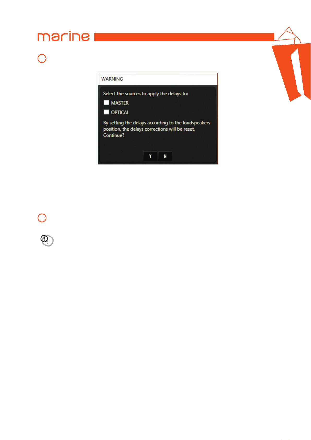
Confirmation button: it updates the speaker positions and calculates delays. The distances set are displayed on
the output channels panel. By clicking on this button, a warning message is shown as in the following image:
With a check mark in the appropriate boxes it is possible to choose the sources to which the delays should be
applied. The delays are calculated by the automatic procedure based on the position of the speakers.
Remark: after performing the automatic delay calculation, it is possible to fine tune each single output channel
through a correction in samples, acting on the delay panel.
Remark: it is recommended to use the automatic calculation of delays for all sources connected to the device. If not,
you can manually enter the delays in the delay panel.
HMD8 DSP/
Help: to open the user guide.
10
WARNING: if an output channel is moved from one zone to another, its position is preserved but it is advisable to
recalculate the delays of both zones involved.
29
Page 30
USER’S MANUAL
6.4.9 CROSSOVER
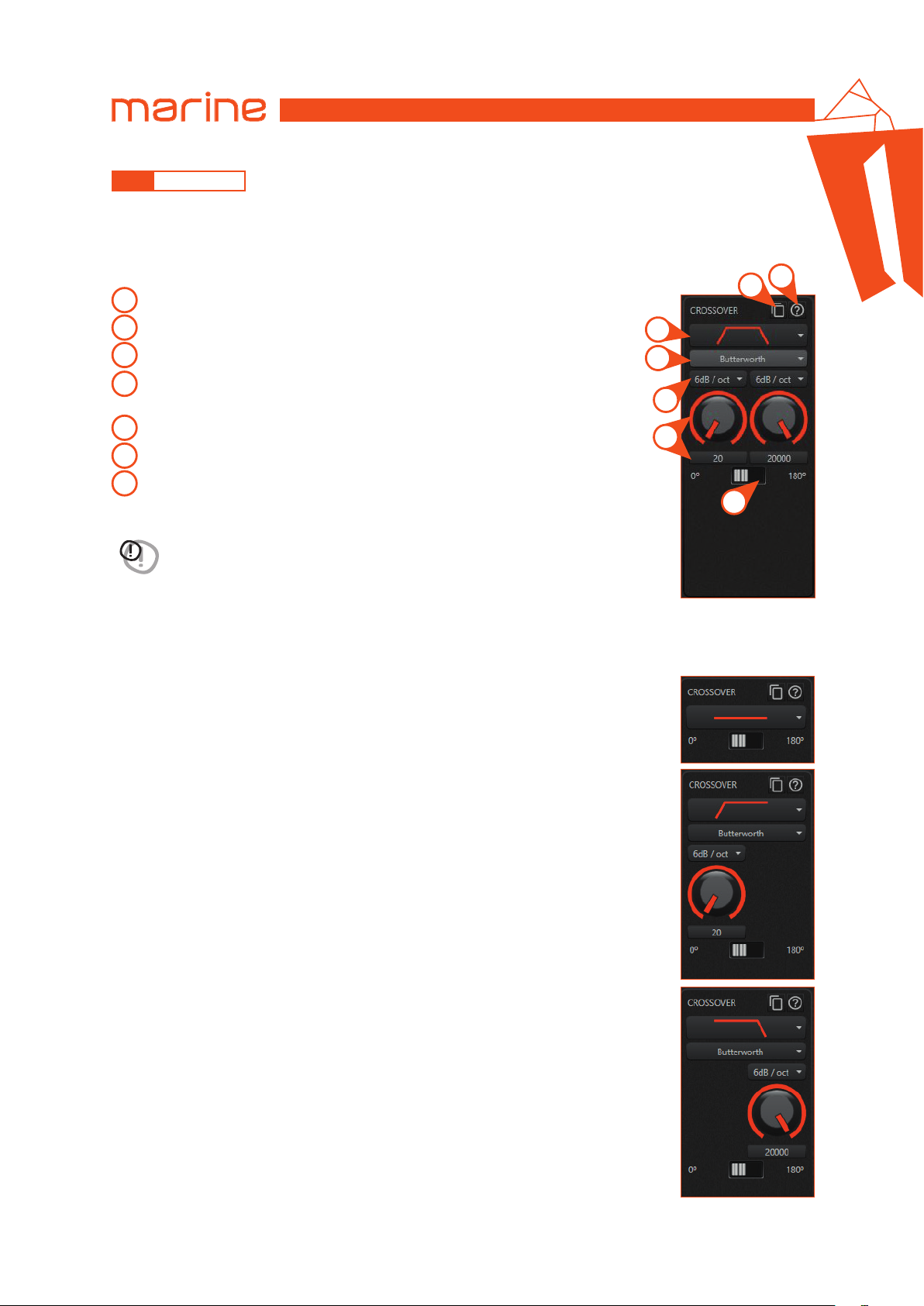
With the crossover section it is possible to set different bands for every output channel.
Remark: the output channel you are acting on is indicated by the foreground color of the crossover panel.
The image below shows the crossover parameters that it is possible to set:
Type: allows you to choose the type of crossover.
1
Name: allows you to choose the name of the crossover.
2
Slope: allows you to select the slope.
3
Frequency: allows you to set the cut-off frequency by turning the knob or
4
entering the value from the keyboard.
Phase: allows you to invert the phase of the output signal by 180°.
5
Copy panel: opens the crossover copy panel.
6
Help: to open the user guide.
7
WARNING: the parameters are linked to each other in the order shown above. When a
parameter is
changing the parameters.
Remark: the crossover of each output channel is linked to the currently selected source.
For each source it is necessary to set the crossovers on the output channels.
changed, it may cause changes to other parameters. Be careful when
1
2
3
4
HMD8 DSP/
6
7
6
5
•
TYPE
The first parameter to set is the type and the available types are:
1. FLAT
With Flat type the crossover display hides the other settings.
2. HIGH PASS
With High Pass type the crossover panel allows the name, slope and frequency selection.
3. LOW PASS
With Low Pass type the crossover panel allows the name, slope and frequency selection.
30
Page 31
USER’S MANUAL
4. BAND PASS
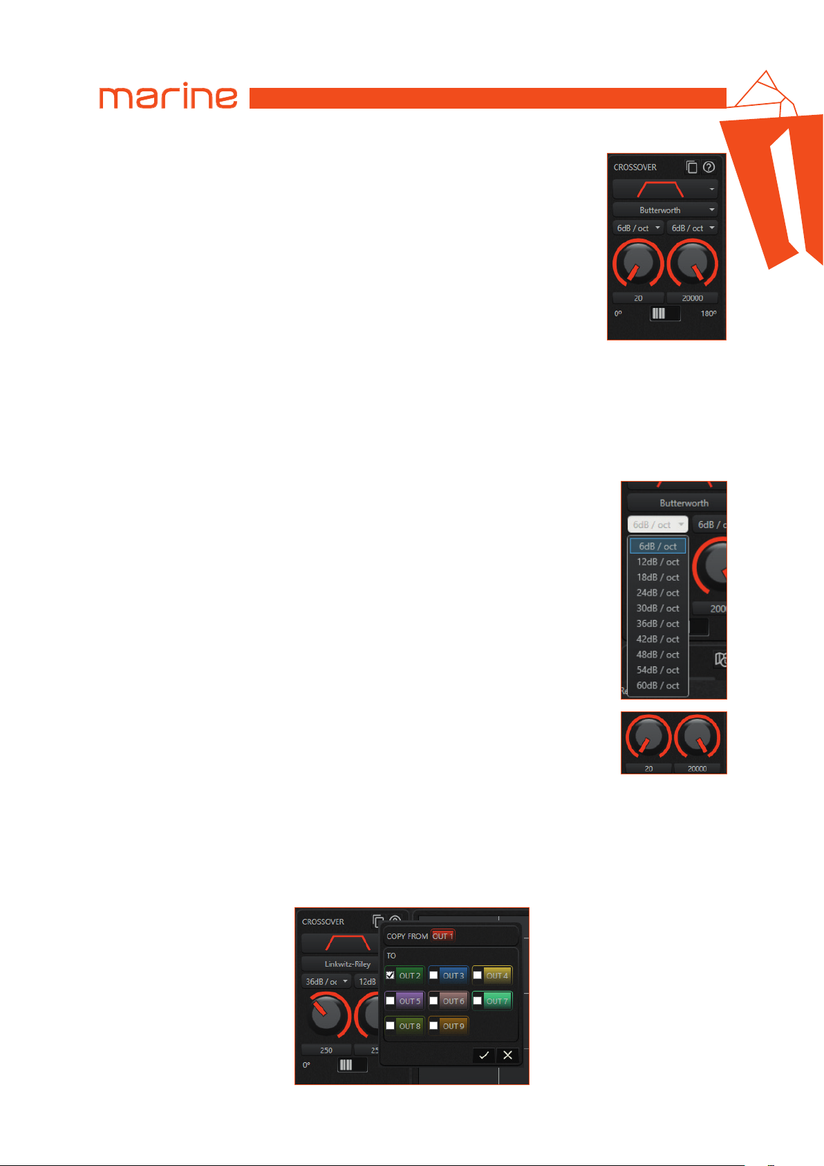
The Band Pass type is the combination of the previous two (high and low pass); it is
possible to select the name, slope and frequency for both filters.
•
NAME
After the type has been selected, the name filter option will display the following models:
1. Butterworth
2. LinkwitzRiley
3. Bessel
4. Chebyshev
5. QLP (quasi-linear phase)
•
SLOPE
When the name has been selected, the slope option will display the available slopes:
HMD8 DSP/
6
•
FREQUENCY
The last option to select is the cut-off frequency. It is possible to set it by using the knobs
or writing the frequency directly in the text box below the knobs.
Remark: all the frequencies are in hertz (Hz).
The minimum and maximum value for frequencies is 20Hz and 20000 Hz respectively.
Remark: if QLP has been selected, the knobs are disabled because the frequency values are discretized.
•
COPY PANEL
The image below shows the copy panel for the crossover: it is possible to copy all the parameters of the current
crossover to other output channels crossovers.
31
Page 32
USER’S MANUAL
6.4.10 EQUALIZER
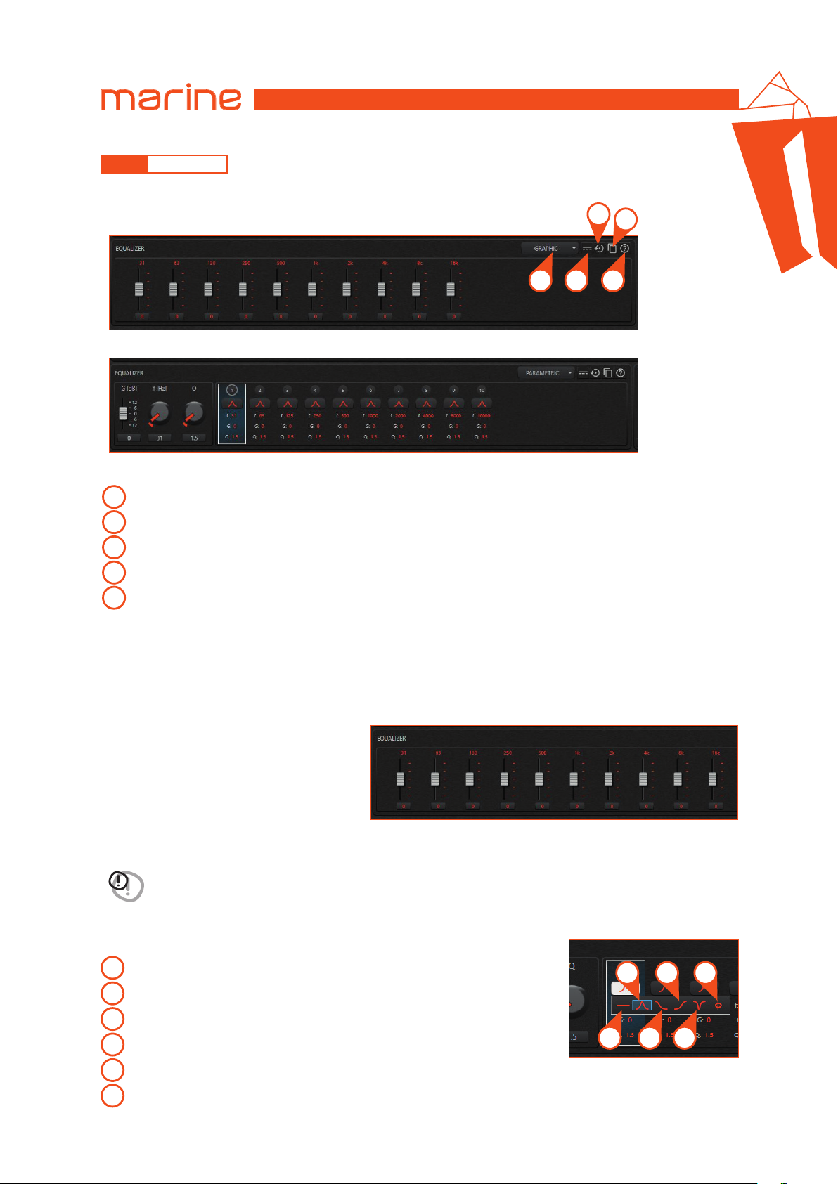
With the equalizer it is possible to emphasize or attenuate some frequencies rather than others.
The equalizer setting can be performed in two ways:
• Graphic equalizer
3
HMD8 DSP/
4
6
1 2 5
• Parametric equalizer
The following functions are available for both the graphic and parametric equalizers.
Equalizer type selection: allows you to select the equalizer type between graphic or parametric.
1
Bypass toggle button: allows you to bypass or not the equalizer filters.
2
Reset button: restore to default values all sections of current equalizer.
3
Copy panel: open the equalizer copy panel.
4
Help: to open the user guide.
5
Remark: all the frequencies are in hertz (Hz) and all the gains are in decibel (dB).
Remark: the output you are acting on is indicated by the foreground color of the equalizer panel.
Remark: the equalizer of each output channel is linked to the currently selected source. For each source it is necessary
to set the equalizers on the output channels.
•
GRAPHIC EQUALIZER
With the graphic equalizer it is possibile to set only the gain for every band, from -12 dB to +12 dB:
The central frequency of each band is indicated
above the slider and the gain can be set with the
slider or using the text box below the slider.
•
PARAMETRIC EQUALIZER
With the parametric equalizer it is possible to set more parameters than graphic equalizer for every section.
WARNING: the parameters of each section of the parametric equalizer are linked to each other. When a parameter is
changed, it may cause changes to other parameters. Be careful when changing the parameters.
By selecting the desired section it is possible to change the different parameters of this
section. The first parameter you can set is the type of section filter.
The available types are:
Flat
1
Peaking
2
Low shelving
3
High shelving
4
Notch
5
All-pass
6
32
2 4 6
1
3 5
Page 33
USER’S MANUAL
After selecting the filter type it is possible to set the Gain, Frequency and the Form factor (Q), except for Flat where it is
not possible to set any parameters.
The minimum and maximum Gain is -12 dB and +12 dB. For Notch or All-pass the gain is set to 0
dB and cannot be changed.
For Low shelving the minimum and maximum frequency is 20 Hz and 1000 Hz respectively; for
High shelving the minimum and maximum frequency is 8000 Hz and 20000 Hz respectively and for
all other filter types (except for Flat) the minimum and maximum frequency is 20 Hz and 20000 Hz.
The minimum and maximum value for Form factor (Q) is 0.5 and 16 for Peaking and All-pass types.
For the shelving types (low and high) the minimum and maximum value for Q is 0.5 and 1.41.
Finally, for the Notch type, the minimum and maximum value for Q is 1.44 and 16.
HMD8 DSP/
6
WARNING: when changing from the parametric type to the graphic type, some set parameters can be modified
according to the constraints imposed by the graphic equalizer (filter type, frequency, form factor (Q), ...).
•
COPY PANEL
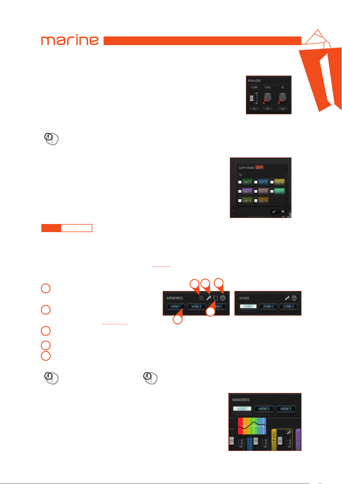
The image on the side shows the copy panel for the equalizer: it is possible to
copy all the sections of the current equalizer to other output channels equalizers.
6.4.11 MEMORIES
With memories it is possible to characterize the sound using a frequency filtering similar to the one of the equalizer.
Remark: you can activate only one memory at a time or deactivate it through the memory panel of the configuration
software when the amplifier is connected to the PC.
When the configuration of the device is completed and it is disconnected from the PC, the memories are selected
with the appropriate Memory selection switch
The images below describe the memories panel and the functions available when a memory is selected.
Selection toggle button: to select and then activate
1
the memory. It also activates the Advanced
settings button.
Advanced settings panel: to open the advanced
2
settings panel of the selected memory.
See Memory equalizer
Memories settings panel: to open the memories
3
settings panel.
Copy panel: to open the memories copy panel.
4
Help: to open the user guide.
5
(see sec. 6.4.11.1)
.
WARNING: each memory acts on
all outputs!
When you hover the mouse over a memory button, the memories panel provides a
preview of the filtering curve with a tooltip, like in the image below.
(see sec. 5.2)
.
5
3
2
4
1
WARNING: when a memory is deactivated all its customizations
are deactivated!
33
Page 34
USER’S MANUAL
•
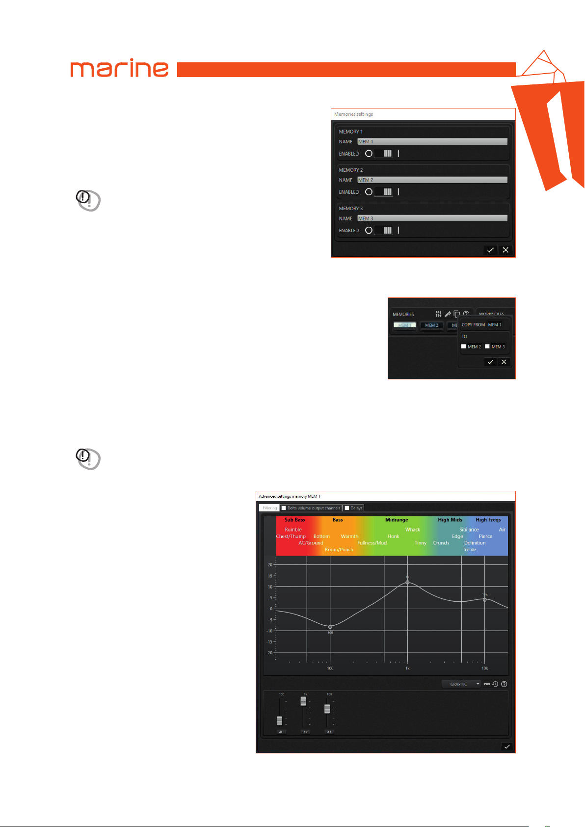
MEMORIES SETTINGS PANEL
The image on the side shows the settings panel for the memories.
The memories can be:
• renamed;
• disabled / enabled.
WARNING: when a memory is disabled it is definitively unusable.
It is not possible to rename or customize it.
•
COPY PANEL
This feature allows you to copy the advanced settings of the active memory
to other memories.
HMD8 DSP/
6
6.4.11.1 MEMORY EQUALIZER
Advanced memory settings include an equalizer that allows you to perform an additional equalization.
WARNING: the filters of this equalizer are applied to all the output channels when the memory is selected.
The equalizer setting can be performed in two ways:
•
GRAPHIC EQUALIZER
34
Page 35
•
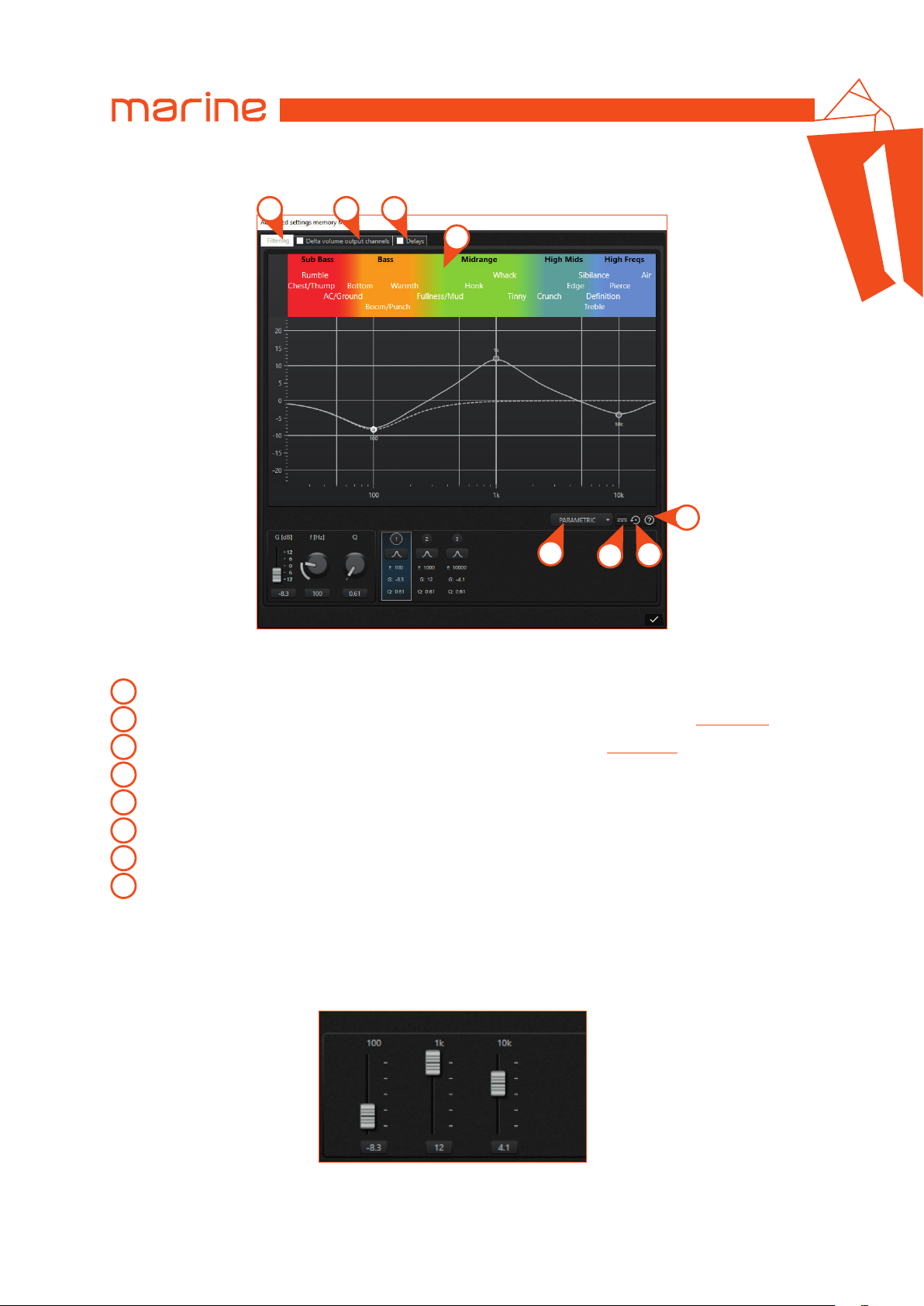
PARAMETRIC EQUALIZER
USER’S MANUAL
1 2 3
HMD8 DSP/
6
4
8
5
The following functions are available for both the graphic and parametric equalizers.
Equalizer panel: allows you to select the memory equalizer filter panel.
1
Delta volume panel: allows you to select the memory delta volume panel. See Memory volume
2
Delays panel: allows you to select the memory delays panel. See Memory delay
3
Sound sensations band: provides a subjective description of the sound frequencies.
4
Equalizer type selection: allows you to select the equalizer type between graphic or parametric.
5
Bypass toggle button: allows you to bypass or not the equalizer filters.
6
Reset button: restore to default values all sections of current equalizer.
7
Help: to open the user guide.
8
Remark: all the frequencies are in hertz (Hz) and all the gains are in decibel (dB).
•
GRAPHIC EQUALIZER
With the graphic equalizer it is possible to set only the gain for every band, from -12 dB to +12 dB:
7
6
(see sec. 6.4.11.3)
.
(see sec. 6.4.11.2).
The central frequency of each band is indicated above the slider and the gain can be set with the slider or using text
box below the slider.
35
Page 36
USER’S MANUAL
•
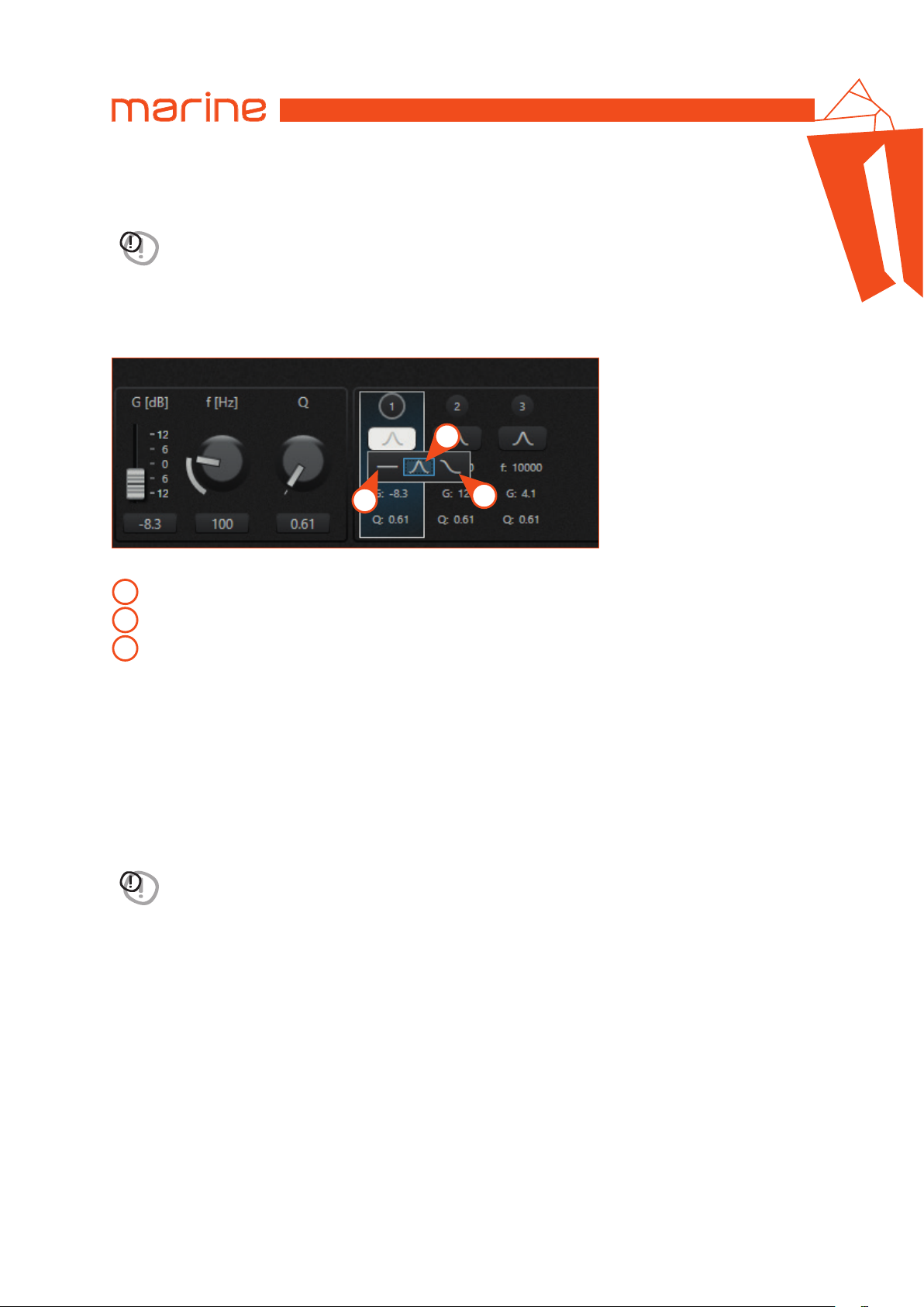
PARAMETRIC EQUALIZER
With the parametric equalizer it is possible to set more parameters for every section than the graphic equalizer.
HMD8 DSP/
6
WARNING: the parameters of each section of the parametric equalizer are linked to each other. When a parameter is
changed, it may cause changes to other parameters. Be careful when changing the parameters
Remark: when the equalizer is in parametric mode, the frequency response of the single section currently selected is
shown on the graph with a white dotted line.
By selecting the desired section it is possible to change the different parameters of this section. The first parameter
you can set is the type of section filter.
2
1
The types available are:
Flat
1
Peaking
2
Low / High shelving
3
Remark: not all sections have all types of filters available.
After selecting the filter type it is possible to set the Gain, Frequency and the Form factor (Q), except for Flat where it
is not possible to set any parameters.
The minimum and maximum Gain is -12 dB and +12 dB.
For Low shelving the minimum and maximum frequency is 20 Hz and 1000 Hz respectively; for High shelving the
minimum and maximum frequency is 8000 Hz and 20000 Hz respectively; for Peaking the minimum and maximum
frequency is 20 Hz and 20000 Hz.
The minimum and maximum value for the Peaking Form factor (Q) is 0.5 and 16; for shelving types (low and high) the
Form factor (Q) ranges from 0.5 to 1.41.
3
WARNING: when changing from the parametric type to the graphic type, some set parameters can be modified
according to the constraints imposed by the graphic equalizer (filter type, frequency, form factor (Q), ...).
36
Page 37
USER’S MANUAL
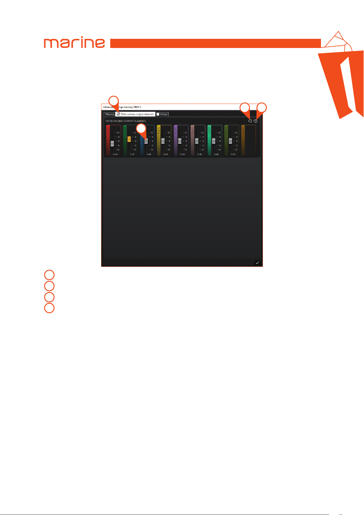
6.4.11.2 MEMORY VOLUME
The selected memory allows this further customization for the output channels volumes.
Remark: this function is applied to the output channels only when the memory is selected.
1
3 4
2
HMD8 DSP/
6
Delta volume checkbox: allows you to enable or disable this additional feature of the selected memory.
1
Delta volume level: adjusts the delta volume related to the output channel level.
2
Reset button: restore all sliders to 0 dB.
3
4
Help: to open the user guide.
Remark: this function is enabled only if a check mark is placed in the related check box on the top tab!
Delta volume is an adjustment of the output channels level ranging from -12 dB to +12 dB: these corrections are
added to the volumes set in the main output channels panel.
When the delta volume brings the output channel volume beyond the limits (above 0 dB or below -40 dB) the slider
turns orange: in these cases, the maximum (0 dB) or minimum (-40 dB) value is assigned to the output channel.
37
Page 38
USER’S MANUAL
6.4.11.3 MEMORY DELAY
The selected memory allows this further customization for the output channels delays.
Remark: this function is applied to the output channels only when the memory is selected.
HMD8 DSP/
6
4
5
1
2
3
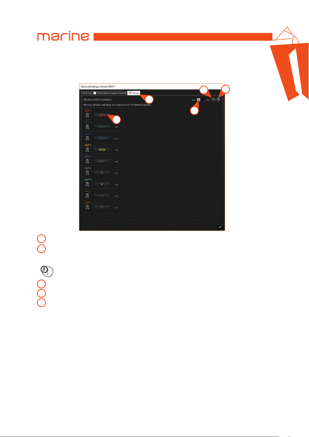
1
Delays checkbox: allows you to enable or disable this additional feature of the selected memory.
Delays unit of measurement: it allows you to set the unit of measurement of delays by choosing between
2
distance (cm) or time (ms).
WARNING: for each output channel, both the distance and the delay are measured with respect to the most
distant speaker.
Delay text box: it allows you to enter the distance or delay based on the unit of measurement selected.
3
Reset button: restore all the delays of the selected memory to 0 ms.
4
Help: to open the user guide.
5
Remark: this function is enabled only if a check mark is placed in the related check box on the top tab!
The memory delays function provides the ability to enter the delay value in milliseconds for each output channel:
these delays replace those set in the delay panel or those calculated by the automatic delay calculation command
(according to the speakers position).
When the memory is deselected (or the memory delay function is disabled by removing the check mark), the delays
are restored to the original values set for each output channel.
38
Page 39
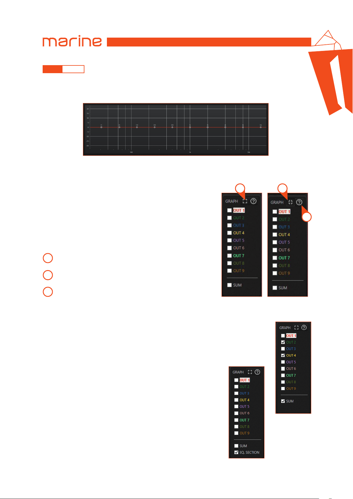
USER’S MANUAL
HMD8 DSP/
6
6.4.12 GRAPH
1 GRAPH
The Graph displays the frequency response of the output channels. On the x-axis there is the frequency in hertz (Hz),
represented with a logarithmic scale; on the y-axis the amplitude of the signal is represented in decibels (dB).
2 GRAPH SETTINGS
The image below shows the graph settings panel to select what to observe on the graph.
1 2
3
Expand graph: allows you to enlarge the size of the graph, reducing the
1
output channel settings panel. When clicked, its appearance changes.
Restore graph: allows you to restore the original size of the graph.
2
More details in the next paragraph.
Help: to open the user guide.
3
The frequency response of the currently selected output channel, identified by the white background around the name,
is always shown on the graph.
By selecting the check boxes it is possible to simultaneously display more output channels frequency
responses on the graph. Furthermore, if the sum box is checked, the sum of the frequency responses
of the currently checked channels is shown on the graph.
If the parametric equalizer is used, the EQ. SECTION item appears at the bottom
of the graph settings panel: putting the check mark on it, a dashed line that
represents the frequency response of the equalizer selected section, is shown
on the graph.
Remark: only the output channels belonging to the currently selected zone are listed on the graph settings panel.
39
Page 40
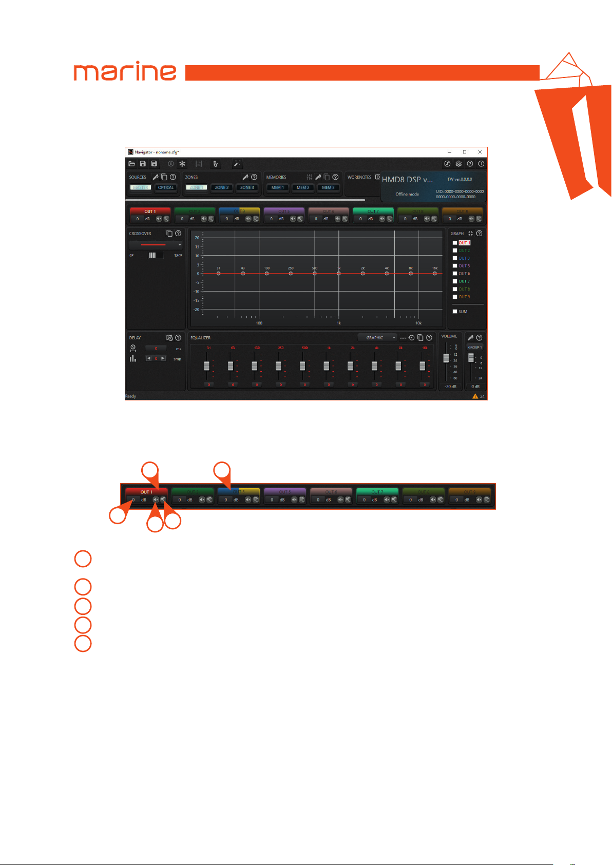
USER’S MANUAL
3 GRAPH RESIZE
When the graph resize button is clicked, the graphic layout adopted by the software is shown in the image below.
HMD8 DSP/
6
As you can see, the input channels panel and the zone volume panel are hidden, while the output channels panel
takes on a reduced graphic layout.
The image below shows an overview of the functions available on the output channel settings panel in this reduced mode:
1 5
2
Selection button: the output channel is selected by clicking on its name. The currently selected channel has the
1
name highlighted in white.
Channel level: allows you to enter the channel level.
2
Mute: allows you to mute the channel (mute).
3
Solo: allows you to listen to the channel silencing all the others (solo).
4
Bridged channels appearance: when a channel is set to bridge mode, it is represented in this way.
5
4
3
40
Page 41
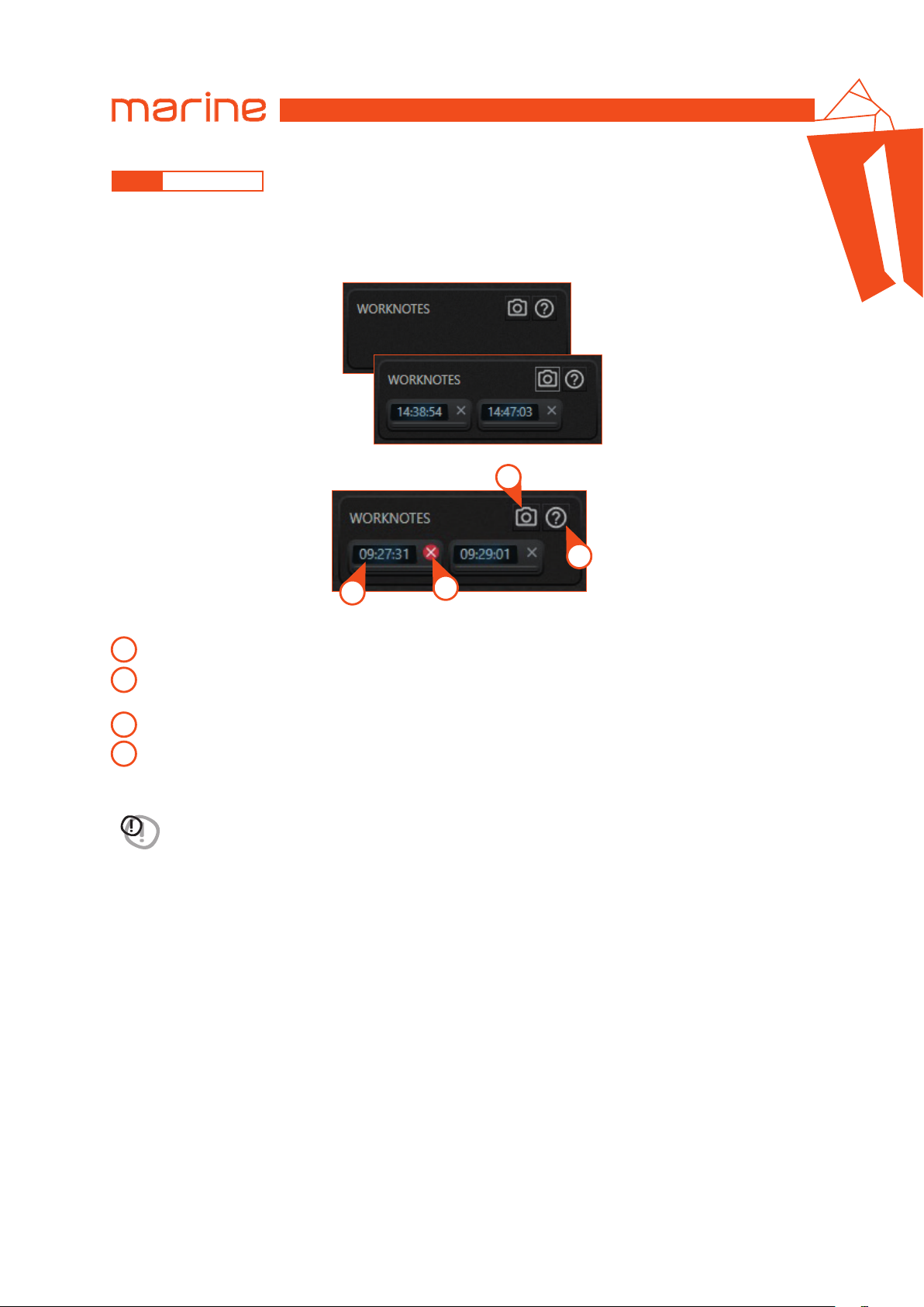
USER’S MANUAL
6.4.13 WORK NOTES
The Work Notes panel allows you to capture a snapshot of the whole current configuration. This function makes a
copy of the current configuration to the clipboard.
The images below show the Work Notes panel both when it is empty and when it contains snapshots.
HMD8 DSP/
1
4
6
2
1
Camera button: allows you to take a snapshot of the current configuration.
Snapshot load button: allows you to reload the configuration of that snapshot. Each button shows the snapshot
2
capture time as identification.
Snapshot delete button: allows you to permanently delete a snapshot.
3
Help: to open the user guide.
4
Remark: there is no limit to the number of snapshots that can be captured.
WARNING: snapshots are volatile and are not saved on the computer: they are only work notes!
When the software is closed, all snapshots are lost.
Remark: if you want to save a configuration contained in a snapshot, you must first reload the configuration by
clicking on the snapshot load button and then use the SAVE AS command located in the top command bar.
3
41
Page 42
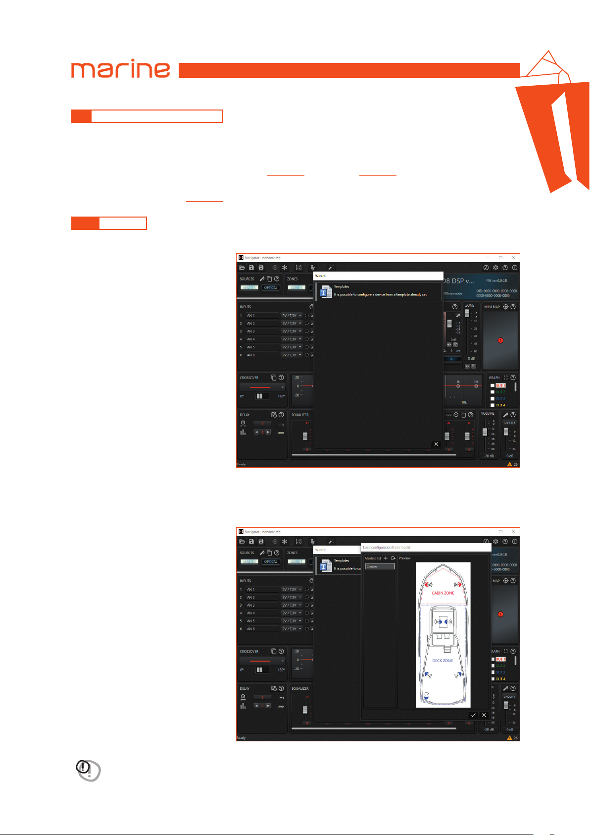
USER’S MANUAL
HMD8 DSP/
6
6.5 EXTENDED FUNCTIONALITIES
The software dynamically reshapes depending on the device to which it connects.
During synchronization, the device communicates the current configuration but also the details inherent to the
functionalities it implements.
These functionalities are divided between Wizards
(see sec. 6.5.1)
and Features
(see sec. 6.5.2)
.
The software provides an additional functionality which is independent of the connected device.
This is the Real time analysis
(see sec. 6.5.3)
.
6.5.1 WIZARDS
Within this definition are grouped all the automatic procedures that facilitate the user during the audio setup process.
Ultimately, these are procedural
abstractions whose purpose is to
create a device configuration (or part
of it), rationalizing the steps according
to a simpler and more intuitive visual
interface for the user.
6.5.1.1 LOAD CONFIGURATION FROM A TEMPLATE
This automatic procedure simply allows you to load a configuration from one of the models that the software makes available.
WARNING: before loading the template make sure that all the connections have been performed correctly.
It is strongly advised to maintain a low volume of the system to avoid possible damage to the loudspeakers in
the event of an error in the connections.
42
Page 43
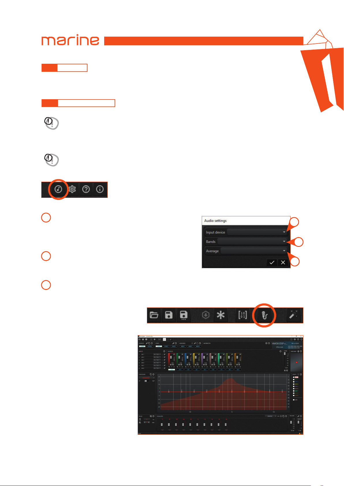
USER’S MANUAL
HMD8 DSP/
6.5.2 FEATURES
Within this group are instead all the extensions that can be activated or deactivated by the user during system operation.
Remark: HMD8 DSP does not implement any features.
6.5.3 REAL TIME ANALYSIS
WARNING: the Real time analysis functionality (RTA) is not a measuring instrument! It is an aid for setting up the
audio system.
The Real time analysis allows you to observe the frequency spectrum of an audio signal on the graph. It works in real time
and needs a microphone connected to the PC to detect the audio signal.
WARNING: before using the RTA function, you must select the audio input device connected to the PC.
To access the audio settings panel, there is a button on the right side toolbar:
The images below show the audio settings panel.
6
1
Input device: allows you to select the audio input device
connected to the PC.
Remark: it is highly recommended to use a good quality
microphone that has a USB connector, and not the integrated
microphone of the PC.
Bands: allows you to choose the number of audio spectrum
2
frequency bands between octave (10 frequency bands),
3rd octave (30 frequency bands), 6th octave (60 frequency bands),
12th octave (120 frequency bands).
Average: allows you to choose the time window length in which the average is calculated
3
(short; normal; long). This setting modifies the responsiveness of the bar graph.
Finally, to activate or deactivate the real
time analysis, there is a toggle button on
the top command bar:
The frequency spectrum of the detected
audio signal will appear in the graph
background. The decibel scale related to
the amplitude of the RTA is shown on
the right side of the graph.
1
2
3
Remark: when the RTA function is activated, the audio settings icon is disabled. To change the audio settings it is
necessary to turn the RTA off.
43
Page 44
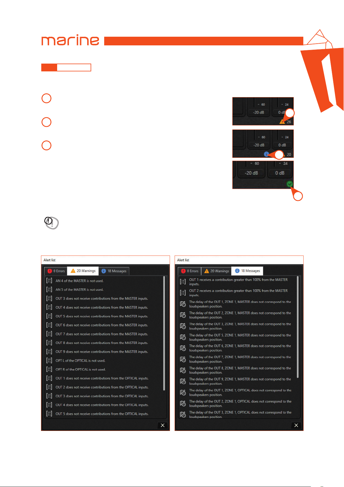
USER’S MANUAL
6.5.4 STATUS BAR
The status bar is located at the bottom of the configuration software and provides some useful information for the user.
In particular, some icons are shown on the right side of the status bar as in the following images:
1
Warning: indicates the presence of potential configuration problems. This
type of warning occurs when, in the mixer, one or more inputs of a source are
not used, or an output channel does not receive any signal contribution.
Info: provides useful information. These types of information occur when an
2
output channel receives a total contribution greater than 100% in the mixer,
or the delays of the output channels do not match the position of the speakers.
OK: indicates that no potential configuration problems are detected.
3
HMD8 DSP/
1
2
6
The number next to each symbol indicates the amount of warnings or information.
WARNING: all these messages are a reminder and can indicate a possible forgetfulness by the user. It is not necessary
to fix all the warnings and infos to save the configuration on the PC or finalize the connected device, as long as
the user is aware of it.
By clicking on the symbols an alert list panel opens that allows you to view the attached messages. The image below shows
the alert list panel containing some sample messages.
3
44
Page 45
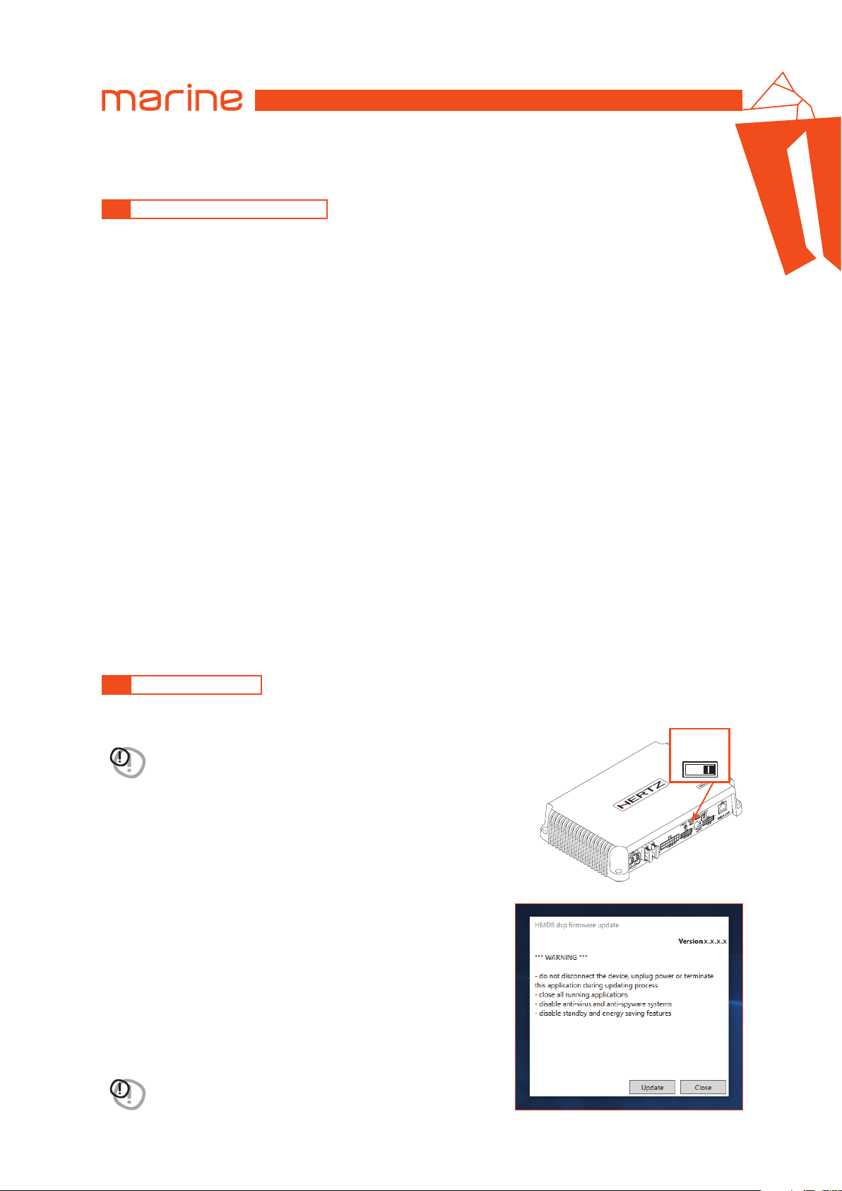
USER’S MANUAL
USB
OPTICAL SEL.
UPGRADEPRESETS
OPTICAL IN
DRC
REM IN
HMD8 DSP/
7
7. TROUBLESHOOTING
7.1 SYNCHRONIZATION WITH A PC
1. HMD8 DSP operating problems
If, when calibrating the system with HMD8 DSP connected to a laptop there are operating problems, try
disconnecting the laptop power supply cable.
With the laptop working on battery power you avoid a possible voltage difference in the USB ground between
the vehicle (HMD8 DSP) and the ground (PC).
2. Connection lost between HMD8 DSP and the PC
If, while calibrating the system with the PC connected to HMD8 DSP, the amplifier is turned off and back on again,
the connection is lost and the software cannot finalize the adjustments that were set. To avoid losing the
settings, proceed as follows:
a. Save the setup to a file on the PC using the Save or Save As function.
b. Exit the software.
c. Turn HMD8 DSP on.
d. Launch the software again.
e. Load the setup file again that was saved using the Open function.
3. HMD8 DSP does not respond
If while calibrating the system with the PC connected to HMD8 DSP the latter does not respond to the commands,
proceed as follows:
a. Turn off HMD8 DSP by disconnecting the Remote IN or even disconnecting the power cable for a second.
b. Save the setup to a file on the PC using the Save or Save As function.
c. Exit the software.
d. Turn HMD8 DSP on.
e. Launch the software again.
f. Load the setup file again that was saved using the Open function.
4. Settings not saved
To successfully complete HMD8 DSP configuration and not lose the work done, remember to store the settings
that were made. From the management software menu select “Finalize”.
7.2 FIRMWARE UPDATE
The device firmware can be updated using a specific application. Make sure the device is turned on and connected to the PC.
WARNING:
move the upgrade switch to the ON position before supplying power. The logo will start
if you are restoring the device from an error state and it doesn’t normally turn on,
OFF ON
flashing and you will be ready to start the update.
Run the application and follow the instructions.
WARNING: do not disconnect or power down the device until the
procedure has been completed.
45
Page 46
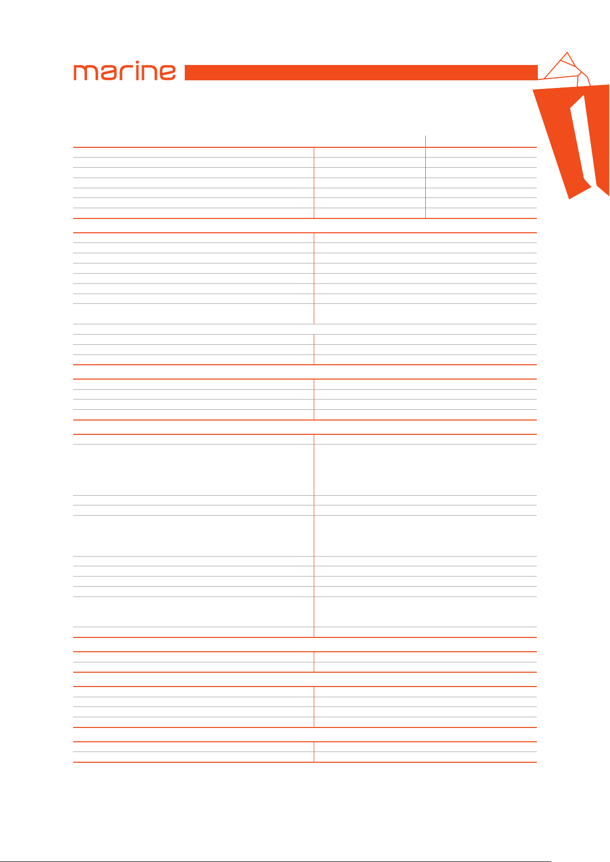
USER’S MANUAL
HMD8 DSP/
8. TECHNICAL SPECIFICATIONS
POWER SUPPLY HMD8 DSP 12 V HMD8 DSP 24 V
Power supply voltage / fuse: 11 ÷ 15 VDC / 2 x 30 A 22 ÷ 34 VDC / 2 x 15 A
Operating power supply voltage: 6.5 V ÷ 17 V 14 V ÷ 36 V
Idling current: 1.6 A 0.96 A
Switched off consumption: 1.7 mA 1.6 mA
Consumption @ 14.4 VDC, 2Ω, Max Musical Power: 55 A 27.5 A
Remote IN: 6 ÷ 15 VDC (1 mA) 6 ÷ 34 VDC (1 mA)
Remote OUT: 4 ÷ 15 VDC (150 mA) 14 ÷ 34 VDC (150 mA)
AMPLIFIER STAGE HMD8 DSP 12 V / 24 V
Distortion - THD @ 1 kHz, 4Ω, 70% Rated Power: 0.06 %
Damping factor @ 1 kHz, 4Ω, 2 VRMS: > 110
Bandwidth @ -1.5 dB: 10Hz ÷ 22 kHz
S/N ratio (A weighted @ 1 V Input) Master Input: 100 dBA
S/N ratio (A weighted @ 1 V Input) Optical Input: 105 dBA
Input sensitivity Pre-In: 0.6 ÷ 6 VRMS
Input sensitivity Speaker-In: 2.2 ÷ 22 VRMS
Minimum load impedance:
Output power (RMS) @14.4 VDC, 1% THD (HMD8 DSP); @28.8 VDC, 1% THD (HMD8 DSP 24V):
• 8 Ch @ 4Ω: 85 W x 8
• 8 Ch @ 2Ω: 130 W x 8
• 4Ch (Bridge 1/2; 3/4; 5/6; 7/8) @ 4Ω: 260 W x 4
4Ch - (Bridge 1/2; 3/4; 5/6; 7/8): 4Ω
INPUTS / OUTPUTS HMD8 DSP 12 V / 24 V
Pre-In Inputs: Ch1 ÷ Ch6 customizzabile
Speaker-In Inputs: Ch1 ÷ Ch6 customizzabile
Digital IN: 1 x Optical S/PDIF; Max 192 kHz / 24 bit
Sub Out (RCA Pre Out): 4 VRMS Max
DIGITAL SIGNAL PROCESSOR HMD8 DSP 12 V / 24 V
Filter type: Full / Hi pass / Low Pass / Band Pass
Butterwor th (6, 12, 18, 24, 30, 3 6, 42, 4 8, 54, 60 dB/oct)
Filter mode and slope:
Crossover frequency: 20 ÷ 20k Hz
Phase control: 0° / 180°
Output Equalizer:
Time Alignment Distance: 0 ÷ 510 cm / 0 ÷ 200.8 inches
Time Alignment Delay: 0 ÷ 15 ms
Time Alignment Step: 1 cm
Time Alignment Fine SET: 1 sample
Memories:
Preset (Drive Preset): Rotary switch for 7 installation Presets
Chebyshev (6, 12, 18, 24, 3 0, 36, 42, 48, 54, 60 dB/oct)
n. 10 parametric poles (Peaking, High Shelf, Low Shelf,
n. 3 parametric poles for each memory (Peaking, High
Shelf, Low Shelf) ±12 dB gain, variable Q (0.5 – 16.0)
Linkwitz-Riley (12, 24, 36, 4 8, 60 dB/oct)
Bessel (6, 12, 18, 24, 30, 36, 42, 48 , 54, 60 dB/oct)
QLP quasi-linear phase (6, 12 dB/oct)
Graphic and Parametric modes
Notch, All pass) ±12 dB gain, variable Q (0.5 – 16.0)
n. 10 graphic poles
CONTROL CONNECTIONS HMD8 DSP 12 V / 24 V
From / to personal computer: 1 x micro USB-B
Memory selection: CTRL 1 / CTRL 2
GENERAL REQUIREMENTS HMD8 DSP 12 V / 24 V
PC connections: Micro USB 1.1 / 2.0 / 3.0 Compatible
Software/ PC requirements: Microsoft Windows (32/64 bit): Win 7, Win 8, Win 10
Video resolution with screen resize: min. 1024 x 600
Ambient operating temperature range: 0 °C to 55 °C (32 °F to 131 °F)
SIZE / WEIGHT HMD8 DSP 12 V / 24 V
Max size W x H x D (mm/inch): 243 x 48 x 159 / 9.56 x 1.89 x 6.2
Weight (kg/lb): 2 / 4.4
8Ch: 2Ω
n. 3 memories
8
46
Page 47
All specifications subject to change without notice
PART OF ELETTROMEDIA - 62018 Potenza Picena (MC) Italy - T +39 0733 870 870 - F +39 0733 870 880 - www.elettromedia.it
 Loading...