

Page 1

USER MANUAL FOR CO2 ABSORBER
CIRCUIT
KAV-1
Puerto de Navacerrada 3, P.I. Las Nieves
28935 Móstoles - España
Tlfo.: 91 616 4642 - Fax: 91 616 4892
Manual Ref.: 9130001
Edition: 2002
Revision: 3
0 3 1 8
Page 2

KAV-1
INSTRUCTION MANUAL
CO2 absorber
INTRODUCTION
The circular circuit is a respiration system that contains one-way inspiration and expiration
circuits, together with a CO2 absorbing device.
COMPONENTS OF A CIRCULAR SYSTEM
The basic components of a circular system are:
- A common fresh gas intake.
- One inspiratory branch and one expiratory branch, each one equipped with a one-way
valve.
- A spontaneous / manual ventilation circuit, including a reservoir bag.
- A mechanical ventilation circuit, including a concertina or bellows.
-A CO2 absorption system (canister).
- An APL or overpressure valve for manual ventilation, a pressure-limiting valve for
mechanical ventilation and a residual gas exhaust conduit.
HERSILL KAV-I ABSORBER DEVICE
The new KAV-1 CO2 absorber is made of stainless steel, brass, polysulfone and silicon,
making it the ideal choice for:
- Surgery in the operating theatres of hospitals and public health clinics.
- Veterinary and dental surgery.
- Emergencies, ambulances and military uses.
All the device’s components have been designed and manufactured to optimise its use. For
example, the apparatus has a smaller-than-usual canister because experience has shown that
large tanks of soda lime are harder to handle.
The CO2 absorption capacity can easily be doubled or trebled by placing one canister on top
of another.
Page 3

The circuit can be used both for high and low flow techniques:
1. High flows: Using fresh gas flows near the patient’s normal ventilation. In this case the
circular system behaves as a partial reinhalation/non-reinhalation system, increasing the
effective life of the soda lime with higher fresh gas flows.
2. Low flows (1 - 1.5 l/min) or minimum flows (0.5 - 1 l/min) of fresh gases for the patient’s
ventilation. Using this circular circuit with low flows permits the following:
a) High use of fresh gases;
b) Minimum possibilities of leaks;
c) Efficient use of the soda lime;
d) Minimum risk of disconnection;
e) Only the inhaled gas passes through the soda lime;
f) It improves heat and humidity retention;
g) Economic benefit, reducing the annual costs of volatile anaesthetic agents;
h) Reduction in amount of nitrous oxide (N2O) released to the atmosphere, where it
causes a greenhouse effect, and of other inhalatory agents.
To change the nature of the circuit from reinhalation to non-reinhalation, or vice-versa, you
only have to change the flow of fresh gases, and there are no switches.
When the circuit is adapted to our REX and REGINA anaesthesia machines, and to our ORBI
portable anaesthesia device, with all the monitoring devices, it can be used for the following
purposes:
a.- For monitoring of essential ventilation parameters.
b.- For extensive monitoring of respiratory gases.
It can be also used with the following devices:
c.- A respirator with an ascending concertina.
d.- A vaporiser suitable for operating with low flows.
e.- High-precision variable area flowmeters equipped with an antihipoxia system.
The appropriate position of the expiratory valve in the system, and the
carefully studied position of the fresh gas supply, make the KAV-1 the
IDEAL CIRCUIT FOR USE WITH LOW FLOWS
Page 4

INSTRUCTIONS FOR USE
1. Respiratory Circuit.
Visually inspect all the components.
Check that the inspiratory and expiratory valves work properly.
Replace any faulty parts.
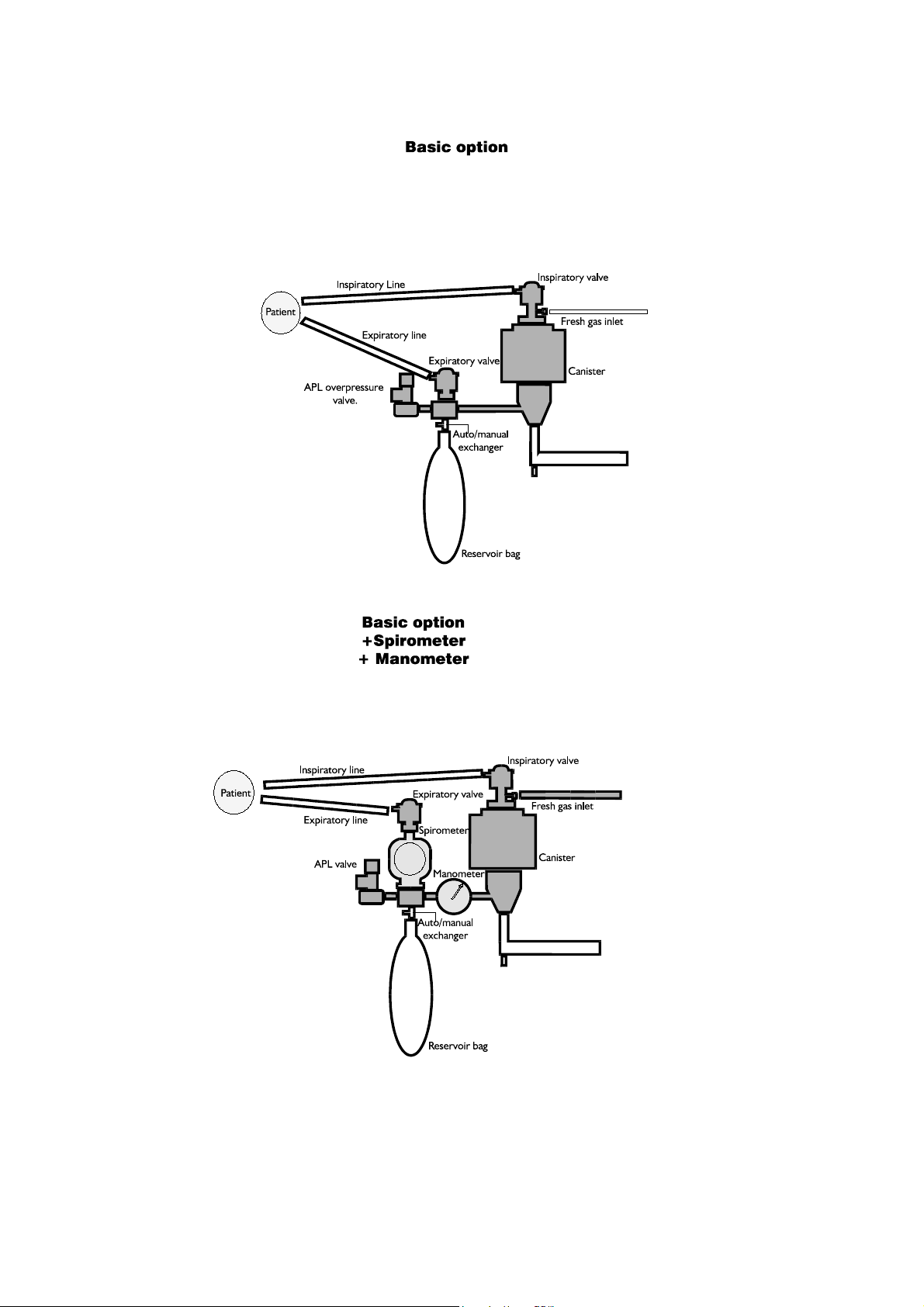
For instructions on how to assemble the circuit, please turn to the annexes:
- Assembly of the absorber circuit - Basic option
- Assembly of the absorber circuit - Basic option + expirometer + manometer
2. Canister
Check the state of use of the soda lime. Please note the absorbent change date, because
an absorbent that has remained in a canister too long and become unusable may not have
changed colour, without having reversed.
Calculate the duration of the operation in relation to the state of the absorbent and its
location (inspiratory or expiratory branch) so that it does not have to be changed while
the patient is being anaesthetised.
Before each operation, pass flows of 100% O2 through the lime deposit to remove any
residual gases that may have accumulated during previous operations.
Disconnect the canister from the circuit before filling it with soda lime. Pour the soda
lime granules into the canister, turning it to ensure it fills smoothly (without pressing it).
Put the canister back in the circuit.
PRECAUTIONS
- The canister must only be used in the upright position.
- It must not be used near inflammable anaesthesia.
- The accumulated condensation at the bottom of the canister is caustic, so be very careful
and make sure that it does touch your skin when draining you are draining the canister.
- If the ventilator is not connected, keep the manual/automatic switch in the manual position
to avoid gas leaks.
- A lack of absorbent may cause inefficient CO2 absorption, whereas an excess may cause
inefficient sealing.
- Make sure to check to respirator (see equipment manual) before you use the circular
circuit and the canister.
Page 5

- After cleaning the circuit, check that the inspiratory and expiratory valves work properly. If
they do not, make sure that they are dried and fitted correctly.
- Make sure that the fresh gas intake tube is not crushed or folded, because otherwise an
anaesthetic accident may occur.
- DO NOT use vacuum system connected directly to the APL valve; place a collector
system with a positive and negative pressure control in between the vacuum system and
APL valve.
LEAKS
1. Patient’s Circuit
In order to detect leaks in the patient’s circuit, connect the fresh gas outlet to the outlet
of the patient’s circuit. Select manual ventilation and close the APL valve. Close the
variable air flowmeters. Block the circuit terminal (patient connector). Press the
emergency O2 button until a pressure of + 30 cm H2O has been reached, and check that
the circuit pressure manometer does not drop below this value.
If no air circuit pressure manometer has been installed, leave the bag where it is and fill it
to the top. Shut off the gas and check that the bag takes more than one minute to deflate.
2. Apl Valve and Exhaust Valve
After performing the previous checks, and with the patient connector still blocked, open
the APL valve gently and check that the gas escapes freely into the atmosphere. Apply
the maximum flow and check that the pressure is below 5 cm H2O.
Close the APL valve tightly. Keep the patient and bag connections blocked. Press the
emergency O
button and check that the pressure rises to 60 cm H2O. Replace the bag.
2
3. Inspiration and Expiration Valves
Disconnect the patient’s circuit. Close the APL valve. Block the inspiratory valve outlet
and Inflate the bag with a flow of approximately 2 l/min. Shut off the gas and check that
the bag does not empty through the expiratory valve.
Place another bag at the inspiratory valve outlet. Apply approximately 2 l/min of O
it. Shut off the gas. Check that the gas does not move flow back inside when you press
the additional bag gently.
Remove the additional bag and reinstall the circuit. Open the APL valve.
to fill
2
Page 6

4. Manual/Automatic Selector
Turn the selector to the “manual” position. Install a test bag on the Y-shaped connector.
Close the APL valve. Inflate the system with 2 l/min. Move the selector to the
“automatic” position and check that the system empties through the ventilator
connection gate. Select manual. Reinstall the system, checking the bags inflate and open
the APL valve to check that the system empties through it.
CLEANING AND DESINFECTION.
Any parts that are removed from the circuit (except for the pressure manometer and
Expirometer) must be cleaned in soapy water before being decontaminated or sterilised. The
parts must be sterilised for 30-45 minutes at 120º-130º in an autoclave.
1. Canister
These components MUST be cleaned. The soda lime tends to stick to surfaces when it
has been used. To ensure the canister is sealed properly, brush the seals and canister
under running water to remove all the soda lime particles, whenever you change the
lime.
To drain off the humidity, connect the tube to the drain outlet and put the other end in
an appropriate recipient.
N.B.: The accumulated condensation at the bottom of the canister is caustic. Make sure
that it does touch your skin. The canister must be dried thoroughly after it has been
drained.
2. Inspiration / Expiration Valves
Open the valves and rinse the disks and tops with water. Dry them very carefully. The
disks MUST NOT be bent, because otherwise the system will not pass the operating
tests.
The pressure manometer and expirometer must be sterilised in ethylene oxide.
Page 7
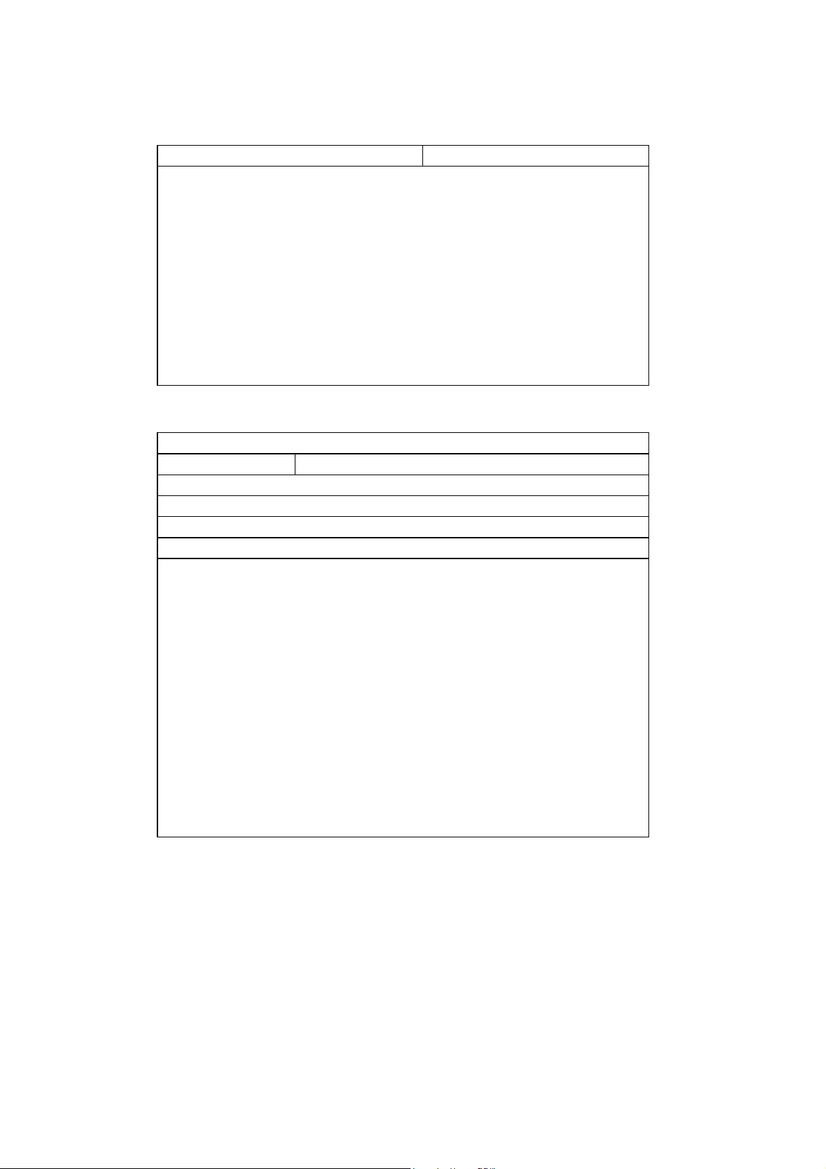
ORDER REFERENCE NUMBERS
CODE DESCRIPTION
5130000 CO2 ABSORBER
Basic components:
4130001 Expiratory valve
4130002 Inspiratory valve
5130010 Canister
0150013 APL valve
0170004 Gas connector
0140115 1 metre anaesthesia tube
OPTIONAL
CODE DESCRIPTION
4130003 Manual / Automatic Selector
0120005 Wright MK-8 Expirometer
3190300 -20 to 100 cmH2O pressure manometer
0530003 MINIOX III O2 monitor
5115500 Patient’s circuit
Components:
0170001 Male tube mount
0170002 Female tube mount
0140113 22 mm 106 cm ringed tube
0170007 Y-shaped connector
0170005 Intubation connector
0142004 2 litre reinspiration bag
0170006 Mask connector
014000x Anaesthesia mask
0140101 14 mm 9 cm fine ringed tube (3 units)
Page 8

ANNEXES
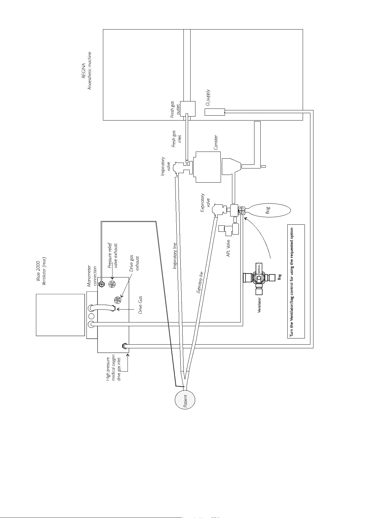
ASSEMBLY OF THE ABSORBER CIRCUIT
Basic Option
Basic Option + Expirometer + Manometer
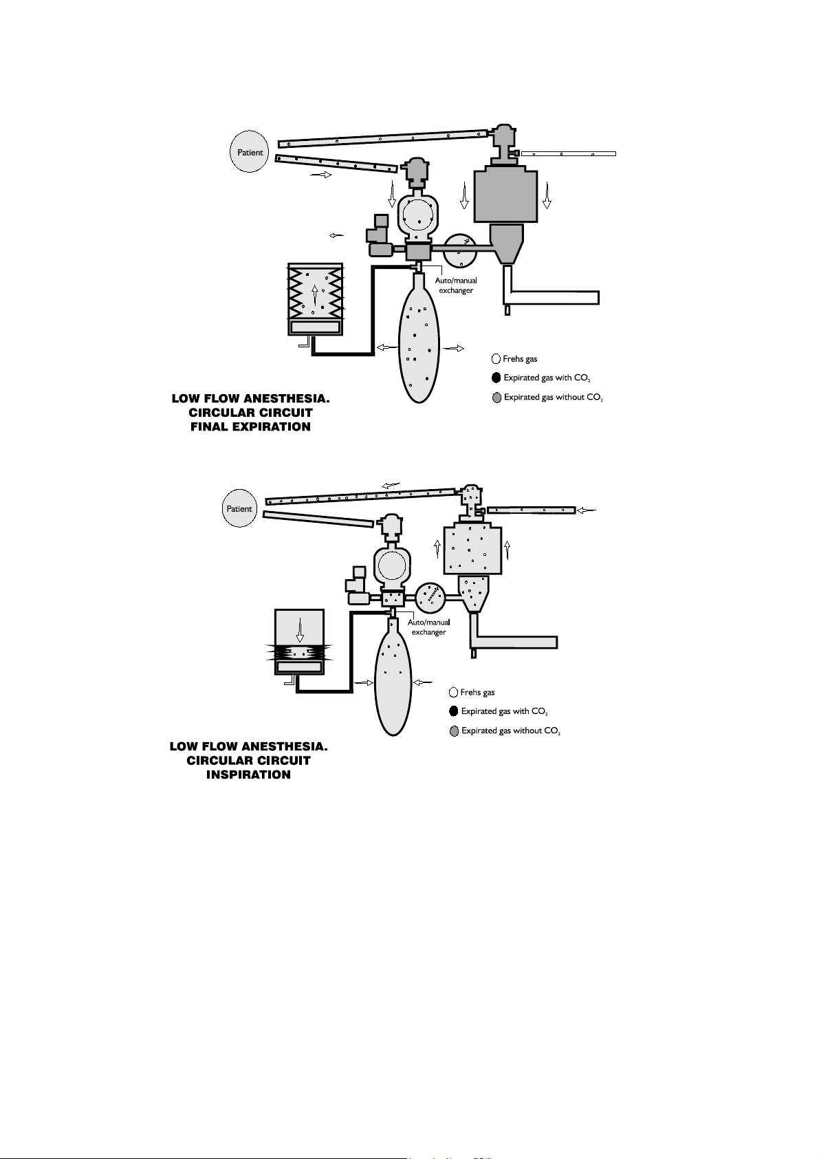
LOW FLOW ANESTHESIA
Circular Circuit
Final Expiration
Inspiration
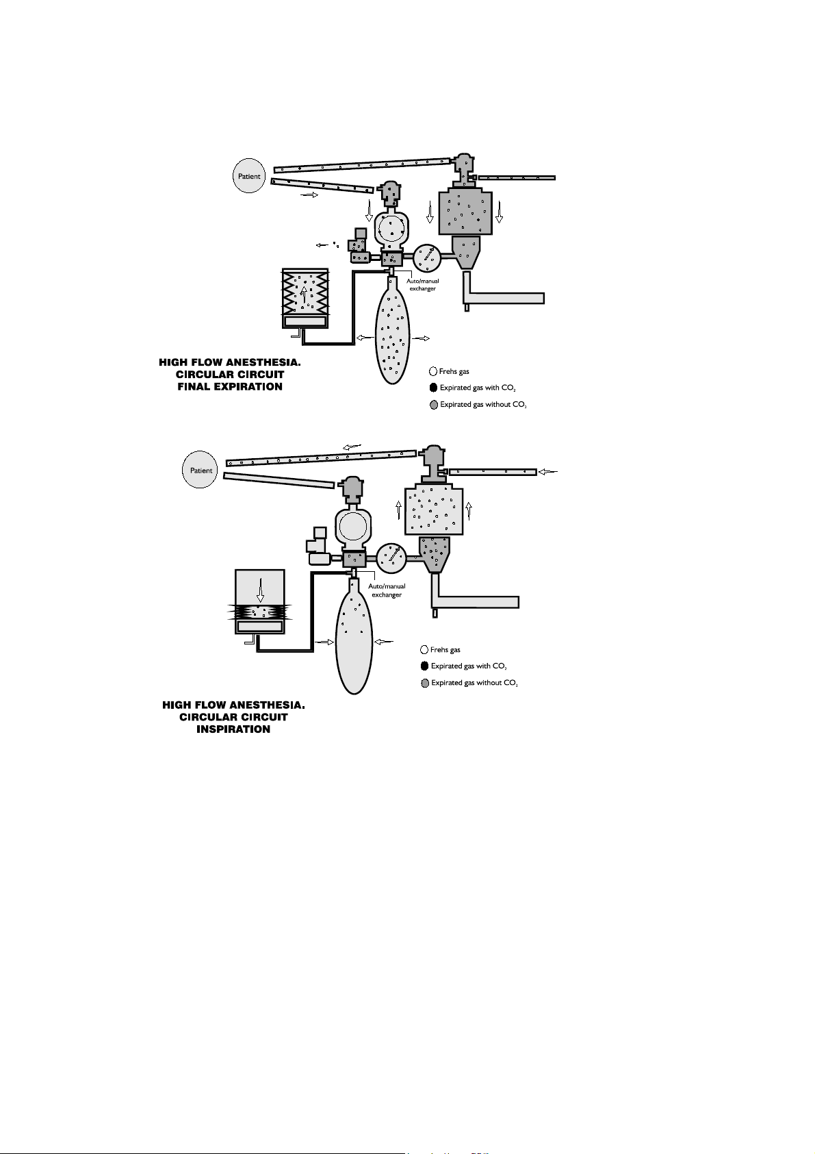
HIGH FLOW ANESTHESIA
CIRCULAR CIRCUIT
Final Expiration
Inspiration
Page 9
Page 10
Page 11
Page 12
 Loading...