

Page 1
Introduction ........................................1
Specifications ......................................1
Capacity Selection Guide ..................1
Installation
Physical installation ......................2
Electrical Installation ....................5
Operation of Humidifier ....................6
Maintenance........................................7
Unit Diagram and Parts List ..............9
Warranty ..............................Back cover
Manual for:
• Installation
• Operation
• Maintenance
Duct Mount
Rotating Drum Humidifier
Model 465-C1
Table of Contents
252911-001 9/04
CAUTION: Read installation,
operation, and maintenance
instructions carefully for safe
operation. Exercise the usual
precautions when working
with electricity.
Page 2
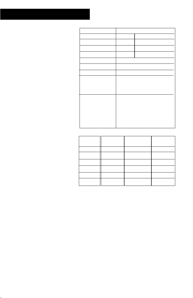
Type of Unit Rotating Drum
Duct Mounting Return Supply
GPD @ 140 ° F 22.5 17.1
GPD @ 120 ° F 16.5 12.4
GPD @ 100 ° F 10.6 7.8
Voltage 24V
Unit Dimensions 14 3/4” W x 11” D x 11 1/2” H
Duct Opening 4 5/8” x 7 5/8”
Standard Equipment Wall / duct mount humidistat
Self piercing saddle valve
7” Flange & Damper
Features • Externally held evaporative media
• Independent mounting bracket
• Right or left hand discharge
without disassembly
• All brass valve assembly
• Stainless steel cage
• Observation window in front door
• 2 year warranty
Sq. Footage
of Home
1000
1500
2000
2500
3000
4000
Tight Home
(GPD*)
0.5
3.0
5.0
7.5
10.0
14.5
Average Home
(GPD*)
5.0
10.0
14.0
19.0
23.5
33.0
Loose Home
(GPD*)
10.0
16.5
24.0
30.5
37.5
51.5
The above calculations are for reference only and are based
on the following:
• Inside temperature 70° F/35% relative humidity
• Outside Temp 20° F /70% relative humidity
• 8 foot ceiling height
• Internal moisture gain of one pound per hour
• Furnace on-time of 70%
This chart uses A.R.I. standard designations:
A “Tight Home” is assumed to be well insulated with vapor
barriers, tight storm windows and doors, and a dampered
fireplace. Air exchange rate of .50 changes per hour.
An “Average Home” is insulated and has a dampered
fireplace, but there are no vapor barriers, storm doors, or
storm windows. Air exchange rate of 1.0 change per hour.
A “Loose Home” is generally one constructed before 1930,
has little or no insulation, no storm doors, storm windows,
weather stripping or vapor barriers, and often no effective
dampering of fireplaces. Air exchange rate is as high as 1.5
changes per hour.
* Gallons Per Day (humidifier capacity)
1
Introduction
The benefits of a properly
humidified environment
(35-50% Relative Humidity)
are many. They include both
personal comfort as well as
the preservation of furniture,
draperies, carpets, wooden
floors and cabinets, paintings,
pianos, etc.. Your home will be
more comfortable at a lower
temperature (i.e.: 68° F) at 3040% Relative Humidity (RH)
than at 71° F without
controlled humidity. Since
every degree of temperature
setback represents about 3%
of heating costs, this can
represent a significant annual
savings.
During the heating season,
cold air is brought into the
home and heated. When
heated, this air dries out and
greatly increases its capacity to
hold more moisture. By using
a humidifier, a source of water
is provided to satisfy this
increased moisture holding
capability, rather than having
it drawn from our body
surface and the surrounding
furnishings in the home.
A properly maintained and
efficiently operating
humidifier is a source of
improved indoor air quality
and personal comfort. We
trust you will enjoy all the
benefits of your new
humidifier.
Introduction
Capacity Selection Guide
Specifications
Page 3
2
Physical Installation
Remember to select a location that is readily accessible for periodic inspection and
cleaning of your humidifier. This unit should be located on the cold air return side of
the system for best results. However, if space does not permit, it can be mounted on
the warm air supply side of the system. Please keep in mind that the evaporative
capacity of the humidifier will be reduced if this alternate installation method is
utilized.
CAUTION
Only a trained service person should install this humidifier. Do not connect the
unit to power source until installation is complete. A thorough checkout of the
unit installation should be completed before operation. Failure to follow these
directions may void the manufacturer’s original warranty.
Prior to installing this product...
1. Read the instructions carefully to
ensure safe operation. Failure to
follow them could damage the
product or cause personal injury,
and/or property damage..
2. Check the ratings given on the
product to make sure it is suitable for
your application.
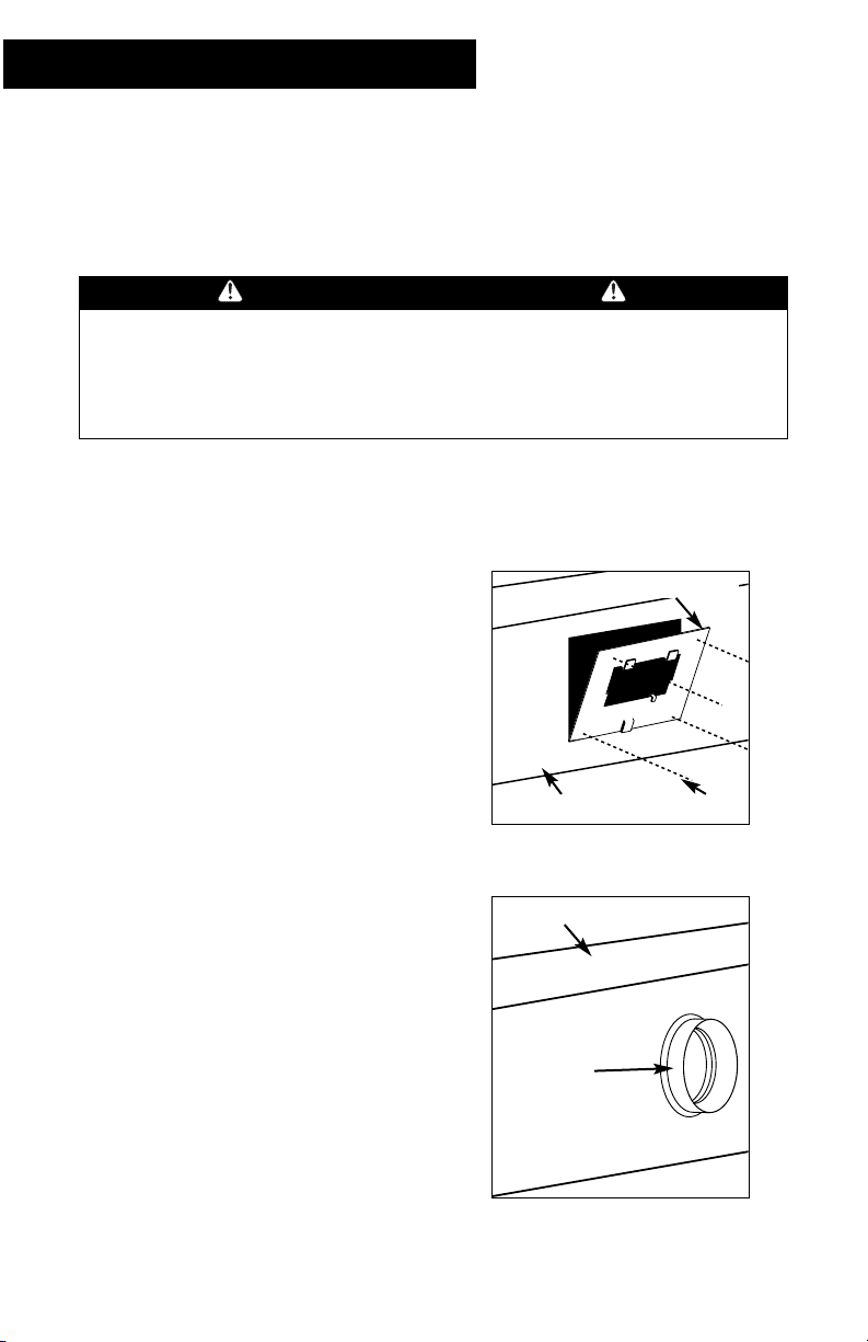
Preparing ductwork
1. Level and attach the mounting
template to the selected location.
2. Drill 1/8” diameter holes and cut the
opening as marked on the template.
Remove the template from the duct.
3. Cut a 7” diameter bypass hole in the
opposite duct using the Return Air
Flange as a template.
4. Insert the notched flange of the
Return Air Flange through the hole
and bend the tabs inside the duct to
secure the flange to the duct.
5. Position the Mounting Plate to the air
duct with (2) tangs up and (1) tang
down. If needed, position the
Damper Plate behind the Mounting
Plate.
6. Secure the Mounting Plate to the air
duct with (4) sheet metal screws and
spring nuts (provided).
Mounting plate
Duct Screws
Return air
flange
Return Air Duct
Page 4
3
Physical Installation
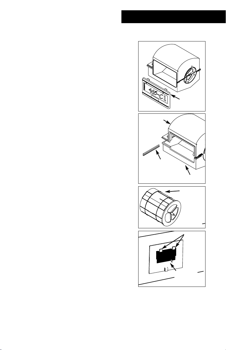
Installing Humidifier
1. Remove the window panel (panel with the
label) by sliding it up, pulling its bottom away
from the humidifier and then pulling down.
2. Separate the top half from the pan by sliding
the stainless steel retainer off the lips of the
top half and pan. Swing the pan down to
disengage the metal loops on the opposite
end.
3. Hang the top half of the unit on the (2) tangs
of the Mounting Plate.
4. The round inlet hole should be to the left or
right, as necessary.
5. The top half must be positioned so that the
step in the side opening engages the
Mounting Plate tangs which prevents lateral
movement of the unit.
6. Remove and discard packing around the drum
assembly.
7. Slide the closed end of the drum assembly onto
the motor shaft and place the other end in the
“U” shaped holder.
8. Slide the stainless steel retainer over the shaft
notch to hold the drum shaft in place.
NOTE: Do NOT use the drum to turn the motor.
Damage to the motor gears will result.
9. Latch the pan onto both metal loops at the
outlet end of the unit.
10. Swing the pan up to engage the Mounting
Plate tang. The pan will nest into the top.
11. Slide the stainless steel retainer over the lips of
the top half and pan at the water inlet end to
lock the assembly into place.
12. Install the humidistat based on the instructions
located inside the box.
13. Install the saddle valve using the instructions
on the package and turn on the water supply.
14. The water level should be 1 3/8” below the
bottom edge of the 5 1/2” diameter bypass
duct opening. If necessary, adjust the float/rod
assembly to provide the correct water level.
window
panel
Top half
Pan
Stainless steel
retainer
Drum
assembly
Mounting
plate
Tangs
Page 5

4
15. When installing this humidifier above electric
warm air heating elements or where water
damage could occur from accidental overflow,
connect a 1/2” drain hose to the brass overflow
nipple.
16. Do NOT solder the drain line directly to the
humidifier because heat can warp and damage
the pan.
17. Mount the Increaser to the unit by inserting the
small end of the Increaser into the open end of
the unit and securing with clamp.
18. Attach 7” bypass flex or metal duct (not
provided) to Increaser and Return Air Flange.
19. Insert the window panel by reversing Step #1.
Saddle valve assembly
Humidifier
Bypass duct
Air cleaner
Bypass duct
Alternate
location
"A" coil
Air cleaner
Bypass
duct
Humidifier
Air cleaner
Bypass duct
Air cleaner
Humidifier
Humidifier
Humidifier
Page 6

5
Electrical Installation
This humidifier is intended to be wired independently of the
integrated control panel on your furnace. This will provide
power to the humidifier at all times, causing the evaporator pad
drum to rotate constantly.
Read the instructions in the furnace installation manual
carefully before attempting installation or operation of this
humidifier. Failure to follow these instructions may result in an
improper installation and therefore, void the manufacturer’s
warranty.
WARNING
Improper electrical wiring can cause personal
shock, injury, or property damage. It is
required by local codes that the unit be
installed by a properly qualified HVAC
technician or electrician, following NEC and
any other local codes.
1. Turn the humidistat to the highest level (past 60%) and the
humidifier should begin to run. The humidifier should stop
when the humidistat is turned off.
2. Set the furnace controls and humidistat for the desired
conditions (30-40% RH is recommended). Operation of this
unit is automatic.
120V HOT
120V COMMON
HOUSE GROUND
FUSED FURNACE SWITCH/BLOWER
OR FUSED CIRCUIT WITH
INDEPENDENT WALL SWITCH
PLUG-IN TRANSFORMER
(NOT PROVIDED) OR
INST ALLED TRANSFORMER
LOW VOLTA GE (24 V AC)
HUMIDISTAT
HUMIDIFIER
Page 7

6
Operation
This 465-C1 humidifier operates on the silent principle of
evaporation. When your unit is operating properly, you may
observe the drum turning freely by looking through the
observation window. Evaporation takes place as the air passes
through the moistened evaporator pad held in place by the
specially engineered rotating drum assembly. Operation is
completely automatic. Working in conjunction with the
heating system blower, a portion of the warm air is bypassed
through the humidifier for quiet and economical
humidification of the air in your home. The humidifier is
designed for use with either hard or softened water.
Set the humidistat in the recommended range of 30-50%
Relative Humidity for automatic humidity control during the
heating season (a lower setting may be used to control
condensation on single pane windows). During the first
heating season, check for mineral build-up on the evaporator
pad every month to establish the proper cleaning schedule.
Clean the unit at the end of each heating season or whenever
mineral deposits appear to clog the openings in the
evaporator pad
You can easily check your humidifier to be sure it is in working
condition. Simply turn the humidistat to a higher setting and
look through the observation window (a flashlight may be
needed). If the unit is working properly, the evaporator pad
will be rotating. Be sure to set the humidistat back to the
desired level.
Summer
When shutting the humidifier down for the summer months,
start with cleaning any mineral accumulation from the unit.
Leave the water turned off and the unit dry. If the furnace fan
is to be used for cooling purposes, disconnect power to the
humidifier or turn the humidistat to the OFF position and
remove the entire evaporator pad and cage assembly.
Winter
At the beginning of the heating season, return the entire
evaporator pad and cage assembly to their original location. It
is recommended that the evaporator pad be replaced before
each heating season. Turn on the water, check the water level
within the humidifier and return the humidistat to the desired
level.
Page 8

7
Maintenance
Periodic cleaning is required for the efficient and
safe operation of this humidifier. Inspect the
humidifier approximately once a month for mineral
and algae growth. Algae may develop inside the
humidifier if certain conditions exist in the water
supplying the unit. Algae is a slimy substance which
can be green, brown or white. It is advisable to add
an algaecide to the water on a weekly basis. This
algaecide can be 10 drops of bleach or bacteriostatic
liquid/powder. Periodic cleaning and removal of
accumulated mineral deposits and algae growth is
the only required maintenance of this unit. The
frequency of this maintenance will depend on the
mineral content, or hardness, of the water being
supplied to the humidifier.
To inspect the unit:
1. Turn the electrical power to the furnace OFF.
2. Set the humidistat to the OFF position and
disconnect the humidifier from the power
source.
3. Turn off the water at the saddle valve by
turning clockwise.
4. Remove the window panel (panel with label
attached) on the front of the humidifier by
sliding it up, pulling the bottom away from the
unit and then pulling down.
To clean the unit:
1. If the evaporator pad appears clogged with
mineral deposits, remove the drain plug from
the bottom pan and drain the water from the
unit.
2. Disconnect the overflow drain line and 7”
diameter bypass duct.
3. While holding the bottom pan, slide the
stainless steel clip off the end of the humidifier.
Lower the clip end of the pan slightly and move
the pan from side to side, disengaging it from
the metal loops at the other end.
4. Remove the pan from the unit.
5. Slide the stainless steel retainer clip from the
drum shaft support at the open end of the
humidifier.
NOTE: Do not rotate the drum or damage to the
motor gear train will occur.
Note
To prevent algae, it is
advisable to add an
algaecide to the water
on a weekly basis.
Page 9

8
Maintenance
6. Lift the drum shaft out of the support and slide the
drum away from the motor, then down and away from
unit.
7. Dump any accumulated sludge or slime from the pan.
Clean thoroughly using a 50/50 solution of white vinegar
and water or liquid humidifier cleaner. Thoroughly rinse
with clean water.
8. Remove the evaporator drum ends by squeezing the
loop ends of the wire cage.
9. Coil the evaporator pad to free it from the wire cage.
10. Install the new evaporator pad by coiling the pad and
inserting it into the wire cage. Uncoil the pad and butt
the ends together.
11. Remount the evaporator drum ends by reversing step 8.
12. Re-install the drum assembly into the humidifier and
replace the drain plug.
13. Latch the pan onto both metal loops at the outlet end of
the unit.
14. Swing the pan up to engage the Mounting Plate tang.
The pan will nest into the top.
15. Slide the stainless steel retainer over the lips of the top
half and pan at the water inlet end of the unit to lock
the assembly into place.
16. Re-install the 7” diameter bypass duct.
17. Reconnect the overflow drain line and turn on the water
at the saddle valve by turning counter clockwise. The
water level should be 1 3/8” below the edge of the 5 1/2”
diameter bypass duct opening.
18. Replace the window panel on the front of the humidifier
by sliding it up into the window frame, and sliding it
down to secure.
19. Set the humidistat to the desired humidity level.
20. Connect the humidifier to the power source and turn
electrical power to the furnace ON.
Page 10

9
21
20
2
7
1
3
8
9
10
11
12
13
14
18
16
17
15
4
19
23
22
6
5
Unit Diagram
Page 11

10
Model 465 C-1
Assembly Part Number
352440-001C
Item Descripton P/N Remarks
1Top 1201BP
2 Motor 1322P 24V 50/60HZ
3 Float & valve assembly 1210P
4Washer FV-17 Fiber
5 Brass Locknut FV-10 7/16-24
6 Brass Compression Sleeve FV-11
7 Brass Compression Nut FV-12
8Closed End 1221
9 Cage 1219
10 Evaporator Pad 1220P
11 Open End 1222
12 Drum Bearing 1223
13 Bracket 1213
14 Drum Bearing Clip 1316
15 Outlet Clamp 251040-001
16 Pan 1224P
17 Drain Plug 2408B
18 Retainer 1225
19 Front Panel Assembly 1226A
20 Mounting Plate 351038-001
21 Damper Plate 1297
22 Increaser 1294
23 Return Air Flange 1296
24 Humidistat 352680-004C Not shown
Parts List
Page 12

Warranty
Humidifier Limited Two Year Warranty
This limited warranty covers Herrmidifier Residential Type Humidifiers, excluding duct work, wiring
and installation. The manufacturer warrants that all new Herrmidifier Humidifiers are free from
defects in material and workmanship under normal, non-commercial use and service. The
manufacturer will remedy any covered defects if they appear within 24 months from the date of
original installation as evidenced by proof of purchase, subject to the terms and conditions of this
Limited Two-Year Warranty stated below:
1. THIS LIMITED TWO-YEAR WARRANTY is granted by CareCo, 415 W. Wabash Ave., P.O. Box
200, Effingham, IL 62401.
2. This warranty shall extend only to any non-commercial owner who has purchased the
residential humidifier other than for purposes of resale.
3. All components are covered by this limited warranty except expendable items, such as
evaporative pads, media filter pads and nozzles.
4. If, within the warranty period, any Herrmidifier residential humidifier unit or component
requires service, it must be performed by a competent heating and/or air conditioning
contractor (preferably the installing contractor). CareCo will not pay shipping charges or
labor charges to remove or replace such defective parts or components. If the part or
component is found by inspection to contain such defective material and workmanship it will
be either repaired or exchanged free of charge at CareCo's option, and returned freight
collect.
5. In order to obtain the benefits of this limited two-year warranty, the owner must notify the
dealer or distributor of any defect within 30 days of its discovery. If after reasonable time you
have not received an adequate response from the dealer or distributor, notify in writing
CareCo Service Dept., 415 Wabash Ave., P.O. Box 200, Effingham, Illinois, 62401, or
call 1-866-829-2440 or email
fiaqcustomerservice@fedders.com. Humidifiers which have been installed or become
part of real estate cannot be returned. CareCo will receive, freight prepaid, only removable
parts or components of such defective humidifiers.
6. This limited warranty does not apply to any part or component that is damaged in transit or
in handling, has been subject to misuse, neglect or accident; has not been installed, operated
and serviced according to Herrmidifier's instructions; has been operated beyond the factory
rated capacity; or altered in any such way that its performance is affected. There is no
warranty due to neglect, alteration or ordinary wear and tear. Herrmidifier's liability is
limited to replacement of defective parts or components and does not include the payment
of the cost of labor charges to remove or replace such defective components or parts.
7. CareCo will not be responsible for loss of use of any product; loss of time, inconvenience, or
any other indirect, incidental or consequential damages with respect to person or property,
whether as a result of breach of warranty, neglect or otherwise. SOME STATES DO NOT
ALLOW THE EXCLUSION OR LIMITATION OF INCIDENTAL OR CONSEQUENTIAL DAMAGES, SO
THE LIMITATION OR EXCLUSION IN THE PRECEDING SENTENCE MAY NOT APPLY TO YOU.
8. THIS WARRANTY GIVES YOU SPECIFIC RIGHTS, AND YOU MAY ALSO HAVE OTHER RIGHTS
WHICH VARY FROM STATE TO STATE.
9. Any warranty by CareCo of merchantability, fitness for use or any other warranty (express,
implied or statutory), representation or guarantee other than those set forth herein, shall
expire at the expiration date of this express limited warranty. SOME STATES DO NOT ALLOW
LIMITATIONS ON HOW LONG AN IMPLIED WARRANTY LASTS, SO THE LIMITATION IN THE
PRECEDING SENTENCE MAY NOT APPLY TO YOU.
10. Herrmidifier reserves the right to make changes in the design and material of its products
without incurring any obligation to incorporate such changes in units completed on the
effective date of such change.
CareCo Service Dept.,
415 Wabash Ave., P.O. Box 200, Effingham, Illinois, 62401
Phone: 1-866-829-2440
E-mail: fiaqcustomerservice@fedders.com
 Loading...