

Page 1

Engineered Humidification Systems
READ AND SAVE THESE INSTRUCTIONS
Herrtronic® MDD
Supplemental Manual
Herrmidifier® | www.herrmidifier-hvac.com
Page 2

Installation, Operation, & Maintenance Manual
TABLE OF CONTENTS
I. Preface ..............................................................................................................................................3
II. Unit Operation ...................................................................................................................................3
Product Diagram ......................................................................................................................... 3
III. Mounting Instructions .......................................................................................................................4
Mounting Location ....................................................................................................................... 4
Unit Dimensional Data ................................................................................................................4
IV. Plumbing Instructions ...................................................................................................................... 5
Bottom View – Plumbing Connections ........................................................................................ 5
Drain Diagram ............................................................................................................................. 6
V. Steam Distribution ............................................................................................................................ 7
VI. Supply Power ..................................................................................................................................7
Steam Output Chart .................................................................................................................... 7
VII. MDD Control Circuit Connections ..................................................................................................7
Dependent Control ...................................................................................................................... 7
Independent Control ...................................................................................................................7
Electrical Compartment ............................................................................................................... 7
VIII. Factory Wiring Between the Master and Slave Controls ............................................................... 8
Dependent Controls .................................................................................................................... 8
Independent Controls .................................................................................................................. 8
IX. Turning the Master and Slave “ON” After Servicing the Unit ........................................................... 8
X. Plumbing Components Diagram ......................................................................................................9
XI. Plumbing Components Parts List .................................................................................................... 9
XII. Electrical Components Diagram ..................................................................................................... 10
XIII. Electrical Components Parts List ..................................................................................................10
XIV. Wiring Diagram (208/230/460) ...................................................................................................... 12
XV. Alternate Wiring Diagram (For units with 380 or 600 Volt Primary Circuits) ................................... 14
2 www.herrmidifier-hvac.com
Herrtronic® MDD Supplement
Page 3

Installation, Operation, & Maintenance Manual
I. PREFACE
These instructions are designed to cover the specic differences in the installation of a Herrmidier Herrtronic MDD Electronic Steam
Humidier (110-250 lbs/hr. unit) versus an MDM or MDS Electronic Steam Humidier (5-100 lbs/hr. unit). These instructions are to
be used in conjunction with the Herrtronic MD Series Installation and Operations Manual (OM-93) as there are cross references
between that manual and this supplement. The primary intent of this supplement is to deal with the installation differences between
the MDD and the MDS or MDM. The operating, start-up and troubleshooting sections are common to all the MD’s and can be found
in the Herrtronic MD Series Installation and Operations Manual (OM-93). The one exception to this is the fact that you must turn
on both the master and the slave unit with their respective “On/Off” button.
II. UNIT OPERATION
All MDD units are operationally tested before shipment. They have been setup and run with the control signal and power supply spec-
ied on the purchase order. Any changes in power supply or control technique will cause the unit to require changes prior to start-up.
All MDD units have two steam cylinders, two ll assemblies, two drain assemblies, two sets of power contactors, two main circuit
boards and one display board. There are two knockouts for power wiring, a knockout for control wiring, one water inlet, two steam
cylinder drains, and two cabinet drains. The steam cylinder on the right is the master and the one on the left is the slave. Simply put,
the components for two independent steam boilers are housed in one cabinet.
Steam Hose Outlets
Slave Section
Steam Cylinder Assembly
Drain Assembly
Steam Hose Outlets
Master Section
Steam Cylinder Assembly
(2) Fill Assemblies
Drain Assembly
Electrical Section
Contactors
Transformers
Cylinder Interface
Terminal Blocks
Circuit Boards - Master
Slave
Display
Power wiring
Plumbing Connections
(2) Steam Cyliner/Cabinet Drains
Controls
Wiring
Plumbing Connections
(1) Water Inlet
Figure 1
As mentioned earlier, there are two main circuit boards, and one display board. The master and slave control board keypads are
accessible through the front panel. Communication between the Master and the Slave is accomplished through the networking
capability of the main circuit board (Page 15, MD IOM). The address of the master will always be 00 and the address of the slave
will always be 01. Each cylinder (Master or Slave) will ll, boil, and drain independently, based on the commands from their respective main circuit board. Establishing set points, operating the units, fault reporting and general monitoring of performance for both
Master & Slave is typically done from the master control keypad and display using menu 4 of the master control. When in menu 4 of
the Master, access the Slave and use the Master keypad to make any necessary changes to the Slave control board. (See step 13
Operating Instructions of MD Manual.)
Herrtronic® MDD Supplement
www.herrmidifier-hvac.com
3
Page 4

Installation, Operation, & Maintenance Manual
III. MOUNTING INSTRUCTIONS
The Operating Weight of the MDD Series is 258 lbs. See Page 6 of the MD IOM for further information.
16.00
4.00
3.00
22.38
1.81 21.89 17.00
Figure 2 - Mounting Location (Back View of Unit)
5-3/4"
6.2516.004.25
.75 Typ.
Ø.38" x Ø.75"
Keyhole Slot
Typ.
Ø.25 Typ.
28"
19 5/16"
11 1/2"
REF.
4"
17"
4"
Steam Outlet
1 1/2" I.D. Hose
(4 places)
3"
43"
Recessed Bottom
Figure 3 - Unit Dimensions
4 www.herrmidifier-hvac.com
Herrtronic® MDD Supplement
Page 5

Installation, Operation, & Maintenance Manual
IV. PLUMBING INSTRUCTIONS
Figure 4 details the unit’s plumbing connections. All plumbing connections are through the bottom of the unit. There are two unit
drains and one ll connection.
33 1/8"
Fill Connection
1/4" Compression
4 1/4"
17"
2"
Knockout for
Control Wiring
(7/8 X 1 1/8)
2 11/32"
Typ.
Unit/Cabinet Drain Resevoir
3/4" I.D. Hose
2 19/32""
Typ.
Figure 4 - Plumbing Connections
17"
16"
3"
3"
6 1/2"
(2) Knockouts
for Main Power Supply
(1 1/4 x 1 3/4)
Herrtronic® MDD Supplement
www.herrmidifier-hvac.com
5
Page 6

Installation, Operation, & Maintenance Manual
MASTER DRAIN RESEVOIR
Figure 5 - Drain Diagram
3/4" MIN. I.D./1" MAX O.D.
FLEXIBLE DRAIN CONNECTION
SLAVE DRAIN RESEVOIR
8"
RECOMMENDED
T YP.
BALANCE OF DRAIN LINE TO BE 1" MIN. I.D.
WITH A MINIMUM PITCH OF 1/8" PER 12" OF RUN
4"
RECOMMENDED TYP.
6" MIN. LENGTH OF 1-1/4" MIN. I.D. COPPER LINE.
IF PVC IS USED, LOCAL CODES REQUIRE A LOWER
TEMPERATURE DRAIN WATER IS NOT UNCOMMON.
6 www.herrmidifier-hvac.com
6" MIN. LENGTH OF 1-1/4" MIN. I.D. COPPER LINE.
IF PVC IS USED, LOCAL CODES REQUIRE A LOWER
TEMPERATURE DRAIN WATER IS NOT UNCOMMON.
BALANCE OF DRAIN LINE TO BE 1" MIN. I.D.
WITH A MINIMUM PITCH OF 1/8" PER 12" OF RUN
Herrtronic® MDD Supplement
Page 7
Installation, Operation, & Maintenance Manual
V. STEAM DISTRIBUTION
Refer to Herrtronic MD IOM for detailed instructions. See Figure 3 on page 9 – Unit Dimensional Data for steam outlet locations.
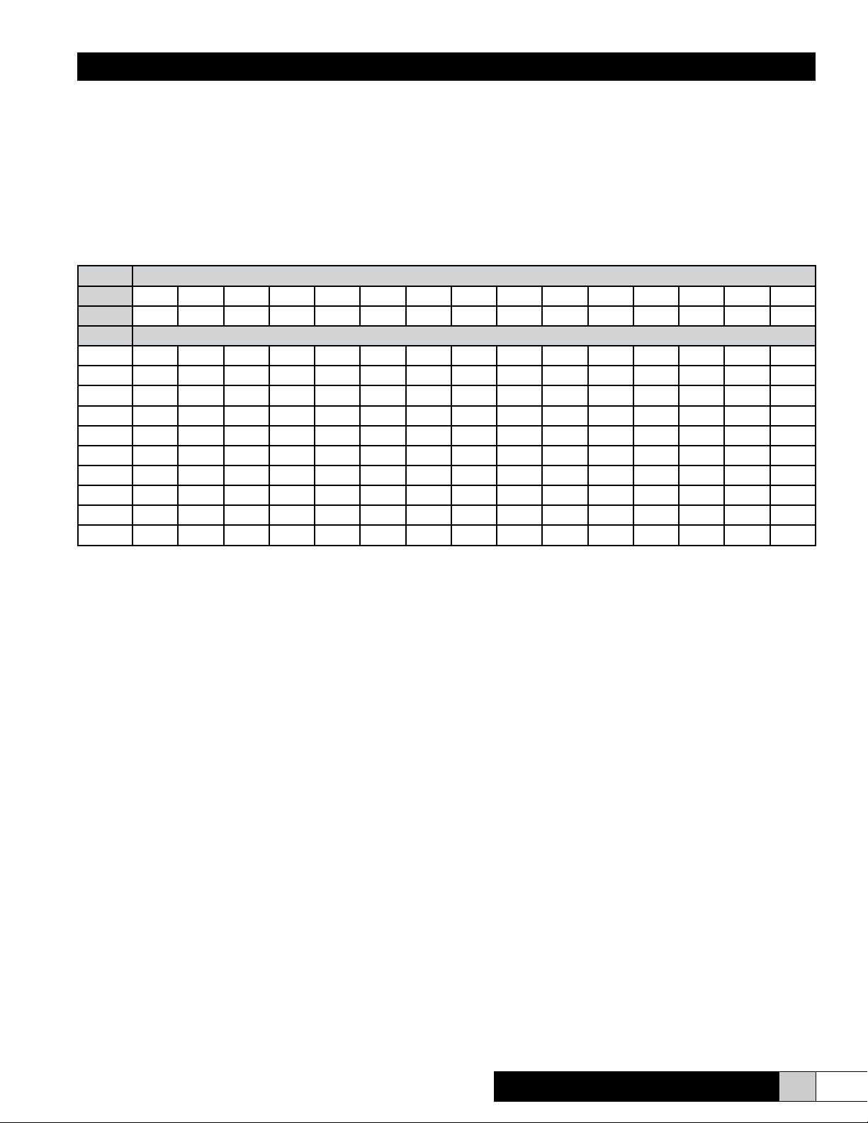
VI. SUPPLY POWER
Power Block is supplied in the lower right hand side of the electrical compartment for eld connection of the main power supply legs
(always three phase) and a ground wire. Engineering Data: Steam Output / Electrical Characteristics
Figure 6 - Steam Output/Electrical Characteristics:
Steam Output
Lb/hr 110 120 130 140 150 160 170 180 190 200 210 220 230 240 250
Kg/hr 50.0 54.4 59.1 63.6 68.2 72.6 77.3 81.7 86.4 90.9 95.5 100 104.5 109.1 113.6
Voltage Electrode Current (amps)
208
101.7A 110.9A 120.2A 129.4A 138.6A 147.9A 157.1A 166.4A 175.6A 184.9A
220
230
240
380
440
460
480
575
600
KW = .333 X Lbs/Hr
Amps(3Ph) = KW X 1000 / (Voltage X 1.732)
Min. Circuit Ampacity = 1.25 X Rated Electrode Current (Note: with RDU add .5 Amps @ 208/240 Volts or add .25 Amps @ 480 Volts)
Minimum Circuit Ampacity determines wire size (AWG)
96.1A 104.9A 113.6A 122.3A 131.1A 139.8A 148.6A 157.3A 166.0A 174.8A
91.9A 100.3A 108.7A 117.0A 125.4A 133.7A 142.1A 150.5A 158.8A 167.2A
88.1A 96.1A 104.1A 112.2A 120.2A 128.2A 136.2A 144.2A 152.2A 160.2A
55.7A 60.7A 65.8A 70.8A 75.9A 81.0A 86.0A 91.1A 96.1A 101.2A 106.2A 111.3A 116.4A 121.4A 126.5A
48.1A 52.4A 56.8A 61.2A 65.5A 69.9A 74.3A 78.7A 83.0A 87.4A 91.8A 96.1A 100.5A 104.9A 109.2A
46.0A 50.2A 54.3A 58.5A 62.7A 66.9A 71.1A 75.2A 79.4A 83.6A 87.8A 91.9A 96.1A 100.3A 104.5A
44.1A 48.1A 52.1A 56.1A 60.1A 64.1A 68.1A 72.1A 76.1A 80.1A 84.1A 88.1A 92.1A 96.1A 100.1A
36.8A 40.1A 43.5A 46.8A 50.2A 53.5A 56.8A 60.2A 63.5A 66.9A 70.2A 73.6A 76.9A 80.2A 83.6A
35.2A 38.5A 41.7A 44.9A 48.1A 51.3A 54.5A 57.7A 60.9A 64.1A 67.3A 70.5A 73.7A 76.9A 80.1A
Refer to Herrtronic MD Installation, Operation, & Service manual for additional information.
VII. MDD CONTROL CIRCUIT CONNECTIONS
Dependent Control
This is the typical control circuit application for the MDD units. In this conguration, the MASTER and SLAVE equally share the total
output That is, for a 140 lbs/hr. MDD, the MASTER will produce 70 lbs/hr. and the SLAVE will also produce 70 lbs/hr. If the MDD
has the capability to modulate its output (MDDI or MDDP), the output of the MASTER and the SLAVE will remain equal throughout
the proportioning range.
The Dependent MDD requires one set of controls; a control input, a recommended limit input and air proving switch. See pages 10
and 11 of the MD IOM for proper placement of the control wires to the appropriate pole(s) on the master unit terminal strip.
Independent Control
In this conguration, the MASTER and the SLAVE may be rated for different output capacities. The data plate will reect the combined output and current draw. If the output capacities of the MASTER and SLAVE are different, the MASTER will always be the
larger of the two unless specied otherwise when ordering.
The Independent MDD requires two sets of controls; two control inputs along with the recommended individual limit inputs and air
proving switches. The MASTER and SLAVE input connections will be made on their respective terminal strips (Figure 7). Refer to
the Control Circuit Connections section of the MD IOM (pages 10 and 11) for proper terminal connections for your particular type of
controls. The units will operate independently of one another, with the circuit boards responding to their individual inputs.
Herrtronic® MDD Supplement
www.herrmidifier-hvac.com
7
Page 8

Installation, Operation, & Maintenance Manual
MASTER TERMINAL STRIP
DISCONNECT THE POWER
CAUTION:
SUPPLY BEFORE SERVICING
ATTENTION:
DECONNECTER DU
CIRCUIT D'ALIMENTATION
ELECTRIQUE AVANT L'ENTRETIEN
1 32 4 65 1 32 654
2
50 to 600 VAC
50/60 Hz
EST1003PB
Control
24
PCB
VAC
3
4
1
2
50 to 600 VAC
50/60 Hz
EST
003PB
24
Control
VAC
SLAVE BOARD
COMMON DISPLAY
MASTER BOARD
PCB
4
3
1 3 5 7 119
82 64 1210
SLAVE TERMINAL STRIP
WARNING
TO REDUCE THE RISK
OF FIRE, REPLACE
ONLY WITH THE SAME
TYPE 2 AMP FUSE.
WARNING
TO REDUCE THE RISK
OF FIRE, REPLACE
ONLY WITH THE SAME
TYPE 4 AMP FUSE.
2 4 6 8
7531
119
1210
CAUTION
USE SUPPLY WIRING
SUITABLE FOR 90°C
USE COPPER CONDUCTORS ONLY
FOLLOW TORQUE REQUIREMENTS
LISTED ON THE SIDE OF THE
POWER BLOCK.
ETL LISTED
HUMIDIFIERS
Conforms to
R
LISTED
ANSI/UL-998
33964
ETL TESTING LABORATORIES, INC.
CORTLAND, NEW YORK 13045
MODEL NO.
VOLTS/Ph/Hz
/ /
AMPS
MAX.
MAX.
LBS/HR
/ /
SER.NO.
DATE
HERRTRONIC
TRION INC.
HERRMIDIFIER
A TRION Company
SANFORD, NC USA
Figure 7 - Electrical Compartment
VIII. FACTORY WIRING BETWEEN THE MASTER AND SLAVE CONTROLS
Dependent Controls: Factory Wiring Included the Following:
1. Jumpers between Master terminal strip, terminals 11 & 12 to the Slave terminal strip, terminals 11 & 12. This wiring allows communication from the Master to the Slave via the Master Keypad, utilizing the communication functions of Menu 4 in the Master
menu.
2. Jumpers between Master terminal strip, terminal 2 to the Slave terminal strip, terminal 2. This wiring allows the use of an optional
air ow switch wired to the Slave terminal strip. This wire would negate the use of second air ow switch.
3. For Proportional and Proportional/Integral Control Units Only (See MDD wiring diagram). Wiring from the Master Molex connector J1, terminals 1 & 2 to the Slave terminal strip, terminals 4 & 5. This wiring passes the humidity sensor or BMS control input
that has been received by the Master to the Slave control board. This allows the Slave to “share” the control input with the Master
and operate in parallel with the Master.
4. For On/Off Control Units Only (See MDD wiring diagram). Wiring from Master terminal strip, terminal 5 to the Slave terminal
strip, terminal 5. This wiring passes the On/Off control signal that has been received by the Master to the Slave control board.
Independent Control: Factory Wiring Includes the Following:
1. Jumpers between Master terminal strip, terminals 11 & 12 to the Salve terminal strip, terminals 11 & 12. This wiring allows
communication from the Master to the Slave via the Master keypad, utilizing the communication functions of Menu 4 in the
Master menu.
IX. TURNING THE MASTER AND SLAVE “ON” AFTER SERVICING THE UNIT
During servicing, the Master and Slave cabinet access doors are typically removed to gain access to the unit. Both of these cabinets have a door interlock switch for safety purposes. Whether the door interlock switches are taped closed or jumped-out during
service, when the tape/jumpers are removed from the interlock switches, and the cabinet access doors are re-installed following
maintenance, BOTH THE MASTER AND SLAVE MUST BE TURNED “ON” at the keypad to put the unit back in service. Both the
Master and Slave must be in the Menu 1 default menu for “on/off” button to work. If only the Master is turned ON, the Slave cabinet
will remain inoperative.
Prevent the unit from operating at only 50% capacity by ensuring that BOTH THE MASTER AND SLAVE ARE
TURNED “ON” after servicing the equipment.
Options for Turning ON/OFF Slave:
1. Use “Slave” On/Off button
2. Use “Master” Keypad to address “Slave” via communications. (Menu #4)
8 www.herrmidifier-hvac.com
Herrtronic® MDD Supplement
Page 9

Installation, Operation, & Maintenance Manual
Model MDD - Plumbing Components
EST-122-1
X. PLUMBING COMPONENTS PARTS LIST
X. PLUMBING COMPONENTS DIAGRAM
EST-1092
DRAIN KIT
ASSEMBLY
354537-001
DRAIN SUB-ASSEMBLY
120096-003
EST-1080
EST-076
EST-1225-KIT
EST-1060-3
454320-001
EST-165
EST-1002-6-2
1845
EST-117
EST-1092
DRAIN KIT
ASSEMBLY
EST-1225-KIT
354537-001
DRAIN SUB-ASSEMBLY
EST-1080
FV-12 (INCLUDED w/4060)
PART OF 4060
121078-011
EST-076
EST-165
MASTER
FILL SUB-ASSEMBLY
354415-002
FV-11 (INCLUDED w/4060)
121078-011
4060
120096-003
1845
GT-116
GT-118
GT-116
GT-153
SLAVE FILL SUB-ASSEMBLY
354538-001
GT-116
GT-118
EST-117
EST-122-1
XI. PLUMBING COMPONENT PARTS LIST
EST-076 Lock Washer, Stainless Steel
EST-117 Grommet, Steam Hose
EST-122-1 Cabinet Lock with Keys
EST-165 Steam Hose Clamp
EST-171 Steam Hose, 1-1/2" Diameter
EST-1002-6-2
Steam Cylinder
EST-1060-3 "O" Ring, 13/16 x 1-1/16"
EST-1080 Electrode Knob
EST-1092 Drain Kit Assembly
EST-1225-KIT Drain Reservoir Kit
FV-11 Sleeve, Brass, 1/4" Compression
FV-12 Brass Compression Nut
EST-1002-6-2
EST-1060-3
454320-001
GT-116 Celcon Compression Nut
GT-118 Metering Fill Solenoid
GT-153 Strainer
1845 Door Interlock Switch
4060 1/4" Compression x 1/4"
Compression Brass Bulkhead Union
120096-003 Hole Plug
121078-011 Sealing Washer
354415-002 Master Fill Sub-assembly
354537-001 Drain Sub-assembly
354538-001 Slave Fill Sub-assembly
Herrtronic® MDD Supplement
www.herrmidifier-hvac.com
9
Page 10
Installation, Operation, & Maintenance Manual
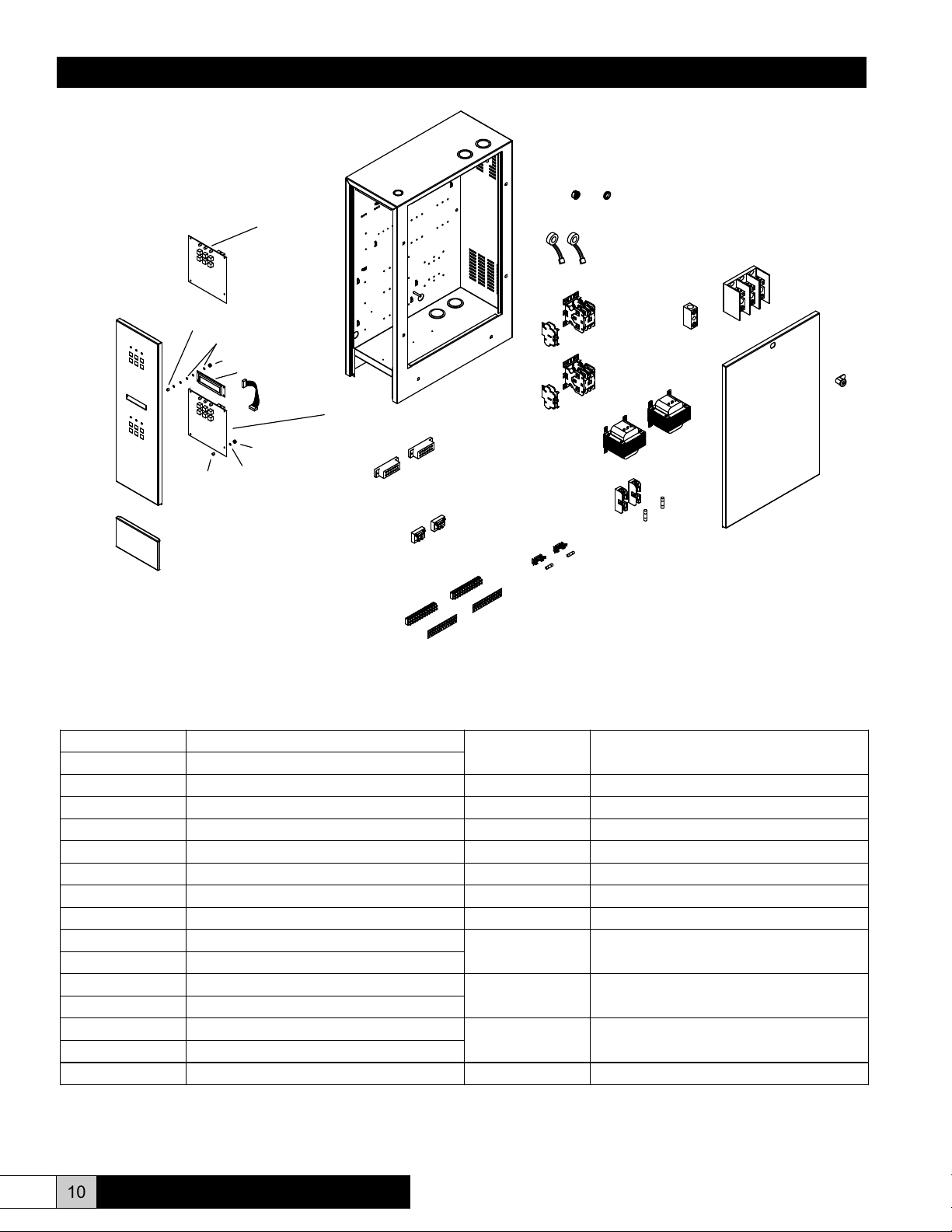
MDD ELECTRICAL COMPONENTS
XII. ELECTRICAL COMPONENTS PARTS LIST
XII. ELECTRICAL COMPONENT DIAGRAM
EST-1409
EST-1127
EST-1127
EST-1250
SLAVE
EST-1136
121800-001
265171-001
EST-1368
EST-1250
MASTER
121800-001
EST-1136
EST-1123
EST-003B
EST-1124-1
EST-105A
EST-109-2
155045-001
EST-1612
EST-353
EST-109
or
EST-109-3
141622-001
EST-120 (4A)
or
158481-001 (6-1/4A)
EST-239
259097-001
or
255991-001
or
253402-002
141622-001
EST-354
EST-354
EST-236 (175A)
or
EST-237 (335A)
454320-001
EST-122-1
XIII. ELECTRICAL COMPONENT PARTS LIST
EST-003B Cylinder Full Interface
EST-1250
EST-105A Toroid Transformer
EST-109 Contactor, 3-Pole, 40 Amp
EST-109-2 Auxiliary Contact, 24 VAC
EST-109-3 Contactor, 3-Pole, 65 Amp
EST-120 Control Fuse, 4 Amp
EST-122-1 Cabinet Lock with Keys
EST-236 Power Block, 175 Amp
EST-237 Power Block, 335 Amp
EST-239 Ground Block
EST-1368
EST-1409
EST-1612 Marking Strip for EST-1124-1
121800-001 KEP Nut, #4-40
141622-001 High Voltage Fuse Holder
155045-001 Fuse Holder
158481-001 Control Fuse, 6-1/4 Amp
253402-002 Control Transformer, 208/230/
EST-353 Shorty Bushing
EST-354 High Voltage Fuse, 2 Amp
255991-001 Control Transformer, 208/230/
EST-1123 Terminal Block, 12 Position
EST-1124-1 Terminal Strip, 12-Pole
259097-001 Control Transformer, 208/230/
EST-1127 Spacer, Nylon, #6
EST-1136 Washer, Nylon, #6
265171-001 LCD Display
Microprocessor Board. Provide Specic
Model # and Control Arrangement.
Ribbon Cable Assembly for LCD Display
Universal Bushing
240/460/480V Primary, 150VA
380/460/600V Primary, 96VA
460V Primary, 100VA
10 www.herrmidifier-hvac.com
Herrtronic® MDD Supplement
Page 11

Installation, Operation, & Maintenance Manual
THIS PAGE INTENTIONALLY LEFT BLANK
Herrtronic® MDD Supplement
www.herrmidifier-hvac.com
11
Page 12
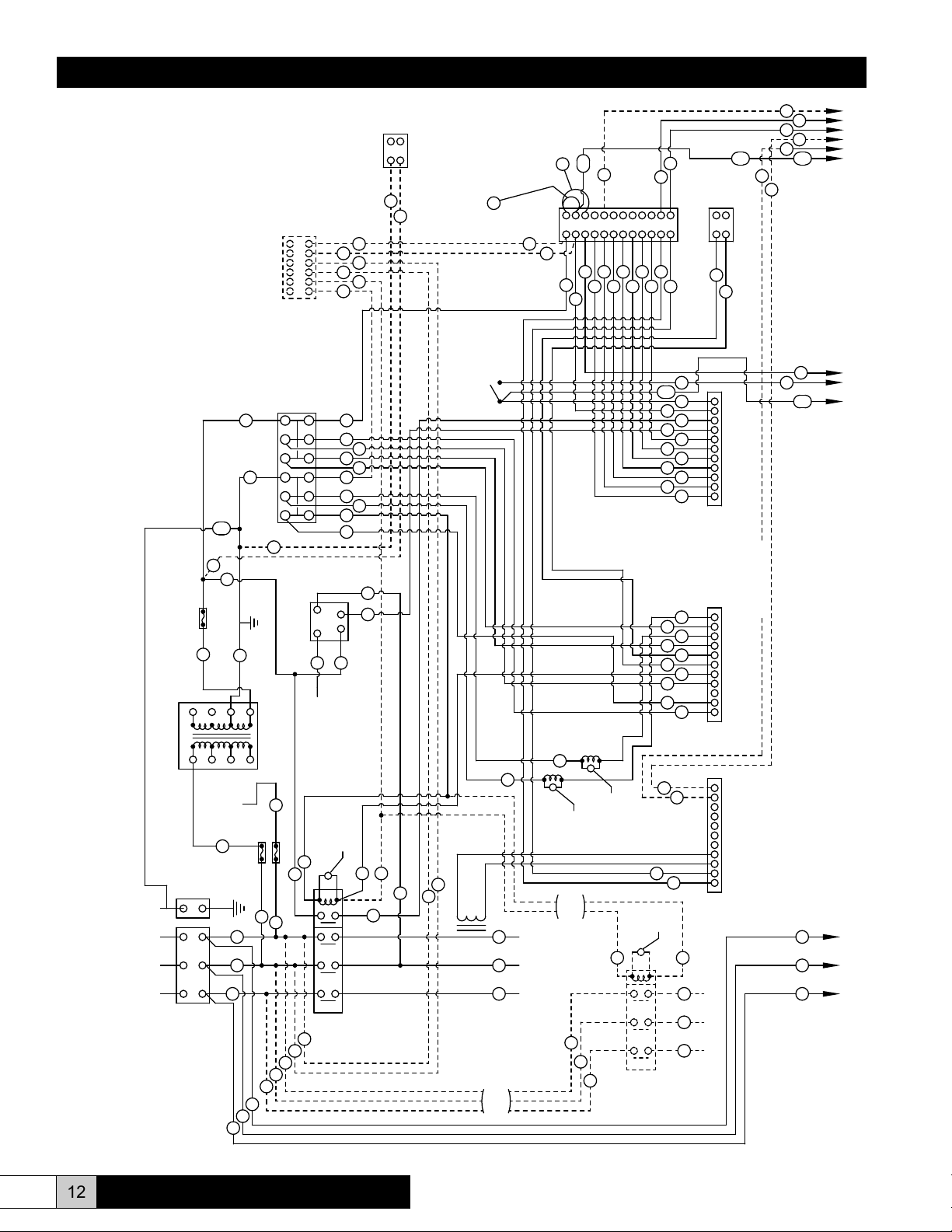
Installation, Operation, & Maintenance Manual
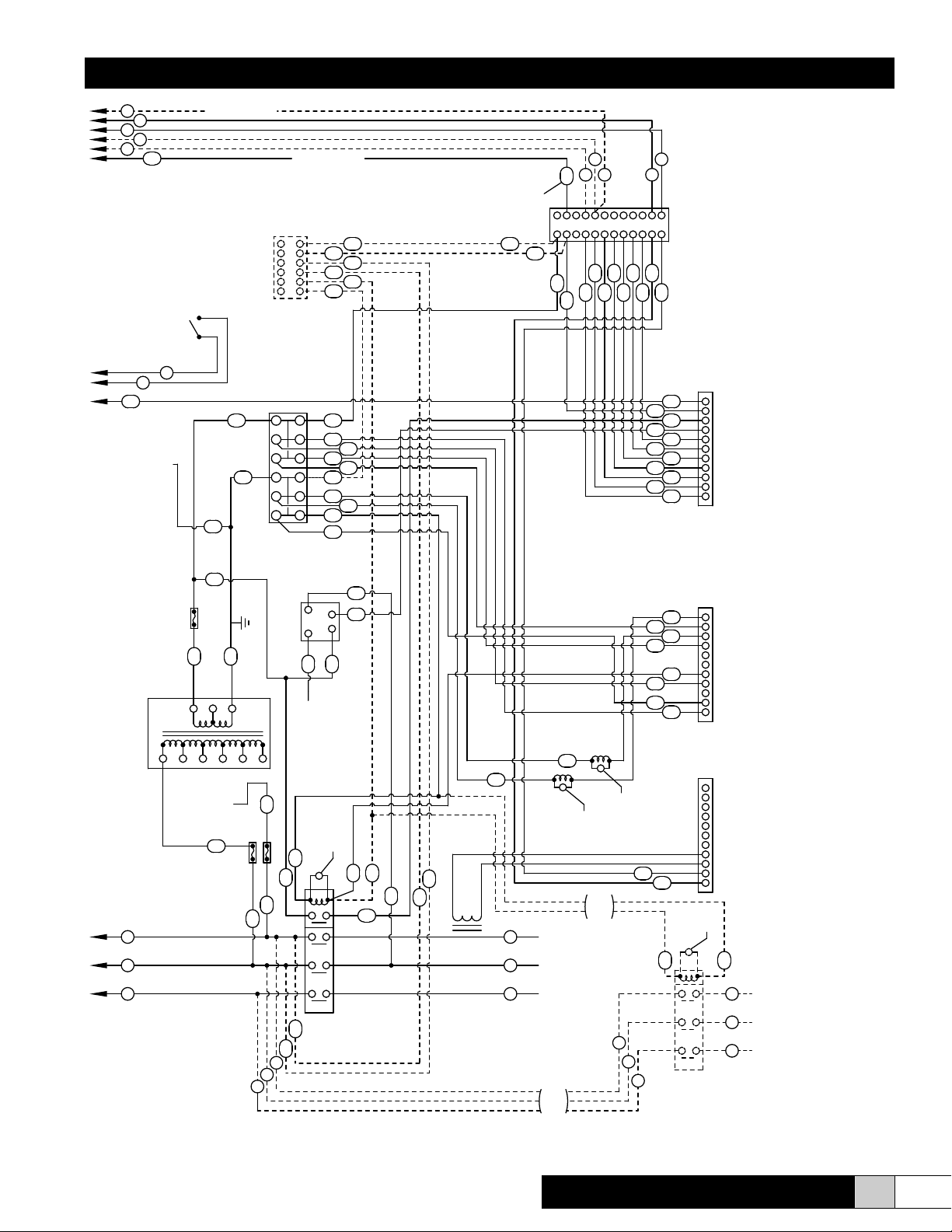
MDD WIRING DIAGRAM
SLAVE SECTION
(TL)
BLK
S
BLK
BLK
U
BLK
T
BLK
129
BLK
130
BLK
(TR)
131
BLK
BLK
3
1
5
7
9
11
126
128
BLK
114
126
WHT
127
BLK
TERMINAL STRIP 5
(RDU)
FUSE 5
(2A)
FUSE 4
(2A)
BLK
132
(COM) (NO)
INTERLOCK 2
DOOR
BLK
option2
TO GND LUG
480
230
X3
208
0
X1
XF
X2
TRANSFORMER
VOLTAGE LEG OF
TO INCOMING LINE
WIRE #132 CONNECTED
IF FUSE IS MOUNTED ON TRANSFORMER
AND 127 CONNECT TO TRANSFORMER
WIRE 128 IS OMITTED AND WIRES 114
TERMINAL XF
(24 VAC)
BLK
FUSE 6
BLK
(4 A FOR 100 VA)
(6 1/4 A FOR 150 VA)
WHT
(24 RET)
GRN/YEL
BLOCK 2
TERMINAL
TRANSFORMER 2
153
WHT
WHT
137
58
16
54
139
53
R
BLK
BLK
Q
BLK
P
56
57
55
XIV. WIRING DIAGRAM
MASTER SECTION
MDD WIRING DIAGRAM
GRN/YEL
FUSE 3
27 & 75 CONNECT TO TRANSFORMER
WIRE 28 IS OMITTED AND WIRES 14,
IF FUSE IS MOUNTED ON TRANSFORMER
TERMINAL XF
X1
TRANSFORMER 1
0
GRN
GND
GND
L1
L2
POWER INPUT
L3
POWER DISTRIBUTION
BLK
BLK
(24 VAC)
BLOCK
28
XF
208
75
BLK
(4 A FOR 100 VA)
(6 1/4 A FOR 150 VA)
WIRE #32 CONNECTED
BLK
153
BLK
14
(24 RET)
WHT
26
X3
X2
230
480
TO INCOMING LINE
VOLTAGE LEG OF
TRANSFORMER
31
GROUNDED
TO CHASSIS
V
BLK
W
BLK
X
BLK
BLK
Q
BLK
R
27
26
BLK
P
BLK
TERMINAL
WHT
(2A)
FUSE 2
(TR)
BLK
30
BLK
O
6
5
4
3
2
1
TERMINAL STRIP 2
(RDU)
12
11
9
10
8
7
5
WHT
6
3
4
2
1
BLOCK 1
76
CYLINDER FULL
INTERFACE 1
BLK
BLK
32
(2A)
FUSE 1
BLUE
46
(TL)
15
BLK
BLK
29
BLK
BLK
35
BLK
36
M
BLK
N
BLK
BLK
BLK
ORG
WHT
2
1
RED14BLK
24
CYLINDER
FULL
ELECTRODE
L1
L2
L3
CONTACTOR
BLUE
BLUE
BLK
BLUE
ORG
WHT
WHT
ORG
WHT
BLUE
WHT
3
4
(SENSOR)
VARISTOR
T1
T2
T3
M1
55
57
56
53
54
+
-
40
139
TERMINAL STRIP 6
24 VAC, 4 VA MAX.
WHT
BLK
76
75
42
41
36
35
38
33
12
17
18
19
20
33
22
47
46
21
DOOR
INTERLOCK 1
AIR FLOW SWITCH
(OPTION 3, SEE NOTE BELOW)
39
42
BLK
41
BLUE
(NO)
(COM)
55
WHT
WHT
2
1
BLUE
BLUE
12
WHT
WHT
WHT
356
BLK
16
45
GRN
7
4
RED
RED
WHT
8
10
9
11
GRN
8
BARE
7
WHT
56
57
BLUE
BLUE
9
11
10
12
A B
TERMINAL STRIP 1
BLK
RED
WHT
6
43
5
44
58
137
37
45
3
4
5
6
7
8
9
10
11
WHT
RED
ORG
RED
WHT
GRN
RED
RED
WHT
GRN
BLUE
2
1
RED
RED
49
48
11
10
9
4
3 5 76 8
2
1
139
TERMINAL STRIP 3
REMOTE ALARM
WHT
BOARD TERMINAL
139
54
53
J5
16
58
WHT
137
25
BLK
4
ORG
1
DRAIN
VALVE 1
22
ORG
47
WHT
FILL
POWER ELECTRODES
VALVE 1
THESE WIRES NOT
USED ON DOUBLE
V3
ORG
ORG
RED
38
34
3
RED
BLK
BLK
BLK
BLK
RED
BLK
25
RED
BLK
36
35
TOROID 1
A
B
C
THESE WIRES NOT
USED ON DOUBLE
CONTACTOR UNITS
V1
VARISTOR
V2
VARISTOR
CONTACTOR UNITS
ORG
51
BLK
L1
BLK
M
N
L2
BLK
L3
O
13
WHT
20
WHT
23
ORG
19
ORG
49
RED
48
RED
34
ORG
18
BLUE
21
WHT
17
BLK
53
WHT
*
54
GRN
*
RED
RED
44
WHT
43
BLK
V4
VARISTOR
BLUE
52
G
BLK
T1
H
BLK
T2
I
POWER ELECTRODES
BLK
T3
M2
CONTACTOR
(See note below)
11
10
9
8
J3
5
4
3 76
BOARD TERMINAL
2
1
11
10
9
J1
4
3 5 76 8
BOARD TERMINAL
2
1
option 1
BLK
BLK
BLK
P
Q
R
12 www.herrmidifier-hvac.com
Herrtronic® MDD Supplement
Page 13

55
56
54
MDD WIRING DIAGRAM
57
53
SLAVE SECTION
58
137
WHT
Installation, Operation, & Maintenance Manual
(See note below)
option2
139
6
5
4
3
2
1
TERMINAL STRIP 5
(RDU)
DOOR
INTERLOCK 2
(COM) (NO)
16
BLK
WHT
127
BLK
12
11
9
10
8
7
126
TO GND LUG
153
WHT
TERMINAL
BLOCK 2
6
5
3
4
2
1
BLK
BLUE
BLK
BLK
ORG
WHT
BLUE
BLK
BLUE
ORG
WHT
WHT
ORG
WHT
BLUE
WHT
option 3
141
135
133
112
117
118
119
120
133
122
147
146
121
(See note below)
AIR FLOW SWITCH
(OPTIONAL)
142
136
138
142
BLK
141
BLUE
53
55
54
139
WHT
WHT
GRN
BLUE
2
1
BLUE
BLUE
112
145
356
4
WHT
GRN
111
7
RED
RED
110
109
56
57
BARE
BLUE
BLUE
8
9
11
10
12
GRN
BLK
RED
WHT
WHT
143
106
108
105
144
107
145
104
106
108
110
A B
TERMINAL STRIP 4
J5
137
WHT
BLUE
103
RED
ORG
105
RED
WHT
107
GRN
RED
109
RED
WHT
111
GRN
11
10
9
4
3 5 76 8
BOARD TERMINAL
2
1
359100-001 REV B
114
BLK
BLK
GRN/YEL
FUSE 6
(24 RET)
BLK
WHT
(4 A FOR 100 VA)
(6 1/4 A FOR 150 VA)
126
128
IF FUSE IS MOUNTED ON TRANSFORMER
AND 127 CONNECT TO TRANSFORMER
WIRE 128 IS OMITTED AND WIRES 114
TERMINAL XF
(24 VAC)
208
230
TO INCOMING LINE
WIRE #132 CONNECTED
BLK
X3
480
TRANSFORMER
VOLTAGE LEG OF
131
X1XFX2
TRANSFORMER 2
0
P
BLK
Q
BLK
R
BLK
FUSE 5
(TR)
BLK
130
BLK
CYLINDER FULL
INTERFACE 2
RED
124
BLK
CYLINDER
FULL
BLK
132
(2A)
(2A)
FUSE 4
BLUE
146
(TL)
115
BLK
BLK
129
L1
L2
L3
BLK
135
BLK
BLK
136
S
BLK
T
U
2
1
ELECTRODE
CONTACTOR
3
4
BLK
114
2
(SENSOR)
V7
VARISTOR
T1
T2
T3
S1
125
BLK
104
ORG
DRAIN
VALVE 2
122
147
WHT
ORG
ORG
134
138
103
RED
BLK
BLK
BLK
BLK
RED
BLK
BLK
125
135
RED
RED
136
TOROID 2
ORG
V6
VARISTOR
THESE WIRES NOT
USED ON DOUBLE
CONTACTOR UNITS
V5
VARISTOR
144
S
T
U
FILL
VALVE 2
D
E
F
POWER ELECTRODES
THESE WIRES NOT
USED ON DOUBLE
CONTACTOR UNITS
J3
113
WHT
120
119
118
121
143
ORG
151
BLK
BLK
BLK
11
WHT
10
123
ORG
9
ORG
134
ORG
BLUE
4
3 5 76 8
WHT
BOARD TERMINAL
2
117
BLK
1
J1
11
10
9
RED
4
RED
3 5 76 8
VARISTOR
T1
T2
T3
S2
2
1
V8
152
BLK
BLK
BLK
BOARD TERMINAL
BLUE
J
K
L
POWER ELECTRODES
OPTION 1. WIRE NOS. 53 AND 54 USED FOR MDDI/MDDP, PROPORTIONAL AND PROPORTIONAL & INTEGRAL
OPTION 2. WIRE NO 55 USED FOR ON/OFF CONTROL
OPTION 3. REMOVE WIRE 139 AND 39 WHEN SEPARATE AIR FLOW SWITCHES OR RDU'S ARE USED.
WHT
BLK
L1
L2
L3
CONTACTOR
Herrtronic® MDD Supplement
www.herrmidifier-hvac.com
13
Page 14
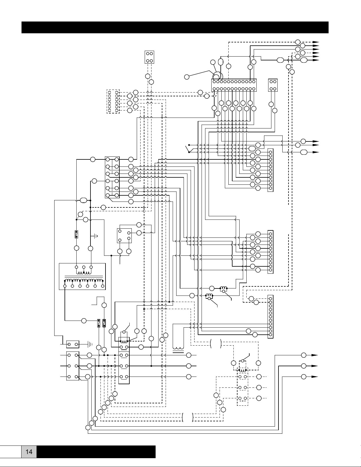
Installation, Operation, & Maintenance Manual
TRANSFORMER 2
600
480
380
230
208
0
X3
X1
MDD WIRING DIAGRAM
SLAVE SECTION
(TL)
BLK
S
BLK
BLK
U
BLK
T
BLK
129
BLK
130
BLK
(TR)
131
BLK
BLK
3
1
5
7
9
11
126
128
BLK
114
126
WHT
127
BLK
TERMINAL STRIP 5
(RDU)
FUSE 5
(2A)
FUSE 4
(2A)
BLK
132
(COM) (NO)
INTERLOCK 2
DOOR
BLK
option2
TO GND LUG
TRANSFORMER
VOLTAGE LEG OF
TO INCOMING LINE
WIRE #132 CONNECTED
IF FUSE IS MOUNTED ON TRANSFORMER
AND 127 CONNECT TO TRANSFORMER
WIRE 128 IS OMITTED AND WIRES 114
TERMINAL XF
(24 VAC)
BLK
FUSE 6
BLK
(4 A FOR 100 VA)
(6 1/4 A FOR 150 VA)
WHT
(24 RET)
GRN/YEL
BLOCK 2
TERMINAL
153
WHT
WHT
137
58
16
54
139
53
R
BLK
BLK
Q
BLK
P
56
57
55
XV. WIRING DIAGRAM
MASTER SECTION
MDD WIRING DIAGRAM
GRN/YEL
27 & 75 CONNECT TO TRANSFORMER
WIRE 28 IS OMITTED AND WIRES 14,
IF FUSE IS MOUNTED ON TRANSFORMER
TERMINAL XF
TRANSFORMER 1
0
208
GRN
GND
L1
L2
POWER INPUT
L3
POWER DISTRIBUTION
BLK
FUSE 3
BLK
(24 VAC)
X1
GND
BLOCK
28
230
75
BLK
(4 A FOR 100 VA)
WIRE #32 CONNECTED
BLK
153
BLK
14
(24 RET)
WHT
(6 1/4 A FOR 150 VA)
26
380
TO INCOMING LINE
VOLTAGE LEG OF
TRANSFORMER
31
GROUNDED
TO CHASSIS
V
BLK
W
BLK
X
BLK
BLK
BLK
R
27
26
WHT
X3
480
FUSE 2
(TR)
BLK
BLK
P
Q
TERMINAL STRIP 2
(RDU)
BLK
11
9
7
5
WHT
3
1
TERMINAL
BLOCK 1
76
CYLINDER FULL
BLK
600
BLK
32
(2A)
(2A)
FUSE 1
(TL)
15
BLK
BLK
30
29
BLK
BLK
36
M
BLK
N
BLK
O
6
5
4
3
2
1
12
10
8
6
4
2
INTERFACE 1
CYLINDER
BLUE
46
BLK
35
BLK
BLUE
BLK
BLK
ORG
WHT
BLK
ORG
WHT
WHT
ORG
WHT
WHT
2
3
4
1
RED14BLK
24
FULL
ELECTRODE
T1
L1
L2
T2
L3
T3
CONTACTOR
41
35
33
12
BLUE
17
BLUE
19
33
22
46
BLUE
21
1
(SENSOR)
V3
VARISTOR
M1
55
57
56
53
54
+
-
40
139
TERMINAL STRIP 6
24 VAC, 4 VA MAX.
WHT
BLK
76
75
42
36
38
18
20
47
DOOR
INTERLOCK 1
AIR FLOW SWITCH
(OPTION 3, SEE NOTE BELOW)
39
42
BLK
41
BLUE
(NO)
(COM)
55
WHT
WHT
2
1
BLUE
BLUE
12
45
WHT
WHT
WHT
356
4
BLK
GRN
16
11
WHT
7
RED
RED
8
10
9
GRN
BARE
8
7
WHT
56
57
BLUE
BLUE
9
11
10
12
A B
TERMINAL STRIP 1
BLK
RED
WHT
6
43
5
44
58
137
37
WHT
45
3
RED
4
ORG
5
RED
6
WHT
7
GRN
8
RED
9
RED
10
WHT
11
GRN
BLUE
2
1
RED
RED
49
48
11
10
9
4
3 5 76 8
2
1
139
TERMINAL STRIP 3
REMOTE ALARM
WHT
BOARD TERMINAL
139
54
J5
53
58
WHT
16
137
25
BLK
4
ORG
DRAIN
VALVE 1
22
ORG
47
WHT
FILL
VALVE 1
ORG
ORG
RED
38
34
3
RED
BLK
BLK
BLK
BLK
RED
BLK
25
RED
BLK
36
35
TOROID 1
A
B
C
THESE WIRES NOT
USED ON DOUBLE
CONTACTOR UNITS
POWER ELECTRODES
THESE WIRES NOT
USED ON DOUBLE
V1
VARISTOR
V2
VARISTOR
CONTACTOR UNITS
ORG
51
BLK
L1
BLK
M
N
L2
BLK
L3
O
13
WHT
20
WHT
23
ORG
19
ORG
49
RED
48
RED
34
ORG
18
BLUE
21
WHT
17
BLK
53
WHT
*
54
GRN
*
RED
RED
44
WHT
43
BLK
V4
VARISTOR
BLUE
52
G
BLK
T1
H
BLK
T2
I
POWER ELECTRODES
BLK
T3
M2
CONTACTOR
(See note below)
11
10
9
8
J3
5
4
3 76
BOARD TERMINAL
2
1
11
10
9
J1
4
3 5 76 8
BOARD TERMINAL
2
1
option 1
BLK
BLK
BLK
P
Q
R
14 www.herrmidifier-hvac.com
Herrtronic® MDD Supplement
Page 15
55
56
54
MDD WIRING DIAGRAM
57
53
SLAVE SECTION
58
137
WHT
Installation, Operation, & Maintenance Manual
(See note below)
option2
139
6
5
4
3
2
1
TERMINAL STRIP 5
(RDU)
DOOR
INTERLOCK 2
(COM) (NO)
16
BLK
WHT
127
BLK
12
11
9
10
8
7
TO GND LUG
126
153
TERMINAL
WHT
BLOCK 2
6
5
3
4
2
1
BLK
BLK
BLK
ORG
WHT
BLK
ORG
WHT
WHT
ORG
WHT
WHT
option 3
(See note below)
AIR FLOW SWITCH
(OPTIONAL)
142
141
BLUE
136
135
138
133
112
BLUE
117
118
BLUE
119
120
133
122
147
146
BLUE
121
142
BLK
141
BLUE
53
55
54
139
WHT
WHT
GRN
BLUE
2
1
BLUE
BLUE
112
145
356
4
WHT
GRN
111
7
RED
RED
108
110
109
GRN
56
57
BARE
BLUE
BLUE
8
9
11
10
12
BLK
RED
WHT
WHT
143
106
105
144
107
145
104
106
108
110
A B
TERMINAL STRIP 4
137
WHT
BLUE
103
RED
ORG
105
RED
WHT
107
GRN
RED
109
RED
WHT
111
GRN
J5
11
10
9
4
3 5 76 8
2
1
354325-001 REV D
BOARD TERMINAL
GRN/YEL
TRANSFORMER 2
P
BLK
Q
BLK
R
BLK
IF FUSE IS MOUNTED ON TRANSFORMER
AND 127 CONNECT TO TRANSFORMER
WIRE 128 IS OMITTED AND WIRES 114
TERMINAL XF
0
208
FUSE 6
X1
114
BLK
BLK
(24 RET)
BLK
WHT
(4 A FOR 100 VA)
(6 1/4 A FOR 150 VA)
126
128
(24 VAC)
CYLINDER FULL
INTERFACE 2
BLK
RED
124
X3
CYLINDER
FULL
230
380
600
480
BLK
132
(2A)
FUSE 5
(TR)
BLK
130
(2A)
FUSE 4
BLUE
146
(TL)
115
BLK
BLK
129
L1
L2
L3
BLK
135
BLK
BLK
136
S
BLK
T
BLK
U
WIRE #132 CONNECTED
BLK
TRANSFORMER
VOLTAGE LEG OF
TO INCOMING LINE
131
2
1
ELECTRODE
CONTACTOR
3
4
BLK
114
2
(SENSOR)
VARISTOR
T1
T2
T3
S1
125
BLK
104
ORG
DRAIN
VALVE 2
122
147
WHT
V7
ORG
ORG
134
138
103
RED
BLK
BLK
BLK
BLK
RED
BLK
BLK
125
135
RED
RED
136
TOROID 2
ORG
V6
VARISTOR
THESE WIRES NOT
USED ON DOUBLE
CONTACTOR UNITS
V5
VARISTOR
144
S
T
U
FILL
VALVE 2
D
E
F
POWER ELECTRODES
THESE WIRES NOT
USED ON DOUBLE
CONTACTOR UNITS
J3
113
WHT
120
119
118
121
143
ORG
151
BLK
BLK
BLK
11
WHT
10
123
ORG
9
ORG
134
ORG
BLUE
4
3 5 76 8
WHT
BOARD TERMINAL
2
117
BLK
1
J1
11
10
9
RED
4
RED
3 5 76 8
T1
T2
T3
S2
V8
VARISTOR
BOARD TERMINAL
2
1
BLUE
152
J
BLK
K
BLK
L
BLK
POWER ELECTRODES
OPTION 1. WIRE NOS. 53 AND 54 USED FOR MDDI/MDDP, PROPORTIONAL AND PROPORTIONAL & INTEGRAL
OPTION 2. WIRE NO 55 USED FOR ON/OFF CONTROL
OPTION 3. REMOVE WIRE 139 AND 39 WHEN SEPARATE AIR FLOW SWITCHES OR RDU'S ARE USED.
WHT
BLK
L1
L2
L3
CONTACTOR
Herrtronic® MDD Supplement
www.herrmidifier-hvac.com
15
Page 16

Engineered Humidification Systems
Herrmidifier
®
101 McNeill Rd. | Sanford, NC 27330
P: 800.884.0002 | F: 800.458.2379 | www.herrmidifier-hvac.com | cs@herrmidifier-hvac.com
Form No. OM-107 09/11 ©Herrmidier 2011. All Rights Reserved.
 Loading...