

Page 1

Engineered Humidification Systems
READ & SAVE THESE INSTRUCTIONS
Herrtronic® MD Series
Installation, Operation, & Maintenance
Herrmidifier® | www.herrmidifier-hvac.com
Page 2

Installation, Operation, & Maintenance Manual
TABLE OF CONTENTS
SECTION I WARRANTY
Warranty ...............................................................................................................................................3
SECTION II UNIT OPERATION
Herrtronic MD: Basic Operation ............................................................................................................ 4
Types of Control ....................................................................................................................................5
SECTION III INSTALLATION INSTRUCTIONS
Allowable Operating Conditions ............................................................................................................6
Mounting ............................................................................................................................................... 6
Plumbing ............................................................................................................................................... 6
Supply Power ........................................................................................................................................7
Steam Distributor Pipes ........................................................................................................................ 8
Steam Distributoin for Ducted Systems ................................................................................................ 9
Controls ................................................................................................................................................10
Control Circuit Connections .................................................................................................................. 10
External Off Switch ...............................................................................................................................11
Remote Alarm Output ........................................................................................................................... 12
Unit Networking ....................................................................................................................................12
SECTION IV OPERATION INSTRUCTIONS
Operating Instructions ...........................................................................................................................13
Programming ........................................................................................................................................14
Start-up with Check List ........................................................................................................................ 16
Diagnostics ...........................................................................................................................................19
System Fault Conditions ....................................................................................................................... 20
Maintenance .........................................................................................................................................20
SECTION V TROUBLESHOOTING GUIDE
General Maintenance Notes ................................................................................................................. 22
Operating The Humidier Without External Controls ............................................................................ 22
Unit Detected Faults: (Red “Service” Light On) ....................................................................................24
Non-Fault Indicated Problems ..............................................................................................................25
Troubleshooting Without Unit-Detected Faults .....................................................................................27
Output / Input of Terminal Strips and Terminal Block ............................................................................ 28
2 www.herrmidifier-hvac.com
Herrtronic® MD Series
Page 3

Installation, Operation, & Maintenance Manual
I. WARRANTY
Limited 2-Year Warranty
Seller warrants the equipment of its manufacturing to be free
from defects in workmanship and material for a period of 24
months after shipment or 24 months after initial commissioning,
whichever occurs rst. This warranty is limited, however, to the
repair or replacement of defective equipment, which is returned,
freight prepaid, to Seller’s factory.
This limited warranty does not apply to any part or component
that is damaged in transit or when handling, has been subject
to misuse, negligence or accident, has not been installed, operated or serviced according to Seller’s instructions, or has been
operated beyond the factory-rated capacity or has been altered
in any way.
Seller’s liability is limited to replacement of defective parts or
components and does not include any cost of labor (including,
but not limited to, labor required to remove and/or reinstall any
defective part) other than Trion/Herrmidier factory labor.
Each of the Herrtronic series of steam generating humidiers
contains a plastic steam generating cylinder that is to be considered a routinely disposable part to be changed at regular maintenance intervals at the user’s expense. This steam generating
cylinder is not covered by this Warranty. If, after the rst installation of your Herrtronic humidier, you feel the steam generat-
ing cylinder is not operating normally, you should contact your
Herrmidier Representative with an explanation of the problem.
However, in the continuing operation of this humidier, replace-
ments of this part are your responsibility as part of routine maintenance.
Trion/Herrmidier shall not be responsible for loss of use of
any product, loss of time, inconvenience, or damage to other
equipment, or any other indirect or consequential damage with
respect to property whether as a result of breach of warranty,
neglect, or otherwise.
THE WARRANTIES AND LIABILITIES SET FORTH ARE IN
LIEU OF ALL OTHER WARRANTIES AND LIABILITIES, EXPRESSED OR IMPLIED, IN LAW OR IN FACT, INCLUDING IMPLIED WARRANTIES OF MERCHANTABILITY AND FITNESS
FOR PARTICULAR PURPOSE.
The foregoing shall constitute the total liability of seller in the
case of defective performance of all or any of the equipment or
services provided to Buyer. Buyer agrees to accept and hereby
accepts the foregoing as the sole and exclusive remedy for any
breach or alleged breach of warranty by Seller.
Herrtronic® MD Series
www.herrmidifier-hvac.com
3
Page 4
Installation, Operation, & Maintenance Manual
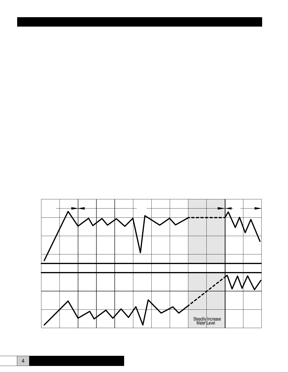
Water Level
Output
II. UNIT OPERATION
Herrtronic MD: Basic Operation
Controlled humidication requires a very precise control system. The Herrtronic MD utilizes a microprocessor to monitor
performance and maintain humidity. Further, the Herrtronic
MD evaluates the operation and alerts the operator to problem conditions and prevents undesirable operation:
1. Start-up: On initial start-up (prompted by a call-for-hu-
midity), the ll valve opens allowing water to enter the
cylinder. When the water level rises to the electrodes,
current will ow and the water will begin heating. As
the water temperature increases, its conductivity also increases, accelerating the rate of temperature increase.
When the output reaches the “capacity set point,” the ll
valve closes. The output capacity may continue to rise
slightly beyond the “capacity set point.” As the water
boils away, the water level falls. This results in a reduction in output capacity.
2. Normal Operation: Upon achieving “capacity set point,”
the system begins operation in a steady state mode.
Output capacity slowing decreases until the elapsed “cy-
cle time” opens the ll valve to replenish the water level
until the “capacity set point” output is achieved. As the
mineral concentration in the water increases, the water
conductivity also increases. Accordingly, the rate of boiling increases. Eventually, the rate of boiling reduces the
output capacity below the “low drain threshold” before
the “cycle time” initiates the ll cycle.
At this point, the drain valve opens discarding the mineral laden (highly conductive) water, replacing it with
fresh water, that lowers the mineral concentration until
the system is restored to the steady state mode.
The steady state operating mode continues with small
increases in the water level to maintain output capacity
(by exposing new electrode surface).
3. End-of-Cylinder Life: Steady State operation continues
with “ll and boil” and periodic drain cycles with ever increasing water levels. Eventually, the water level reaches the cylinder full electrode, representing the maximum
allowable water level inside the cylinder. The system
output begins to decrease since there is no new electrode surface to expose. If the system operates continuously without achieving “capacity set point,” an “end of
cylinder life” fault will be displayed.
High Drain
Threshold
Capacity
Set Point
Low Drain
Threshold
Cylinder
Full
HERRTRONIC MD: Basic Operation
1. 2.
Hours of Operation
Steadily Increase
Water Level
3.
4 www.herrmidifier-hvac.com
Herrtronic® MD Series
Page 5
Installation, Operation, & Maintenance Manual
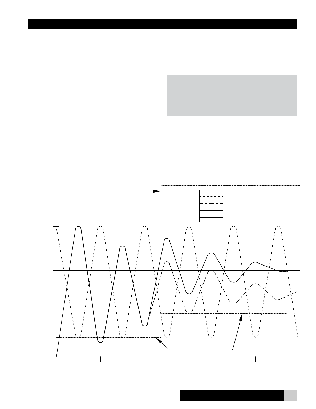
Relative Humidity %
Time
Types of Control
The Herrtronic MD System is available with (3) types of control ---(1) On/Off, (2) Proportional, (3) Proportional + Integral:
1. On/Off – Humidity is sensed by a humidistat that pro-
vides an On/Off input to the humidier. Humidity varies
above and below the setpoint based on the tolerance
and accuracy of the humidistat.
2. Proportional – A proportional controller produces a signal (ohms, volts DC, or milliamps DC) corresponding to
the difference between the control humidity and the hu-
midity setpoint. The humidier’s output increases as this
difference (and signal) increases. Humidity variations
will be smaller than with “On/Off” control and the control
humidity will be maintained within the bandwidth, tolerance, and accuracy of the controller.
Types of Control
60
3. Proportional + Integral – Over a repeating time period
the “P+I” control simply evaluates the difference between the average control humidity and the control humidity setpoint and adjusts the bandwidth to minimize
the “offset.” Optimal control is attained in most cases
with this alternative.
NOTE
If your application is unique or water is excessively
“clean” or “dirty,” consult Herrmidier for assistance in matching your humidier, water treatment,
and its control scheme to your application!
55
50
45
Offset Correction
On/Off Control
Proportional Control
Proportional + Integral Control
Set Point
40
0 5 10 15 20 25 30 35 40 45 50 55
Herrtronic® MD Series
P + I Bandwith
www.herrmidifier-hvac.com
5
Page 6
Installation, Operation, & Maintenance Manual
III. INSTALLATION INSTRUCTIONS
Allowable Operating Conditions:
Ambient Temperature: 40ºF - 120ºF (4ºC - 50ºC)
Ambient Relative Humidity: 0% to 90%
Line Voltage: -15% to +10% of Nominal
Frequency: 50/60 Hz.
Supply Water Temperature: 40ºF-100ºF (4ºC-38ºC)
Supply Water Pressure: 20-100 psig
Supply Water Conductivity:
• 70-1000 mincromho (on-off control)
• 200-1000 micromho (prop or P + I control)
(See Figure 30 & 31 on page 27 for alternative water conditions)
Maximum Duct Static Pressure: 5” MDM, 7” MDS/MDD
units
NOTE: If units are mounted in outdoor enclosures, conditions
inside enclosure must be maintained as shown above.
Mounting
The cabinet is designed to safely contain the working com-
ponents of the Herrtronic MD humidier and dissipate heat to
protect the electronics. Herrtronic MD Series electronic steam
humidiers, room distribution units, steam pipes, and any accessories should be located in a manner to facilitate routine inspection and any necessary maintenance. The unit should not
be located above (such as false ceilings) or around valuable
property, where a malfunction could cause damage. Correct
positioning of the Herrtronic MD humidier is important to allow
for proper operation and easy maintenance. Minimum clearance
around the cabinet should be maintained as follows:
Unit Clearances By Model
Unit Series MDM
5-30 Lbs.
Left 2” 2” 2”
Right 20” 20” 20”
Top 12” 12” 12”
Bottom 10” 10” 10”
MDS
10-100 Lbs.
MDD
110-250 Lbs.
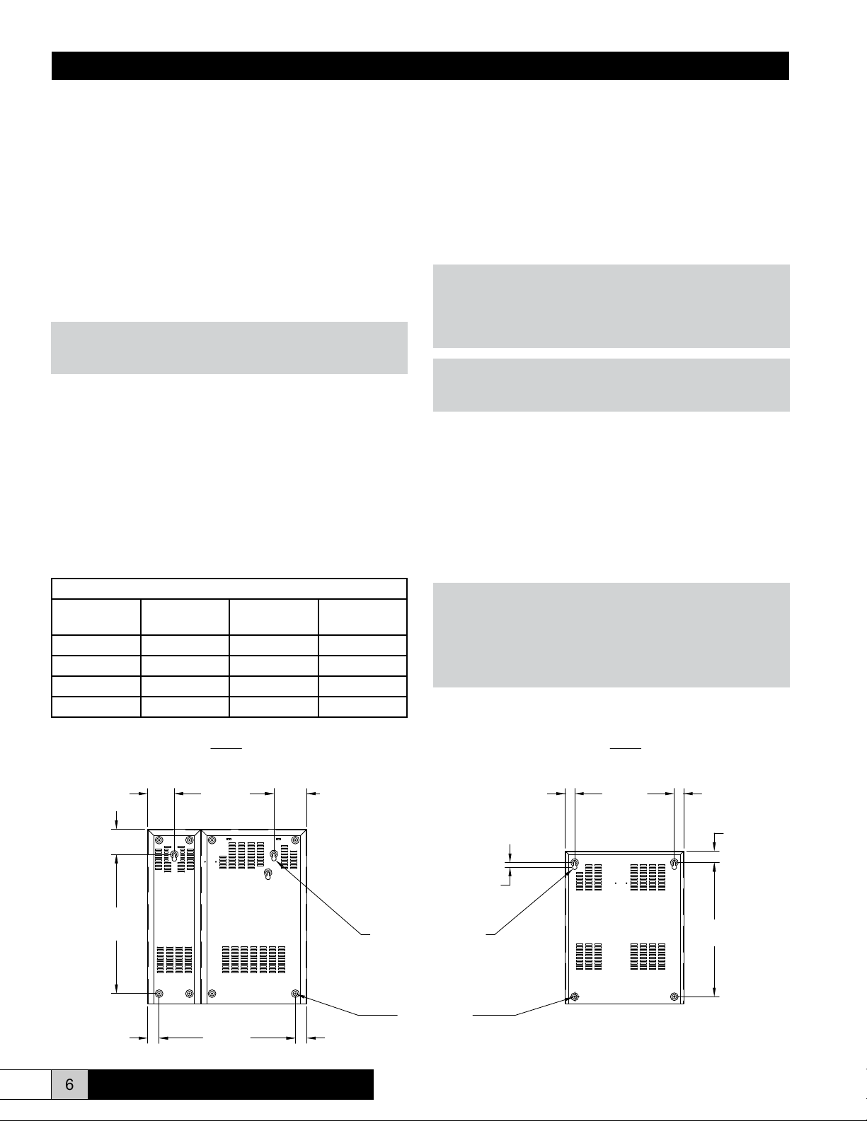
Four lag bolts, (2) 5/16” and (2) 1/4”, are supplied with the MDS
and MDM units which are designed to be secured to a wall. Install the top two lag bolts (5/16”) according to the dimensions in
Figure 1. Hang the unit on the wall, and then install the bottom
two lag bolts (1/4”) and secure all four bolts. Be sure the unit is
level and mounted directly to the wall to wood studs at least 2”
thick (or equivalent).
Operating weights are as follows:
• MDM - 82 lbs.
• MDS - 131 lbs.
• MDD - 258 lbs.
WARNING!
Do not mount any controls inside the unit or tap power from
any location in the unit, except as stated in these instructions. Do not place objects near the cabinet. Do not attach
to dry wall without studs.
NOTE
To mount the Room Distribution Unit, refer to the “supplemental” RDU Installation Instructions.
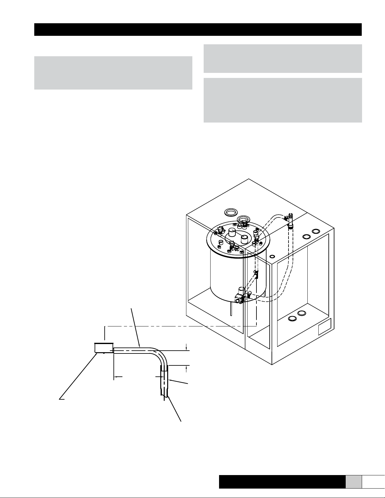
Plumbing
To make the necessary connections for water ll and drain,
the following steps are required: (refer to Figure 2 for drain
location)
1. Install an external shutoff valve between the water supply
and the humidier for ease in servicing the unit.
2. Connect water supply to 1/4” compression tting on the
bottom of the cabinet.
CAUTION!
Do not use reverse osmosis or demineralized water treatment
without rst consulting the factory. This water may not be sufciently conductive to allow proper operation. Consult factory
if water is outside the range of allowable conductivities. Do
not use hot water.
MDS MDM
10-100#
5.2516.004.25
4.00
22.38
1.81 21.89 1.81
6 www.herrmidifier-hvac.com
Figure 1
.75 Typ.
Both units
Ø .38" x Ø .75"
Keyhole Slot
Typ.
Ø .25 Typ.
5-30#
16.001.50 1.50
1.82
21.56
Herrtronic® MD Series
Page 7
Installation, Operation, & Maintenance Manual
3. Connect the ¾” tube from the accessory pack to the drain
reservoir. Cut hose to necessary length.
WARNING!
Be sure that the ¾” drain tube is not kinked or bent in a man-
ner to prevent free owing drainage from the drain reservoir
to the drain pipe.
4. Insert the other end of the tube into a minimum 6” length of
1 ¼” minimum I.D. copper line. The balance of the drain
line should be 1” I.D. minimum with a minimum 1/8” per foot
slope. (See Figure 2)
Figure 2
WARNING!
If the drain line is exposed, it is recommended that it be insulated for safety. Do not use PVC drain line unless “Drain
Tempering” is enabled (see page 16-17).
NOTE
Inlet water pressure must be in the range of 20-100 psig.
Consult the factory if you are outside this range. Softened water may be used but requires that the low drain threshold be
adjusted (refer to Fig. 30 page 27). Drain water can be tempered to lower its temperature (refer to page 16).
3/4" MIN. I.D./1" MAX O.D.
FLEXIBLE DRAIN CONNECTION
RECOMMENDED
DRAIN RESEVOIR
4" RECOMMENDED
8"
6" MIN. LENGTH OF 1-1/4" MIN. I.D.
COPPER LINE. IF PVC IS USED, LOCAL
CODES REQUIRE A LOWER TEMPERATURE
DRAIN WATER, ADD DRAIN TEMPERING.
BALANCE OF DRAIN LINE TO BE 1" MIN. I.D.
WITH A MINIMUM PITCH OF 1/8" PER 12" OF RUN
Herrtronic® MD Series
www.herrmidifier-hvac.com
7
Page 8
Installation, Operation, & Maintenance Manual
Supply Power (See Electrical Characteristics Table Below)
1. Ensure that adequate service is available to carry 125% of
rated amp level.
2. Field wiring of the main power supply is connected directly
to the contactor (single contactor units) or to a power distribution block (multiple contactor units) located in the electrical compartment. A ground lug is provided for the ground
wire.
3. Install external overcurrent protection and provide wiring in
accordance with the NEC, state and local code.
4. Power supply must be “clean”; free of spikes, surges and
sags; -15% to +10% of Nominal. Ground should be a true
earth ground.
Steam Distribution for Ducted Systems
Each steam cylinder requires at least one outlet for steam via
a duct distributor or Room Distribution Unit. (See RDU supplement for Room Distribution Unit)
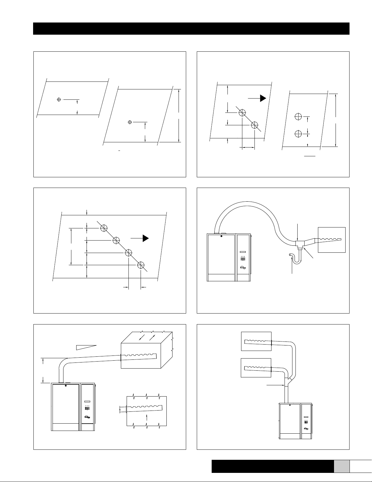
Steam Distributor Pipes
Herrmidier supplies stainless steel duct distributor pipe(s) for
use in injecting pure steam into ducts. Refer to Figure 3, 4, or 5
for proper placement. A minimum of 3’ clearance downstream
is required for most applications. However, differing pyschrometric conditions may require a greater or lesser steam absorption distance. Consult the factory if you have any questions or
need to exchange your standard distribution system for a rapid
absorption CS-Series Distribution system.
NOTE
• The rubber steam hose carries steam to the distributor pipe
and condensate back to the unit. It must have an 8% (1”
per foot) pitch back to the unit. Support the steam hose so
it will maintain the proper pitch when in operation or at rest.
• If any low spots are in the steam line or the unit is mounted
higher than the distribution system, spitting may occur from
the steam distribution pipes. A condensate separator (EST-
250) is available from the factory. (See Fig. 6)
• If you must split the discharge of one steam outlet into two
ducts with the same static pressure, a “Y” connector (EST-
255) is available from the factory. The length of steam hose
after the “Y” connector must be the same for equal distribution of steam. (See Fig. 8)
• Mount the unit as close to the distribution pipe as possible.
Use 1 ½” Type L insulated copper pipe whenever the length
of run exceeds 20 feet. Do not exceed a 30 foot run as the
capacity of the unit will be decreased by as much as 15%
and the increased static pressure could cause problems
with the ll system.
• Maximum duct static pressure: 5” MDM units, 7” MDS and
MDD units.
• Internal duct insulation should be removed in the “bulk
evaporation” zone (Consult factory representative).
• Steam holes in the distribution pipe are located 2” from
mounting plate and designed for a maximum duct wall
thickness of 1”. Consult factory if special hole locations
are required.
• Do not mount the standard distribution pipe in a vertical
downow or vertical position in a horizontal ow system.
Special pipes are available, consult the factory.
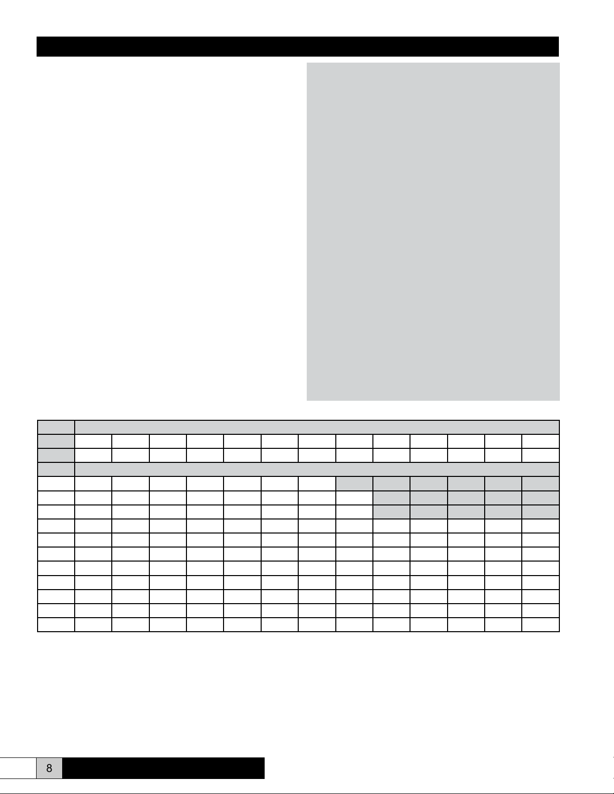
Steam Output
Lb/hr 5 10 15 20 25 30 40 50 60 70 80 90 100
Kg/hr 2.3 4.5 6.8 9.1 11.4 13.6 18.2 22.7 27.2 31.8 36.3 40.9 45.4
Voltage Electrode Current (amps)
208/1
240/1
277/1
208/3
240/3
380/3
440/3
460/3
480/3
575/3
600/3
KW = .333 X Lbs/Hr
Amps(1Ph) = KW X 1000 / (Voltage)
Amps(3Ph) = KW X 1000 / (Voltage X 1.732)
Min. Circuit Ampacity = 1.25 X Rated Electrode Current (Note: with RDU add .5 Amps @ 208/240 Volts or add .25 Amps @ 480 Volts)
Minimum Circuit Ampacity determines wire size (AWG)
8.0A 16.0A 24.0A 32.0A 40.0A 48.0A 64.0A
6.9A 13.9A 20.8A 27.8A 34.7A 41.6A 55.5A 69.4A
6.0A 12.0A 18.0A 24.0A 30.1A 36.1A 48.1A 60.1A
4.6A 9.2A 13.9A 18.5A 23.1A 27.7A 37.0A 46.2A 55.5A 64.7A 73.9A 83.2A 92.4A
4.0A 8.0A 12.0A 16.0A 20.0A 24.0A 32.0A 40.1A 48.1A 56.1A 64.1A 72.1A 80.1A
2.5A 5.1A 7.6A 10.1A 12.6A 15.2A 20.2A 25.3A 30.4A 35.4A 40.5A 45.5A 50.6A
2.2A 4.4A 6.6A 8.7A 10.9A 13.1A 17.5A 21.8A 26.2A 30.6A 35.0A 39.3A 43.7A
2.1A 4.2A 6.3A 8.4A 10.4A 12.5A 16.7A 20.9A 25.1A 29.3A 33.4A 37.6A 41.8A
2.0A 4.0A 6.0A 8.0A 10.0A 12.0A 16.0A 20.0A 24.0A 28.0A 32.0A 36.0A 40.1A
1.7A 3.3A 5.0A 6.7A 8.4A 10.0A 13.4A 16.7A 20.1A 23.4A 26.7A 30.1A 33.4A
1.6A 3.2A 4.8A 6.4A 8.0A 9.6A 12.8A 16.0A 19.2A 22.4A 25.6A 28.8A 32.0A
8 www.herrmidifier-hvac.com
Herrtronic® MD Series
Page 9
Installation, Operation, & Maintenance Manual
Steam Distribution for Ducted Systems
DUCT HEIGHT
10" - 16"
(254MM) - (406MM)
(76mm)
3"
DUCT HEIGHT > 16"
(406mm)
DUCT HEIGHT
10" - 16"
(254MM) - (406MM)
AIR
6.5" (165mm)
FLOW
H
3.00" (76mm)
8.00
(203mm)
H
-5" (127mm)
h=
2
h
FIGURE 3 - SINGLE DISTRIBUTOR PIPE FIGURE 4 - DUAL DISTRIBUTION PIPES
DUCT HEIGHT>16"
(406MM)
6.5" (165mm)
h/3
AIR
FLOW
DUCT HEIGHT > 16"
(406mm)
h
3"
(76mm)
EST-250
SEPARATOR
(H-15)
2
h (in) = 6 +
CONDENSATE
H
h
h/3
h/3
3.0"
FIGURE 5 - MULTIPLE DISTRIBUTION PIPES
MIN. 8% (1" PER FOOT)
10" MIN.
(254mm)
NO SAGS
ALLOWED
CYL FULL
FAULTPOWER
ON/OFF
BACK
ENTER
FAULTS
HERRTRONIC MD
STEAM DISCHARGE MUST ALWAYS
BE FROM THE TOP OF DISTRIBUTOR
FIGURE 7 - STANDARD DUCT DISTRIBUTION
8.00
(typ.)
HORIZONTAL DUCT
VERTICAL DUCT
CYL FULL
FAULTPOWER
ON/OFF
BACK
ENTER
FAULTS
HERRTRONIC MD
½" TUBE
TO NEAREST
OPEN GRAVITY DRAIN
FIGURE 6 - INSTALLATIONS WITH UNAVOIDABLE LOW SPOT
EST-255
"Y" CONNECTOR
POWER FAULT
CYL FULL
BACK
ON/OFF
ENTER
FAULTS
HERRTRONIC MD
FIGURE 8 - TWO SEPARATE DUCTS
AT LOWEST
POINT
Herrtronic® MD Series
www.herrmidifier-hvac.com
9
Page 10
Installation, Operation, & Maintenance Manual
Controls
The Herrtronic MD Series Humidier has the capability to utilize
one of three types of control schemes.
1. On/Off
2. Proportional
3. Proportional + Integral
Controls may be supplied by the factory or others. The following
information applies to all controls factory supplied or furnished
by others. All external electrical control circuits are to be connected to the unit using the twelve pole terminal strip located
in the electrical compartment. The terminal strip is accessed
through the side electrical compartment door. Field wiring from
humidistat to humidier and between safety devices, such as
high limit humidistat and air proving switches, should be 18
AWG stranded or 20 AWG solid wire. If conduit is not used with
the controls wiring, install the black plastic ngered bushing (in
accessory pack) and completely seal with RTV silicone.
Wall devices should be mounted at a height similar to that of a
typical thermostat and should be located in an area that will pro-
vide good representation of the overall space being humidied.
Do not mount wall devices directly in the air stream of a supply
grille or room distribution unit.
Duct control devices should be mounted in a location where the
humidity and temperature are uniform, usually the return duct.
Do not mount in front of the steam distributor or in a mixing,
turbulent, or isolated area.
Duct high limit devices should be mounted downstream of the
steam distributors-far enough that under normal conditions in
the air stream, the steam has been completely absorbed, typically 10 ft. The device should be located such that it can sense
humidied air as it approaches saturation. Do not mount in dead
air spaces such as inside of corners or erroneous operation may
result.
Air proving devices should be mounted so that they sense air
ow (or the absence of it). Wire the device so that it closes when
air ow is present and will open when there is no air ow. The
purpose of the device is to prove that air ow is present before
steam is distributed into the duct.
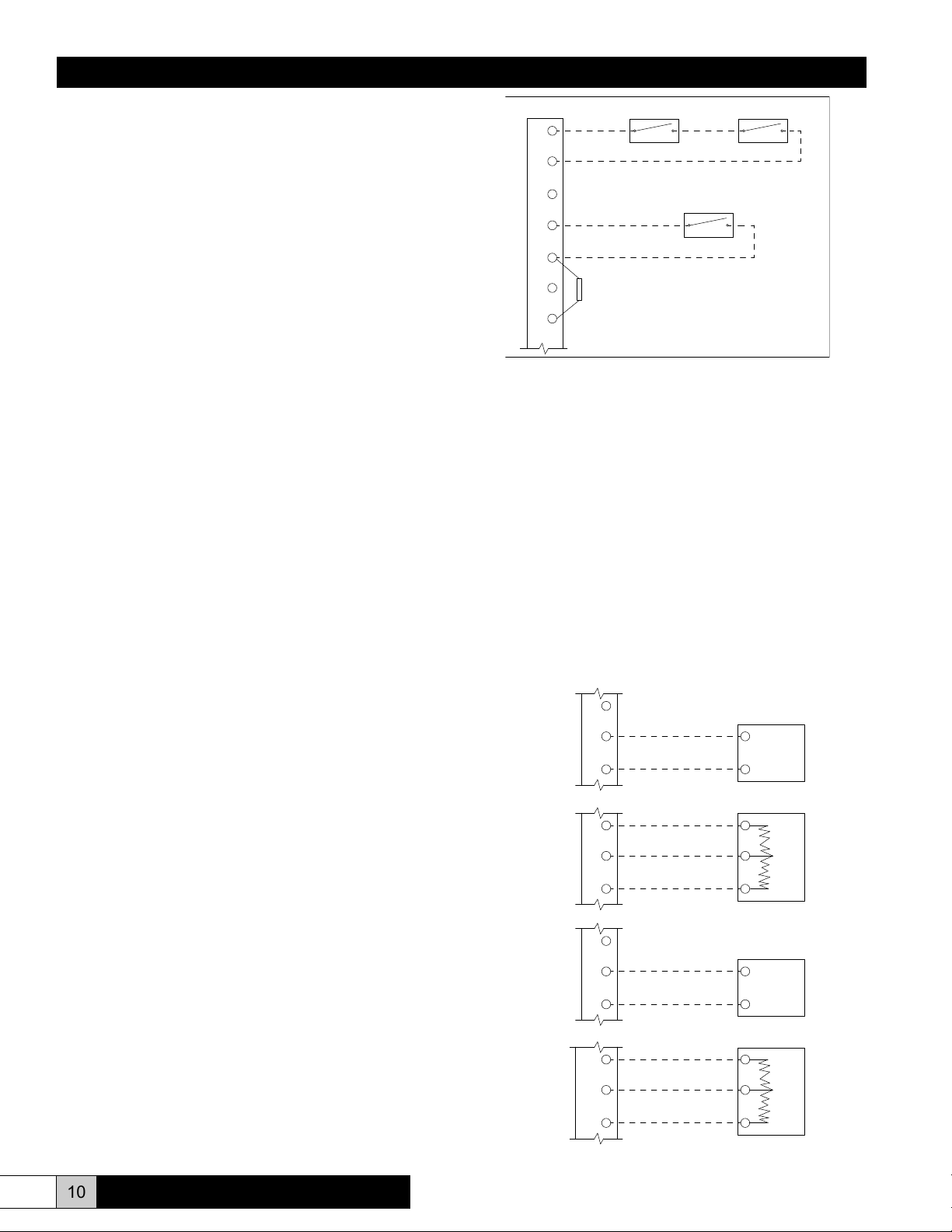
The following information and diagrams are shown for each control scheme. Please refer to the control scheme that your humidier was set up for and follow the diagram for control circuit connections. The factory-set control type and signal are indicated
on a label adjacent to the controls terminal strip.
Air Flow Switch High Limit Stat
1
2
3
Control Humidistat
4
5
68.1 k Resistor
6
Ω
7
See Note Pg. 28
Mode 2 - Proportional Operation
1. If two position airow and/or high-limit humidistat is used
wire as shown in Figure 9.
2. Control Input - Interpreted by the humidier as a demand of
output signal. Input device should be linear. Unit can accept
any VDC or mADC signal within a range of 0-20 VDC or
mADC (See Fig. 10). Unit may also accept a resistive signal
0-135 ohms (See Fig. 11).
3. Limit Input - Unit may accept any modulating input within
the same ranges as the control inputs listed above.
a. Proportional VDC or mADC (See Fig. 12)
b. Resistive (See Fig. 13)
Additionally, a P + I sensor may be used as a limit
input.
c. VDC (See Fig. 16)
d. mADC (See Fig. 17)
_
4
FIGURE 10
5
+
_
4
5
OUT
FIGURE 11
6
+
FIGURE 9
VDC or
mADC
Signal
W
R
B
Control Circuit Connections
Mode 1 - ON/OFF Operation
1. Control Input - Unit will operate with any two position device
(See Fig. 9). Demand for humidity will close the contact.
2. Limit Input - Unit will operate with any two position device
(See Fig. 9). The humidistat contact will open on humidity
rise.
10 www.herrmidifier-hvac.com
FIGURE 12
FIGURE 13
8
9
8
9
10
_
VDC or
mADC
Signal
+
_
W
OUT
+
R
B
Herrtronic® MD Series
Page 11
Installation, Operation, & Maintenance Manual
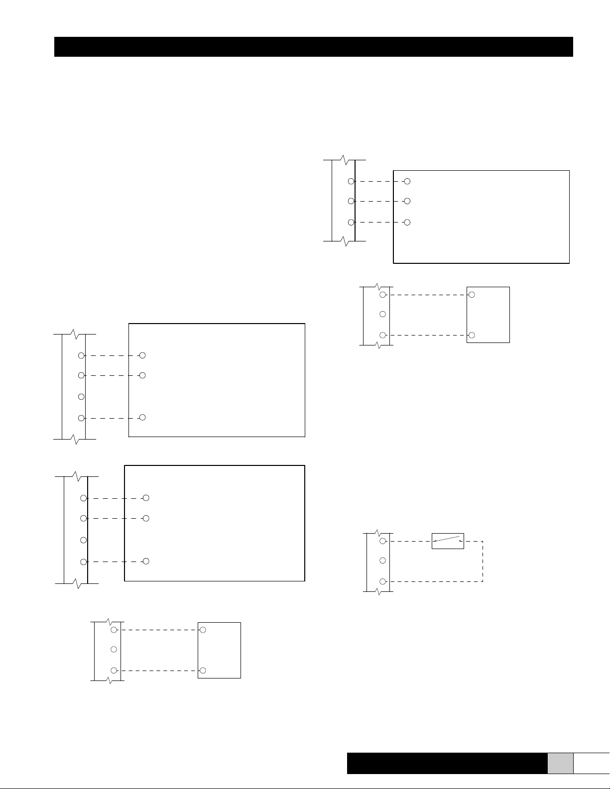
Mode 3. (Proportional + Integral)
1. If two position airow and/or high-limit humidistat is used,
wire as shown in Figure 9, page 10.
2. Control Input - Unit will accept any sensor input that pro-
vides a VDC (See Fig. 14A, wall or Fig. 14B, duct) or nmADC (See Fig. 15) signal within a range of 0-20 VDC or
mADC that is proportional to the humidity level in the air.
The sensor may be direct or indirect acting but must not
have an impedance greater than 500 ohms, and should be
linear. Example - A direct acting 2 - 10 VDC wall sensor will
send a 2 VDC signal if the R.H. level in the space is 10%; it
would send a 10 VDC signal if the R.H. level is 90%. The
humidier receives this input and compares it to the control
setpoint that has been programmed into the unit. The microprocessor modulates the output capacity of steam. The
adjustable integration period will review performance over
the given time and will make tuning adjustments by shifting
the proportional bandwidth to correct for over or under hu-
midication offsets automatically.
3. Limit Input - Unit can accept any sensor input as specied
above.
a. VDC sensor input (See Fig.16).
b. mADC sensor input (See Fig. 17).
7
8
9
FIGURE 16
PWR
GND
RH (0 -10 vdc Output)
HED3VSX
Duct
Sensor
(EST-1600)
4
5
6
7
FIGURE 14A
4
5
6
7
GND
RH (0-10 vdc Output)
PWR
GND
RH (0-10 vdc Output)
PWR
HEW3VSX
Wall
Sensor
(EST-1601)
HED3VSX
Duct
Sensor
(EST-1600)
External Off Switch
Should a eld installed remote off switch be required, follow
the wiring diagram below (See Fig. 18). Be sure to remove the
jumper wire between poles 1 and 3 on “Controls Terminal Strip.”
The remote off switch is to be wired between poles 1 and 3. This
switch will override the unit on/off switch to turn the unit off only,
it will not restart the unit. The unit must be turn back on by the
unit on/off switch.
Herrtronic® MD Series
www.herrmidifier-hvac.com
11
Page 12

Installation, Operation, & Maintenance Manual
Remote Alarm
The Herrtronic MD Humidier is equipped with a remote alarm
output. It is a triac output that may be used to energize an external relay or buzzer to indicate an alarm condition is present. The
alarm output is activated whenever an indicating fault condition
exists. When units are networked together, the master’s alarm
contacts will close if a fault occurs at either the master or one of
the slave units. The contacts are connected at poles 1 and 2 of
the remote alarm terminal strip 3.
In order to use the remote alarm output with a Building Management System, the remote alarm output must be used to energize
a mechanical relay. The contacts of the external relay may then
be wired to an input on the BMS to indicate if an alarm condition
is present. The remote alarm output may not be used like a dry
contact to a BMS.
Do not exceed the contact specications!
Contact rating:
• 24 VAC - 3.0 A
• 24 VDC - 2.1 A
Unit Networking
When networking units together in a master/slave conguration, be sure to maintain polarity between poles 11 and 12 on
all units. Units are to be wired as a parallel circuit. More than
one branch is allowable so that the master unit can be centrally
located (See Fig. 19). A maximum of 29 slave PC boards (29
MDS or MDM units or 14 MDD units) may be congured as a
network. Included in each installation pack is a 120 ohm resistor.
This resistor should be inserted into R28 on the microprocessor
board (see Fig. 32) on the appropriate end units of the chain.
(Refer to Fig. 19)
12 www.herrmidifier-hvac.com
Herrtronic® MD Series
Page 13

Installation, Operation, & Maintenance Manual
IV. OPERATING INSTRUCTIONS
Your unit has been pre-set for 1 of 3 control modes:
1. On/Off
2. Proportional
3. Proportional and Integral
With each control mode, there is a specic set of operating parameters and setpoints that apply. All of the setpoints have been preset
at the factory to simplify the start-up procedure. The following table identies the parameters, setpoints and preset values that apply
to each mode. Below the table is a more detailed description of the setpoint parameters. All setpoints have pre-set default values to
simplify programming. Instructions for adjustment follow.
Setpoint Parameters
Control Mode
1 2 3
Menu to
Adjust
Adjust Setpoint Range
MDM
Preset Values
MDS/MDD
Preset Values
Control Setpoint X 2 20-98% 35% 35%
Limit Setpoint (Note 3) X X 2 20-99% 75% 75%
High Humidity Alarm X 2 20-100% 99% 99%
Low Humidity Alarm X 2 10-98% 10% 10%
Capacity Setpoint X X X 2 10-100% 100% 100%
Auto Drain X X X 2 0-99 Days 7 Days 7 Days
Low Drain Threshold X X X 2 50-100% 85% 80%
Steam Output Rating X X X 3 0-999 lbs/hr. 5-30 lbs/hr. 10-100 lbs/hr.
Electrode Current Rating X X X 3 0-999 Amps As required As required
High Drain Threshold X X X 3 100-120% 110% 110%
Cycle Time X X X 3 30-300 Sec. 75 /(90) See note 1 130 /(150) See note 2
Proportioning Band X 3 +/- 2 to 15% +/- 10% +/- 10%
Integration Period X 3 0-60 Min. 30 Min. 30 Min.
Throttling Range (Note 3) X X 3 0-25% 10% 10%
Unit Address X X X 3 0-99 01 01 MDS (00, 01 MDD)
Low Drain Limit X X X 3 25-75% 50% 50%
Manual Drain X X X 5 Active/Inactive Active Active
Leakage Protection X X X 5 On/Off Off Off
End of Cyl. Life Setpoint X X X 5 1-500 hrs. 6 hrs. 6hrs.
Electrode Run Time X X X 5 0-999,999 hrs. 0 0
Limit Input (Note 3) X X 5 Enable / Disable Enable Enable
Control Input X X X 5 Enable / Disable Enable Enable
Drain Tempering X X X 5 Active/Inactive Inactive Inactive
Notes:
1. On units where voltage is 380 VAC or greater, the cycle time is 75 seconds. On units where voltage is 240 VAC or less, the cycle time is 90 seconds.
2. On units where voltage is 380 VAC or greater, the cycle time is 130 seconds. On units where voltage is 240 VAC or less, the cycle time is 150 seconds.
3. If a unit is ordered with the modulating high limit, the Limit Input will be ENABLED. If an “On/Off” type or no high limit is used, the Limit Input and Throttling Range
screens will have been eliminated.
Parameter Denitions: All Control Modes
• Output Rating - Unit design capacity (lbs/hr).
• Electrode Rating - Current rating that corresponds to unit design capacity.
• Capacity Rating - Output capacity as a % of the output rating.
• Low Drain Threshold - Minimum output capacity % that initiates a drain cycle.
• High Drain Threshold - Maximum output capacity % that initiates a drain cycle.
• Auto Drain - Time in days between system shutdown and cylinder drain.
• Manual Drain - Operator activated cylinder drain
• Drain Tempering - Allows mixing of cool inlet water with drain water for tempering
• Cycle Time - Time in seconds between ll cycles.
• Unit Address -In network installation; “master unit” is “00”, slaves “01” to “99”.
• Leakage Protection - Electrically disconnect electrodes during drain cycle.
• Electrode Run Time - Hours of cylinder operation.
• Control Input - Space condition humidity input device.
• End of CYL Life Setpoint - Unit has not achieved desired output within specied
time.
Specic Control Modes (See Chart)
• Control Setpoint - Desired % RH
• Limit Input - Modulating high limit from a controller or sensor
• Limit Setpoint - Maximum allowable % RH limit
• Low Humidity Alarm - Indication of control humidity level below alarm setpoint.
• High Humidity Alarm - Indication of control humidity level exceeding alarm set-
point.
• Proportioning Band - Humidity span around control setpoint where modulation
occurs.
• Integration Period - Length of time period for %RH evaluation and adjustment.
• Throttling Range - Humidity range below limit setpoint where modulation occurs.
All setpoints have pre-set default values to simplify programming -Instructions for
adjustment follow.
Herrtronic® MD Series
www.herrmidifier-hvac.com
13
Page 14

Installation, Operation, & Maintenance Manual
SETPOINT 35%
Programming
When power is initially applied (i.e. close the disconnect), the
liquid crystal display (LCD) will become active (without user action). A “signature” screen will appear:
HERRMIDIFIER INC.
HERR 002 VER 5.X
“Ver 5.X” denotes the program level of the microprocessor. The
specic “Ver 5.X” level should be included in any inquiry to a
Herrmidier representative or the factory. After a brief pause, the
‘”Main Menu” will appear:
SYSTEM OFF 000% X 01
MENU Y
The contents of the display provide the following
information:
“System Off” - The “ON/OFF” button is in the “OFF” position.
“000%” - Output capacity in % “0%” = 0 lbs /hr. Range is 0-100%
“X” - Control Mode:
1. On/Off
2. Proportional
3. Proportional + Integral
“01” - Unit Address
“Menu Y”- Designates program MENU:
Menu 1 - Status Items (non-adjustable)
Menu 2 - Setpoint Adjust (non-secured)
Menu 3 - Setpoint Adjust (secured by “password”)
Menu 4 - Network Communication
Menu 5 - Maintenance Adjust (infrequently used options)
Prior to start-up, the operator should review and/or adjust all
setpoints and, if needed, establish the network conguration.
Programming is accomplished as follows:
1. Press the “up” arrow for Menu 2. The LCD screen will read:
2. Press “Enter” to initiate the Menu program. The LCD will
read:
CONTROL 3 01
3. Press the “up” or “down” arrow button to increase or decrease the pre-programmed setting as desired.
4. Press “Enter” to register the setpoint and move to the next
setpoint.
5. Repeat steps “3” and “4” until all of that Menu’s setpoints
are registered.
6. Press “Back” to return to the MAIN MENU. (Menu 1)
7. Press the “up” arrow for Menu 3. The LCD will read:
SYSTEM OFF 000% 3 01
MENU 3
8. Press “Enter”. The LCD will read:
ENTER PASSWORD
NOTE!
Menu 3 is password secured. The setpoints in this menu are
protected from routine adjustment. The unit is shipped new
with three presses of the “Enter” key as the password.
9. To set a new password, six keystrokes are required. The
rst three keystrokes tell the unit that a new password is
being set. The last three keystrokes are the actual password. To set a new password, press “On/Off”, “up” arrow,
“Enter” and any (3) additional keystrokes - i.e. “up” arrow,
“down” arrow, “Back”. These last (3) keystrokes become
your “password.” Any subsequent revisions to Menu 3 setpoints will require use of this three keystroke “password.”
SYSTEM OFF 000% 3 01
MENU 2
NOTE!
Control Mode may be: (1), (2), or (3). This example pertains
to mode (3). In control modes (1) and (2), not all setpoints will
appear (The table on page 13 identies parameters visible in
each mode).
14 www.herrmidifier-hvac.com
NOTE!
If the wrong password is entered, the LCD will read:
INCORRECT
PASSWORD
Refer to step 9. The last (3) keystrokes become the new password.
Herrtronic® MD Series
Page 15

Installation, Operation, & Maintenance Manual
10. After establishing the “password”, repeat steps 3 through 5
to program Menu 3. Press “Back” to return to MAIN MENU.
(Menu 1)
11. Press “up” arrow for Menu 5. The LCD will read:
16. Press “up arrow” if you would like to access slave 2 and “up
arrow” again for slave 3, etc.
17. From the screen described in step 15, press “Enter” to access Slave 01. The LCD will read:
SYSTEM OFF 000% 3 01
MENU 5
12. Repeat steps 3 and 4 to complete Menu 5. The press “Back”
to return to the MAIN MENU (Menu 1)
NOTE!
Programming of the setpoints for the unit is now complete. If
there are multiple Herrtronic MD’s networked together OR you
are programming a MDD (110-250 lbs/hr.) unit, continue to
step 13. Otherwise proceed to STARTUP with CHECK LIST,
page 16.
Access Menu 4 for MDD Models only (2 tanks) or Networked
Units. This allows you to program the slave circuit board.
NOTE!
The address in the below screen is now 00. This allows the
‘Master” unit access to any “Slave” in the “Network.” Only one
Master unit “00” per Network can be used.
13. Press the “up” arrow for Menu 4. The LCD screen will read:
SYSTEM OFF 000% 3 00
MENU 4
SYSTEM OFF 000% 2 01
MENU 1
NOTE!
On MDD units, the address of the slave unit is factory set as
01. To reprogram the Slave, repeat steps 1 through 12 described on previous page.
NOTE!
If communications are not successful, the LCD will read:
NO REPLY ENTER TRY
AGAIN BACK TO EXIT
Possible sources for failed communication attempt:
A. Chosen Slave does not exist.
B. Slave unit does not have power connected.
C. Faulty communications wiring
1. Improper polarity of RS-485 (Controls Terminal
Strip Poles 11 & 12).
2. Resistor required to signify the beginning and end
of the “Network” is not installed correctly. On individual MDD units, these resistors are not necessary. See “Installation/Networking” section for clari-
cation.
D. It is possible for high levels of Electro-Magnetic Interfer-
ence (EMI) to impede communications between units.
Press “Enter” to try communications again, or “Back” to
return to “Master” units’ Main Menu.
14. Press “Enter”. The LCD will read:
POLLING SLAVE PRESS
BACK FOR MASTER MENU
This screen will appear only when power has been initially applied or reapplied. Wait about (5) minutes to allow the microprocessor to “Poll” the network.
15. After returning to the screen described in step 13, press
“Enter”. The LCD will read:
ENTER SLAVE
NUMBER 01
Herrtronic® MD Series
18. To return to “Master” unit (unit address 00) press the “up”
arrow (3) times. The LCD will read:
SYSTEM OFF 000% 2 01
MENU 4
19. Press “Enter”. The LCD will read:
LEAVING SLAVE PRESS
BACK FOR MASTER MENU
20. Press “Back” and return to “Master” unit (unit address 00)
Main Menu.
21. To program additional slaves, repeat steps 13-20. Programming is complete. Proceed with START- UP section.
www.herrmidifier-hvac.com
15
Page 16

Installation, Operation, & Maintenance Manual
Start-up with Check List
After all programming is completed (and the total installation is
complete), the Herrtronic MD system is ready to start. At the
end of START-UP section is a CHECK-LIST. The CHECK-LIST
is intended to highlight critical installation points. A poor installa-
tion frequently results in start-up difculties, and always results
in less than ideal operation of the humidier.
IMPORTANT- Before any Herrmidier representative or the
factory is contacted with a start-up problem; please have the
checklist completed as far as possible.
1. Set all controls to their lowest setting (control and high limit
if applicable). In systems using distributor pipes, make sure
the fan is operating. By placing the controls at their lowest
setting and turning the unit “ON” at the “ON/OFF” button,
the unit should not try to initiate production of steam. On
MDD units it is necessary to turn the Slave “on” through the
communications, Menu 4.
Find the lowest setting in each Control Mode as follows:
• Mode 1 (On-Off)-Turn the dial to the OFF position or
its lowest setting.
• Mode 2 (Proportional) - Set the controller to send the
lowest signal in the range (i.e. 4 mA in a direct 4-20
mA range).
• Mode 3 (P + I) - Set “Control Setpoint” through Menu
2 at least 11% below the “Control RH” displayed in
Menu 1.
2. Set high limit to its highest setting (all control modes).
3. Set CONTROL input to get the Herrtronic MD to attempt
100% of capacity as follows:
• Mode 1 (On-Off) - An audible “click” will be heard
when the humidistat is asking for full output.
• Mode 2 (Proportional) - Set controller to send
Herrtronic MD a full signal (i.e. 20 mA in a direct 4-20
mA output range).
• Mode 3 (P + I) – Set “Control Setpoint” through Menu
2 20% Above “Control RH” displayed in Menu 1.
4. TURN UNIT ”ON”. (ON MDD UNITS, BOTH MASTER AND
SLAVE BOARDS MUST BE TURNED “ON”.) Slave units
can be turned on via the Master board through communications or directly from the slave circuit board. Once the unit
gets the signal to run and unit is turned “On”, the contactor
will pull in within 5 seconds, followed by the ll valve being energized. The unit will attempt to ll to FULL OUTPUT
(100%) or CYLINDER FULL. If the unit fails to reach 75%
of capacity on the initial ll (as shown by CYLINDER FULL
light illuminated and <75% Output), you should use the
jumper wires enclosed in the accessory envelope and arrange them as shown on the diagrams on Figure 28, page
21. Be sure to disconnect power rst and re-tighten each of
the electrode knobs.
NOTE!
THIS WILL NOT BE POSSIBLE ON UNITS WHICH ALREADY HAVE POWER TO EACH ELECTRODE OR ANY
MDM. Before restarting the unit, drain half the water from the
cylinder using “Manual Drain” found in Menu 5.
5. If low conductivity water is being supplied, as indicated by
a low percentage of output (70% and under) and the CYL-
INDER FULL light is illuminated, you may want to articially
increase the output. This is accomplished by the following
procedure:
• Drain 1/2 the water from the tank using the manual
drain option in Menu 5.
• Add 1 Alka-Seltzer tablet
• Restart
• Repeat if needed
6. Fill System (Fig. 20) Check Points
• No leaks in system
• Virtually all the water entering the FILL TEE should
be going down the FILL TUBE as opposed to the
OVERFLOW TUBE. A slight adjustment may be
needed to the Metering Screw (Fig. 21) if water supply pressure is too high. Turn the screw clockwise to
close, or counter clockwise to open.
Figure 20
7. If you need to “TEMPER” the drain water because of local codes or low temperature drain piping is used, activate
“DRAIN TEMPERING” (Menu 5)
NOTE!
The drain water is TEMPERED or COOLED by the addition of
fresh water while the drain solenoid is open. The proper rate
of fresh water will cool the drain water and still allow the hu-
midier to drain freely. Use the ll valve adjusting screw (Fig.
21) to regulate the owrate of the cool inlet water. The amount
of tempering will depend on incoming temperature and pressure of the water supply.
8. Once the water is boiling and steam is being produced,
check the following:
• No leaks in the steam distribution lines or connections.
• The steam has a clear path from the cylinder to its
distribution points. Any low spots in the steam distribution line must be trapped. (See Fig. 6)
9. Unit needs to drain hot water to check proper drain line installation. Unit may be draining through normal operation,
but if not, initiate a drain through the MANUAL DRAIN in
16 www.herrmidifier-hvac.com
Herrtronic® MD Series
Page 17

Installation, Operation, & Maintenance Manual
Menu 5. Once hot water is being drained, check the following:
• Steam condensing on the bottom of the cabinet.
Correct by lowering the drain line or adding DRAIN
TEMPERING.
• Flash steam entering the steam cylinder compartment due to inadequate drain line.
• Flash steam entering the electrical compartment if
the knockout for the control wires isn’t sealed. This
should be sealed even if there doesn’t appear to be
any steam entering into the compartment. If conduit
is not used with the controls wiring, install black plas-
tic ngered bushing and completely seal with RTV
Silicone.
• Water must drain from unit freely. If there are restrictions in the drain line, it will send hot water/steam up
into the CABINET DRAIN and/or the OVERFLOW
TUBE which will pool inside the cabinet and could
leak out of the unit onto the oor.
START-UP IS COMPLETED. MAKE SURE CONTROLLING
DEVICES ARE SET FOR DESIGNED CONDITIONS. PROCEED TO AND COMPLETE CHECK-LIST. AFTER INITIAL
WARM UP, SHUT UNIT DOWN, TURN OFF MAIN POWER
AND RECHECK TIGHTNESS OF POWER CONNECTIONS
WHILE UNIT IS WARM (TORQUE TO 15-20 in-lbs.).
Figure 21
Herrtronic® MD Series
www.herrmidifier-hvac.com
17
Page 18

Installation, Operation, & Maintenance Manual
1. MATCHES DATA PLATE
2. IS PROPERLY GROUNDED
3. CAN CARRY AT LEAST 125%
OF RATE AMP DRAW
4. DISCONNECT SUPPLIED BY
OTHERS.
MAKE SURE ALL HIGH VOLTAGE
ARE TIGHT.
ELECTRICAL CONNECTIONS
POWER SUPPLY:
PRE-STARTUP CHECKLIST
NO UNTRAPPED LOW SPOTS
IN STEAM SUPPLY.
ELECTRICAL CONNECTIONS ON
MAKE SURE ALL HIGH VOLTAGE
(15-20 in/lbs)
STEAM CYLINDER(S) ARE TIGHT
SEALED TO PREVENT FLASH STEAM FROM
KNOCKOUT FOR CONTROL WIRING MUST BE
ENTERING ELECTRICAL COMPARTMENT.
4"
RECOMMENDED
8"
RECOMMENDED
WITH A MINIMUM PITCH OF 1/8" PER 12" OF RUN
3/4" MIN. I.D./1" MAX O.D.
FLEXIBLE DRAIN CONNECTION
BALANCE OF DRAIN LINE TO BE 1" MIN. I.D.
AIR FLOW IS HORIZONTAL OR VERTICAL UPFLOW
A SPECIAL PIPE IS REQUIRED FOR VERTICAL DOWNFLOW,
AIR FLOW.
OR A VERTICAL DISTRIBUTOR PIPE IN A HORIZONTAL
18 www.herrmidifier-hvac.com
DURING FILL CYCLE CHECK TO SEE IF ANY
WATER IS DRAINING FROM UNIT. A LOT OF
WATER FLOWING OUT OF THE UNIT WOULD
INDICATE EXCESSIVE WATER PRESSURE.
AMOUNT OF WATER IS NOT UNCOMMON.
OR SUPPLY VALVE TO HUMIDIFIER. A SMALL
REDUCE THROUGH METERING FILL SOLENOID
TEMPERATURE DRAIN WATER. THIS IS NOT UNCOMMON
AND DRAIN TEMPERING SHOULD BE ENABLED.
6" MIN. LENGTH OF 1-1/4" MIN. I.D. COPPER LINE.
IF PVC IS USED, LOCAL CODES MAY REQUIRE A LOWER
Herrtronic® MD Series
Page 19

Installation, Operation, & Maintenance Manual
Diagnostics
The Herrtronic MD humidier includes built-in diagnostics capability to identify potential problems, protect the system, and
minimize service/repair time. Should the system detect a critical
condition, a “fault” warning will be displayed on the LCD. Certain faults prompt immediate system shutdown to protect the
MD unit or ductwork. Other faults allow the unit to continue to
operate but alert the operator to potential problems that require
maintenance. Other faults, which are designed for initial system
tune-up or preventative maintenance, are classied as “non-indicating.” These faults are viewed by pressing the “fault” key on
the control panel. The table reects all of the faults the system
is capable of detecting. Please note, however, that certain faults
are unique to certain control modes or networked systems and
are only visible where applicable.
During operation, when an “indicating” fault occurs, the word
FAULT will be visible in the lower right hand section of the LCD.
The red fault light will also be illuminated.
If an “indicating” fault has been detected or a preventative check
is being performed, follow this procedure to determine the cause
of the fault:
1. The LCD must be in the MAIN MENU to access diagnostics. Press “FAULT” key to determine the type of fault.
2. Press the up arrow to determine if there is more than one
fault.
3. If possible, correct the condition causing the fault signal or
plan corrective action.
4. Press “ENTER” to clear the fault signal from the display.
When “ENTER” is pressed, all faults registered in the unit
will be cleared. If the condition causing the fault is not corrected, another fault signal will occur.
5. Under normal operating conditions, pressing the “FAULT”
button will prompt the following display:
NO FAULTS PRESENT
IN SYSTEM
In a multi-unit network, the master (“00”) unit will indicate a fault
within the entire network. To nd the fault(s), follow steps 1 and
2 for the master unit. If the display indicates “No Faults Present
In System,” then neither the Master, nor any Slave unit, has any
faults.
If any slave has a fault, the LCD will read:
System Fault Conditions
(See Troubleshooting Section for corrective action)
Fault Operation Status Comments
Current Overload (4) Shutdown and Drain
Contactor Failed (4) Continued Operation Humidication Re-
Cylinder Full Zero
Current
Fill System Fault (4) Shutdown and Drain
Zero Electrode Current
Non-zero Slowly Decreasing Amps
Non-zero Non-Decreasing Amps
Non-zero Non- Increasing Amps
Non-zero Slowly Increasing Amps
Cylinder Full Continued Operation Caused by low water
End of Cylinder Life
(4)
Air Flow / High Limit System Shutdown,
Hi Humidity Alarm (3)
(4)
Lo Humidity Alarm
(3)(4)
Humidity Sensor
Failed (3)
Slave “XX” Has Fault
(4)
Communication Port
Fault
Manual Reset(1)
Continued Operation Humidication re-
Manual Reset (1)
Continued Operation Humidication re-
Continued Operation Defective drain sys-
Continued Operation Defective drain sys-
Continued Operation Defective ll system
Continued Operation Defective ll system
Continued Operation Cannot achieve ca-
Automatic Reset (2)
Continued Operation Alarm threshold
Continued Operation Alarm threshold
Continued Operation
unless both fail
Continued Operation
of Master
Continued Operation
of Master
138% of Capacity
Setpoint Exceeded
quired
quired; unit not functioning properly
Fill for 15 min. – cannot achieve capacity
setpoint or cyl. Full
quired, no current
draw
tem
tem
conductivity, foaming, or end of cyl.
Life.
pacity and on cylinder
full or programmed
duration
Insufcient airow /
high limit setting exceeded
achieved
achieved
Humidity less than
4% or greater than
100%
Slave has fault
Slave operation unknown
SLAVE XX HAS FAULTS
Utilize the communications (Menu 4) from the Master to access
the particular slave with fault(s) to determine the fault. (Refer to
communication instructions in the programming section). Press
the “up” arrow button to determine if there is more than one
“slave” that has a “fault.”
Herrtronic® MD Series
1. Manual reset requires the problem be corrected and the unit turned “on” at
the keypad
2. Automatic reset will resume normal operation once the circuit is closed.
3. Proportional + Integral Control Only
4. Indicating Fault
www.herrmidifier-hvac.com
19
Page 20

Installation, Operation, & Maintenance Manual
Maintenance
To maintain efciency of the unit, the water level in the cylinder
will slowly rise as the electrodes become coated with minerals.
Progressively, the water level reaches the cylinder full electrode,
representing the maximum allowable water level. Eventually, all
of the usable electrode surfaces will be coated. After the end
of cylinder life setpoint has been reached, the LCD will read
“End of Cylinder Life” fault. Cylinder replacement should occur
to maintain satisfactory humidity levels. “End of Cylinder Life”
varies with water conductivity. Refer to the chart that follows:
Conductivity (micro-mhos)
(approximately)
70 2000
100 2000
135 1900
170 1800
250 1300
500 800
750 650
1000 500
Average Cylinder Life
(Hours)
on, allow cylinder to ll and check for leaks. AFTER INITIAL WARM UP, SHUT UNIT DOWN, TURN OFF MAIN
POWER AND RECHECK TIGHTNESS OF POWER CONNECTIONS WHILE UNIT IS WARM (TORQUE TO 15-20
in-lbs.).
Extended Shutdown:
The humidier is set by the factory to drain if the unit doesn’t
operate for seven days. However, the drain time can be revised
through reprogramming (Refer to Page 14). Always drain the
cylinder completely if it will be off of an extended period of time
(see Auto drain feature, menu 2, page 13).
NOTE
Many factors in addition to water conductivity effect cylinder
life. Total dissolved solids (TDS) and exact mineral content
of the water can have negative effects on cylinder life. Your
representative will be happy to review your water analysis.
If you don’t have an analysis and are on a municipal system,
the municipal water authority will provide one free of charge.
Conductivity between 70 and 200 micromho is best handled
with “on/off” control. Discuss your application with the factory
if your water is in this range and “Proportional” or “Proportional + Integral” control is required. Water with less than 70
micromho may not be sufcient to allow the unit to operate.
Herrmidier has considerable experience optimizing the performance of your humidier on “fringe” water conditions. Con-
sult your representative.
To Remove the Cylinder:
1. Turn the unit “off” by pressing the “on/off” button. Drain the
cylinder completely using the manual drain (Menu 5).
2. Disconnect the power to the unit..
3. Disconnect the electrode power wires (and jumpers if used)
- noting the orientation, and the cylinder full electrode wire
from the cylinder. Remove the expired cylinder from the
cabinet.
4. Position the new cylinder in the cabinet. Place the new “O”
ring as shown in Fig. 22. Lubricate the “O” ring with water
only and install cylinder into drain cup, EST-1062, pushing
down rmly with a twisting motion.
5. Reconnect the power wiring (and jumpers if required) referring to appropriate Figure on the next page that matches
the power wiring conguration of the unit. Be certain to use
lock washers on each electrode and tighten the electrode
knob (Fig. 25 or 29).
6. Installation is now complete, Reconnect power, turn unit
20 www.herrmidifier-hvac.com
Herrtronic® MD Series
Page 21

Installation, Operation, & Maintenance Manual
FIGURE 23FIGURE 22
EST-1060-3
O-RING
POWER WIRE B
POWER WIRE A
CYLINDER
FULL
ELECTRODE
FIGURE 24
POWER WIRE A
POWER WIRE C
FIGURE 26
POWER WIRE H
POWER WIRE B
FIGURE 28
POWER WIRE G
POWER WIRE B
CYLINDER
FULL
ELECTRODE
POWER WIRE A
CYLINDER
FULL
ELECTRODE
JUMPER WIRE
FIGURE 25
FIGURE 27
POWER WIRE
C OR F
POWER WIRE
H OR K
POWER WIRE
B OR D
POWER WIRE G OR J
FIGURE 29
ELECTRODE CAP
LOCKWASHER
POWER WIRE
LOCKWASHER
POWER WIRE I OR L
POWER WIRE
A OR D
CYLINDER
FULL
ELECTRODE
ELECTRODE CAP
POWER WIRE
C OR F
JUMPER WIRE
POWER WIRE
B OR E
JUMPER WIRE
FIGURE 30
Herrtronic® MD Series
POWER WIRE
CYLINDER
FULL
ELECTRODE
ELECTRODE CAP
LOCKWASHER
POWER WIRE
JUMPER WIRE
LOCKWASHER
A OR D
LOCKWASHER
POWER WIRE
LOCKWASHER
www.herrmidifier-hvac.com
21
Page 22

Installation, Operation, & Maintenance Manual
V. TROUBLESHOOTING GUIDE
General Maintenance Notes
WARNING!
High Voltage components are present in both the cylinder and
electrical compartments. Maintenance must be performed by
qualied individuals. Absolutely no other components may be
mounted inside or electrically tapped into humidier without
voiding the warranty.
A. Externally, controls of many congurations may be used
with your new MD series humidier. Herrmidier strongly
recommends the use of some type of control humidistat,
a high limit humidistat, and an air proving switch to insure
proper operation of your humidication system.
B. Electrode boilers operate by passing current through the
water utilizing the conductivity of the water itself as a cur-
rent path. The ow of current through the water generates
heat which boils the water and produces the steam required
for humidication. The diagnostic features of the MD series
humidier are designed to help you maintain and optimize
your system for years of service. If the fault light is illuminated, see the diagnostic section on page 19.
C. The wiring diagram, illustrated on page 34 (for MDD units,
the wiring diagram is located on pages 11 and 12 of the
“MDD Supplement”), clearly shows the path of the 24 VAC
control circuit. Control voltage leaves the transformer,
passes through a fuse and then into the circuit board. The
microprocessor has inputs and outputs for the humidistats
or sensors, contactor auxiliary pole, differential pressure
switch and the control loop. Power for the control loop goes
through the external off switch (optional), the door interlock
switch, and then back to the microprocessor. Understanding the wiring diagram will give you a better idea of the logic
of the MD series humidier and simplify your troubleshooting.
D. If any changes to the physical board set-up are made, i.e.
capacity changes or resistor, the unit must be reset. You
may reset the unit by depressing the “reset” button on the
back of the board or turning the unit off and on through the
disconnect (See PC Board diagram on page 28).
E. If the circuit board needs to be changed, make sure the
ribbon cable connector from the main board to the display
board is as originally supplied (red stripe on top at LCD and
on the right at PCB). Reattach the (three) 11 Pin connectors
in the same manner. (J1, J3 and J5)
Operating The Humidier Without External Controls
The humidier has the capability to operate without any external
signals being sent to the unit. Being able to isolate the humidier
from the external controls is invaluable in troubleshooting. The
unit can be “jumped-out” whether it’s mode 1, 2, 3.
capacity setpoint) or cylinder full.
6. After conrming proper operation, reattach controls for
normal operation and remove added jumpers.
B. Mode 2 - Proportional
This signal is typically supplied by others. The MD has 2 separate VDC power supplies accessible from the controls terminal
strip (as shown on page 26). Either one of these outputs will be
sufcient to bring the MD into an operational state. You will need
to know the control signal being supplied and select the 5 VDC
or 2O VDC output from the control terminal strip. The humidier
will react in proportion to its programmed signal range.
Example: The humidier is set up for 0-10 VDC signal from the
BMS. The humidier is being jumped-out with the 5 VDC signal
from pole 6 to pole 5 on the control terminal strip. You can ex-
pect the humidier to ll to 50% output or cylinder full.
1. Remove any eld installed control wires; mark for re-
attachment.
2. Through Menu 5, disable limit input (if applicable).
3. Jump terminals 1 & 2 on controls terminal strip.
4. Jump terminals 1 & 3 on controls terminal strip.
5. Select 5 VDC from control terminal strip pole 6 or 20
VDC from control terminal strip pole 7 to jump to pole 5
on the controls terminal strip.
6. If signal provided is other than VDC, use the following
comparisons: mADC; 20mA = 20 VDC, resistance; 135
ohms = 2 VDC
C. Mode 3 - Proportional + Integral
If a problem is detected in the sensors, the diagnostics will pick
up the problem and display a fault with the sensor. To jump-out,
follow the steps 1-4 listed for Mode 2 above, then follow steps 1
through 3 below.
1. If the control signal is a DC voltage type with a maximum
signal level of 5 VDC or greater, or a DC millilamp type with
a maximum signal level of 20 mA or greater, apply a jumper
wire between poles 5 & 6 on the controls terminal strip.
2. A control RH level will be indicated based on the jumped
input signal and the factory board set up for the actual eld
control signal. i.e., board factory set for a 0-10 VDC control
signal, jumper wire applied between poles 5 & 6, the indicated control RH level (via Menu #1) will be approximately
50%.
3. Adjust the control setpoint relative to the control RH level
via Menu #2, keeping in mind the bandwidth, i.e., control
RH level is 50%, Bandwidth is +/- 10%, adjust the control
setpoint to 60%, or greater, to obtain 100% output from the
unit.
A. Mode 1 - On/Off
1. Remove any control wiring supplied by others; mark
wires for re-attachment.
2. Jump terminals 1 & 2 on controls terminal strip.
3. Jump terminals 1 & 3 on controls terminal strip
4. Jump terminals 4 & 5 on controls terminal strip.
5. After unit is turned ON, it should ll to 100% output (or
22 www.herrmidifier-hvac.com
Herrtronic® MD Series
Page 23

Installation, Operation, & Maintenance Manual
Unit Detected Faults (Red Light is Illuminated)
Problem / Symptom Probable Cause Reason - Correction
Restricted Drain System Clean and replace as necessary
Overcurrent
When this condition occurs, the system
has sensed an excessive current draw
(138% of rated current) and has shut itself
down and drained completely to prevent
possible damage. The system has already
taken preventative action by attempting to
drain down prior to the fault condition occurring. Therefore, further analysis is required before restart is attempted.
Fill System Fault
The unit has been in ll cycle for 15 minutes continuously without reaching required output or cylinder full. System will
shutdown and drain completely.
End of Cylinder Life
The cylinder is full and humidier has not
been able to achieve desired output within
setpoint.
High Humidity
Humidity in the space being measured by
the control sensor has exceeded the preset alarm level. This alarm is only avail-
able on units congured with P + I control
(mode 3).
Use of softened water without adjusting
operating parameters
Water conductivity in excess of 750
micromho
Expired steam cylinder – a mineral bridge
has developed allowing a short between
two electrodes.
If drain tempering is enabled and the rate
of ll is exceeding the rate of draining,
the tank will ll whenever the unit tries to
drain.
Restricted or blocked ll system (strainer,
solenoid, external shut-off valve.)
Partially or completely open drain valve.
Extremely low conductivity supply water
Cylinder expired-electrodes have been
consumed.
Extremely low conductivity supply water Add a 1/4 teaspoon of salt to the cylinder.
Tampering with the control humidity setpoint.
Alarm set-point too close to control setpoint
Humidier is powered but not operating
and RH is above setpoint
Sensor or wiring has failed.
See Fig. 30
See Fig. 30 and 31
Replace steam cylinder
Adjust the ll valve metering screw to
slow the rate of ll so the unit can drain
properly. See Fig. 21 for adjusting screw
location.
Replace
1. Reset your alarm setpoint.
2. Turn off humidier at main disconnect
until humidication season.
Low Humidity
Humidity in the space being measured
by the control sensor has dropped below
the preset alarm level. This alarm is only
available on units congured with P + I
control (mode 3).
Slave Fault
One of the 6 indicating faults has been detected in a slave unit.
Contactor Failed
Unit has tried to turn on but contactor has
not closed, or unit should be off, but contactor is still closed.
Alarm setpoint too close to control setpoint
Humidier is powered but turned “off” and
the RH is below the alarm setpoint.
Sensor or wiring has failed
Review of the slave units is required to
determine specic fault conditions.
Failed contactor - It’s common to nd
metal chips or other construction debris
lodged in the contactor preventing proper
operation
Faulty control wiring.
Auxiliary contact dislodged from proper
position.
Faulty auxiliary contact
Installation with RDU’s--the jumper between control terminal strip poles 1 & 2
needs to be removed.
1. Turn the humidier “on” to satisfy demand.
2. Adjust the low humidity alarm.
Repair or replace
Herrtronic® MD Series
www.herrmidifier-hvac.com
23
Page 24

Installation, Operation, & Maintenance Manual
Cylinder Full Zero Current
Cylinder full condition is present but zero
amp draw is being sensed. Unit will continue to operate.
Zero Electrode Current
The electrode current is zero and it should
not be.
Non-Zero Slowly Decreasing Current
The current is decreasing more slowly
than it should during any automatic drain.
The system will continue to operate but
maintenance is required.
Non-Zero Non-Decreasing Current
A worsening of the condition above. A
complete blockage has occurred.
Non-Zero Non-Increasing Amps
System is not detecting increase in cur-
rent draw during ll.
Air Flow / High Limit
Unit has detected loss of airow in air handling system or room distribution unit, or
the optional on/off high limit setting has
been reached
Cylinder Full
Unit has detected water level at the top of
the steam cylinder.
Humidity Sensor Failed
Only available on units congured with a
P+I control. The sensor has registered a
humidity reading of 100% of more, or 4%
or less for more than 5 seconds.
Repair or replace. To check the toroid,
Faulty toroid transformer or wiring
Loss of one leg of main power
Very clean water-less than 100 micromho
Faulty toroid transformer or wiring
Failed drain system (stuck open)
Failed ll system (stuck closed)
Excessively long cycle time (>150 seconds).
Defective drain system
Block drain valve or drain system
Failed drain valve or defective wiring
Faulty ll valve or wiring
Water supply is shut off
High limit setpoint has been exceeded at
high limit humidistat
Fan has stopped while there is still a de-
mand for humidication.
Insure proper wiring for both air ow
switch and high limit humidistat.
Failed blower or air ow switch in RDU. Repair or replace.
Low conductivity water supply – start-up
condition
Softened supply water
Overconcentrated water in cylinder causing foaming
Approaching end-of-cylinder life
Failed humidity sensor or wiring
Position of humidity sensor too close to
steam discharge
measure the resistance of the toroid transformer. It should be approximately 8.5
ohms (+/- 1.5 ohm).
Check main terminal blocks. If line voltage
is not present, check external fusing.
Contact your local water authority. If you
are on a well, a complete water analysis
should be performed. If you have any
questions about the analysis, contact the
factory.
Repair or replace. To check the toroid,
measure the resistance of the toroid transformer. It should be approximately 8.5
ohms (+/- 1.5 ohm).
Repair or replace. Operate drain valve
with manual drain switch (Menu 5) to determine whether it is operating freely.
Repair or replace. Check that external ll
valve is open. Check that strainer is not
blocked. Check to see that 24 VAC is at
the coil of the ll solenoid.
.
Clean and/or replace as necessary. Check
for partial blockage of drain valve, drain
cup, or drain plumbing.
Repair or replace as necessary.
Repair or replace.Blocked strainer
Check air handling system.
.
Install electrode jumper wires if not already connected ( See page 21).
See softened water operating parameters
in Fig. 30.
See hard water operating parameters in
Fig. 30 or 31.
24 www.herrmidifier-hvac.com
Herrtronic® MD Series
Page 25

Installation, Operation, & Maintenance Manual
Communications Fault
A short has been detected in the RS-485
communications loop.
Green power lamp and LCD are not illuminated.
Unable to turn unit on after pressing “on/
off” button
Water always draining when drain solenoid is closed
Display shows erroneous number and
titles (such as “%*#~?/*@”)
Blown 24 VAC control fuse
Blown high voltage fuses
Main transformer failure
Incorrect voltage to primary side of transformer
Obstruction keeping the drain solenoid
from closing
Maintenance is required.
Short in control wiring or microprocessor
board if fuse blows immediately.
Short in contactor or control wiring if fuses
blow as unit energizes contactor.
Short in ll valve or wiring if fuses blow
after unit is attempting to energize the ll
valve.
Short in drain valve or wiring if fuses blow
after unit has cycled and is now attempting to energize the drain valve.
Spike in power supply.
Short in terminal blocks or contactor
Check for 24 VAC on secondary side of
transformer between X1 and X2.
If secondary side is insufcient and proper
voltage is being supplied to primary side
of transformer, replace transformer.
Conrm voltage supplied compared to tap
on transformer and data plate.
Measure AC voltage across the primary
of the transformer for supplied voltage
If insufcient, check path through terminal
blocks, contactor and fuses for a potential
drain.
If every point of connection within the
humidier reads the same insufcient
number, then the disconnect should be
checked.
Open door and press “on/off” button again.
If unit comes on, place 1 and 2 wires to the
opposite side of the door interlock switch.
Poles 1 & 3 on the controls terminal strip
need to be jumped.
Clean and/or replace.
Press reset button on the back of the PC
board
Check for proper ribbon cable connections to LCD and PC board (see page 22,
Item E)
Replace ribbon connector, LCD and PC
board.
Herrtronic® MD Series
www.herrmidifier-hvac.com
25
Page 26

Installation, Operation, & Maintenance Manual
Summary of Troubleshooting Tips for the Inputs and Outputs of the EST-1250 Circuit Board
Turn power ON to the unit (green power light should be ON) & verify proper sensor installation. If all of the 24 VAC inputs to the
circuit board are energized, but ANY of the outputs from the circuit board are NOT indicated, the circuit board may not be operating
properly.
1) Verify that these inputs to the circuit board are energized:
24 VAC Input to Board Source of 24 VAC Input to Board
At Connector J3 At Terminal Block
PIN 1, wire # 17 Terminal 10, wire # 17
PIN 4, wire # 18 Terminal 9, wire # 18
PIN 8, wire # 19 Terminal 8, wire # 19
PIN 10, wire # 20 Terminal 7, wire # 20
At Connector J5 At Terminal Strip
PIN 1, wire # 37 Terminal 3, wire # 16 (thru door interlock)
PIN 2, wire # 45 Terminal 2, wire # 45
At Connector J5 At Auxiliary contact
PIN 3, wire # 3 Wire # 3
2) Verify that these outputs from the circuit board are energized:
24 VAC Output from Board Function of 24 VAC Output from Board
At Connector J3
PIN 5, wire # 34 Energize contactor coil, wire # 34
PIN 9, wire # 23 Energize drain solenoid, wire # 23
PIN 11, wire # 13 Energize ll solenoid, wire # 13
DC Output from Board Function of DC Output from Board
At Connector J5 At Terminal Strip
5 VDC at PIN 5, wire # 5 5 VDC available at terminal #10, wire # 5
20 VDC at PIN 8, wire # 8 20 VDC to power sensors from terminal #7, wire # 8
5 VDC at PIN 9, wire # 9 5 VDC to simulate sensor input at terminal #6, wire # 9
Output to Unit Display
From Connector J4
Board generates clear and legible two line display instead of a single row of black or gray blocks.
26 www.herrmidifier-hvac.com
Herrtronic® MD Series
Page 27

Installation, Operation, & Maintenance Manual
Inputs / Outputs of Terminal Strips and Terminal Block
Terminal Block
Position 1-6 24 RET (GND)
7-12 24 VAC
All twelve (12) positions should be utilized if the Room Dispersion Unit (RDU) is installed
RDU Terminal Strip – Connections to RDU only
Pole
1 24 RET (GND) (Always)
2 24 VAC Trigger (24 VAC when contactor is energized)
3 Line Voltage (Always)
4 Line Voltage (Always)
5 24 VAC Air (24 VAC when switch Proving Switch is closed)
6 24 VAC (Always)
Control Terminal Strip
Pole
1 24 VAC (Always)
2 Airow / High Limit input, 24 VAC for operation
3 External “Off”, 24 VAC for operation
4 Control input ground – Modulating and on/off
5 Control input signal – Modulating and on/off
6 +5 VDC
7 +20 VDC
8 Limit input ground - Modulating
9 Limit input signal - Modulating
10 +5 VDC
11 RS-485 Communication, Negative, Digital
12 RS-485 Communication, Positive, Digital
Figure 30
Hard Water/Softened Water*
(750-1000 Micromho)
Adjust Menu Items to These Settings
MDM MDS/
MDD
Cycle Time (Menu #3) 75 11 5
Low Drain Threshold (Menu #2) 88 84
Capacity Setpoint (Menu #2) 96 96
High Drain Threshold (Menu #3) 108 108
*Naturally soft water is less than 50 micromho.
Figure 31
Very Hard Water
(> 1000 Micromho)
Adjust Menu Items to These Settings
MDM MDS/
MDD
Cycle Time (Menu #3) 60 100
Low Drain Threshold (Menu #2) 91 86
Capacity Setpoint (Menu #2) 94 92
High Drain Threshold (Menu #3) 105 105
Herrtronic® MD Series
www.herrmidifier-hvac.com
27
Page 28

Installation, Operation, & Maintenance Manual
NOTE
1. For On/Off (mode 1) units, a resistor (68.1 kohms) between poles 5 and 7 on the controls terminal strip is required.
(34.0 kohms for MDD units)
2. If more than one MDS, MDM or MDD are “networked” together, a resistor may be required in socket R28 on PCB.
(See pg.12)
Circuit Board: J1 Connector
PIN
Circuit Board: J5 Connector
PIN
4 Toroid Input, Non-polar
3 Toroid Input, Non-polar
2 RS-485 Communication, Positive, Digital
1 RS-485 Communication, Negative, Digital
5 Not Used
Circuit Board: J3 Connector
PIN
1 Power Input, 24 VAC
2 Power Input, 24 RET (GND)
3 Not Used
4 24 VAC, for contractor coil, (Always)
5 24 VAC, for contractor coil, switched
6 Alarm Output
7 Alarm Output
8 VAC, for drain valve, (Always)
9 24 VAC, for drain valve, switched
10 24 VAC, for ll valve, (Always)
11 24 VAC, for ll valve, switched
RIBBON CABLE
CONNECTOR
J4
SELECT
RESISTORS
2
1
RESET
Figure 32
SW7
SW5 SW6
11. Door interlock input, 24 VAC to operate
10 Air ow/High Limit input, 24 VAC to operate
9 Auxiliary contact input, 24 VAC when energized and 0
VAC when de-energized.
8 Cylinder Full input
7 +5 VDC
6 Limit input signal – Modulating
5 Limit input ground – Modulating
4 +20 VDC
3 +5 VDC
2 Control input signal – Modulating and On/Off
1 Control input ground – Modulating and On/Off
Circuit Board: J3 Connector
PIN
1-14 LCD, 2-Lines X 20 Characters, non-backlit
Microprocessor Board
J5
SW3
SW1
J5 MOLEX
CONNECTOR
RESET
SWITCH
RAM
EPROM
HEAT SINK
28 www.herrmidifier-hvac.com
SW4
CR4
R12
R16
R7
CR2
CR1
HIGH LIMIT RESISTOR
CAPACITY RESISTOR
CONTACTOR IND.
FAULT IND.
J1
11
SW2
R28
CR5
FILL VALVE IND.
DRAIN VALVE IND.
1
J3
J1 MOLEX
CONNECTOR
J3 MOLEX
CONNECTOR
Herrtronic® MD Series
Page 29

Installation, Operation, & Maintenance Manual
Replacement Cylinders
MDS Parts List:
Item no. Description
EST-1002-4-1 Single Phase, 5-50 #/hr.
EST-1002-6-1 Three Phase, 5-50 #/hr. (shown)
EST-1002-6-2 Three Phase, 60-100 #/hr.
MDD Parts List:
Item no. Description
EST-1002-6-2 Three Phase, 110-250 #/hr.
(2) Tanks Required
Herrtronic® MD Series
MDM Parts List:
Item no. Description
EST-416-2 Single Phase, 5-15 #/hr. (shown)
EST-416-3 Three Phase, 5-30 #/hr.
www.herrmidifier-hvac.com
29
Page 30

Installation, Operation, & Maintenance Manual
EST-1080
EST-076
EST-1060-3
EST-165
EST-1092
DRAIN KIT
ASSEMBLY
EST-1225-KIT
354537-001
DRAIN SUBASSEMBLY
354415-001
FILL SUB-
ASSEMBLY
GT-116
GT-118
GT-116
GT-153
FV-12 (INCLUDED w/4060)
FV-11 (INCLUDED w/4060)
PART OF 4060
121078-011
121078-011
EST-122-1
454320-001
Model MDS - Parts Schematic
EST-1127
4060
EST-1136
121800-001
265171-001
EST-1168
EST-1250
121800-001
EST-1136
EST-1127
354563-001
30 www.herrmidifier-hvac.com
Herrtronic® MD Series
Page 31

Installation, Operation, & Maintenance Manual
120096-003
1845
254319-001
EST-117
EST-1016
254319-002
454317-001
EST-1123
CHART 1
CHART 2
454313-001
POWER DISTRIBUTION
MODEL NO.
MDS-3
MDS-6
MDS-7
ALL OTHER MDS UNITS DO NOT USE A POWER DISTRIBUTION BLOCK
MODEL NO.
MDS-7
ALL OTHER MDS UNITS USE EST-238 GROUND BLOCK
BLOCK P/N
EST-235
EST-236
EST-236
GROUND BLOCK P/N
EST-239
VOLTAGE
208/240
208/240
208/240
VOLTAGE PHASE
208/240
PHASE
SINGLE
THREE
THREE
THREE
OUTPUT
LBS/HR
40-50
60-80
90-100
OUTPUT
LBS/HR
90-100
208V: 80-100
EST-1409
EST-353
EST-105A
SEE CHART 1
SEE CHART 2
EST-109
or
EST-109-3
259097-001
or
255991-001
or
253402-002
EST-109-2
EST-122-1
155045-001
EST-120 (4A)
OR
158481-001 (6-1/4A)
MDS Parts List
HERRMIDIFIER PART NO. DESCRIPTION
EST-003B
EST-076
EST-105A
EST-109
EST-109-2
EST-109-3
EST-117
EST-120
EST-122-1
EST-165
EST-171
EST-235
EST-236
EST-238
EST-239
EST-353
EST-529C
EST-1016
EST-1060-3
EST-1080
EST-1092
EST-1123 265171-001
EST-1124-1
EST-1127
EST-1136
Cylinder Full Interface
Lock Washer, Stainless Steel
Toroid Transformer
Contactor, 3 Pole, 40 Amp
Auxiliary Contact
Contactor, 3 Pole, 65 Amp
Grommet, Steam Hose
Control Fuse, 4 Amp
Cabinet Lock with Keys
SS Hose Clamp, Steam Hose
Steam Hose
Power Distribution Block, 175A, 1PH
Power Distribution Block, 175A, 3 PH
Ground Block
Ground Block
Shorty Bushing, 7/8"
Quick Connect, Cyl Full Electrode
Hole Plug, Steam Outlet, 2 1/2"
"O" Ring
Electrode Knob
Drain Kit Assembly
Terminal Block, 12 Position
Terminal Strip, 4 Amp
Spacer, Nylon #6
Washer, Nylon #6
EST-1124-1
EST-003B
EST-1612
HERRMIDIFIER PART NO.
EST-1168
EST-1225-KIT
EST-1250
EST-1409
EST-1612
FV-11
FV-12
GT-116
GT-118
GT-153
1845
4060
120096-003
121078-011
121800-001
141622-001EST-354
155045-001
158481-001
253402-002
255991-001
259097-001
354415-001
354537-001
141622-001
141622-001
EST-354
454320-001
EST-354
DESCRIPTION
RIbbon Cable Assembly
Drain Reservoir Kit
Microprocessor Board, Provide Specific Model # and
Control Arrangement.
Universal Bushing
Marking Strip for EST-1124-1
Sleeve, Brass, 1/4" Compression
Brass Compression Nut, 1/4"
Celcon Compression Nut, 1/4"
Metering Fill Solenoid
Strainer
Door Interlock Switch
1/4" Comp. X 1/4" Comp. Brass Bulkhead Union
Hole Plug
Sealing Washer
KEP Nut, 4-40
High Voltage Fuse HolderHigh Voltage Fuse, 600 V
Fuse Holder
Control Fuse, 6-1/4 Amp
Control Trans, 208/230/240/460/480V Primary, 150VA
Control Trans, 208/230/380/460/600V Primary, 96VA
Control Transformer, 208/230/460V Primary, 100VA
LCD Display
Fill Sub-assembly
Drain Sub-assembly
Herrtronic® MD Series
www.herrmidifier-hvac.com
31
Page 32

EST-1080
Installation, Operation, & Maintenance Manual
354415-003
FILL SUB-
EST-076
EST-165
ASSEMBLY
EST-122-1
EST-1060-3
354190-001
354561-001
EST-1092
DRAIN KIT
ASSEMBLY
EST-1225-KIT
EST-1127
EST-1127
354537-002
DRAIN SUBASSEMBLY
EST-1136
121800-001
EST-1168
121800-001
EST-1136
GT-116
GT-118
GT-116
GT-153
FV-12 (INCLUDED w/4060)
FV-11 (INCLUDED w/4060)
PART OF 4060
121078-011
121078-011
4060
265171-001
EST-1250
Model MDM - Parts Schematic
32 www.herrmidifier-hvac.com
Herrtronic® MD Series
Page 33

Installation, Operation, & Maintenance Manual
EST-117
454194-001
1845
EST-1409
EST-353
EST-105A
EST-238
254319-003
155045-001
MDM Parts List
HERRMIDIFIER PART NO. DESCRIPTION
EST-003B
EST-076
EST-105A
EST-109
EST-109-2
EST-117
EST-120
EST-122-1
EST-165
EST-171
EST-238
EST-353
EST-354
EST-529C
EST-1060-3
EST-1080
EST-1092
EST-1123
EST-1124-1
EST-1127
EST-1136
EST-1168
Cylinder Full Interface
Lockwasher, Stainless Steel
Toroid Transformer
Contactor, 3 Pole, 40 Amp
Auxiliary Contact
Grommet, Steam Hose
Control Fuse, 4 Amp
Cabinet Lock with Keys
SS Hose Clamp, Steam Hose
Steam Hose
Ground Block
Shorty Bushing, 7/8"
High Voltage Fuse, 600 V
Quick Connect, Cyl Full Electrode
"O" Ring
Electrode Knob
Drain Kit Assembly
Terminal Block, 12 Position
Terminal Strip, 4 Amp LCD Display
Spacer, Nylon #6
Washer, Nylon, #6
RIbbon Cable Assembly
EST-120
EST-1124-1
EST-1123
EST-1612
HERRMIDIFIER PART NO.
EST-1225-KIT
EST-1250
EST-1409
EST-1612
FV-11
FV-12
GT-116
GT-118
GT-153
1845
4060
121078-011
121800-001
141622-001
155045-001
255991-001
259097-001
265171-001
354415-003
354537-002
EST-003B
EST-109
259097-001
or
255991-001
EST-109-2
141622-001
141622-001
EST-354
354190-001
EST-354
DESCRIPTION
Drain Reservoir Kit
Microprocessor Board, Provide Specific Model # and
Control Arrangement.
Universal Bushing
Marking Strip for EST-1124-1
Sleeve, Brass, 1/4" Compression
Brass Compression Nut, 1/4"
Celcon Compression Nut, 1/4"
Metering Fill Solenoid
Strainer
Door Interlock Switch
1/4" Comp. X 1/4" Comp. Brass Bulkhead Union
Sealing Washer
KEP Nut, 4-40
High Voltage Fuse Holder
Fuse Holder
Control Transformer, 208/230/380/460/600V Primary - 96 VA
Control Transformer, 208/230/460V Primary - 100 VA
Fill Sub-assembly
Drain Sub-assembly
EST-122-1
Herrtronic® MD Series
www.herrmidifier-hvac.com
33
Page 34

BLK
27
YEL
0
120
ALTERNATE TRANSFORMER
WHT
TRANSFORMER LEAD
CORRESPONDING TO INCOMING
ALTERNATE CLASS 2
TRANSFORMER WITH
FLYING LEADS AND
CIRCUIT BREAKER ON
SECONDARY (24V)
MDS / MDM WIRING DIAGRAM
Installation, Operation, & Maintenance Manual
27
14
BLK
CIRCUIT
BREAKER
YEL/WHT
(24 VAC)
240
277
480
BRN
GRAY
ORG
(2A)
LINE VOLTAGE IS CONNECTED
TO FUSE 1. UNCONNECTED
TRANSFORMER LEADS MUST BE
SEPARATELY INSULATED.
FUSE 2
BLK
(TR)
BLK
29
BLK
30
SIDE
BLK
YEL/WHT
TERMINAL
BLOCK
(2A)
FUSE 1
(TL)
GND
L1
L2
POWER INPUT
L3
11
9
53 7
1
IF FUSE 3 IS MOUNTED ON TRANSFORMER,
WIRE 28 IS OMITTED AND WIRES 14, 27, &
TRANSFORMER
GROUND WIRE #153 IS NOT USED WITH ALTERNATE CLASS 2 TRANSFORMER
12
10
8
6
4
2
54
BLK
FUSE 3
BLK
(4 A FOR 100 VA)
28
54 CONNECT TO TRANSFORMER TERMINAL XF
(24 VAC)
X1
XF
0
208
BLK
GND
POWER DISTRIBUTION
BLOCK
NOTE:
POWER DISTRIBUTION BLOCK
NOT USED ON SINGLE
CONTACTOR UNITS.
BLK
(6 1/4 A FOR 150 VA)
153
14
X2
230
WIRE #32 CONNECTED
TO INCOMING LINE
31
BLK
BLK
BLK
BLK
WHT
(24 RET)
VOLTAGE LEG OF
GROUNDED
27
26
26
X3
480
TRANSFORMER
TO CHASSIS
V
W
X
WHT
FUSE 2
(TR)
BLK
BLK
WHT
TERMINAL
BLOCK
BLK
(2A)
30
BLK
O
TERMINAL STRIP 2
(RDU)
11
9
5 7
3
1
55
BLK
32
(2A)
FUSE 1
BLK
15
(TL)
BLK
29
BLK
BLK
36
M
BLK
N
6
5
4
3
2
1
12
10
6 8
4
2
CYLINDER FULL
INTERFACE
BLUE
46
BLK
35
RED
CYLINDER
24
FULL
40
39
1
2
AIR FLOW SWITCH
DOOR
TOROID
INTERLOCK
THIS WIRE NOT
BLK
(NO)
(COM)
WHT
RED
SUPPLIED ON
1 PHASE UNITS
42
BLUE
47
(OPTIONAL)
41
A
B
C
BLK
BLUE
BLUE
12
45
FILL
VALVE
42
BLK
41
BLUE
36
BLK
35
BLK
38
ORG
33
WHT
12
BLUE
17
BLK
18
BLUE
19
ORG
20
WHT
33
WHT
22
ORG
47
WHT
46
BLUE
21
WHT
25
BLK
2
1
ELECTRODE
L1
L2
L3
4
ORG
3
4
BLK
14
V3
VARISTOR
ORG
ORG
34
RED
BLK
T1
BLK
T2
BLK
T3
(1)
CONTACTOR
RED
38
3
BLK
BLK
25
RED
BLK
36
35
5
3
4
WHT
GRN
16
10
11
22
ORG
VARISTOR
POWER ELECTRODES
THESE WIRES NOT
USED ON SINGLE
CONTACTOR UNITS
BARE
- RS-485
+ RS-485
8
7
9
6
RED
9
11
10
12
A B
GRN
RED
WHT
8
6
7
TERMINAL STRIP 1
BLK
RED
WHT
43
5
44
+
-
CONTROLS
WHT
55
TERMINAL STRIP 4
BLK
54
2
1
TERMINAL STRIP 3
24VAC, 4 VA MAX.
REMOTE ALARM
RED
RED
49
48
J5
37
WHT
45
3
4
5
6
7
8
9
10
11
11
BLUE
10
RED
9
ORG
RED
7 8
WHT
GRN
RED
4
RED
WHT
GRN
BOARD PIN NUMBER
32 65
1
J3
13
WHT
20
23
19
49
48
34
18
21
17
DRAIN
VALVE
11
WHT
10
ORG
9
ORG
RED
7 8
RED
ORG
BLUE
4
32 65
WHT
BLK
BOARD PIN NUMBER
J1
11
10
V1
VARISTOR
V2
44
43
THESE WIRES NOT
USED ON SINGLE
CONTACTOR UNITS
ORG
M
N
O
9
6 875
RED
4
RED
32
WHT
BLK
51
BLK
BLK
BLK
BOARD PIN NUMBER
1 1
V4
VARISTOR
BLUE
52
G
BLK
T1
L1
L2
L3
H
BLK
T2
I
POWER ELECTRODES
BLK
T3
(2)
CONTACTOR
34 www.herrmidifier-hvac.com
Herrtronic® MD Series
Page 35

Installation, Operation, & Maintenance Manual
MDS / MDM WIRING DIAGRAM
POWER INPUT
TRANSFORMER
0
GND
L1
L2
L3
BLK
FUSE 3
(4 A FOR 100 VA)
BLK
(6 1/4 A FOR 150 VA)
28
(24 VAC)
X1
230
208
GND
POWER DISTRIBUTION
BLOCK
NOTE:
POWER DISTRIBUTION BLOCK
NOT USED ON SINGLE
40
39
1
2
AIR FLOW SWITCH
DOOR
TOROID
INTERLOCK
THIS WIRE NOT
BLK
(NO)
(COM)
WHT
RED
SUPPLIED ON
1 PHASE UNITS
BLUE
47
(OPTIONAL)
42
41
A
B
C
BLK
BLUE
BLUE
12
45
FILL
VALVE
6
5
4
3
2
1
TERMINAL STRIP 2
(RDU)
27
BLK
11
9
26
WHT
5 7
3
1
TERMINAL
BLK
14
WHT
(24 RET)
TO INCOMING LINE
VOLTAGE LEG OF
GROUNDED
BLK
BLK
BLK
26
X3
480
TRANSFORMER
TO CHASSIS
V
W
X
BLOCK
WHT
55
CYLINDER FULL
INTERFACE
BLK
600
BLK
32
(2A)
(2A)
FUSE 2
FUSE 1
BLUE
BLK
46
15
(TR)
(TL)
BLK
29
BLK
30
BLK
BLK
35
BLK
36
M
BLK
N
BLK
O
153
54
BLK
380
WIRE #32 CONNECTED
BLK
31
41
BLUE
36
BLK
35
BLK
38
ORG
33
WHT
12
BLUE
12
17
BLK
10
6 8
4
2
RED
CYLINDER
18
BLUE
19
ORG
20
WHT
33
WHT
22
ORG
47
WHT
46
BLUE
21
WHT
25
BLK
2
1
24
FULL
ELECTRODE
L1
L2
L3
4
ORG
3
4
BLK
14
V3
VARISTOR
ORG
ORG
34
RED
BLK
T1
BLK
T2
BLK
T3
(1)
CONTACTOR
RED
38
3
BLK
BLK
25
RED
BLK
36
35
42
BLK
CONTACTOR UNITS.
3
4
WHT
GRN
16
11
22
ORG
VARISTOR
POWER ELECTRODES
THESE WIRES NOT
USED ON SINGLE
CONTACTOR UNITS
BARE
- RS-485
+ RS-485
8
5
7
9
6
RED
10
9
11
10
12
A B
GRN
BLK
RED
RED
WHT
WHT
8
6
43
7
5
44
CONTROLS
TERMINAL STRIP 1
-
WHT
55
+
TERMINAL STRIP 4
BLK
54
2
1
TERMINAL STRIP 3
24VAC, 4 VA MAX.
REMOTE ALARM
RED
RED
49
48
J5
37
WHT
45
3
4
5
6
7
8
9
10
11
11
BLUE
10
RED
9
ORG
RED
WHT
GRN
RED
4
RED
WHT
GRN
BOARD TERMINAL
3 5 6 7 8
2
1
J3
13
WHT
20
23
19
49
48
34
18
21
17
DRAIN
VALVE
11
WHT
10
ORG
9
ORG
RED
RED
62 3
ORG
5 87
BLUE
4
WHT
BLK
BOARD TERMINAL
1
J1
11
10
V1
VARISTOR
V2
44
43
THESE WIRES NOT
USED ON SINGLE
CONTACTOR UNITS
ORG
M
N
O
9
RED
4
RED
3 5 6 7 8
WHT
BLK
51
BLK
BLK
BLK
BOARD TERMINAL
2
1
V4
VARISTOR
BLUE
52
G
BLK
T1
L1
L2
L3
H
BLK
T2
I
POWER ELECTRODES
BLK
T3
(2)
CONTACTOR
Herrtronic® MD Series
www.herrmidifier-hvac.com
35
Page 36

Engineered Humidification Systems
Herrmidifier
®
101 McNeill Rd. | Sanford, NC 27330
P: 800.884.0002 | F: 800.458.2379 | www.herrmidifier-hvac.com | cs@herrmidifier-hvac.com
Form No. OM-93 04/13 ©Herrmidier 2013. All Rights Reserved.
 Loading...