

Page 1
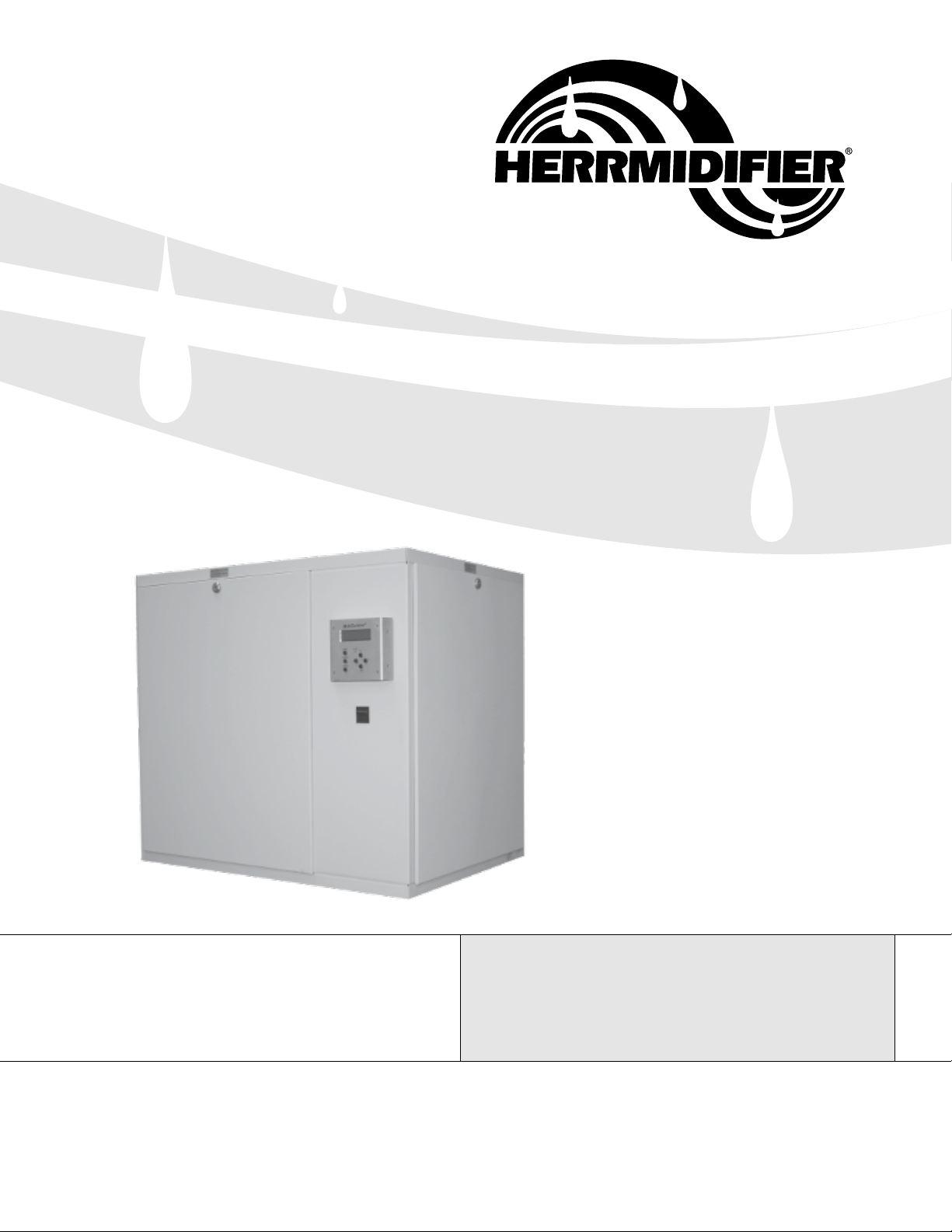
Engineered Humidification Systems
READ & SAVE THESE INSTRUCTIONS
Herrmersion RE Series
Installation, Operation, & Maintenance
Herrmidifier® | www.herrmidifier-hvac.com
Page 2

Installation, Operation, & Maintenance Manual
TABLE OF CONTENTS
Warranty ................................................................................................................................................................ 3
General Warnings & Installer Responsibility .......................................................................................................... 4
Model Number Nomenclature ................................................................................................................................ 4
Overall Unit Dimensions ........................................................................................................................................ 4
Receiving Instructions ............................................................................................................................................ 4
Pre-Installation Instructions ................................................................................................................................... 5
General Safety Requirements ............................................................................................................................... 5
Installation .............................................................................................................................................................. 5
Unit Location & Mounting ............................................................................................................................. 5
Plumbing ...................................................................................................................................................... 6
Steam Distribution ..................................................................................................................................... 6-8
Electrical ...................................................................................................................................................... 8
Installation Checklist .................................................................................................................................... 9
Wiring Diagrams.................................................................................................................................... 10-15
Control System .................................................................................................................................................... 16
Parameters Menu ...................................................................................................................................... 16
Status Menu ............................................................................................................................................... 17
Setpoints Menu .......................................................................................................................................... 17
Alarm Screen ............................................................................................................................................. 18
Clockset Screen ......................................................................................................................................... 18
User Password Settings ............................................................................................................................. 18
Control Conguration (Admin Only) ...................................................................................................... 18-19
Control Module Specications ........................................................................................................................ 20-21
Replacement Parts .............................................................................................................................................. 22
Maintenance Record Sheet ................................................................................................................................. 23
2 www.herrmidifier-hvac.com
Herrmersion RE
Page 3

Installation, Operation, & Maintenance Manual
I. WARRANTY
Limited 2-Year Warranty
Seller warrants the equipment of its manufacturing to be free
from defects in workmanship and material for a period of 24
months after shipment or 24 months after initial commissioning,
whichever occurs rst. This warranty is limited, however, to the
repair or replacement of defective equipment, which is returned,
freight prepaid, to Seller’s factory.
This limited warranty does not apply to any part or component
that is damaged in transit or when handling, has been subject
to misuse, negligence or accident, has not been installed, operated or serviced according to Seller’s instructions, or has been
operated beyond the factory-rated capacity or has been altered
in any way.
Seller’s liability is limited to replacement of defective parts or
components and does not include any cost of labor (including,
but not limited to, labor required to remove and/or reinstall any
defective part) other than Trion/Herrmidier factory labor.
Each of the Herrtronic series of steam generating humidiers
contains a plastic steam generating cylinder that is to be considered a routinely disposable part to be changed at regular maintenance intervals at the user’s expense. This steam generating
cylinder is not covered by this Warranty. If, after the rst installation of your Herrtronic humidier, you feel the steam generat-
ing cylinder is not operating normally, you should contact your
Herrmidier Representative with an explanation of the problem.
However, in the continuing operation of this humidier, replace-
ments of this part are your responsibility as part of routine maintenance.
Trion/Herrmidier shall not be responsible for loss of use of
any product, loss of time, inconvenience, or damage to other
equipment, or any other indirect or consequential damage with
respect to property whether as a result of breach of warranty,
neglect, or otherwise.
THE WARRANTIES AND LIABILITIES SET FORTH ARE IN
LIEU OF ALL OTHER WARRANTIES AND LIABILITIES, EXPRESSED OR IMPLIED, IN LAW OR IN FACT, INCLUDING IMPLIED WARRANTIES OF MERCHANTABILITY AND FITNESS
FOR PARTICULAR PURPOSE.
ATTENTION
READ THIS MANUAL, FACTORY INSTALLED OPTIONS
MANUAL, UNIT SUBMITTAL DATA SHEETS AND ALL LABELS
ATTACHED TO THE UNIT CAREFULY BEFORE ATTEMPTING TO INSTALL, OPERATE OR SERVICE THESE UNITS.
CHECK DATA PLATES FOR ELECTRICAL SPECIFICATIONS
AND MAKE CERTAIN THAT THESE AGREE WITH THOSE AT
THE POINT OF INSTALLATION. RECORD THE UNIT MODEL
AND SERIAL NUMBER IN THE SPACE PROVIDED. RETAIN
THIS DOCUMENT FOR FUTURE REFERENCE.
WARNING
IMPROPER INSTALLATION, ADJUSTMENT, ALTERATION,
SERVICE OR MAINTENANCE CAN CAUSE PROPERTY
DAMAGE, INJURY OR DEATH. THIS APPLIANCE MUST
BE INSTALLED BY A LICENSED CONTRACTOR OR QUALIFIED SERVICE PERSONNEL. READ THESE INSTALLATION,
OPERATING AND MAINTENANCE INSTRUCTIONS THOROUGHLY BEFORE INSTALLING OR SERVICING THE UNIT.
WARNING
INSTALL, OPERATE AND MAINTAIN UNIT IN ACCORDANCE
WITH MANUFACTURER’S INSTRUCTIONS TO AVOID ANY
CIRCUMSTANCES THAT MAY CAUSE PERSONAL INJURY
OR PROPERTY DAMAGE.
INSTALLER’S RESPONSIBILITY
THIS EQUIPMENT HAS BEEN RUN TESTED AND INSPECTED THOROUGHLY. IT HAS BEEN SHIPPED FREE FROM DEFECTS FROM OUR FACTORY. HOWEVER, DURING SHIPMENT AND INSTALLATION, PROBLEMS SUCH AS LOOSE
WIRES, LEAKS OR LOOSE FASTENERS MAY OCCUR. IT
IS THE INSTALLER’S RESPONSIBILITY TO INSPECT AND
CORRECT ANY PROBLEMS THAT MAY BE FOUND.
RECEIVING INSTRUCTIONS
INSPECT SHIPMENT IMMEDIATELY UPON ARRIVAL TO DETERMINE IF ANY DAMAGE HAS OCCURRED TO THE UNIT
DURING SHIPMENT. AFTER THE UNIT HAS BEEN UNCRATED, CHECK FOR ANY VISIBLE DAMAGE TO THE UNIT. IF
ANY DAMAGE IS FOUND, THE CONSIGNEE SHOULD SIGN
THE BILL OF LADING INDICATING SUCH DAMAGE AND IMMEDIATELY FILE A CLAIM FOR DAMAGE WITH THE TRANSPORTATION COMPANY.
The foregoing shall constitute the total liability of seller in the
case of defective performance of all or any of the equipment or
services provided to Buyer. Buyer agrees to accept and hereby
accepts the foregoing as the sole and exclusive remedy for any
breach or alleged breach of warranty by Seller.
Herrmersion RE
www.herrmidifier-hvac.com
3
Page 4
Installation, Operation, & Maintenance Manual
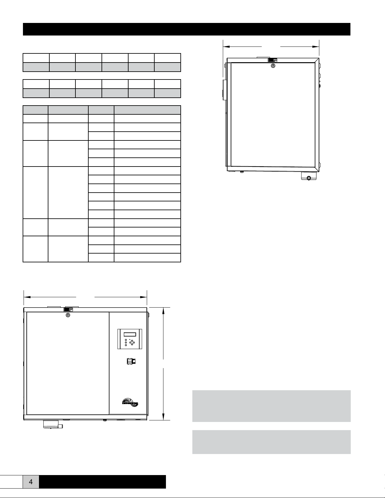
MODEL NUMBER NOMENCLATURE
RE * * * * *
Model Prex
RE S P 480 3 45
Model Prex
Position Meaning Option Description
Prex Product Family RE RE Electric-to-steam
1
2 Control Type
3 Voltage
4 Phase
5 Capacity (lb/hr)
1 2 3 4 5
1 2 3 4 5
Size (number
of tanks)
S Single Tank
D Dual Tank
P Proportional Control
I Proportional + Integral
H Custom (on/off humidistat)
208
240
380
415
480
600
1 Single Phase
3 Three Phase
30 (2) 5 KW heaters
45 (3) 5 KW heaters
90 (6) 5 KW heaters
21.29
RECEIVING INSTRUCTIONS
Inspect shipment immediately upon arrival to determine if
there is any noticeable freight damage to the packaging.
After the unit has been unpacked, check for any damage
to the unit. Take notice that the drain cup mounted to the
underside of the unit is not cracked or damaged.
OVERALL UNIT DIMENSIONS
27.75
25.20
If any damage is found, the consignee should sign the bill of
lading indicating such damage and immediately le a claim
for that damage with the transportation company.
PRE-INSTALLATION INSTRUCTIONS
After the unit is received and unpacked, check the external
data plate and all labels on the unit for electrical and
operational specications to conrm that these agree with
those at point of installation.
Note: It is the owner’s responsibility to provide any
scaffolding or other apparatus required to perform emergency
service or annual/periodic maintenance to this equipment.
GENERAL SAFETY REQUIREMENTS
WARNING
Open all disconnect switches before installing the unit.
Failure to do so could result in personal injury or death from
electrical shock.
WARNING
Failure to comply with the general requirements may result in
extensive property damage, severe personal injury or death.
4 www.herrmidifier-hvac.com
Herrmersion RE
Page 5
Installation, Operation, & Maintenance Manual
WARNING
Never service any component without rst disconnecting all
electrical supplies to the unit or severe personal injury or
death could occur.
CAUTION
Insure that all power sources conform to the unit requirements
or damage to the unit may result.
These units have been designed for any tap, softened, de-
ionized (DI) or reverse osmosis (RO) water applications.
With tap/softened water, an adjustable drain cycle and
skimmer cycle are provided to automatically drain away
some water contaminants; reducing cleaning intervals. For
DI/RO water, the system is virtually maintenance free. The
skimming cycle may be deactivated via the keypad.
Follow installation instructions CAREFULLY to avoid creating
unsafe conditions. All electrical wiring should be done and
checked by a qualied electrician using copper conductors
only. All piping connections should be made and leak-tested
by a qualied service technician, per instructions in this
manual.
Make certain that the power source conforms with to the
electrical requirements of the unit. Disconnect power before
installing or servicing the unit. If power disconnect is out of
visual sight, lock it into open position and tag it to prevent
unexpected application of power. Failure to do so could
result in fatal electrical shock.
WARNING
Do not depend upon a unit control switch or other switch as
the sole means of disconnecting power when installing or
servicing the unit. Always disconnect power at main circuit
breaker. Failure to do so could result in fatal electrical shock.
Special attention should be given to grounding this unit. To
prevent the risk of electrocution, the unit must be securely
and adequately grounded. This should be accomplished by
connecting a grounded conductor from the service panel to
the grounding lug located inside the control section of the
unit. To ensure proper ground, a qualied eld technician
must test the grounding means.
Do not defeat safety interlocks, such as the high temperature
limit or door switch. Do not attempt to operate the unit without
the doors installed.
In cases in which property damage may result from
malfunction of this unit, a backup system should be used.
INSTALLATION
WARNING
Open all disconnect switches and secure in that position
before installing unit. Failure to do so may result in personal
injury or death from electrical shock.
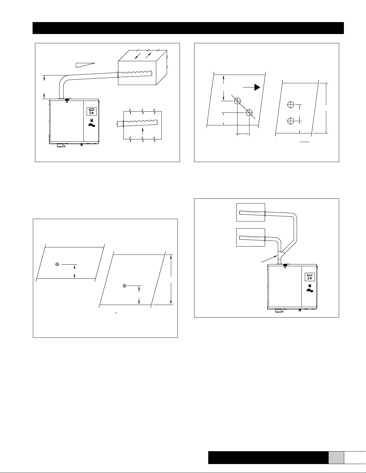
UNIT LOCATION & MOUNTING
The Herrmersion – RE unit is designed to be mounted on a
wall and should be located as close to the dispersion means
as possible (i.e. close to the duct being served with the
steam). This will minimize energy losses.
The unit requires electrical and plumbing connections and
should be mounted in such a way to facilitate access to these
connections.
In order for the magnetic water level switches and the
skimmer function to operate properly, the unit must be
mounted level and plumb with reference to the front and top
of the unit.
The cabinet is designed to safely dissipate heat to protect
the electronics. Herrmersion – RE humidiers, steam piping
and any other accessories should be located in a manner to
facilitate routine inspection and any necessary maintenance.
The unit should not be located above (false ceilings) or
around valuable property where a malfunction could cause
damage. Minimum clearance around the cabinet must be
maintained.
Minimum Access Requirements
Left 2”
Right 24”
Top 12”
Bottom 10”
Front 36”
Minimum access is 36” to the front for periodic removal of the
steam tank for service and 24” to the right side for access to
the electrical components.
Four lag bolts (2) 5/16” and (2) ¼” are supplied for securing
the unit to the wall. Install the top two lag bolts (5/16”)
according to the dimensions shown below. Hang the unit
on the wall, and then install the bottom two lag bolts (1/4”).
Finally, secure all four lag bolts. Be sure the unit is level and
mounted directly to a wall constructed of wood studs at least
2” thick (or equivalent).
WARNING
Do not place unit in a location where service personnel can
not safely service this equipment or personal injury could
occur.
Herrmersion RE
Mounting location must be capable of supporting the entire
weight of the unit. Please refer to the previous table for
operating weight of the unit.
www.herrmidifier-hvac.com
5
Page 6
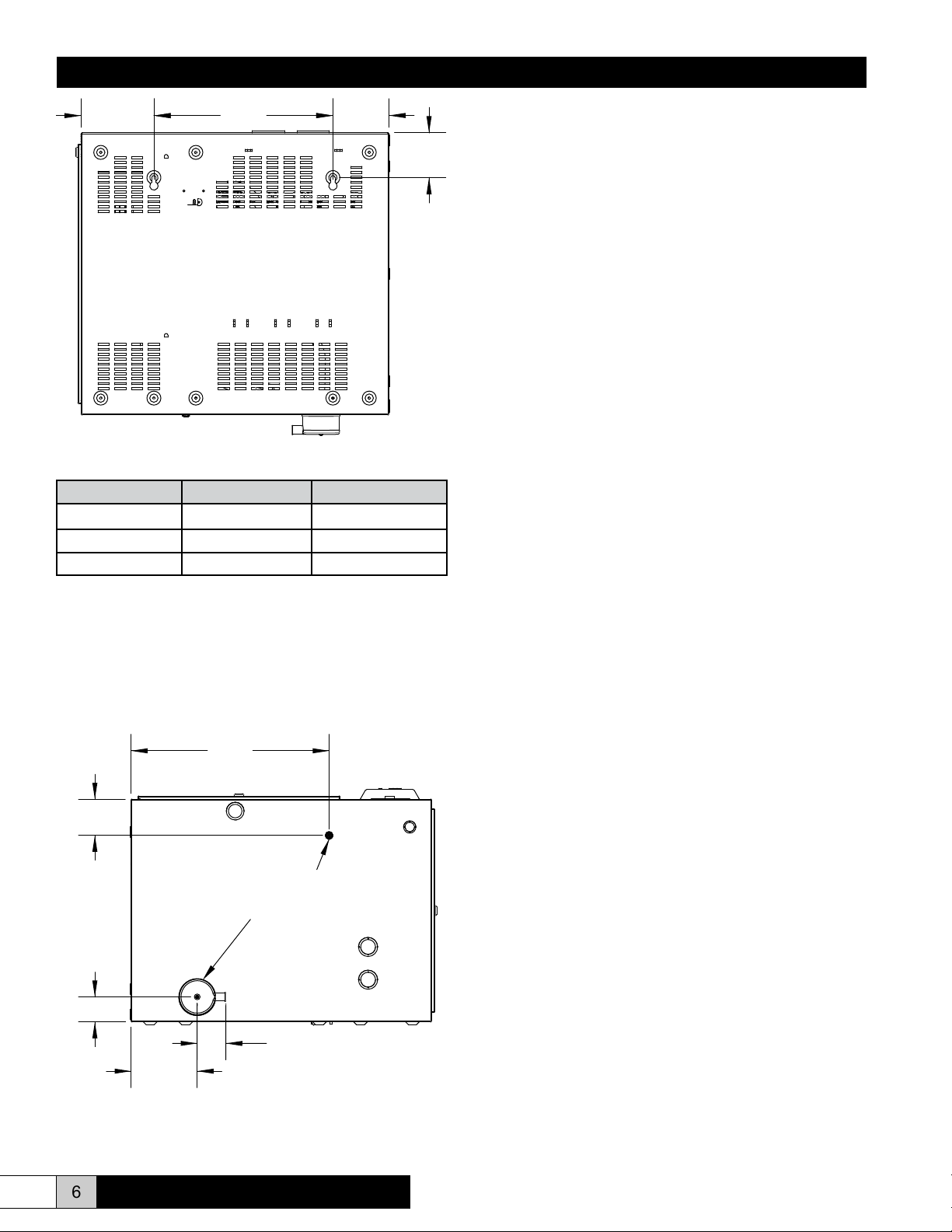
Installation, Operation, & Maintenance Manual
6.50 16.00
5.00
4.00
Back View (Mirror the hole pattern on mounting surface)
Model Number Shipping Weight Operating Weight
RESX-XXX-X-30 125 lbs. 237 lbs.
RESX-XXX-X-45 128 lbs. 240 lbs.
RESX-XXX-X-90 134 lbs. 246 lbs.
“X” denotes weight independent portion of model number
PLUMBING
2. Connect the water supply to the bottom of the unit using
1/4” push-to-lock tting. Supply water line should be
sized so that line pressure loss is minimal.
3. A drain line should be extended from the drain
connection to a sanitary waste. A minimum 1” ID copper
tube is recommended. If PVC is used, local codes
may require lower drain water temperature; enable the
drain tempering feature (see the control section of this
manual).
4. The skim/overow connection on the front of the tank only
needs to be connected if the humidier is being supplied
raw water containing signicant mineral concentrations.
Deionized or reverse osmosis (technical waters) may be
used and do not require the use of this feature. The
skimming cycle allows oating debris to leave the tank
through the overow drain and will reduce maintenance
intervals.
5. If using the skimmer connection, a trap must be installed
in the line so that steam can not escape from the
skimming connection during operation.
STEAM DISTRIBUTION
Herrmersion units may be used with stainless steel duct
dispersion tubes for injecting steam directly into the ductwork.
A minimum of 3 feet downstream clearance is required
for many applications; however differing psychrometric
conditions may require a greater distance. If required, consult
the factory to design a guaranteed absorption Herricane –
CS Steam Distribution System.
To make the necessary connections for water ll, drain, and
overow/skim; the following steps are required. Refer to the
illustration below for dimensional information regarding the
ll & drain connections.
18.13
3.31
Supply Connection
Drain Connection
2.29
2.63 REF.
6.05
Mount the unit as close to the dispersion tube as possible.
Use 1.5” Type L insulated copper whenever the length of run
exceeds 20 feet. Do not exceed a 30 foot run as the capacity
of the humidier may be decreased by as much as 15% and
the increased static pressure could cause problems with the
ll system. The maximum duct static pressure is 5” W.C.
Any insulation inside the bulk evaporation zone (inside the
ductwork) should be removed.
Steam holes in factory supplied duct dispersion tubes are
located 2” from the mounting plate and are designed for a
maximum 1” thick duct wall. Consult the factory if special
hole locations are required.
Do not install or mount standard dispersion tubes in a vertical
position or in a vertical airow application. Special dispersion
tubes are available from the factory for installations which
require vertically mounted tubes or horizontal tubes with
vertical airow.
1. Install an external shut-off valve between the water
supply and the humidier for ease in servicing the unit.
6 www.herrmidifier-hvac.com
Herrmersion RE
Page 7
Installation, Operation, & Maintenance Manual
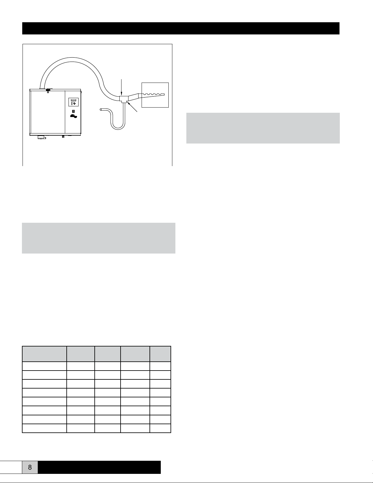
Standard Duct Distribution
MIN. 8% (1" PER FOOT)
10" MIN.
(254mm)
NO SAGS
ALLOWED
HORIZONTAL DUCT
STEAM DISCHARGE MUST ALWAYS
BE FROM THE TOP OF DISTRIBUTOR
VERTICAL DUCT
The rubber vapor hose carries the steam to the dispersion
tube and condensate back to the unit tank. It must have an
8% (1” per foot) pitch back to the unit. Support the vapor
hose so that it maintains proper pitch when the unit is in
operation.
Dual Distribution Tubes
DUCT HEIGHT
10" - 16"
(254MM) - (406MM)
DUCT HEIGHT > 16"
(406mm)
AIR
6.5" (165mm)
3.00" (76mm)
8.00
(203mm)
FLOW
(76mm)
h (in)=6+
h
3"
(H-15)
2
H
Units above 45 pounds per hour of steam will use two duct
dispersion tubes. Refer to the diagram above for mounting
location.
Single to Dual Duct Distribution
Single Distribution Tube
DUCT HEIGHT
10" - 16"
(254MM) - (406MM)
DUCT HEIGHT > 16"
(406mm)
(76mm)
3"
H
h
H
-5" (127mm)
h =
2
Units up to 45 pounds per hour of steam will use one steam
distribution tube. Refer to the diagram above for mounting
location.
EST-255
"Y" CONNECTOR
If you must split the discharge of one steam outlet into two
ducts with the same static pressure, a “Y” connector is
available from the factory. The length of vapor hose after
the “Y” connector must be the same to ensure equal steam
distribution.
Herrmersion RE
www.herrmidifier-hvac.com
7
Page 8
Installation, Operation, & Maintenance Manual
Unavoidable Low Spot or Sagging Vapor Hose
EST-250
CONDENSATE
TRAP
1/2"
TUBE
TO
DRAIN
AT LOWEST
POSSIBLE
POINT
If any low spots are present in the vapor line or the unit is
mounted higher than the dispersion system, a condensate
trap must be mounted at the lowest point in the line. This will
act to remove any pooled condensate from the steam line
and prevent spitting in the duct.
ELECTRICAL
WARNING
Open all disconnect switches before installing the unit.
Failure to do so could result in personal injury or death from
electrical shock.
A wiring diagram is located inside the control cabinet. The
wiring between the control cabinet and the humidier unit
must be 105 °C rated wire. Use copper conductors only.
Please refer to the Control section in this manual for
information regarding electrical connections to be made
directly to the control system.
NOTE: Only qualied electrical personnel should perform
installation and start-up procedures.
WARNING
Open all disconnect switches before installing the unit.
Failure to do so could result in personal injury or death from
electrical shock.
The following pages contain unit wiring diagrams. Please
identify the applicable wiring diagram primarily by the number
of heating elements present on your unit. Refer to the chart
above. Units designed for 30 lbs/hr of steam output will have
2 heating elements, units designed for 45 lbs/hr of steam
output will have 3 heating elements and units designed for
90 lbs/hr of steam output will have 6 heating elements. The
only other difference between these diagrams pertains to the
control transformer. Please identify the appropriate wiring
diagram for your unit on the following pages.
Ensure that adequate service is available to carry 125% of
the rated unit amperage. Field wiring of the main power
supply is connected directly to the main power contactor
located inside the right side electrical compartment. Please
refer to the wiring diagram appropriate for the model
Herrmersion you have. A separate grounding lug is provided
for the ground wire. This is also located inside the right side
electrical compartment. Install short circuit & over-current
protection in accordance with the National Electric Code,
State, and local electrical codes.
Model Capacity/Amperage Table
Unit Model Max.
Capacity
RES_-240-1-30 30 lb/hr 240/1 2 41.7
RES_-480-1-30 30 lb/hr 480/1 2 20.8
RES_-208-3-45 45 lb/hr 208/3 3 41.6
RES_-240-3-45 45 lb/hr 240/3 3 36.1
RES_-480-3-45 45 lb/hr 480/3 3 18.0
RES_-600-3-45 45 lb/hr 600/3 3 14.4
RES_-480-3-90 90 lb/hr 480/3 6 36.1
RES_-600-3-90 90 lb/hr 600/3 6 28.9
Voltage/
Phase
Qty.
Elements
Total
Amps
8 www.herrmidifier-hvac.com
Herrmersion RE
Page 9

Installation, Operation, & Maintenance Manual
INSTALLATION CHECK LIST
AIR FLOW IS HORIZONTAL OR VERTICAL UPFLOW
*A SPECIAL PIPE IS REQUIRED FOR VERTICAL DOWNFLOW,
OR A VERTICAL DISTRIBUTOR PIPE IN A HORIZONTAL
AIR FLOW.
MAKE SURE ALL HIGH VOLTAGE
ELECTRICAL CONNECTIONS ON
STEAM CYLINDER ARE TIGHT
DURING FILL CYCLE CHECK TO SEE IF ANY
WATER IS DRAINING FROM UNIT. A LOT OF
WATER FLOWING OUT OF THE UNIT WOULD
INDICATE EXCESSIVE WATER PRESSURE.
REDUCE THROUGH METERING FILL SOLENOID
OR SUPPLY VALVE TO HUMIDIFIER. A SMALL
AMOUNT OF WATER IS NOT UNCOMMON.
(15-20 in/lbs)
3/4" MIN. I.D./1" MAX O.D.
FLEXIBLE DRAIN CONNECTION
8"
RECOMMENDED
NO UNTRAPPED LOW SPOTS
IN STEAM SUPPLY.
4"
RECOMMENDED
MAKE SURE ALL HIGH VOLTAGE
ELECTRICAL CONNECTIONS
ARE TIGHT.
POWER SUPPLY:
1. MATCHES DATA PLATE
2. IS PROPERLY GROUNDED
3. CAN CARRY AT LEAST 125%
OF RATE AMP DRAW
4. DISCONNECT SUPPLIED BY
OTHERS.
6" MIN. LENGTH OF 1-1/4" MIN. I.D. COPPER LINE.
IF PVC IS USED, LOCAL CODES REQUIRE A LOWER
TEMPERATURE DRAIN WATER IS NOT UNCOMMON.
BALANCE OF DRAIN LINE TO BE 1" MIN. I.D.
WITH A MINIMUM PITCH OF 1/8" PER 12" OF RUN
ENSURE OVERFLOW PIPING IS INSTALLED
AND TIGHT IF USING RAW WATER. A 5-6” P-TRAP IS
REQUIRED TO ENSURE STEAM DOES NOT ENSUE
FROM THE OVERFLOW PIPING. OVERFLOW
IS NOT REQUIRED WITH DI/RO WATER. SKIMMING
MUST BE DISABLED IN THE CONTROL SETTINGS.
Herrmersion RE
www.herrmidifier-hvac.com
9
Page 10

Installation, Operation, & Maintenance Manual
LEVEL SWITCH
VALVE
FILL
REAR OF KEYPAD/DISPLAY UNIT
0-5VDC HIGH LIMIT HUMIDITY
0-5VDC HUMIDITY SIGNAL
0-5VDC DEMAND SIGNAL
SIGNAL (IF REQUIRED)
AIR PROVING SWITCH
YELLOW
YELLOW
VALVE
DRAIN
BLACK
BLACK
FUSE 2 (2A)
FUSE 1 (2A)
FIELD CONTROL WIRING CONNECTIONS
OR
0
H3H4 H2 H1
208
REAR OF ON/OFF SWITCH
X1
240
480
BLACK
BLACK
X3
RED
TRANSFORMER
RED
X2
24V
WHITE
FUSE 3 (4A)
BLUE
WHITE
TERMINAL
BLOCK
RED
BLUE
BUS
2
4
6
8
10
12
COMMON
24V
24V
HIGH
LOW
BROWN
BROWN
YELLOW
WHITE
BLACK
RED
YELLOW
1
3
RED
5
RED
BROWN
7
9
11
WHITE
RED
RED
YELLOW
YELLOW
GR AY
SEE VIEW BELOW FOR
FIELD CONTROL WIRING
CONNECTIONS
GR AY
CONTROLLER
YELLOW
BLACK
RED
WHITE
BLUE
OVERTEMPERATURE
SWITCH
BLUE
DOOR INTERLOCK SWITCH
BLUE
GROUNDED
TO CHASSIS
GR AY
BLACK
265154-001 REV. B
1-PHASE INPUT
BY INSTALLER
208/240/480V
2-HEATER UNIT (1-PHASE)
TRANSFORMER
BLACK
14
L3
L2
L1
BLUE
BLUE
13
T3
T2
T1
CONTACTOR
A1
A2
SSR = SOLID STATE RELAY
10 www.herrmidifier-hvac.com
WHT/ORG
RED
BROWN
YELLOW
GR AY
WHITE/ORANGE
WHITE/ORANGE
SSR1
L1
-
T1
+
BLUE
WHT/ORG
BLUE
WHITE
RED
IMMERSION
HEATERS
RED
WHITE
Herrmersion RE
Page 11

Installation, Operation, & Maintenance Manual
LEVEL SWITCH
VALVE
FILL
REAR OF KEYPAD/DISPLAY UNIT
0-5VDC HIGH LIMIT HUMIDITY
0-5VDC HUMIDITY SIGNAL
0-5VDC DEMAND SIGNAL
SIGNAL (IF REQUIRED)
AIR PROVING SWITCH
YELLOW
YELLOW
VALVE
DRAIN
BLACK
BLACK
FUSE 2 (2A)
FUSE 1 (2A)
FIELD CONTROL WIRING CONNECTIONS
OR
0
H3H4 H2 H1
208
REAR OF ON/OFF SWITCH
X1
240
480
BLACK
BLACK
X3
RED
TRANSFORMER
RED
X2
24V
WHITE
FUSE 3 (4A)
BLUE
WHITE
TERMINAL
BLOCK
RED
BLUE
BUS
2
4
6
8
10
12
COMMON
24V
24V
HIGH
LOW
BROWN
BROWN
YELLOW
WHITE
BLACK
RED
YELLOW
1
3
RED
5
RED
BROWN
7
9
11
WHITE
RED
RED
YELLOW
GR AY
YELLOW
GR AY
SEE VIEW BELOW FOR
FIELD CONTROL WIRING
CONNECTIONS
CONTROLLER
YELLOW
BLACK
RED
WHITE
BLUE
OVERTEMPERATURE
SWITCH
BLUE
DOOR INTERLOCK SWITCH
BLUE
GROUNDED
TO CHASSIS
3-PHASE INPUT
BY INSTALLER
265153-001 REV. B
TRANSFORMER
208/240/480V
3-HEATER UNIT
Herrmersion RE
WHT/ORG
RED
BROWN
YELLOW
GR AY
BLACK
BLACK
14
L3
L2
L1
BLUE
BLUE
A1
SSR = SOLID STATE RELAY
WHT/ORG
SSR1
WHT/ORG
GR AY
13
T3
T2
T1
CONTACTOR
A2
-
+
WHITE/ORANGE
WHITE/ORANGE
SSR2
L1
T1
L1
-
T1
+
BLUE
WHT/ORG
www.herrmidifier-hvac.com
BLUE
WHITE
RED
IMMERSION
HEATERS
RED
WHITE
11
Page 12

RED
LEVEL SWITCH
VALVE
FILL
BLUE
OVERTEMPERATURE
SWITCH
HIGH
LOW
BROWN
BROWN
BLUE
YELLOW
YELLOW
RED
FIELD CONTROL WIRING
SEE VIEW BELOW FOR
CONNECTIONS
WHITE
YELLOW
BLACK
GR AY
GR AY
RED
DOOR INTERLOCK SWITCH
BLUE
CONTROLLER
Installation, Operation, & Maintenance Manual
REAR OF KEYPAD/DISPLAY UNIT
0-5VDC HIGH LIMIT HUMIDITY
0-5VDC HUMIDITY SIGNAL
0-5VDC DEMAND SIGNAL
SIGNAL (IF REQUIRED)
AIR PROVING SWITCH
YELLOW
YELLOW
VALVE
DRAIN
BLACK
BLACK
FUSE 2 (2A)
FUSE 1 (2A)
FIELD CONTROL WIRING CONNECTIONS
OR
0
H3H4 H2 H1
208
REAR OF ON/OFF SWITCH
X1
240
480
BLACK
BLACK
X3
RED
TRANSFORMER
RED
X2
24V
WHITE
FUSE 3 (4A)
BLUE
WHITE
TERMINAL
BLOCK
RED
BLUE
BUS
2
4
6
8
10
12
COMMON
24V
24V
YELLOW
WHITE
BLACK
RED
YELLOW
1
3
RED
5
RED
7
9
11
BROWN
WHITE
GROUNDED
TO CHASSIS
GR AY
BLACK
BLACK
3-PHASE INPUT
BY INSTALLER
265152-001 REV. B
TRANSFORMER
208/240/480V
6-HEATER UNIT
14
L3
L2
L1
BLUE
BLUE
SSR = SOLID STATE RELAY
A1
WHT/ORG
SSR1
WHT/ORG
13
T3
T2
T1
CONTACTOR
A2
L1
-
T1
+
12 www.herrmidifier-hvac.com
WHT/ORG
BLUE
RED
BROWN
YELLOW
GR AY
WHITE/ORANGE
WHITE/ORANGE
SSR2
L1
-
T1
+
WHT/ORG
BLUE
WHITE
RED
IMMERSION
HEATERS
RED
WHITE
Herrmersion RE
Page 13

Installation, Operation, & Maintenance Manual
LEVEL SWITCH
VALVE
FILL
REAR OF KEYPAD/DISPLAY UNIT
0-5VDC HIGH LIMIT HUMIDITY
0-5VDC HUMIDITY SIGNAL
0-5VDC DEMAND SIGNAL
SIGNAL (IF REQUIRED)
AIR PROVING SWITCH
YELLOW
YELLOW
VALVE
DRAIN
BLACK
FUSE 2 (2A)
FUSE 1 (2A)
FIELD CONTROL WIRING CONNECTIONS
OR
H6
600
480
H4H5 H3 H1H2
380
REAR OF ON/OFF SWITCH
X1
240
208
BLACK
BLACK
BLACK
0
X3
RED
TRANSFORMER
RED
24V
WHITE
WHITE
FUSE 3 (4A)
BLUE
TERMINAL
BLOCK
RED
BLUE
BUS
2
4
6
8
10
12
COMMON
24V
24V
HIGH
LOW
BROWN
BROWN
YELLOW
WHITE
BLACK
RED
YELLOW
1
3
RED
5
RED
BROWN
7
9
11
WHITE
RED
RED
YELLOW
GR AY
YELLOW
GR AY
SEE VIEW BELOW FOR
FIELD CONTROL WIRING
CONNECTIONS
CONTROLLER
YELLOW
BLACK
RED
WHITE
BLUE
OVERTEMPERATURE
SWITCH
BLUE
DOOR INTERLOCK SWITCH
BLUE
GROUNDED
TO CHASSIS
1-PHASE INPUT
BY INSTALLER
TRANSFORMER
208/240/415/480/600V
2-HEATER UNIT (1-PHASE)
265157-001 REV. A
Herrmersion RE
WHT/ORG
RED
BROWN
YELLOW
GR AY
BLACK
BLACK
14
L3
L2
L1
BLUE
BLUE
A1
SSR = SOLID STATE RELAY
GR AY
13
T3
T2
T1
CONTACTOR
A2
WHITE/ORANGE
WHITE/ORANGE
SSR1
-
+
L1
T1
BLUE
WHT/ORG
www.herrmidifier-hvac.com
BLUE
WHITE
RED
IMMERSION
HEATERS
RED
WHITE
13
Page 14

RED
LEVEL SWITCH
VALVE
FILL
BLUE
OVERTEMPERATURE
SWITCH
HIGH
LOW
BROWN
BROWN
BLUE
YELLOW
YELLOW
RED
SEE VIEW BELOW FOR
FIELD CONTROL WIRING
CONNECTIONS
WHITE
YELLOW
BLACK
GR AY
GR AY
RED
DOOR INTERLOCK SWITCH
BLUE
CONTROLLER
Installation, Operation, & Maintenance Manual
REAR OF KEYPAD/DISPLAY UNIT
0-5VDC HIGH LIMIT HUMIDITY
0-5VDC HUMIDITY SIGNAL
0-5VDC DEMAND SIGNAL
SIGNAL (IF REQUIRED)
AIR PROVING SWITCH
YELLOW
YELLOW
VALVE
DRAIN
BLACK
FUSE 2 (2A)
FUSE 1 (2A)
FIELD CONTROL WIRING CONNECTIONS
OR
H6
600
480
H4H5 H3 H1H2
380
REAR OF ON/OFF SWITCH
X1
240
208
BLACK
BLACK
BLACK
0
X3
RED
TRANSFORMER
RED
24V
WHITE
WHITE
FUSE 3 (4A)
BLUE
TERMINAL
BLOCK
RED
BLUE
BUS
2
4
6
8
10
12
COMMON
24V
24V
YELLOW
WHITE
BLACK
RED
YELLOW
1
3
RED
5
RED
7
9
11
BROWN
WHITE
GROUNDED
TO CHASSIS
GR AY
BLACK
BLACK
3-PHASE INPUT
BY INSTALLER
TRANSFORMER
208/240/415/480/600V
265156-001 REV. A
3-HEATER UNIT
14
L3
L2
L1
BLUE
BLUE
SSR = SOLID STATE RELAY
A1
WHT/ORG
SSR1
WHT/ORG
13
T3
T2
T1
CONTACTOR
A2
L1
-
T1
+
14 www.herrmidifier-hvac.com
WHT/ORG
BLUE
RED
BROWN
YELLOW
GR AY
WHITE/ORANGE
WHITE/ORANGE
SSR2
L1
-
T1
+
WHT/ORG
BLUE
WHITE
RED
IMMERSION
HEATERS
RED
WHITE
Herrmersion RE
Page 15

RED
LEVEL SWITCH
VALVE
FILL
BLUE
OVERTEMPERATURE
SWITCH
HIGH
LOW
BROWN
BROWN
BLUE
YELLOW
YELLOW
RED
SEE VIEW BELOW FOR
FIELD CONTROL WIRING
CONNECTIONS
WHITE
YELLOW
BLACK
GR AY
GR AY
RED
DOOR INTERLOCK SWITCH
BLUE
CONTROLLER
Installation, Operation, & Maintenance Manual
REAR OF KEYPAD/DISPLAY UNIT
0-5VDC HIGH LIMIT HUMIDITY
0-5VDC HUMIDITY SIGNAL
0-5VDC DEMAND SIGNAL
SIGNAL (IF REQUIRED)
AIR PROVING SWITCH
YELLOW
YELLOW
VALVE
DRAIN
BLACK
FUSE 2 (2A)
FUSE 1 (2A)
FIELD CONTROL WIRING CONNECTIONS
OR
H6
600
480
H4H5 H3 H1H2
380
REAR OF ON/OFF SWITCH
X1
240
208
BLACK
BLACK
BLACK
0
X3
RED
TRANSFORMER
RED
24V
WHITE
WHITE
FUSE 3 (4A)
BLUE
TERMINAL
BLOCK
RED
BLUE
BUS
2
4
6
8
10
12
COMMON
24V
24V
YELLOW
WHITE
BLACK
RED
YELLOW
1
3
RED
5
RED
BROWN
7
9
11
WHITE
GROUNDED
TO CHASSIS
3-PHASE INPUT
BY INSTALLER
TRANSFORMER
208/240/415/480/600V
265155-001 REV. A
6-HEATER UNIT
Herrmersion RE
WHT/ORG
RED
BROWN
YELLOW
GR AY
BLACK
BLACK
14
L3
L2
L1
BLUE
BLUE
A1
SSR = SOLID STATE RELAY
WHT/ORG
SSR1
WHT/ORG
GR AY
13
T3
T2
T1
CONTACTOR
A2
-
+
WHITE/ORANGE
WHITE/ORANGE
SSR2
L1
T1
L1
-
T1
+
BLUE
WHT/ORG
www.herrmidifier-hvac.com
BLUE
WHITE
RED
IMMERSION
HEATERS
RED
WHITE
15
Page 16

Installation, Operation, & Maintenance Manual
CONTROL SYSTEM
The Herrmersion – RE is supplied with a microprocessor
based native BACnet controller that provides complete
control of humidier operations. The controller comes pre-
programmed for optimum performance. System settings
can be adjusted via the on-board keypad user interface.
When connected to a building management system,
the Herrmersion – RE communicates via some typical
communication protocols; such as, BACnet, Modbus, N2,
or LonWorks. LonWorks requires an additional expansion
card.
Display Unit
SSR Output Status, Fill Valve Output Status, and Drain Valve
Output Status. A “0” indicates an “open” or “OFF” condition.
A “1” indicates a “made” or “ON” condition.
Home Screen
The Home screen displays a list of menus which allow
the user to modify system parameters, check the status of
inputs/outputs/alarm, congure set-points, set the clock,
or access the factory conguration menu. The Set-points
menu will only be displayed if the unit is congured for standalone P+I control. The Cong menu will only be displayed
if the operator is logged into the system as Administrator.
The standard Administrator password is factory set to 2222.
Setpoints and Parameters may only be changed if a User is
logged into the system.
The display unit is a 2 line by 16 character backlit LCD display
that provides easy access to system input information,
system status, adjustable system parameters, and system
alarms. An intuitive button selection allows simple navigation
of the menu system. An LED illuminates when the system
encounters an alarm condition or enters an automatic drain
cycle congurable through the keypad.
Standby Screen
The Standby Screen is active only when the keypad is not
being used. It displays basic information such as the unit
model conguration, Operating Status, Output Percentage,
and Input Signal Percentage. This may be a demand signal
input or a relative humidity percentage received from a
humidity transmitter depending upon how the equipment is
congured. In the upper right corner, a string of 1’s and 0’s
provides a quick glance at the status of some key I/O points.
From left to right, these are Air Flow Switch Input Status, Low
Water Level Switch Input Status, Contactor Output Status,
To select a menu option, use the < and > buttons to navigate
vertically through the menu selections until the desired menu
is surrounded by brackets. Pressing the ENTER button one
time will navigate the system to the menu screen you have
selected.
To exit a menu, press HOME once, and the display will return
to the Home screen.
Parameters Screen
The Parameters menu contains a list of system parameters
that may be congured by the operator.
• Auto DRN – If ON, unit will drain periodically according to
the values set by the DRN Int & DRN Time parameters. If
OFF, the unit will never initiate a timed drain. De-ionized
16 www.herrmidifier-hvac.com
Herrmersion RE
Page 17

Installation, Operation, & Maintenance Manual
or reverse osmosis water applications rarely require the
Auto DRN feature to be enabled as the water contains
very low dissolved solids.
• DRN Int – Drain Interval is the interval at which the unit
will initiate a timed drain. The default interval is factory
set at 24 hours.
• DRN Time – Drain Time is the amount of time the drain
valve will remain open if a timed drain is active. The
DRN Time is factory set at 5 minutes.
• Skim Time – Skim Time is the amount of time the unit
will continue lling to skim the surface of the water every
time a ll cycle is active. This feature may be set to zero
if the system is operating with very clean water; such as
de-ionized water. The factory Skim Time is 60 seconds.
Low water pressure may require that this setting be
increased so that the unit will skim.
• DRN Tmpr – Drain Tempering will activate the ll valve
anytime the drain valve is active. This feature acts to
lower the drain water temperature by diluting the drain
water with cold ll water. Water ensuing from the
skimmer port on the tank is not tempered. An external
drain water tempering device may be required. Please
consult the factory for information about the Drain
Tempering Reservoir, available separately.
• Force DRN – Force Drain is used to manually initiate a
drain cycle. The drain valve will remain active until this
parameter is set to OFF by the operator.
• RETURN – Returns the operator to the Home screen.
output.
• AF Switch – This displays whether the air proving switch
is OPEN or MADE. OPEN indicates a lack of airow.
MADE indicates that the switch contacts are closed
indicating that airow is present.
• Contactor – This displays ON/OFF status of the main
power contactor. This is monitoring the status of the
auxiliary contact on the main power contactor.
• Drain Val. – This displays the ON/OFF status of the drain
valve output.
• Fill Valve – This displays the ON/OFF status of the ll
valve output.
• Full Water – This displays the OPEN/MADE status of
the upper water level oat switch. Each time this switch
opens, the unit will act to rell the tank for continued
humidication if a demand is present.
• Low Water – Displays the OPEN/MADE status of the
lower water level oat switch. This switch must be
MADE in order for the heating elements to be energized.
• HL Input – Displays the relative humidity percentage
being sensed by the High Limit humidity sensor.
This item will not show in the menu unless the unit is
congured for stand-alone P+I control. If the unit has a
High Limit humidistat in lieu of a transmitter, this menu
item will read High Limit and the status will read OPEN
or MADE to indicate the status of the humidistat (switch).
Setpoints Screen
Status Menu
The Status menu contains a list of system inputs/outputs that
may be monitored by the operator.
• Input – This displays the percentage of demand when the
unit is congured for Proportional only operation. The
demand signal is received from a building management
system or from a remote humidity controller. This
displays the controlled relative humidity percentage
when the unit is congured for stand-alone P+I control.
The signal is received from a humidity transmitter
mounted in the controlled environment.
• Output – This displays the percentage of maximum unit
The Setpoints Screen will only be visible on units that are
congured for stand-alone P+I control. The HOME screen
will display RES-I. This means that a control humidity sensor
and high limit humidity sensor need to be connected to inputs
1 & 2 of the control board. Please see the wiring diagram
appropriate for the unit model being installed.
• Hum. SP – The user may enter the control humidity
setpoint here. Default = 40%RH.
• Max HL% – The operator may enter the maximum
allowable duct high limit %RH here. Default = 80%RH
• HL Range – The High Limit range sets the percentage
offset where the unit will begin to throttle the unit output
proportionally between the Max. HL% minus the HL
Range. Example: If the Max. HL% is set to 80% and
the HL Range is 10%, the unit will be limited to 50% of
maximum output if the high limit duct sensor is reading
75% relative humidity in the duct.
• Max. Cap. – Maximum Capacity allows the operator to
limit the maximum unit output based on a percentage.
Example: If the unit has a maximum capacity of 90 lb/
Herrmersion RE
www.herrmidifier-hvac.com
17
Page 18

Installation, Operation, & Maintenance Manual
hr, the user may limit the unit to 80 lb/hr by setting this
to 89%.
• Low Hum. – This allows the operator to trigger a low
humidity alarm if the control humidity falls below a
certain value.
NOTE: Some units may be congured with High Limit
humidistats in lieu of proportional high limit devices. If the unit
is using a humidistat for the high limit device, the setpoints
menu will only contain Humidity SP and Low Hum. The other
items do not pertain to high limit humidistat operation.
Alarm Screen
DST link on this screen allows the user to set-up the day-light
saving time start and stop dates. It is recommended that the
date/time be set and conrmed before operating the unit.
UserPW Screen
Upon attempting to change parameters or set-points, the
control system will prompt the user for a password. The
USER password is 1111 by default. Logging into the keypad
as the USER will allow any of the items in the Parameters
Menu or the Set-points Menu to be changed by the user. The
CONFIG menu is typically for factory use only and should not
be modied by any operator without guidance from factory
technical personnel or a factory trained service technician.
If the ADMIN has logged into the system he may set a new
user password. The ADMIN password is 2222 by default.
Again, items in the CONFIG menu should not be changed by
untrained personnel.
The Alarm Screen allows the operator to check the status
of the system alarms. This screen can scroll through the
currently active alarms; as well as alarm conditions that have
returned to normal. The date/time of the alarm is recorded
when the alarm goes active and when the alarm returns to
normal. Some alarms will lock out the unit and will require a
manual reset. This is performed by turning the unit ON/OFF
switch to the OFF position, waiting until the red LED goes out,
and then returning the switch to the ON position. Timed Drain
operations will illuminate the alarm LED. The drain will show
up as an active alarm while the unit is draining and return to
normal upon completion of the drain cycle. This allows the
control system to date/time stamp the drain operation so the
user may refer to it if needed. Upon completion of the timed
drain the unit will return to normal operation.
Clockset Screen
Cong Screen
The Clockset Screen allows the user to adjust the system
clock. Time is only used for logging alarm times, so accurate
system time is not critical to proper system operation. The
18 www.herrmidifier-hvac.com
The Conguration Screen allows the operator to adjust
system parameters that the typical operator usually would not
need to adjust under normal circumstances. The unit type
may be selected as P or I. A “P” unit operates according to
Herrmersion RE
Page 19

Installation, Operation, & Maintenance Manual
a 0-5VDC demand signal sent from another control system;
such as a building management system or DDC controller.
A unit congured for “I” is ready to accept 0-5VDC input
signal(s) from a humidity transmitter and a high limit humidity
transmitter. The unit will then modulate the unit according to
the setpoint entered by the operator.
• P/I Control – The Administrator may change the unit
control type so that the unit will react to a demand signal
from an external control system or the unit can control
itself according to an operator setpoint by reacting to a
signal from a humidity transmitter connected directly to
the control board.
• Overll – The Administrator may adjust the length of a
ll cycle using this conguration parameter. Default =
60s. This is the length of time the ll valve will remain
open during a ll cycle plus the skim time set in the
Parameters menu.
• Interval – This allows the Administrator to change the
interval at which the PID loop calculates and updates the
unit output. Default = 60s. Increasing this time will slow
down the reaction time of the unit. Decreasing this time
will cause the unit to react faster to changes in humidity
level.
• P-Gain – The Proportional Gain adjusts the control band
in which the unit will begin to adjust capacity. As the
sensed humidity approaches the setpoint, the unit will
reduce the output percentage.
• I-Gain – The Integral Gain changes how the controller
will adjust the output percentage as time passes during
operation. If the setpoint is not achieved quickly enough,
increasing this gain will cause the unit to increase the
output percentage.
• Deadband – This may be adjusted to allow for a range
of input percentage or setpoint where no action is to be
taken. Default = 0%.
• Ramp Time – This Ramp Time allows the system to be
slowed by setting a minimum allowable time for the unit
to ramp from 0 to 100% output. Default = 0%.
Alarm Descriptions
The following alarm messages may appear. Refer to the
specic alarm message below for a description of what
circumstances will cause the alarm to become active.
the unit will cease to produce steam. This will indicate
a problem with the sensor only. The default setting is
5% rh. This alarm can only become active on units
congured for proportional + integral control (RES-I).
• Low Humidity: If the controlled humidity falls below the
low humidity setpoint, the unit will cease to operate until
the problem is corrected and the alarm is acknowledged
and reset via the ON/OFF switch.
• Slow Drain: If during a timed drain cycle, the upper water
level oat switch remains closed. This alarm will become
active thirty seconds before the end of the timed drain
cycle. The unit will cease to operate. The operator
should verify that the drain line is clear by invoking a
manual drain cycle. If the drain is open, the alarm may
be reset via the ON/OFF switch. The unit will return to
normal operation.
• Slow Fill: During any ll cycle, if both water level oat
switches do not close within thirty minutes, this alarm
will become active. This may be caused by low water
pressure, an obstruction in the ll line, or a failed ll
solenoid valve. The unit will cease to operate until the
alarm is reset via the ON/OFF switch.
• Timed Drain: During any timed drain cycle, the alarm
light will illuminate for the duration of the drain cycle.
This is to provide indication only. The drain cycle will
be time stamped and stored in the ALARM screen of the
display module. No user intervention is needed. The unit
will commence normal operation upon the completion of
the drain cycle. Timed drain cycles may be deactivated
via the keypad.
• Water Lvl Err: This alarm indicates that the oat switches
may be dirty and stuck open or closed. If the upper water
level oat switch is closed and the lower water level oat
switch is open, this alarm will become active. The tank
should be cleaned and the oat switches checked for
proper operation. The alarm may be reset via the ON/
OFF switch.
• AF Switch Open: Upon a call for humidity or anytime
during the operation of the humidier, if the air proving
switch opens, the unit will cease to produce steam until
the air proving switch closes again; indicating that airow
is present again.
• EOS Drain: If a call for humidity is absent for greater
than 72 hours, the humidier will drain the tank and
shutdown. Upon a new call for humidity, the unit will
rell the tank and commence normal operation.
• High Humidity: If the high limit humidity transmitter value
falls below the HL Fault setpoint (in CONFIG menu),
Herrmersion RE
www.herrmidifier-hvac.com
19
Page 20

Installation, Operation, & Maintenance Manual
Control Module Specications:
Power 24 Vac ± 10%, 50-60 Hz, 18 VA power consumption (24 VA with Bacview attached), 26 Vdc (25 V
min, 30 V max), Single Class 2 source only, 100 VA or less
Physical Rugged GE C2950 Cycoloy plastic
Operating Range -0° to 130°F (-18.5° to 54.4°C); 10 to 90% relative humidity, non-condensing
Digital Outputs 5 digital outputs, relay contacts rated at 1 A resistive @ 24 Vac, congured as dry contact, normally
open
Analog Outputs 3 analog outputs, rated as 0-10Vdc, 5mA (max). 8 bit D/A resolution
Universal Inputs 8 universal inputs. Inputs 1-6 congurable as thermistor or dry contact; inputs 1 and 2 also congu-
rable as 0-5 Vdc type inputs; inputs 7 and 8 are reserved to use with 1k-10 koHm adjustment potentiometers. Resolution of 10 bit A/D.
Communication
Ports
Optional Card Port LonWorks Option Card for connection to Free Topology LON networks (TP/FT-10 Channel)
Status Indication Visual (LED) status of serial communication, running, errors, power, and all digital outputs
Battery Battery CR123A has a life of 10 years with 720 hours of cumulative power outage
Protection Built-in surge transient protection circuitry. Module protected by internal solid state Polyswitches on
Listed by FCC Part 15 - Subpart B - Class A. Pending listings at the time of publishing this document: UL 916
Port 1: Jumper congurable for ARCNET or EIA-485 communication. In ARCNET mode, the port
speaks BACnet (at 156k bps). In EIA-485 mode, the communication protocol and baud rate desired
are DIP switch selectable between BACnet MS/TP, Modbus RTU, or N2. Rnet port: Interface with a
BACview5, BACview6 , RS sensors, or local laptop
incoming power and network connections. Polyswitches do not need to be replaced as they will reset
themselves once the condition that caused them to “trip” returns to normal.
(PAZX), cUL C22.2 No. 205-M1983 (PAZX7), CE (1997).
BTL (BACnet Test Labs) - BACnet Advanced Application Controller (B-AAC) http://www.bacnetinter-
national.net/btl/index.php?m=47
Display Module Specications:
Power Supplied by the 4 conductor cable (+12Vdc @ 250mA).
Physical Rugged aluminum enclosure for protection and easy backplane mounting.
Operating Range 32° to 130°F (0° to 54.4°C), 10%-90% RH non-condensing.
Backlit LCD 4-line by 40-character display.
Listed by UL 916 (PAZX), CE (1997), FCC Part 15 - Subpart B - Class A.
Weight 1.2 lbs. (0.54 Kg)
Mounting Wall or panel mounting; remote mounting up to 500 feet. Standard J box may be used.
Dimensions. 9-5/8” (width) by 4-15/16” (height) by 1” (recommended panel depth)
245mm (width) by 125mm (height) by 25mm (recommended panel depth).
20 www.herrmidifier-hvac.com
Herrmersion RE
Page 21

Installation, Operation, & Maintenance Manual
BT485
Net +
Net -
Comm
Shield
7
689
0
5
4 1
23
10's
7
689
0
5
4 1
23
1's
Gnd
Rnet +
Rnet -
R n e t
+12V
IN-1
Inputs 1 & 2
Gnd
0-5V, therm,
or dry
IN-2
Gnd
IN-3
Inputs 3 & 4
Gnd
Therm or dry
IN-4
24Vac, 50-60 Hz
Gnd
Conductors Only
Gnd
Inputs 5 & 6
IN-5
Therm or dry
IN-6
CAUTION:
To Reduce The Risk of Fire
LED
or Electric Shock, Do Not
Interconnect the Outputs of
Different Class 2 Circuits.
Rx
Tx
Batt
-
+
CR
2032
Card
Option
Local
Access
Class 2
15VA, 0.63A
Use Copper
Sense
+12V
RnetRnet+
Gnd
BAUD RATES
9600 Off Off
19.2 K Off On
38.4 K On Off
76.8 K On On
E143900
Communications Selection
EIA-485
BACnet
over ARC156
Comm DIP Switches
SW2
SW1
®
Management Equipment
PROTOCOLS
BACnet
MS/TP
N2
Modbus Off On
Option Card On On
I/O ZONE 583
U.S. Patent No. 6,715,690 B2
TYPE: 002102
Enclosed Energy
88FO
SW4
SW3
Off Off
On Off
Outputs
24V Max,
1A Max
BACnet
LStat
Format
Short pins
LStat =
or IN-5 =
Power
Run
Error
IN-1
Thermistor/dry contact
0-5Vdc
IN-2
Thermistor/dry contact
0-5Vdc
AO: 0-10 Vdc
Power for DOs
®
Made in USA
Rnet
Gnd
Hot
24V ac
IN-7
+3V
Pot.
Only
Gnd
IN-8
On
4
3
2
1
Gnd
AO-3
Gnd
AO-2
Gnd
AO-1
5mA Max
DO-5
DO-4
DO-3
DO-2
DO-1
BUS
Herrmersion RE
www.herrmidifier-hvac.com
21
Page 22

Installation, Operation, & Maintenance Manual
Replacement Parts
No. Part Number Description Comments/Application
1 155787-001 Knurled Knob For top tank access
2 155793-001 3-Prong Knob Tank wiring connector
3 GT-118 Fill Solenoid With metering screw
4 265136-001 Float Switch Assembly (2) oats
5 259895-002 5KW Heater 208VAC
5 259895-004 5KW Heater 240VAC
5 259895-001 5KW Heater 480VAC
5 259895-003 5KW Heater 600 VAC
6 EST-120 Fuse 4 amp
7 259097-001 Control Transformer 208/230/460 Pri.
7 255991-001 Control Transformer 208/230/380/460/600 Pri.
8 265135-001 Main Control Board
9 265134-001 Display Module
10 EST-109 Contactor 50 Amp rated
11 265005-001 Solid State Relay 50 Amp rated
12 EST-1225-KIT Drain Reservoir Kit Under unit
13 GT-142 Drain Valve Under tank
14 GT-153 Fill Strainer In ll line before solenoid
15 EST-109-2 Auxiliary Contact Contactor side mount
16 265004-001 High Temp. Limit Switch On front of tank (235F)
17 1845 Door Switch Top-right tank compartment
18 EST-112 Control Switch On front of unit
19 EST-428-1 Tank Strainer (not shown)
20 EST-1060-3 O-Ring (not shown) on tank stem
21 EST-354 Fuse 2 Amp
2
3
17
1
16
20
12
13
22 www.herrmidifier-hvac.com
9
4
5
14
18
8
6
7
21
15
11
10
11
Herrmersion RE
Page 23

Installation, Operation, & Maintenance Manual
Maintenance Record Sheet
Installation Date (MM/DD/YYYY)
Model #:
Serial #:
Service Dates (below):
Notes:
Herrmersion RE
www.herrmidifier-hvac.com
23
Page 24

Engineered Humidification Systems
Herrmidifier
®
101 McNeill Rd. | Sanford, NC 27330
P: 800.884.0002 | F: 800.458.2379 | www.herrmidifier-hvac.com | cs@herrmidifier-hvac.com
Form No. 165158-001 0712 ©Herrmidier 2012. All Rights Reserved.
 Loading...