

Herrmidifier 50, 50-1 Owner's Manual
Introduction ........................................1
Specifications ......................................1
Capacity Selection Guide ..................2
Output Capacity ..................................3
Installation
Location Selection ........................4
Physical Installation ......................5
Electrical Installation ....................7
Start Up ........................................8
Operation ..........................................9
Maintenance
To Clean and Inspect ..................10
To Check for Leaks......................10
To Clean Spray Nozzle................11
To Clean Solenoid Valve ............12
Unit Diagram and Parts List ............13
Warranty ..............................Back cover
Manual for:
• Installation
• Operation
• Maintenance
Duct Mount
Atomizing Humidifier
Table of Contents
252903-001 7/16/04
CAUTION: Read installation,
operation, and maintenance
instructions carefully for safe
operation. Exercise the usual
precautions when working
with electricity.
Mister 50 (24V)
Mister 50-1
1
SPECIFICATIONS
Model Mister 50/Mister 50-1
Type of Unit Atomizing
Duct Mounting Supply
GPD @ 140° 11.0
GPD @ 120° 11.0
GPD @ 100° Not recommend for heat pumps
Voltages 24V, 120V
Unit Dimensions 6” W x 2 3/4” D x 6” H
Duct Opening 5” W x 5 3/8” H
Shipping Weight 3 lbs.
Standard Equipment • Wall/Duct Mount Humidistat
• Self Piercing Saddle Valve
• 10’ Plastic Water Tubing
Features • Tilt-out Mounting
• .75 GPH Hollowcone Oil Nozzle w/
Stainless Steel 100 Mesh Filter Screen
• Patented Multi Position Adjustable Nozzle
•Two Year Warranty
Specifications
Introduction
The benefits of a properly humidified environment (3550% Relative Humidity) are many. They include both
personal comfort as well as the preservation of
furniture, draperies, carpets, wooden floors and
cabinets, paintings, pianos, etc.
Your home will be more comfortable at a lower
temperature (i.e.: 68° F) at 30-40% Relative Humidity
(RH) than at 71° to 72° F without controlled humidity.
Since every degree of temperature setback represents
about 3% of your heating costs, this can possibly
represent a significant annual savings.
During the heating season, cold air is brought into the
home and heated. When heated, this air dries out and
greatly increases its capacity to hold more moisture. By
using a humidifier, a source of water is provided to
satisfy this increased moisture holding capability,
rather than having it drawn from our body surface and
the surrounding furnishings in the home.
Introduction

2
Sq. Footage of
Home
1000
1500
2000
2500
3000
4000
Tight Home
(GPD)
0.5
3.0
5.0
7.5
10.0
14.5
Average Home
(GPD)
5.0
10.0
14.0
19.0
23.5
33.0
Loose Home
(GPD)
10.0
16.5
24.0
30.5
37.5
51.5
Air Tightness of Home
The above calculations are for reference only and are based on the following:
• Inside temperature 70° F/35% Relative Humidity
• Outside Temp 20° F /70% Relative Humidity
• 8 foot ceiling height
• Internal moisture gain of one pound per hour
• Furnace on-time of 70%
This chart uses A.R.I. standard designations:
A “Tight Home” is assumed to be well insulated with vapor barriers, tight storm windows and
doors, and a dampered fireplace. Air exchange rate of .5 changes per hour.
An “Average Home” is insulated and has a dampered fire place, but there are no vapor barriers,
storm doors, or storm windows. Air exchange rate of 1.0 change per hour.
A “Loose Home” is generally one constructed before 1930, has little or no insulation, no storm
doors, storm windows, weather stripping or vapor barriers, and often no effective dampering of
fireplaces. Air exchange rate is as high as 1.5 changes per hour.
Capacity Selection Guide
3
Output Capacity
Increasing or decreasing the nozzle size or
water pressure to the humidifier can vary the
output capacity of this humidifier. It is
recommended that the humidifier not be
used at water pressures below 40 PSI,
otherwise, the mist may be affected.
The following chart illustrates the capacity of
different nozzles at varying water pressures.
The output capacities shown are for water,
and are 1/2 the output capacity of the rated
oil nozzles. 1.00 oil = .50 water
Oil Nozzle 40 PSI 50 PSI
size GPH GPD GPH GPD
.37 .185 4.44 .225 5.44
.50 .250 6.00 .300 7.20
.75 .375 9.00 .445 10.68
1.0 .500 12.00 .600 14.40
WATER PRESSURE
Oil Nozzle 80 PSI 100 PSI
size GPH GPD GPH GPD
.37 .275 6.60 .300 7.20
.50 .350 8.40 .400 9.60
.75 .550 13.20 .600 14.40
1.0 .700 16.80 .800 19.20
WATER PRESSURE
This humidifier comes standard with a hollow
cone pattern .75 GPH nozzle, however,
additional nozzles may be purchased from
your local plumbing distributor or hardware
store. If the water pressure fluctuates or is
excessive, a small pressure regulator should
be installed in the water line supplying the
humidifier.
Output Capacity
Note:
Due to the operation cycle of the
furnace and humidifier, it may take
anywhere from 2 to 5 days to reach
the proper humidification level.
4
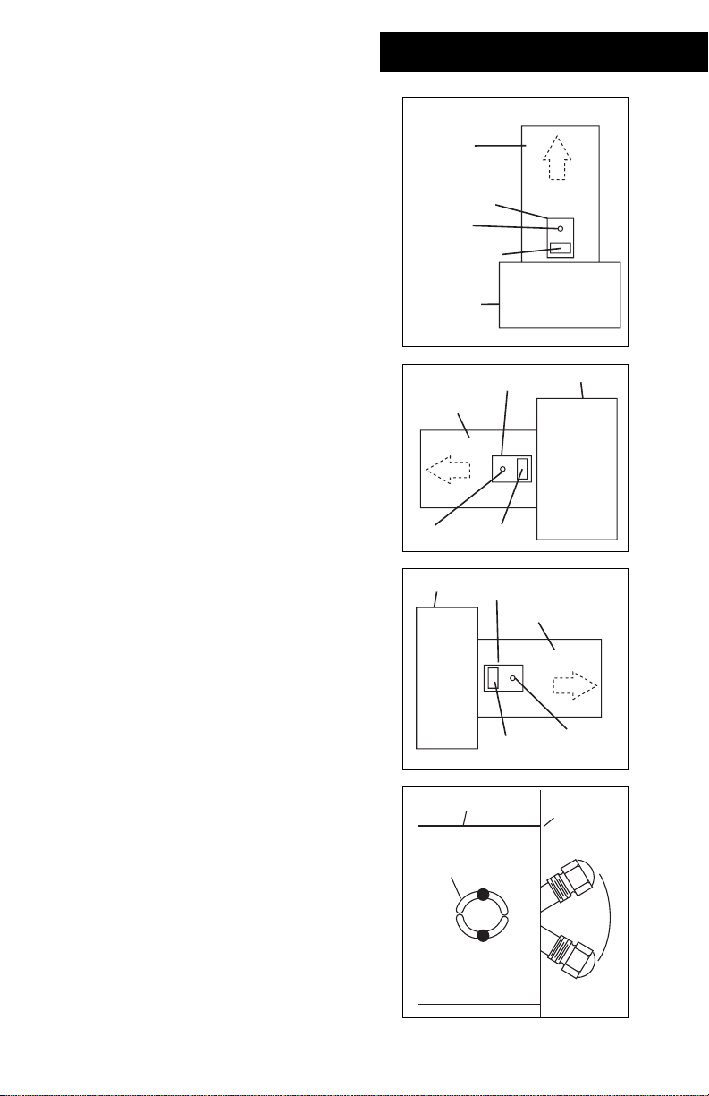
Selecting a Location for the Unit
When selecting a location for the installation
of your humidifier, certain conditions must be
met for its proper operation. The
recommended location for this humidifier is
on the supply plenum, approximately 3”
downstream of the furnace. In narrow
plenum arrangements, the humidifier should
be mounted on the narrow side of the duct.
Select a location so that the spray from the
nozzle will not impinge on the furnace fan,
control switches, air conditioning or heat
coils.
The humidifier should be mounted so that
the furnace air carries the mist away from the
humidifier thermostat. The unit is specially
designed to allow the nozzle to be adjusted
so that the thermostat can be located
upstream from the nozzle. For plenum
mounting, the nozzle should always be
pointed in the up position. When the position
of the nozzle has been determined, tighten
the nozzle/solenoid valve mounting hardware
securely.
Installation
DO NOT install the humidifier where freezing
conditions could occur or where accidental
overflow could cause water damage to the
home or property.
DO NOT install the humidifier where the
temperature will exceed 180° F. Excessive heat
may cause softening and distortion of the
plastic housing.
The installation of a water filter may reduce
the potential clogging of the nozzle and
solenoid valve in hard water applications
.
Supply
Plenum
Humidifier
Nozzle
Thermostat
Furnace
Humidifier
Supply Plenum
Thermostat
Nozzle
Furnace
Furnace
Nozzle/Solenoid
Mounting
Hardware
Humidifier
Thermostat
Humidifier
Supply Plenum
Nozzle
Supply
Plenum
Nozzle
 Loading...