

Page 1

Thank you for using our products, please contact us with any questions or needs.
This manual is for RT2418 series switches. It is a network management type PoE switch. You can log in to
the computer to configure the switch related functions. It can also be used as a normal switch without any
configuration. It will be updated subjected to product's updating new version will be not noticed specifically.
If this manual's any products description not accord with the real products, please in kind prevail.
Statement
① Please connect all the computers or network PoE devices to the switch before connecting the power cable.
② Connect the one end of the power cable to the switch and the power plug to the AC power outlet.
③ Power on the device connected to the switch. The corresponding indicator will light up. The installation
is complete.
使用产品前请仔细阅读本手册,并妥善保管。
相关工具以及产品相关文档请见“www.herospeed.net”
Installation Precautions
Please install it in a well-ventilated room. Do not block the vents of the equipment.
Do not place and install the switch in direct sunlight or near a heating device. Allow enough space
(more than 10cm) to allow the device to dissipate heat properly.
Do not install the device in a place exposed to moisture, dust, or soot.
Please keep the equipment horizontally installed or installed in a stable place, and take care to prevent
the product from falling.
Do not place heavy objects on the device.
Do not dribble or spill liquid on the device, and ensure that no liquid filled items can be placed on the
device to prevent liquid from flowing into the device.
The interface cables of the device must be routed indoors and outdoors cables must not be routed to
prevent overvoltage and overcurrent caused by lightning.
Please use the power cable supplied with the product. Do not use other non-supported products.
The grid voltage must meet the input voltage range of the dedicated power.
Do not disassemble the device at will.
Please transport, use and store the equipment within the allowable humidity and temperature range.
To ensure the normal operation and service life of the switch, observe the following precautions.
Connection Cable
3
Packing List
Open the box, there should be some accessories inside the box:
RT2418 series switches - 1 sets
Dedicated power cord (conventional national power cord) *1
Quick Operation Guide*1
If you find any damage or shortage of parts, please contact your local dealer or seller.
RT2418 Series
Managed Optical Fiber PoE Switch
Quick Start Guide
① Set the IP address of the login computer to the same network segment as the switch.
② Enter the switch IP in the computer browser → "Enter" to enter the switch login interface, enter the switch
user name and password, and click "Login".
NOTE: The switch IP address default is "192.168.2.1". The username default is "admin" and the password
default is "admin".
③ Enter the functions of the administrator, power supply, VLAN, port count, network, and backup interfaces
of the PoE switch.
Switch Configuration
Page 2
2
Specifications
RT2418 Series Description
Power Adapter Voltage Inpu t 100-240V/AC 50/60Hz
The maximum power supply
machine
440W
Lightning protection
Mould:+/ -4KV
Differential mode:+/-2KV
1~24 port: :10/100Mbps Po E Ethernet port
25~28 port:10/100/1000Mbps WAN1~WAN4 port
Transmission Distance 1~24 port: Recommended distance is 100m
Transmission Medium Cat5/5e/6 standard network cable / Fiber
IEEE802.3/10BASE-T Eth er
net
IEEE802.3u/100BASE-TX Ethernet
IEEE802.3ab 1000BASE-T Ethernet
Maximum F rame Size 1536 Bytes
MAC address list 2K
PoE Stand ard IEEE802.3af/at
PoE P ower Supply Type End-Span (4/5+;7/8-)
PoE P ower Con sumption at, (every port)
PoE: 24 green light indicates that the PoE is power on;
Ethernet: 24 yellow light ind icates that the Ethernet Link an d Act;
Working temperature 0℃~55℃
Storage temperature -40℃~85℃
Worki
ng
Humidity
0%-90% non-c onden sing
Storage Humidity 0%-95% RH non -condensing
Dimension (L x W x H) mm 441*300*44
Material SECC
Color Dark gray
Stability MTBF >30000h
Mechan ical
Protection level
Network Switch
Network Stand ard
Power Over Ethernet
LED Status In dicator PoE Ethernet
Environmental
Item
Power
Network Connector
Network Port
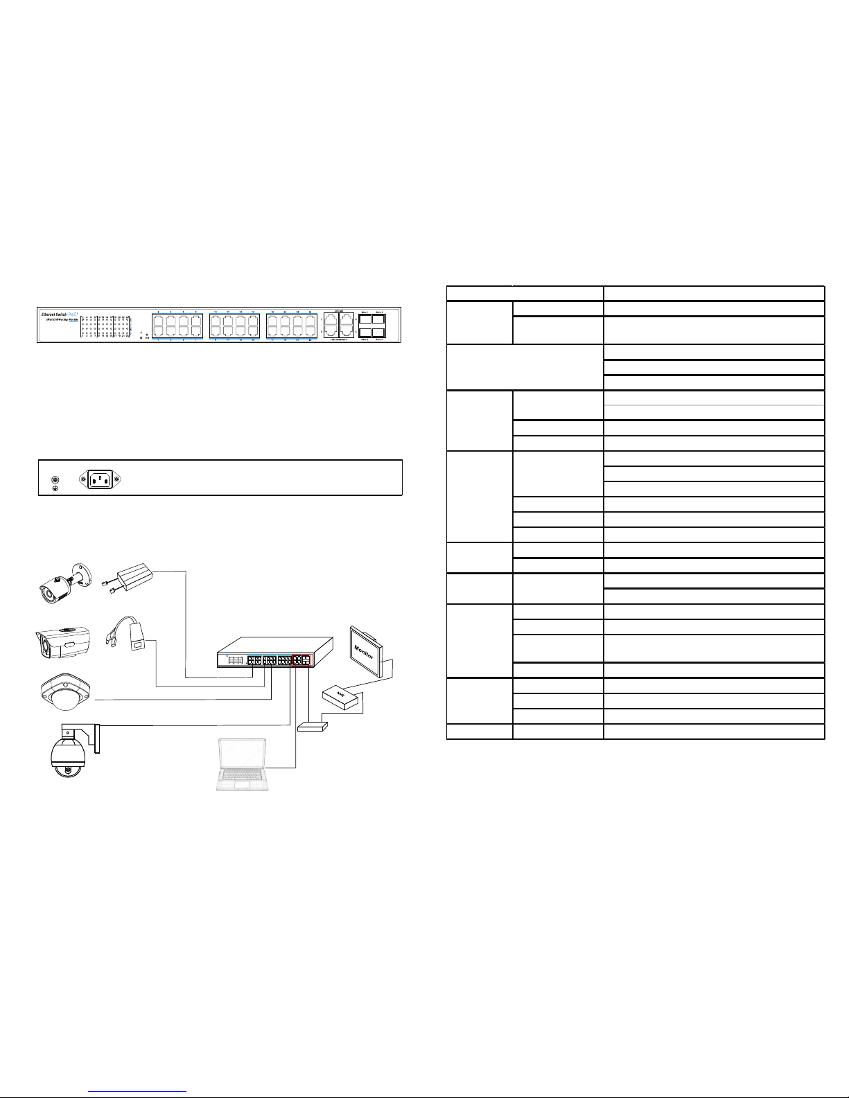
RT2418 Series Front Panel
◆ The front panel has 28 network ports and 4 fiber ports:
1~24 ports: 10/100Mbps PoE Ethernet ports;
25~28 ports: WAN1~WAN4 port: 10/100M/1000Mbps Uplink Ethernet port;
Gbic1~Gbic4 ports: Fiber1~Fiber4 port.
◆ LED status indicator:
1~24 ports indicator green: The switch provides PoE power.
1~24 ports indicator orange: The switch only accesses Ethernet.
RT2418 Series Rear Panel
◆ The rear panel has a power connector:
100~240V 50/60Hz AC power supply.
Product appearance description
1
Note: When connecting 1 (Gigabit Ethernet port) and 2 (fiber optic) in the above figure,
please follow the "two-choice principle".
Installation application diagram
100-240V~50/60Hz
PoE Splitter
Camera
Cat5/5e/6
Cat5/5e/6
PoE Splitter
IP Camera (PoE)
Camera
24+4+4 Ch PoE Switch
Media Converter
Video Line
IP Camera (PoE)
Init
9 11
13
15
10 12
14
16
17
19
21
20
22
24
23
18
1
3 5
7
2
4
6
8
UPLINK
100/1000Base-T
Gbic 1
Gbic 3
Gbic 2
Gbic 4
1
3
4
2
17
19
2123
2
10
18
3 9
11
13
15
4
12 20
5
6
14
22
7
8
16
24
LI
N
K
LINK
POE
POE
1
Ethernet Switch
24Port10/100+4 Por t Gig a 4Po rt Gb ic
+
1
2
 Loading...