

Page 1
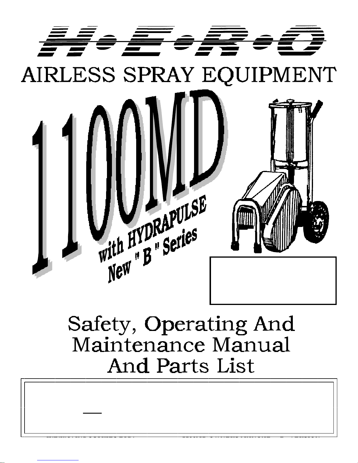
NEW For 1997.
Hydrapulse “B” Version.
Starting with serial
DO NOT attempt to operate this machine until you have read and understand
ALL safety precautions and operating instructions.
H.E.R.O. INDUSTRIES LTD. 1100MD OWNERS MANUAL - “B” VERSION
39
Page 2
H.E.R.O. WARRANTY
H.E.R.O. INDUSTRIES LTD., guarantees this airless pump to be free of
defects in materials and workmanship to the original owner, for a period of
one full year from the date of purchase.
The warranty entitles the owner to parts replacement at no charge. The
parts replacement warranty is valid for any necessary replacement, whither
caused by material or workmanship defect or simple wear. The hydrapulse
membrane (part# 4-04-22-4500) is warranted for LIFE. Installation costs
for the hydrapulse membrane is provided for the first 12 months only. H.E.
R.O. Industries Ltd. offers no warranty on the intake ball, outgo ball, drive
belt, hoses, gun or accessories, plastic, rubber, other soft goods or motor
used in or supplied with the H.E.R.O. sprayer.
Motor, accessories, etc., which are supplied by other manufacturers and are
attached to or supplied with the H.E.R.O. airless pump, are warranted only
to the extent that these parts are warranted by their respective
manufacturers. Warranty claims must be made directly to such
manufacturers or their local authorized service depots.
The warranty is only applicable to the original purchaser and the equipment
has been properly used, operated and maintained in accordance with all
instructions, precautions and warnings contained in this manual. For the
purpose of this warranty, damage resulting from accident, abuse, improper
cleaning or operation, fire, flood, or Act of God, is not covered.
H.E.R.O.’s liability is limited to replacing parts found to be defective or
worn and does not include; transportation costs, damage or other expenses
of any kind incurred in connection with the purchase and use of this
sprayer.
Repairs claimed under warranty must be performed at an authorized H.E.R.
O. Service Center, using only genuine H.E.R.O. parts. Parts necessary
under warranty claim will be supplied by your local H.E.R.O. Service
Center.
DO NOT return worn parts to factory without authorization.
To qualify for the warranty, the warranty card (attached to this page)
supplied with this H.E.R.O. airless pump, must be completed with
H.E.R.O. INDUSTRIES LTD. 1100MD OWNERS MANUAL - “B” VERSION
1
Page 3

TABLE OF CONTENTS
emoving of any part, shut off power and relieve pressure.
For greatest user satisfaction, please familiarize
yourself with all maintenance and operational instructions
Important Safety Precautions ..............................................................................................3-4
Introduction ...........................................................................................................................5
Operating Instructions ...........................................................................................................5
Setting Up To Spray ..............................................................................................................6
Flushing The Unit .................................................................................................................7
Special Notes ........................................................................................................................8
Airless Spray Painting Suggestions ...................................................................................9-11
Trouble Shooting ............................................................................................................12-19
Hydrapulse Membrane Replacement ...................................................................................20
Intake Seat Replacement ......................................................................................................21
Outgo Valve ........................................................................................................................22
Piston Repairs ................................................................................................................23-24
Pressure Control Valve Repairs ...........................................................................................25
Accessories .........................................................................................................................26
Parts List And Descriptions ............................................................................................27-31
Exploded Unit Diagram ..................................................................................................32-33
Parts Depot List ..............................................................................................................34-37
IMPORTANT
NOTE: AS WITH ALL MECHANICAL EQUIPMENT, PROPER OPERATING AND
MAINTENANCE PROCEDURES ARE REQUIRED TO KEEP YOUR H.E.R.O. AIRLESS
PUMP PERFORMING TO YOUR SATISFACTION. THE FOLLOWING SAFETY,
OPERATING AND MAINTENANCE INSTRUCTIONS ARE IMPORTANT.
Read and understand this manual completely, especially with regard to all safety precautions. Read
and follow instructions on all warning labels on your equipment. Keep the warning labels clean and
readable at all times. Order new labels from your local distributor or from H.E.R.O. Industries Ltd. if
needed.
The manufacturer shall not be responsible for any loss, damages, or injury of any kind or nature
whatsoever resulting from the use the equipment other than in strict compliance with the instructions,
cautions and warnings contained in this operating and instruction manual and as displayed on the face
of the equipment.
This system is capable of producing 2400 psi. ( spray pressure ). To avoid rupture and injury DO
NOT operate this pump with components rated less than 3000 psi. working pressure (including but
not limited to spray guns, hose and connections).
Before servicing, cleaning or r
H.E.R.O. INDUSTRIES LTD. 1100MD OWNERS MANUAL - “B” VERSION
2
Page 4

IMPORTANT SAFETY PRECAUTIONS
WARNING
NEVER PLACE FINGERS NEAR SPRAY TIP OF GUN. NEVER POINT GUN TOWARD
ANY PART OF YOUR BODY, OR THAT OF ANY OTHER PERSON. MATERIAL ISSUING
FROM THE SPRAY TIP IS AT HIGH PRESSURE. IF FINGERS, OR ANY PART OF THE
BODY ARE PLACED NEAR THE TIP OF THE SPRAY GUN, IT IS POSSIBLE THAT THE
SPRAY COULD BREAK THE SKIN AND INJECT SOME OF THE SPRAY MATERIAL. IF
INJURY DOES OCCUR, SEEK THE IMMEDIATE ATTENTION OF A MEDICAL DOCTOR.
BE PREPARED TO INFORM THE DOCTOR WHAT FLUID WAS INJECTED, IF THE
INJURY IS OF AN INJECTION NATURE. EQUIPMENT AND CHEMICALS WHEN USED
IMPROPERLY CAN BE DANGEROUS!
ý NEVER place any part of the body in front of the spray tip or aim the gun toward any part of the
body.
ý NEVER point the gun toward any individual.
ý NEVER treat any injury as a simple cut. If injury does occur, seek immediate medical attention. Be
prepared to inform the doctor what fluid was injected.
ý NEVER allow another person to use the sprayer unless he is thoroughly instructed on its
operation and has read all safety precautions in this manual and all safety warning labels attached to
unit.
ý NEVER use around children.
ý NEVER attempt to perform any maintenance or service on any part of the unit spray system
without first;
1. Shutting off the unit.
2. Disconnecting the power cord from the outlet.
3. Relieving all pressure in the pump by triggering the gun.
4. Locking gun trigger in "LOCKED" position, with gun locked closed.
ý NEVER operate the sprayer without the tip guard complete and in place.
ý NEVER spray any material in the vicinity of open flame, pilot lights, electrical outlets or any
other source of ignition.
ý NEVER spray volatile materials with flash points lower than 140 F (60 C).
ý NEVER attempt to stop any leakage in the paint line or at any fitting with your hand or any part of
your body. Immediately shut off the unit should leakage occur.
ý NEVER wash an electric motor, nor operate it in the rain or in wet or damp areas, to protect
yourself from electric shock.
ý NEVER allow paint hose to become kinked, or to vibrate against rough or sharp surfaces.
ý NEVER operate the unit at pressures higher than the pressure rating of the lowest rated
component in the system, or at pressure higher than factory preset.
ý NEVER spray in an enclosed area. The spraying area must be well ventilated to safely remove
chemical vapors.
ý NEVER operate the unit with worn or damaged accessories, or with accessories other than those
supplied by H.E.R.O. Industries, unless the accessories have been first specifically approved in
writing by H.E.R.O. Industries Ltd.
ý NEVER allow the unit to be serviced or repaired anywhere other than an authorized H.E.R.O.
Service Center, or with other than genuine H.E.R.O. parts or components.
ý NEVER leave unit unattended without first shutting off, triggering the gun to relieve all pump
pressure, and setting the trigger lock on gun in "LOCKED" position, with gun locked closed.
H.E.R.O. INDUSTRIES LTD. 1100MD OWNERS MANUAL - “B” VERSION
3
Page 5

ALWAYS
þ ALWAYS follow H.E.R.O. recommendations for operation and safety completely.
þ ALWAYS ensure that switch is in off position before plugging in the electric motor.
þ ALWAYS set trigger lock on gun in "LOCKED" position when not in use, with gun locked close.
þ ALWAYS check connections and fittings for tightness before operating the unit.
þ ALWAYS locate the unit in a well ventilated area a minimum of 25 feet from the spray area.
þ ALWAYS ground the unit, the paint containers, and the object being sprayed to eliminate static
discharge. Ensure that all these objects remain grounded throughout the entire spraying operation.
þ ALWAYS use approved 3 prong grounded extension cord and approved grounded outlets of the
voltage and frequency specified on the motor. The outlet must be at least 25 feet from the spraying
area.
þ ALWAYS use approved 3 prong grounded extension cord not less than # 12/3 gauge up to 50 feet,
and not less than # 10/3 gauge up to 100 feet. DO NOT exceed 100 feet of extension cord.
þ ALWAYS use accessories and components approved for at least 3000 psi (working pressure) in the
spraying system.
þ ALWAYS use accessories and components supplied by H.E.R.O. Industries Ltd., or specifically
approved in writing by H.E.R.O. Industries Ltd. on with the unit.
þ ALWAYS examine accessories for wear or damage before operating the unit.
þ ALWAYS use lowest possible pressure when flushing and cleaning the unit, and hold the gun firmly
against a metal container to reduce static discharge possibility.
þ ALWAYS wear a face filter mask when operating the unit.
þ ALWAYS ;
1. Turn off the motor.
2. Disconnect the power cord from the outlet.
3. Relieve all pressure in the pump by triggering the gun.
4. Lock gun trigger in "LOCKED" position, with gun locked closed before attempting to perform
any maintenance or service on any part of the unit spray system.
þ ALWAYS wear safety glasses when operating the unit.
þ ALWAYS ensure fire extinguishing equipment is readily available and properly maintained in the spray
area.
þ ALWAYS observe good housekeeping and keep the spray area free from obstructions.
þ ALWAYS be aware that certain chemicals may react with aluminum, carbide, or other components in
the pump system. Read the manufacturer's label on all materials to be sprayed, and follow the
manufacturer's recommendations. If in doubt, consult your material sup plier to be sure.
þ ALWAYS replace any damaged airless paint hose. A scratched, torn, cut or otherwise damaged outer
core of the paint hose can lead to a rupture. DO NOT attempt to repair a damaged hose.
H.E.R.O. INDUSTRIES LTD. 1100MD OWNERS MANUAL - “B” VERSION
4
Page 6
H.E.R.O. AIRLESS SPRAY PAINTING
Welcome to the world of H.E.R.O. airless paint spraying. We are sure you will enjoy owning and operating
your new H.E.R.O. model 1100MD. With H.E.R.O. airless spray equipment you will avoid the
inconvenience and mess of overspray. You are spraying paint, not air, and the paint is driven to the painting
surface in a clean, fan shaped spray which penetrates all cracks and corners. To attain these results, you must
adjust the pressure as low as possible. We recommend that you become familiar with your H.E.R.O. unit.
Discuss with your dealer the useful accessory items he has to offer - various types of tips, extension poles for
hard to reach areas, extra hose, etc. Use of accessory items is often the difference between a good job and an
excellent one!
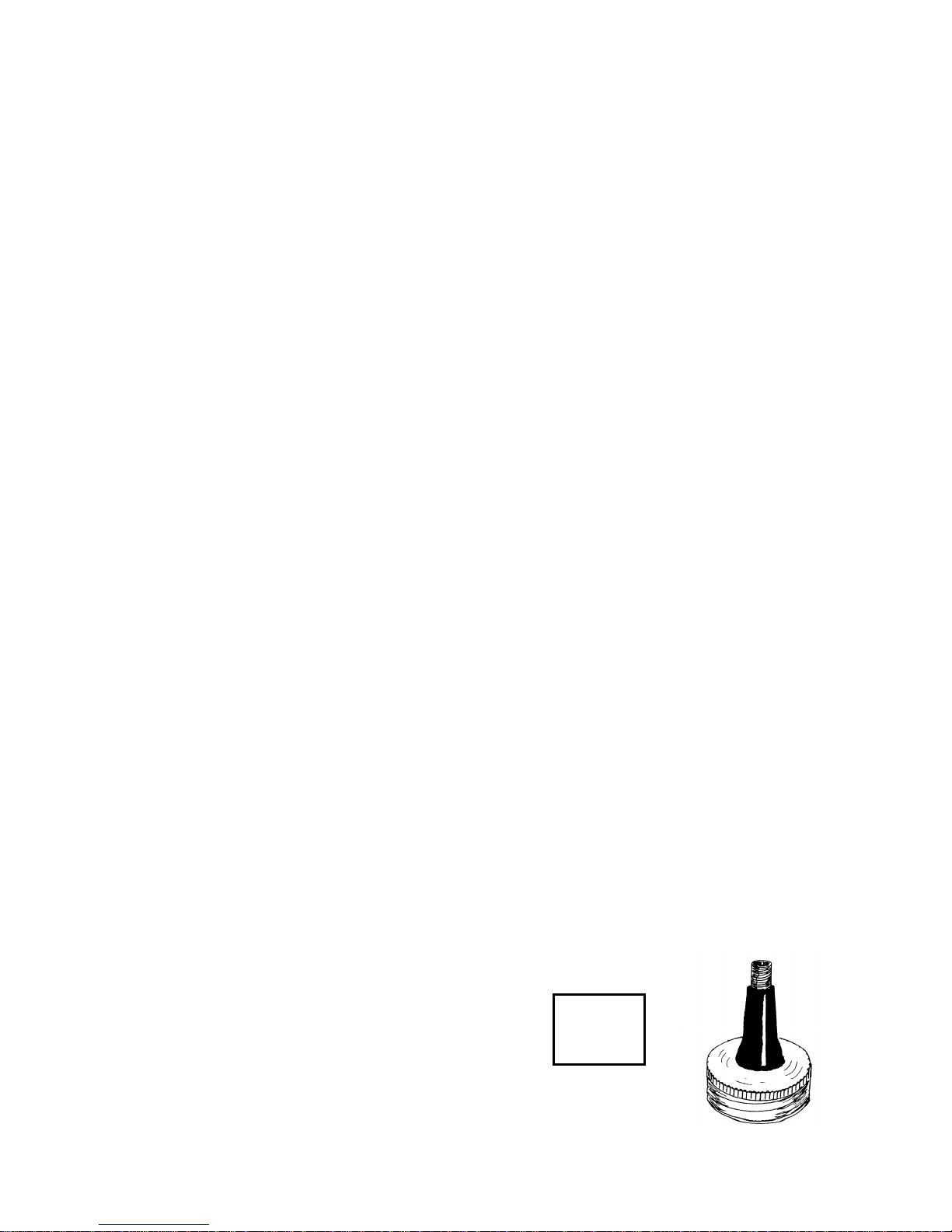
NEW 1997
“B” SERIES
HYDRAPULSE
INTAKE
ASSEMBLY
BEGINNING WITH
SERIAL NUMBER
190031
OPERATING INSTRUCTIONS
WARNING
Do not attempt to operate this machine until you have read and understood all safety precautions and
operating instructions. Equipment and chemicals when used improperly can be dangerous.
Your H.E.R.O. airless sprayer has been fully factory tested prior to shipment.
BEFORE STARTING YOUR H.E.R.O. PUMP....
CHECK to ensure that the shipping seal has been removed from under the cap on the hydraulic tank.
Hydraulic tank should be at least 3/4 full of H.E.R.O. LVO hydraulic fluid.
CHECK all fittings and connections in the pump system, hose, and gun to ensure that they are tight.
CHECK to ensure that there is a spray tip in the gun, and that the tip is the correct size for the coating you
are to spray. ( There are various tips available, for each type of coating or configuration. See " Airless Spray
Tip " on page 11 , for proper tip selection.
CHECK to ensure that you have H.E.R.O. strainer bags, H.E.R.O. Wonder Wash, appropriate thinner for
the paint, a waste container, and any other accessories you may require for the job.
CHECK to ensure that you have adequate extension cord size and length if the machine cannot be situated
immediately next to an electric outlet. Distances up to 50 feet require #12/3 wire grounded cord, up to 100
feet require #10/3 wire grounded cord. DO NOT exceed 100 feet of extension cord. If distance is greater,
obtain and install extra length of H.E.R.O. airless spray hose.
READ THIS MANUAL THOROUGHLY.
H.E.R.O. INDUSTRIES LTD. 1100MD OWNERS MANUAL - “B” VERSION
5
Page 7
SETTING UP TO SPRAY
1. Remove unit from shipping carton.
2. Remove shipping seal from under hydraulic tank cap.
3. Re-position paint tank lid knob from the shipping position, on the underside
of lid, and place on the lid top.
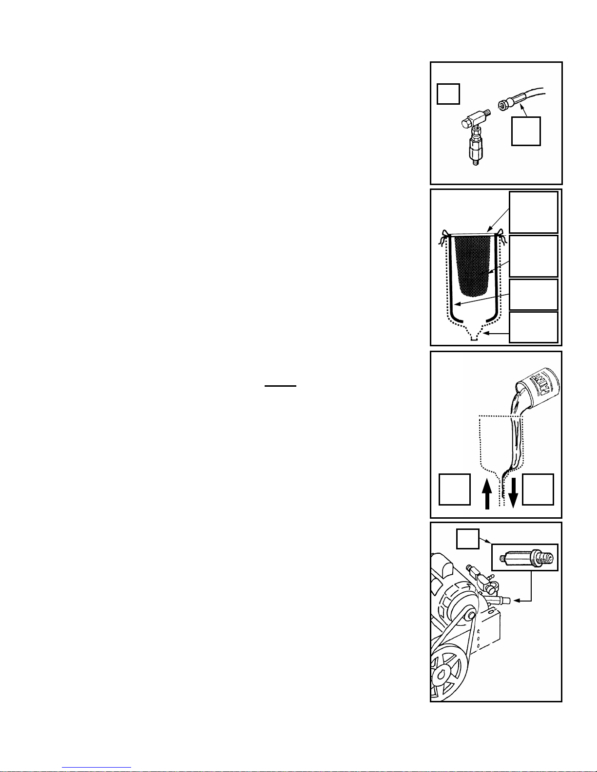
4. Attach paint hose to outgo tee (ref# 43) and gun to paint hose.
NOTE; Spray tip and tip guard should be attached to gun prior to attaching
to hose.
5. To assist in clean up, use and install paint tank plastic liners ( accessory item
5 GAL PL ). Line the inner sides of tank, ensuring that the liner does not
block the tank screen in the bottom of the tank. Fold excess over the outside
of tank.
6. Install strainer bag (accessory item 5GAL SB) in tank and secure with large
rubber band ( accessory item 106 ).
NOTE; Strainer bag must remain 4 inches from the bottom of tank.
7. Trigger gun to release any pressure in the unit. Use extreme caution to ensure
that the gun is not directed towards anyone or any object which may be
damaged.
NOTE; Unit may contain storage solu tion.
8. To remove storage solution, add one gallon of thinner, compatible with the
type of paint to be used, to the paint tank.
9. Turn pressure control knob (ref# 71) to lowest pressure setting.
10. Be sure motor switch is in "OFF" position. Plug unit into 115V, 15 amp.,
grounded circuit.
NOTE; If using an extension cord, you MUST use a #12/3 wire grounded
cord, up to 50 feet or #10/3 wire grounded cord, up to 100 feet. DO NOT
EXCEED 100 FEET OF EXTENSION CORD. If distance is greater,
purchase and install additional lengths of airless spray hose.
11. Turn motor switch "on" and increase pressure slowly. Trigger gun into a
waste container. Continue spraying until pump runs dry and all thinner and
holding solution has been removed. Keep pressure low.
12. Pour paint through strainer bag into paint tank.
NOTE; Pour paint (particularly thick paints ) slowly, to allow paint to
enter the intake hose while at the same time allowing air the opportunity to
escape up the intake tube. Pouring paint in quickly can trap air in the intake
tube ( air lock ) and make priming difficult.
13. Replace paint tank lid. Keep tank covered at all times to prevent
contaminates from falling into the paint.
14. Increase the pressure, slowly at first, by turning the pressure control knob
clockwise. Spray a test pattern.
NOTE; Begin by spraying a test pattern onto old newspaper or other scrap
material. Continue increasing the pressure until the spray pattern is
uniformed from top to bottom, with no heavy areas. Secure pressure control
setting, by turning the silver lock ring (ref# 73) counter clockwise until
snugly against the face of the pressure control knob. If heavy areas are still
visible at maximum pressure setting, thin the paint with the correct thinner,
according to the paint manufacturer's recommendations.
43
Air
out
Paint
Rubber
band
106
Strainer
bag
5GAL SB
Liner
5GAL PL
Tank
outline
Paint
in
70
H.E.R.O. INDUSTRIES LTD. 1100MD OWNERS MANUAL - “B” VERSION
6
Page 8
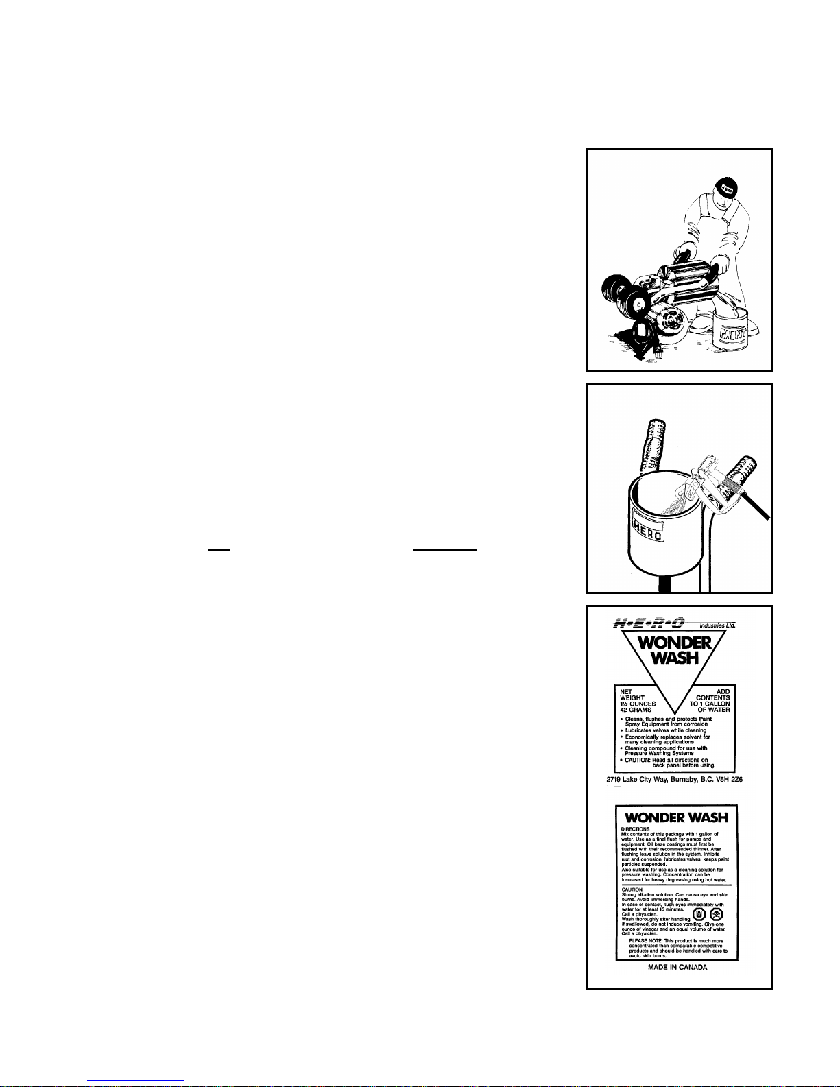
FLUSHING THE UNIT AT SHUTDOWN
OR COLOR CHANGE
If shutting down for a short period of time, it is sufficient to trigger the gun to
relieve pressure. Then set the safety lock on gun to "locked" position with the
gun locked closed and immerse the gun in a container of the correct thinner for
the paint you are spraying.
If shutting down at job completion, for the night, or to change colors;
1. Turn pressure control knob counter clockwise to low pressure setting.
2. Switch unit “OFF”. Remove spray tip from gun and trigger gun back into
paint tank. Direct against side of tank.
3. Remove and discard strainer bag.
4. To remove any remaining paint from the paint tank, tip unit as shown and
pour into original container. Allow plastic liner to fall into container. Remove
and discard liner.
5. Upright unit and add one(1) gallon of the correct thinner, for the paint being
used, to the paint tank.
6. Re-start unit and trigger gun back into the paint tank. Direct against the sides
of the tank. Use the stream to clean the sides and bottom. Circulate the thinner
for several minutes.
7. Remove dirty thinner, per step 4 and repeat steps 5 & 6 with fresh thinner.
Trigger gun into waste container until tank runs dry.
8. Repeat procedure using a gallon of pre-mixed H.E.R.O. Equipment Wonder
Wash solution. If not using Wonder Wash, unit must not be stored with
water. Only store with a non corrosive material ( Paint thinner, solvent ).
9. Switch unit "off" and trigger gun to relieve remaining pressure.
10. Remove and rinse gun handle filter in correct thinner.
SPECIAL STORAGE INSTRUCTIONS
In areas where the sprayer is NOT used 12 months of the year, special preparations
must be used for winter or off season storage. Because solvents evaporate quickly,
they should not be used for long term storage. A petroleum based solution ( solvent
and oil ) should be used as an extended storage material. DO NOT allow storage
solution to freeze in the sprayer.
H.E.R.O. Equipment Wonder Wash, available from your H.E .R.O. distributor,
will provide the added cleaning benefits of solvent at a much lower cost. Suitable
as a short term ( 1-2 days ) storage solution only
H.E.R.O. INDUSTRIES LTD. 1100MD OWNERS MANUAL - “B” VERSION
7
Page 9

SPECIAL NOTES AND
se = 3 of 50’ x 1/4” paint hose and 2 of 50’ x 3/8 paint hose.
3 of 50’ x 1/4” paint hose and 3 of 50’ x 3/8 paint hose.
GENERAL MAINTENANCE INSTRUCTIONS
NEVER LEAVE THE UNIT UNDER PRESSURE WHEN NOT SPRAYING (MOTOR TURNED
OFF). RELIEVE PRESSURE BY TRIGGERING GUN. NEVER STORE THE UNIT WITH PAINT
OR WATER IN THE PUMP SYSTEM, EVEN OVERNIGHT.
ý NEVER attempt to start the motor when the unit is under pressure. Relieve pressure and follow
instructions in "Setting up to spray"
ý NEVER attempt to run the motor on longer or lighter extension cord than specified.
ý Avoid operating the unit while tilted. Keeping it level assures greater operating efficiency.
þ If motor's thermal overload switch has opened, unplug unit and allow it to cool.
ý DO NOT attempt to resume spraying before determining and correcting the cause of overheating.
þ Always follow flushing and cleaning instructions exactly.
þ In hot weather, locate unit in shade.
þ Regularly check the level of H.E.R.O. LVO hydraulic fluid in the hydraulic tank. It should be kept near
full, top up as needed with only genuine H.E.R.O. LVO hydraulic fluid.
þ Crankshaft eccentric bearing should be greased at regular intervals consistent with hours of use. Use
MO-2 grease (i.e. common auto grease) approximately every 10 hours of operation.
þ Check drive belt ( part# 66/100 ) tension frequently. The belt will stretch with use, and should be
adjusted after 20 hours of operation and again after 50 hours. Periodic checks after 50 hours should be
made. A slipping belt will reduce sprayer performance and the tension should be checked frequently.
þ Regularly check fittings, bolts, nuts and connections for damage. Tighten, adjust or replace as required.
þ Check crankshaft alignment often. An out of alignment crankshaft will cause the damage to the
eccentric bearing.
þ If you wis h to power your H.E.R.O. airless sprayer with a generator, it must be a minimum of a 5000
watt generator, in good operating condition.
NOTE; An electric tool must be powered by a generator which has an output wattage of at least three
times the maximum draw of the motor under full load.
þ A minimum 50’ and a maximum of 300’ of airless spray hose may be used.
NOTE: 50’ x 3/8” paint hose ( part # 117 ) should be used for every 50’ x 1/4” paint hose
( part # 114 ) over 100’.
100’ total length of paint hose = 2 of 50’ x 1/4” paint hose.
150’ total length of paint hose = 2 of 50’ x 1/4” paint hose and 1 of 50’ x 3/8 paint hose.
200’ total length of paint hose = 2 of 50’ x 1/4” paint hose and 2 of 50’ x 3/8 paint hose.
250’ total length of paint ho
300’ total length of paint hose =
þ Product viscosity, altitude ( feet above sea level ) and vertical reach can effect pump performance and
special accessories may be required. Product viscosity may have to be further reduced at higher
elevations. The larger diameter 3/8” paint hose should also be used, to aid in the movement of spray
materials.
H.E.R.O. INDUSTRIES LTD. 1100MD OWNERS MANUAL - “B” VERSION
8
Page 10

AIRLESS SPRAY PAINTING
SUGGESTIONS AND TECHNIQUE
A good airless spray application is the result of many factors. Surface preparation, which includes cleaning
and degreasing, priming, material compatibility, quality finish product and correct applicatio n technique. All
are all important to the finished results.
The key to all good applications is a good spray gun technique. The finished results are what the client will
look at and base his opinion on. Your skill and abilities are as important as good equipment and good paint.
Proper application techniques can easily be learned by using the following simple guidelines. If you are not
familiar with the basic spray techniques we recommend that you study this portion of the manual and
practice the technique s shown. Practice your technique on scrap cardboard or old newspaper until you feel
confident.
FOR EXCELLENT RESULTS, READ AND PRACTICE THESE TECHNIQUES
1. Always strain all paint through a H.E.R.O. strainer bag.
The most common reason for airless sprayers to malfunction is foreign matter jamming the valves or
plugging the tip. Always strain the paint before putting through the pump.
2. Always spray at the lowest pressure setting which will provide a uniform spray fan. (fig. 1, page 10)
Adjust pressure control knob so that paint is completely atomized . Insufficient pressure will result in
"tailing". Too much pressure will result in excess fog and over spray, excess tip wear, and increased
sprayer wear and tear. See setting up to spray, page 5.
3. Always spray at right angles to the surface being sprayed. (fig. 2, page 10)
Angling or arcing the nozzle toward the surface will cause uneven coverage and excessive
overspray.
4. Always hold spray gun 12-15 inches from spray surface. (fig. 3, page 10)
Too close and the fan width will be reduced and material will be applied too heavily (runs).
Too far from the surface and you will have excessive overspray and light coverage (transparent).
5. Always move the gun parallel to the surface being sprayed, at a consistent speed.
This avoids uneven coverage (thick or thin areas).
6. Always start the spray stroke before trigge ring the gun and release the trigger before completing the
stroke. (fig. 4, page 10)
This avoids heavy build up of paint at either end of the spray stroke.
7. Always lap your spray pattern by one half. (fig. 5, page 10)
This assures full coverage of the surface being painted.
H.E.R.O. INDUSTRIES LTD. 1100MD OWNERS MANUAL - “B” VERSION
9
Page 11
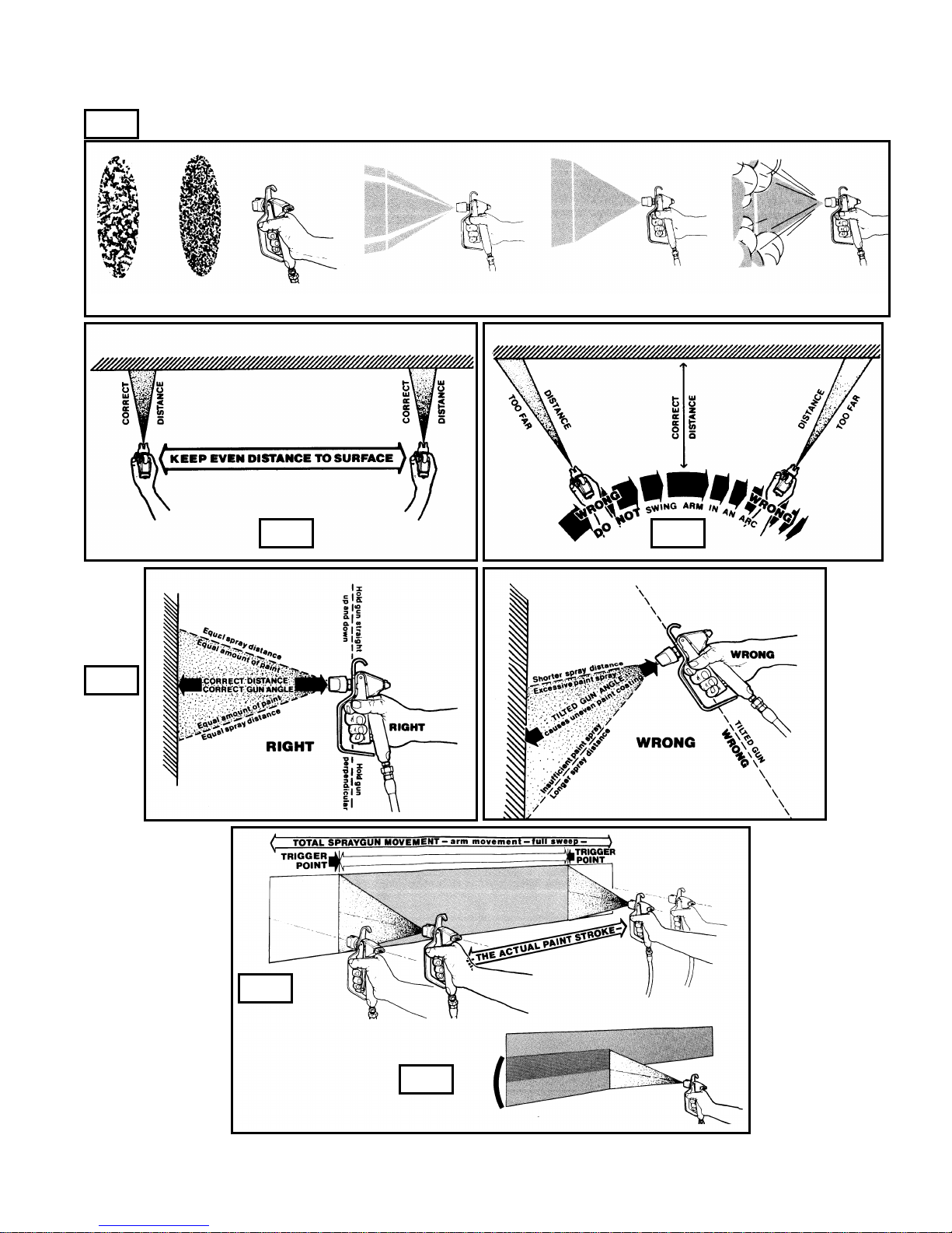
AIRLESS SPRAY PAINTING
SUGGESTIONS AND TECHNIQUE
FIG.
Poor Good Tailing Good Pattern Fog, Overspray
FIG.
FIG. FIG.
FIG.
H.E.R.O. INDUSTRIES LTD. 1100MD OWNERS MANUAL - “B” VERSION
FIG.
10
Page 12

SPRAY TIP SELECTION
TIP SIZE FOR APPLICATION OF
.021 Exterior Latex on large unobstructed areas.(max. size allowed) ( 60 OZ. )
.018 Interior Latex, Exterior Latex, Shake Paint, Exterior Flat Paints. ( 46 OZ. )
.015 Alkyd Flat Enamel, Interior Latex, Semi-Gloss Enamel, Stains. ( 30 OZ. )
.013 Fine ground Gloss Enamels, and good quality Stains. ( 23 OZ. )
.011 Clear Varnishes and Lacquers. ( 15 OZ. )
.009 Clear Varnishes and Lacquers. ( 10 OZ. )
NOT: The above volumes achieved with gun wide open for 1 minute and pump spraying at
2000psi. All volumes are approximate. To test worn tips, spray water through the tip at 2000 psi.
for 1 minute. Spray into bucket and weigh amount (less weight of bucket). If it is substantially
greater than what is listed above, then the tip should be discarded or reclassified. As a tip wears, the
hole gets larger and the fan pattern becomes narrower.
ORIFICE SIZE
All tips are rated by the size of the orifice or bore size. The bore size is measured in tho usandths of an inch
( .018 = 18 thousandths of an inch ). The size of tip required is based on the consistency of the material to be
sprayed. The thicker the paint, the larger the tip size required. Always consult the product label or ask the
paint retailer for the manufacturer's recommendations with regard to proper tip sizes.
FAN WIDTH
Fan width or pattern width is determined by the spray tip's "fan width" classification. This size is measured in
inches, and is determined when spraying 12 inches from the spray surface. Various methods of noting the fan
widths are used by tip manufacturers. Ask your distributor for assistance.
NOTE: Two tips having the same tip size, but different fan widths will deliver the same amount of paint
over a different area (wider or narrower strip). A spray tip with a narrow pattern width makes it
easy to spray in tight places. Use only good quality, high-pressure tungsten carbide spray tips.
SPRAY TIP REPLACEMENT
During use, especially with Latex paint, high pressure and material abrasion will cause the orifice to grow
larger. As the orifice grows larger, the fan width grows smaller. Replace tips before they become excessively
worn. Worn tips waste paint, cause overspray, make cutting in difficult, and decrease sprayer performance.
NOTE: When using Latex paint, a spray tip will wear at the rate of one size for approximately every 100
gallons of material sprayed.
An excessively worn tip can be the cause of apparent operating problems with the unit. If a tip is worn
past the aperture size which the unit can support, pulsation will become evident in the spray fan/pattern.
Added strain is placed on the Hydrapulse membrane as it attempts to keep the spray pressure consistent.
When the tip wears beyond .031, its is releasing more material than the unit is bringing in. The natural
reserve of product in the paint chamber is reduced and harm to the membrane begins. ALWAYS check
your tips for wear when trouble shooting the equipment. The 1100MD can support up to a maximum of a
one .031 tip or two 021 tips.
H.E.R.O. INDUSTRIES LTD. 1100MD OWNERS MANUAL - “B” VERSION
11
Page 13
TROUBLESHOOTING
Hydraulic Energy Regulated Output (H.E.R.O.) is more than just our name, it is the bases for the
operation of the pump. It is the regulation or control, of hydraulic energy, which allows the equipment to
build and then deliver or have an output of pressure. Once you have a basic understanding of the operation of
the equipment and the effect created in one area and how it will effect operation in another area, you will be
better able to diagnose and make repairs.
All H.E.R.O. hydrapulse membrane pumps are made up of two (2) distinct pumps. The first, and most
important pump is the hydraulic pump. The hydraulic sys tem is made up of two valves, the hydraulic intake
valve (ref# 59) and the hydraulic outgo valve, known as the hydraulic pressur e control valve (ref# 70). The
second pump is known as the paint or material pump. The paint system is made up of two basic valves, the
paint intake valve assembly (ref# 16-28), paint outgo valve, (ref# 32). For correct operation, all four valves
must be in good working condition. For this manual we will refer to the two systems as "hydraulic" and
"paint".
At the center of these two pumps is the hydrapulse membrane. The hydrapulse membrane is a flexible nylon
disc which transfers the energy (pressure) created by the hydraulic pump, to create energy (pressure) in the
paint pump. The function of the hydrapulse membrane is to create a barrier between the hydraulic oil and the
spray material and transfer the energy created.
To fully understand and trouble shoot a H.E.R.O. pump, always keep in mind that "for every action,
there is an opposite or corresponding re-action". For every action of the hydraulic intake valve (ref# 59),
there is an opposite re-action of the hydraulic outgo valve (ref# 70). At the same time there are corresponding
re-actions taking place within the paint pump. This means that as the hydraulic intake valve is opening, so is
the corresponding paint intake valve, and while the hydraulic outgo valve is closing, so is the corresponding
paint outgo valve. The operation and function of each valve is discussed at the end of this section.
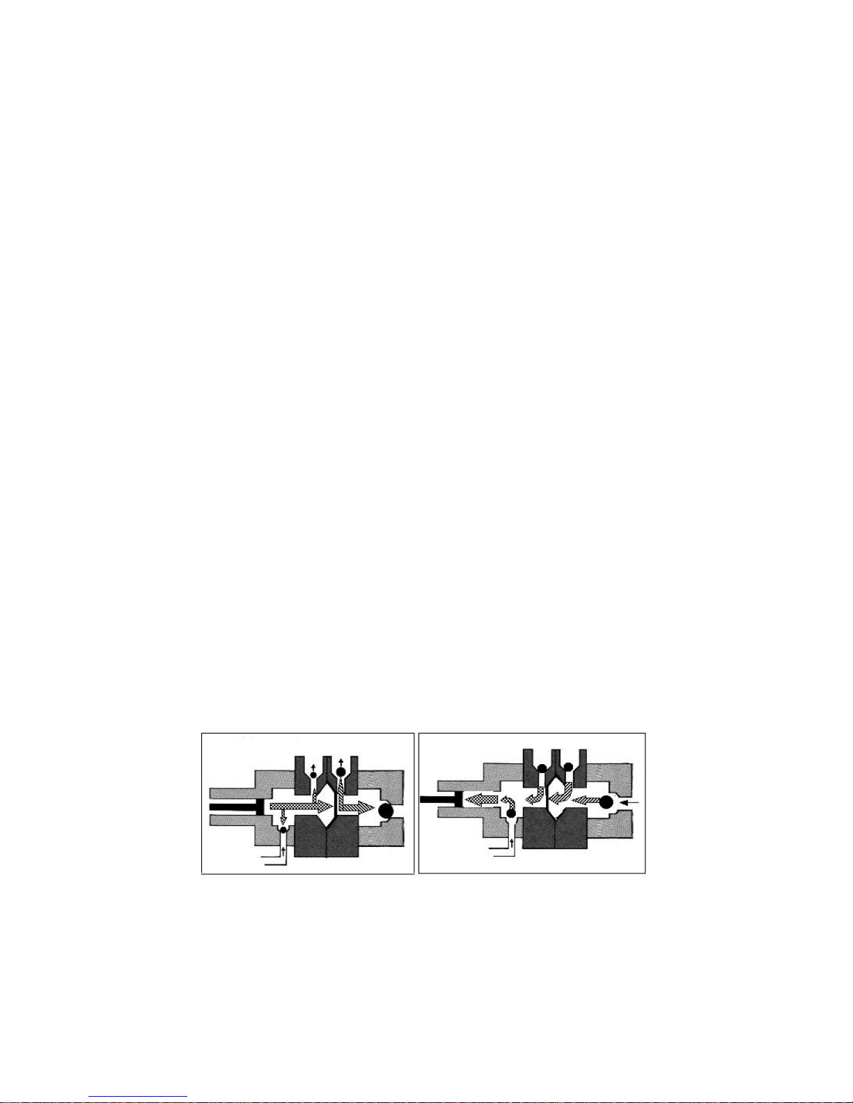
For correct operation to begin, the hydraulic system must be fully primed and all air must be removed
( see "purging" page 16 ). Operation begins with piston in the backward position (fig.# 2). At this point the
hydraulic intake is open, while the hydraulic outgo valve is closed. The corresponding paint valves are in
similar positions.
As the piston moves forward, it pushes hydraulic oil forward. This movement of oil causes the hydraulic
intake valve to close and the hydrapulse membrane to move forward (fig.# 1). The hydraulic outgo valve will
remain closed until sufficient pressure is created to cause it to open. While the hydraulic valves are operating
a corresponding re-action is taking place in the paint valves. The forward movement of the hydrapulse
membrane pushes the paint, causing the paint intake valve, (ref# 16-28) to close. The trapped paint requires a
means of release, so it forces the outgo valve, (ref# 32), to open and paint flows to the gun.
Fig. 1 Fig. 2
The backward movement of the piston, creates a vacuum in the hydraulic system. This causes the hydraulic
outgo valve to close and the hydraulic intake valve to open (fig# 1). Opening of the hydraulic intake valve
allows a new supply of hydraulic oil to enter the system, replacing the oil which was used on the forward
stroke. Once again a corresponding re-action is taking place in the paint pump. The hydrapulse membrane
H.E.R.O. INDUSTRIES LTD. 1100MD OWNERS MANUAL - “B” VERSION
12
Page 14

TROUBLESHOOTING
is being pulled backward by the hydrapulse membrane spring, (ref# 48). The backward hydrapulse
membrane moveme nt causes a vacuum in the paint pump. This vacuum causes the intake valve to open,
allowing a new supply of paint to enter. The corresponding paint outgo valve is drawn closed by the vacuum
created by the hydrapulse membrane.
These operations are repeated at a rate of 750 times a minute. These continuously repeated actions draw
paint into the pump, pressurize it, and then deliver it to the gun. The failure, of any one valve, to operate
correctly will effect the overall equipment performance.
Each of the four valves mentioned earlier, have an important function and will effect the overall
performance of the unit if not performing correctly.
HYDRAULIC INTAKE VALVE (REF# 59, PART # 4-30)
The hydraulic intake valve, is a small vacuum valve which controls the hydraulic oil entering the
hydraulic pump/cylinder area. Once the oil has past through the valve it is prevented from returning. The
valve is commonly called a “one way check valve”. Valve failure will result in the hydraulic pump being
unable to build pressure, and the hydrapulse membrane will stop moving. Spray pressure will cease.
HYDRAULIC OUTGO VALVE (REF# 70, PART# 4-27C)
The hydraulic outgo valve, better known as the "pressure control valve", is used to control the units
operating pressure. The valve is fully adjustable from 0 psi. to 3000 psi. By turning the pressure control valve
knob (ref# 71) clockwise the pressure is increased. The hydraulic pump continues to build at all times and
must have a means of releasing this pressure. Pressure app lied to the P.C. ball, (ref# 84) will keep it lodged
in the P.C. seat (ref# 83) until the internal hydraulic oil pressure is sufficient to cause it to open. The point at
which the oil is released is equal to the level set by the control knob. As components within the pressure
control valve wear, the valve looses its ability to maintain or reach the required pressures (see "low static
pressure").
PAINT INTAKE VALVE ASSEMBLY (REF# 16-28)
The paint intake valve is made up of nine items, endcap (ref# 16), washer (ref# 17), seat (ref# 18), (ref#
19 not used), intake ball (ref# 20), spring (ref# 21), o-ring (ref# 22), ball guide (ref# 23), ball stop (ref# 24),
O-ring (ref# 25), material head (ref# 27) and cushion (ref# 28). The intake valve controls the incoming flow
of spray materials and is responsible for keeping them from returning to the source. The ball must be able to
create a complete seal on the seat, otherwise pressure will be lost. A worn intake valve will permit correct
static pressure, but supply lower spray pressure. A worn intake ball will become smaller in diameter and
loose its ability to seal at the seat. A worn seat wil l develop a large step in the area where contact with the
ball is made. This can cause the intake ball to distort in shape making the ball egg shaped. If the valve
assembly becomes warm to the touch, this may be a sign of a loose or worn seat caused by wear or improper
compression caused by a worn intake washer (ref# 17). The intake washer (ref#17), acts as a compression
washer ins uring the seat (ref# 18) remains pressed into the endcap (ref# 16). The seat must remain firmly
pressed into the endcap at all times through the correct assembly of parts listed and the correct bolt torque.
Replace the intake washer (ref# 17) each time the endcap is removed. See page 21 for details.
PAINT OUTGO VALVE (REF# 32, PART# 4- 11A)
The paint outgo valve monitors and controls the flow of spray materials as it leaves the sprayer. It also
works together with the paint intake valve, to build paint pressure as specified by the setting made by the
hydraulic outgo valve (pressure control valve). A worn outgo valve will result in pulsation in the spray
material and cause the paint hose to jump and vibrate vigorously.
H.E.R.O. INDUSTRIES LTD. 1100MD OWNERS MANUAL - “B” VERSION
13
Page 15

TROUBLESHOOTING
The solution to almost all problems can usually be found in the paint side valves. However, before
performing any repair or looking further, the following are things which can cause an apparent sprayer
failure, without any mechanical problem. ALWAYS check these items before preceding.
1. Circuit breaker open or fuse blown . 9. Gun handle filter plugged.
2. Motor not plugged in. 10. Paint hose plugged.
3. Motor not switched on. 11. Loose fitting or hole in siphon hose.
4. Motor thermal reset popped. 12. Intake siphon hose plugged.
5. Too light or too long of an extension cord. 13. Siphon screen missing or plugged.
6. Pressure control knob loose or missing. 14. Sprayer under pressure when restarting.
7. Spray ti p plugged. 15. Strainer bag plugging siphon screen.
8. Spray tip worn out.
UNLESS YOU ARE KNOWLEDGEABLE ABOUT THE REPAIR OF HIGH PRESSURE
EQUIPMENT, DO NOT ATTEMPT TO REPAIR AN AIRLESS SPRAYER YOURSELF. ALWAYS
FOLLOW ALL SAFETY PRECAUTIONS. THE H.E.R.O. SERVICE VIDEO TAPE (1- 620-VHS OR 1620- BETA) WILL PROVIDE COMPLETE SERVICE TRAINING. SEE YOUR H.E.R.O.
DISTRIBUTOR TO PU RCHASE A COPY.
PRESSURE TEST
To verify the operation of an airless sprayer, use of pressure gauge is required. A pressure gauge (min. 3000
psi) installed at the gun, using a new .021 tip, and not less than 50 feet of H.E.R.O. airless spray hose is
needed. If you do not have access to these items, your local H.E.R.O. authorized service center will be able
to perform this test. Your model 1100MD is manufactured to perform at;
2650 psi -- Static pressure, with lock ring (ref# 73) on pressure control valve (ref# 70).
1950 psi -- Pressure drop, when gun trigger is squeezed.
2250 psi -- Spraying pressure, after recovery time.
If your unit is unable to perform to the above pressure levels consult the troubleshooting guide for the
required repair procedure.
H.E.R.O. INDUSTRIES LTD. 1100MD OWNERS MANUAL - “B” VERSION
14
Page 16
TROUBLESHOOTING
HYDRAPULSE MEMBRANE TEST
If your unit is disabled and you are unable to perform a pressure test, use the following procedures for
determining the area to repair. This test will divide the two halves of the equipment (hydraulic from paint)
and make identification of your solution easier to obtain. This test is commonly referred to as the
"Hydrapulse Membrane Test"
The solution to almost all problems can be found in the paint side valves, due to the increased wear from
contact with the abrasive paint/spray materials. Intake valve (ref# 16-28) and Outgo valve (ref#32) make up
the paint valves. Refer to pages where exploded views of these valves are shown.
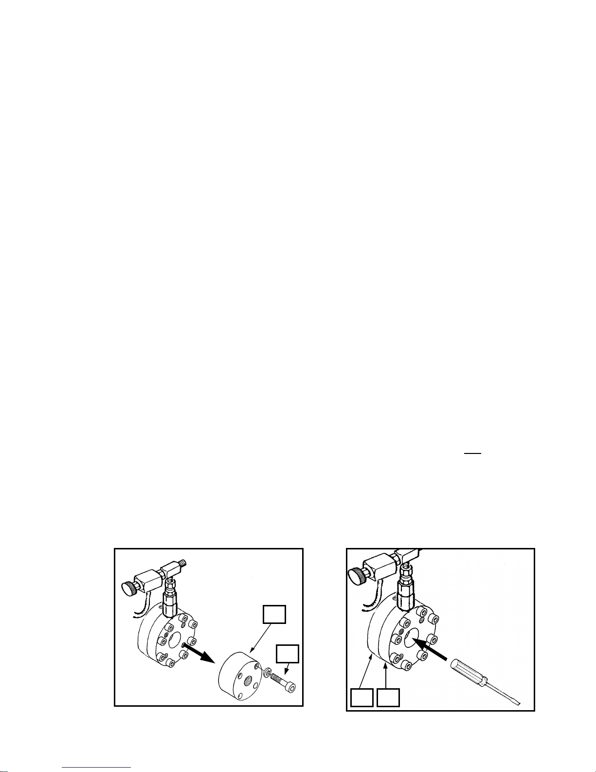
To eliminate the hydraulic side of the pump (piston / oil side of hydrapulse membrane) as a source of
problems;
1. Remove the intake valve end cap (ref# 16) by removing the four cap screws (ref# 14). The intake valve
assembly, (ref# 16-24), will generally come off as an entire assembly, requiring no further dismantling.
If the ball guide (ref# 23) and ball stop (ref# 24), remain in the paint head, they can be pried free with a
screwdriver.
2. Start unit.
3. Increase the pressure by turning the pressure control knob (ref# 71) clockwise to full pressure.
4. Put pressure on the center of the exposed hydrapulse membrane with the handle of a screwdriver or
other blunt object.
NOTE: The hydrapulse membrane is located between the paint head (ref# 27) and the hydraulic head
(ref# 51)
5. If you are:
-UNABLE to stop or alter the hydrapulse membrane's movement, then the hydraulic side is operating
properly. The problem is located in the “Paint” pump. See troubleshooting guide for additional
information.
-ABLE to stop or alter the hydrapulse membrane's movement, then the hydraulic pump is not operating
properly. The problem is located in the “Hydraulic” pump. See troubleshooting guide for additional
information.
H.E.R.O. INDUSTRIES LTD. 1100MD OWNERS MANUAL - “B” VERSION
16
14
51 27
15
Page 17
TROUBLESHOOTING
SITUATION
POSSIBLE CAUSE (REMEDY)
ELECTRIC MOTOR WON'T START/RUN
1. Unit unplugged or building circuit fuse is blown. (check, replace or reset fuse)
2. Pump under pressure. (reduce pressure setting by turning pressure control knob counter-clockwise,
trigger gun to relieve pressure).
3. Too light or too long of extension cord. (replace with correct cord. If distance greater than 100 feet,
obtain and install extra length of H.E.R.O. airless spray hose).
4. Unit's thermal overload switch has opened. (determine and correct ca use of overheating).
ELECTRIC MOTOR STALLS/QUITS
1. See "Electric Motor Won't Start/Run
2. Drive belt is loose. (tighten drive belts by evenly turning belt tension bolts on either side of motor
clockwise. Loose belts generally emit loud squealing noises).
3. Unit builds pressure, but pump “seizes” or “stops” when gun is triggered. ( loose belts, tighten).
NO PRESSURE, BLUE HYDRAULIC FLUID IN PAINT
1. Hydrapulse membrane broken. (replace hydrapulse membrane,(ref# 46). Closely follow detailed
instructions on page 20. NOTE; If, and only if, paint has contaminated the hydraulic side of the pump,
the entire hydraulic system must be cleaned and flushed. Make sure to remove and clean the hydraulic
tank screen,(ref# 63), during this process. Refill only with genuine H.E.R.O. LVO hydraulic fluid.
NOTE; If lacquer has contaminated the hydraulic system, the piston seal, (ref# 87), must be changed in
addition to flushing the system. Closely follow detailed instructions on page 23-24).
HYDRAULIC SIDE OF PUMP HAS BEEN REPAIRED AND REASSEMBLED, HYDRAPULSE
MEMBRANE NOT MOVING "PURGING"
1. Air lock created on hydraulic side of pump. (when the hydraulic side of the pump is working there is no
air in it. During repairs it is possible that air has been trapped in the hydraulic system. It must be
removed or the pump will not work. To purge the air from the hydraulic system; remove the pressure
control knob,(ref# 71), from the valve. Gently pull the P.C. stem,(ref# 74), out. It will pull out about
1/8". Remove the vented hydraulic cap,(ref# 65), from the hydraulic tank,(ref# 62), and install accessory
pressure cap, item 4-45-3. With a bicycle pump, apply a few pounds of air pressure to the hydraulic tank.
This will force the oil through the hydraulic system and push out any of the trapped air. Wait a few
minutes. Remove pressure cap and replace with vented cap. Restart the unit and install pressure control
knob. NOTE: Unit may be running during purging procedure to speed up the procedure. If a pressure cap
is unavailable, simply running the equipment for approximately 5-10 minutes with the P.C. stem pulled out,
will purge the system).
Accessory
Item
4-45-3
H.E.R.O. INDUSTRIES LTD. 1100MD OWNERS MANUAL - “B” VERSION
16
Page 18

TROUBLESHOOTING
SITUATION
POSSIBLE CAUSE (REMEDY)
TOTAL LOSS OF PRESSURE, HYDRAPULSE MEMBRANE MOVEMENT CANNOT BE STOPPED
OR ALTERED. (SEE "HYDRAPULSE MEMBRANE TEST")
1. Paint too thick. (thin paint according to manufacturer's recommendations).
2. Intake ball (ref# 20) worn or jammed opened/closed. (remove intake endcap (ref# 16) and ball guide
(ref# 23). Inspect intake ball,(ref# 20), to ensure it is free, round, and has no nicks or cuts. Inspect ball
guide for excessive "bashing out" on the internal walls. Excessive wear causes the ball to become "lost"
and unable to locate the seating surface. Inspect for foreign material jamming ball. Replace parts as
needed).
3. Intake seat loose/bypassing. (remove intake endcap,(ref# 16) and ball guide, (ref# 23). remove seat (ref#
18) and inspect washer (ref# 17) for excessive compression. Inspect for any sign of material bypass
between intake seat and endcap cavity. NOTE; The proper alignment of intake parts, condition of intake
washer, o-rings, combined with the correct bolt torque are critical to the correct function of the intake
valve. Replace the intake washer (ref# 17), each time the endcap is removed.
4. Outgo valve ball (ref# 36) worn or jammed. (remove outgo valve,(ref# 32). Invert valve and unthread
outgo valve upper,(ref# 39), from outgo lower,(ref# 33). Remove crush washer,(ref# 34), outgo seat,
(ref# 35), outgo ball,(ref# 36), outgo cage,(ref# 37), outgo spring,(ref# 38), from outgo upper tunnel.
Inspect outgo ball to ensure that it is round and free of nicks or cuts. Inspect for foreign material
jamming ball. Inspect ball and cage for wear. Replace parts as needed).
5. Outgo valve (ref# 32) incorrectly assembled. (disassemble and reassemble outgo valve, closely
following detailed instructions on page 22).
TOTAL LOSS OF PRESSURE, HYDRAPULSE MEMBRANE HAS NO MOVEMENT OR
MOVEMENT CAN BE STOPPED. (SEE "HYDRAPULSE MEMBRANE TEST")
1. Hydraulic intake valve (ref# 59) defective. (remove hydraulic feed line,(ref# 60), from hydraulic
intake valve. Plug hydraulic feed line so hydraulic fluid does not drain. Remove hydraulic intake valve
from elbow,(ref# 147). Check hydraulic intake valve to ensure that it flows in one way only, into the
cylinder. Replace if necessary. NOTE; Item cannot be repaired ).
2. Air lock created on hydraulic side of pump. (air entering hydraulic side due to loose hydraulic feed
line fittings, (ref# 60), punctured hydraulic feed line, poor seal at hydraulic intake valve, (ref# 59), or
elbow, (ref# 147). Tighten hydraulic feed line, test for leaks, or apply Teflon tape or pipe sealant on
fittings. Purge air as per detailed instructions below).
3. Pressure control valve ball (ref# 84) worn out/jammed. (remove hydraulic return line, (ref# 69), from
pressure control valve fitting,(ref# 78). Remove pressure control valve,(ref# 70), from elbow, (ref# 59).
Disassemble pressure control valve, by removing valve seat,(ref# 83), from body, (ref# 79). Inspect for
and remove foreign material. Inspect ball for wear. Install pressure control repair kit,(ref# 85), if
necessary).
4. Piston rod (ref# 90) disconnected from piston (ref# 88). (reconnect piston rod following detailed
instructions on page 23-24).
SPRAYER DOES NOT PRIME WITH PAINT
1. Heavy bodied paint, air lock. (refer to " Setting Up To Spray" and follow instructions.
H.E.R.O. INDUSTRIES LTD. 1100MD OWNERS MANUAL - “B” VERSION
17
Page 19

TROUBLESHOOTING
SITUATION
POSSIBLE CAUSE (REMEDY)
PUDDLE OF OIL APPEARING UNDER SPRAYER DURING OPERATION
1. Hydraulic fitting loose/cracked or hydraulic lines are punctured. (examine all hydraulic lines and fittings
for cracks, breaks or looseness. Replace or tighten as required).
2. Piston seals (ref# 87) worn. (remove and replace piston seals, following closely the detailed
instructions on page 23-34).
CORRECT STATIC PRESSURE, BUT REDUCED SPRAYING PRESSURE
(Check with pressure gauge, see page 15 for details).
1. Spray tip worn out/too large. (replace with new, correct sized spray tip. Tip most not exceed a newer
condition .031 tip ).
2. Paint hose incorrect. (replace hose with genuine H.E.R.O. airless spray hose (min. 50 feet). Steel
braided hoses must not be used ).
3. Intake valve seat (ref# 18) worn. (replace intake seat closely following detailed instructions on page 21).
4. Intake ball (ref# 20) worn. (replace intake balls when signs of wear, deformation, nicks or cuts are
evident. An out of round ball is the sign of a worn intake seat,(ref# 18), and both items should be
replaced).
5. Outgo seat (ref# 35) worn. (replace seat).
6. Outgo ball (ref# 36) worn/damaged. (replace outgo ball).
LOW STATIC PRESSURE, LOW SPRAY PRESS URE
(Check with pressure gauge, see page 15 for details).
1. Pressure control valve stem screw (ref# 76) loose. (remove pressure control knob,(ref# 71), and inspect
screw for looseness. Screw should be secured to stem, (ref# 75), with Loc-Tite. If the screw turns
independent of the stem than it must be re-secured. Secure unit so it will not move. Install pressure gauge
and .021 spray tip. Obtain a piece of wood, to use as a pusher or purchase a pressure control adjustment tool,
27C-15. Remove pressure control screw and put some Loc-Tite 609 on threads. Turn the screw into the
stem a few turns and push it in to its maximum and read pressure. Turn the screw in or out until 3000 psi
static pressure is obtained. If you obtain a pressure which higher than 3000 psi, trigger gun to release some
pressure and continue adjusting screw until correct pressure is obtained. Let Loc-Tite set up.
2. Pressure control ball (ref# 84) and/or seat (ref# 83) worn. (remove entire pressure control valve,
(ref# 70), from sprayer. Remove valve seat, ball, retainer,(ref# 82), and spring,(ref# 81), from valve.
Replace with pressure control repair kit,(ref# 85). Hold valve body vertical while placing in spring,
followed by retainer. Retainer should be below the valve body (approx. 3/8") when positioned correctly.
Center ball on retainer, turn valve seat into body until finger tight, using pipe dope or Teflon tape to
seal. Fully tighten using wrench.
SPRAY PATTERN LEAVES LINES OR FINGERS
1. Pressure too low. (increase pressure slowly until problem is corrected).
2. Worn tip. (replace tip).
3. Tip too small for spray material. (change to larger tip or increase pressure. See material manufacturers
H.E.R.O. INDUSTRIES LTD. 1100MD OWNERS MANUAL - “B” VERSION
18
Page 20

recommendations).
TROUBLESHOOTING
SITUATION
POSSIBLE CAUSE (REMEDY)
FLUID BEING SPRAYED OUT OF TIP PULSATES, SPRAY HOSE LIES QUIET WHEN GUN
TRIGGER CLOSED
1. Spray tip worn out or too large. (replace with new tip of correct size. Tip must not exceed a good
condition .031 tip ).
2. Paint hose incorrect type. (replace with genuine top quality H.E.R.O. airless spray hose. Steel braided
hose is not recommended ).
3. Too short a length of hose. (minimum 50' of airless spray hose is required. Replace or add hose until a
minimum of 50' is being used).
FLUID BEING SPRAYED OUT OF TIP PULSATES, SPRAY HOSE CONTINUES TO MOVE
VIGOROUSLY WHEN GUN TRIGGER CLOSED
1. Outgo valve (ref# 32) assembled incorrectly. (remove the outgo valve and reassemble closely following
the instructions on page 22).
2. Outgo valve ball (ref# 36) worn out or jammed. (inspect outgo ball to ensure that it is round and free of
nicks or cuts. Inspect for foreign material jamming ball. Inspect seat and cage for wear. Replace parts as
required).
PUMP SPRAYS WATER OR SOLVENT AT CORRECT PRESSURES, BUT WILL NOT SPRAY
PAINT (Check with pressure gauge, see page 15)
1. Air leak in paint intake assembly. (check all fittings and hose clamps in intake assembly for
tightness).
2. Air leak in paint intake. (check for cracked or broken intake fittings. Swivel connector, (ref# 11), or
elbow,(ref# 13), may be damaged due to over tightening. Look for small black hairline fractures.
Replace damaged parts).
3. Partial blockage in paint intake hose, (ref# 7). (clean and remove any blockages from intake hose.
Check to insure strainer bag is not clogging intake hose).
SPRAY PATTERN IS SPOTTY OR UNEVEN
1. Pressure is too low. (increase pressure slowly until problem is corrected ).
2. Spray material too thick. (thin as recommended by material manufacturer).
3. Plugged: tank screen, intake tube, gun filter or a combination. (inspect and clean or replace as
required).
4. Plugged tip. (remove and clean tip).
5. Pump malfunctioning or unsuitable for the material. (refer to other areas of troubleshooting guide and
check material requirements vs 1100MD output abilities).
EXCESSIVE OVE RSPRAY OR FOGGING
1. Pressure too high. (reduce pressure as required).
2. Material too thin. (follow material manufacturers recommendations re-thinning).
3. Tip too large. (reduce tip size).
4. Improper application technique. (refer to proper application techniques on page 9-11).
5. Too windy. (wait for wind to let up).
H.E.R.O. INDUSTRIES LTD. 1100MD OWNERS MANUAL - “B” VERSION
19
Page 21
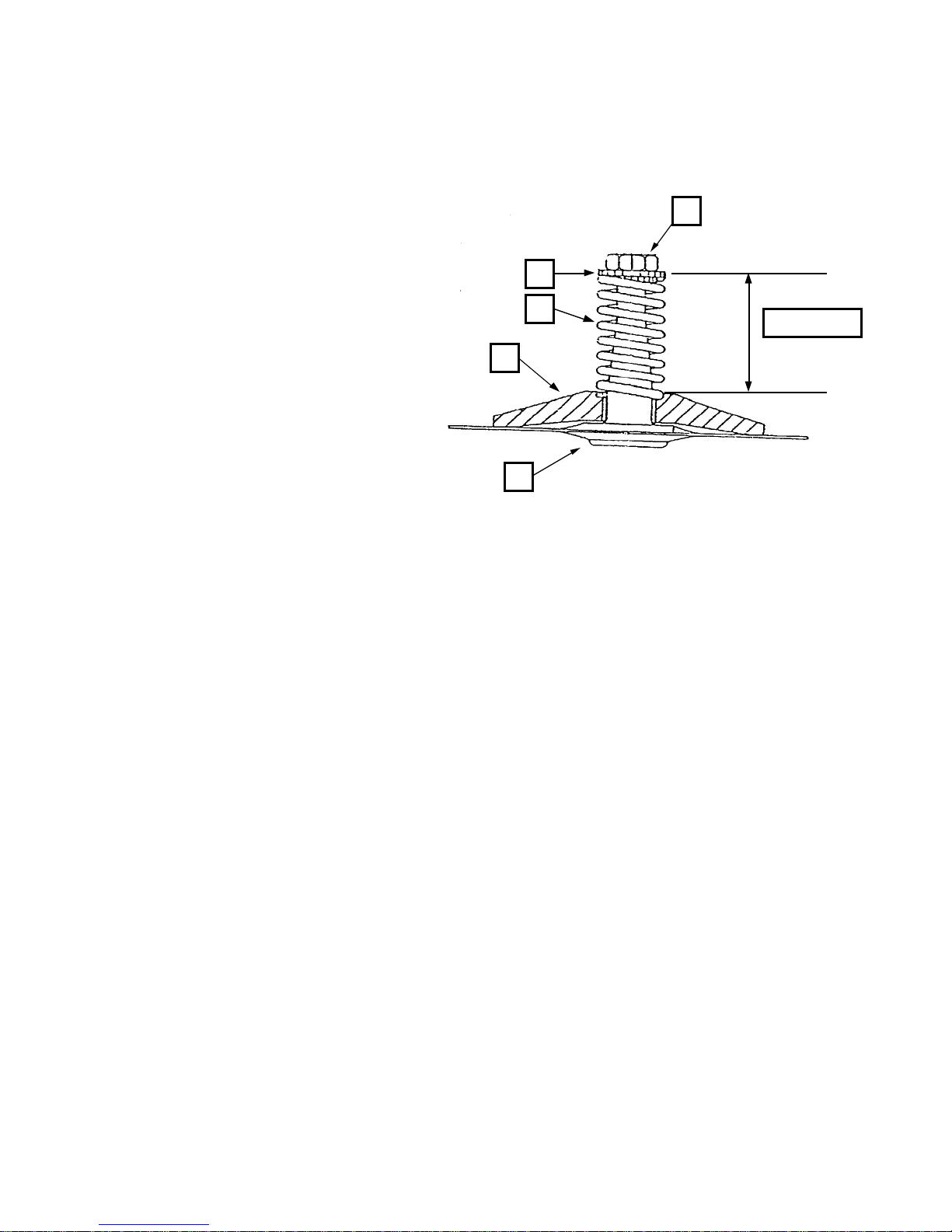
HYDRAPULSE MEMBRANE REPLACEMENT
( REF# 46 - KIT )
49
48
47
TOOLS REQUIRED
-1/4" Allen wrench
-1/2" Open end wrench (2)
-4-45-3 (accessory item)
-Torque wrench
46
Removal
1. Remove the eight bolts securing the material head (ref# 27) to the hydraulic head (ref# 51).
2. Remove the material head cushion (ref# 28) and replace with the new one supplied.
3. Place a container under pump to catch hydraulic oil.
4. Gently pull hydrapulse membrane to separate it from the hydraulic head.
5. Remove the nut (ref# 50) on the hydrapulse membrane stem in order to separate the hydrapulse
membrane from the hydraulic plastic horn (ref# 47), hydrapulse membrane spring (ref# 48), and spring
locator (ref# 49).
6. Clean all parts.
Assembly
1. Place hydraulic plastic horn over the new hydrapulse membrane.
2. Position the spring in the bore of the plastic horn.
3. Install the spring locator over the hydrapulse membrane stem and into the spring. Thread the jam nut
(ref# 50 - new one provided) onto the stem.
4. Tighten the jam nut until a measurement of 1-5/16” is obtained. The measurement is taken from the
top of the hydraulic horn (ref# 47) to the top of the spring locator ( ref# 49). See diagram above.
5. Check the assembly. The spring must be positioned in the bore of the plastic horn on one end and over
the shoulder of the spring locator on the other end. Any stem material protruding past the nut may be
ground off ( stem should be just past flush with nut )
6. Place the hydrapulse membrane assembly back into the hydraulic head.
7. Re-install the material head with the eight bolts. Torque to 30 ft. lbs.
8. Refill hydraulic oil tank and "PURGE" system following instructions on page 16.
9. Prime the pump with solvent or water and bring the pump up to full pressure (approximately 2500 psi.).
Run the pump on standby ( not triggering gun ) for about 20 minutes, to “break-in” new membrane.
10. Installation is now complete and the pump is ready for use.
50
1-5/16 Inches
H.E.R.O. INDUSTRIES LTD. 1100MD OWNERS MANUAL - “B” VERSION
20
Page 22
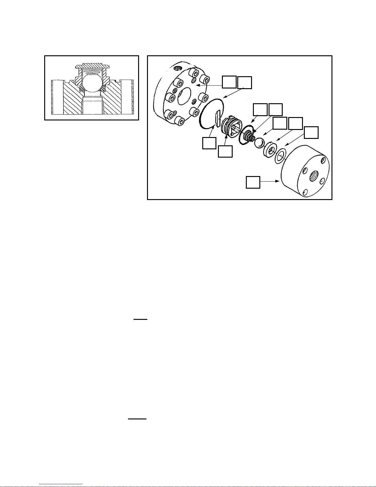
REPLACEMENT OF INTAKE SEAT
(REF # 18)
25
27
22 21
20
18
17
TOOLS REQUIRED
-5/16" Allen wrench
-vise
-torque wrench
-screwdriver
1. Remove the four bolts (ref# 14) and pull intake endcap (ref# 16), from the pump. The endcap should
separate from the material head (ref# 27), with the ball guide (ref# 23) attached. If the ball guide
remains in the material head, pry out with a screw driver.
2. Clam p endcap in vise with the ball guide facing up.
3. Pry off the ball guide and remove intake ball (ref# 20) and spring (ref# 21).
4. Remove seat from endcap. NOTE; The seat is not secured with any Loc-Tite, however dried paint
may cause difficulty in remov ing seat.
5. Remove the crush washer (ref# 17).
6. Thoroughly clean and inspect all parts. Replace any worn or damaged parts.
7. Place clean endcap in vise with o-ring (ref# 25) groove facing up.
8. Assembly of parts is the reverse of removal; washer (ref# 17), seat (ref# 18), and ball (ref# 20).
NOTE; A new compression washer should be used each time the endcap is removed
9. If the ball guide (ref# 23) and ball stop (ref# 24) were separated during removal, re-assemble the two.
NOTE; The step on the ball stop must face outwards ( Towards hydrapulse membrane ).
10. Place the spring (ref# 21) into the ball guide so the smaller end of the spring will contact the ball.
11. Assemble the ball guide, with spring, onto the endcap over the already installed ball and seat. Push
down on the ball guide so that the ball guide o-ring (ref# 22) locks the assembly together.
12. Place o-ring (ref# 25) in the groove on the face of the endcap.
13. Install the entire endcap assembly onto the material head with the four bolts (ref# 14). Torque bolts,
using a crisscross pattern, to 20 ft. lbs. Repeat torquing procedure using 30 ft. lbs.
NOTE: Effective March 1997, and beginning with serial number 190031, a new style Hydrapulse
“Intake” assembly is used. The changes effect the Endcap (ref# 16), Crush Washer (ref # 17), Ball Guide
(ref# 23), Ball Stop (ref# 24), and the Material Head (ref# 27). The most significant change is to the
endcap. Gone is the o-ring, formerly located under the intake seat. The endcap is machined flush and a
new crush washer is now placed in bef ore the seat ( crush washer is placed under the seat ). The seat will
be held in place through the compression of parts during assembly.
24
23
16
H.E.R.O. INDUSTRIES LTD. 1100MD OWNERS MANUAL - “B” VERSION
21
Page 23
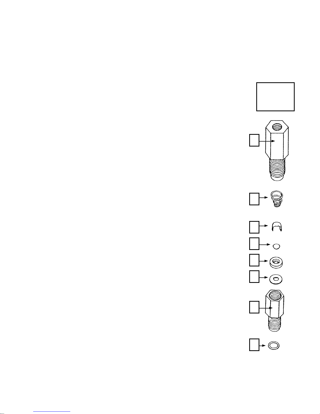
OUTGO VALVE
(REF# 34)
TOOLS REQUIRED
-1" wrench
-vise
-Teflon tape
1. Remove pressure control knob, (ref# 71) and pull P.C. stem, (ref# 74) out to
internal stop, thereby releasing hydraulic pressure.
2. Trigg er gun to release pressure from the material side of pump.
3. Disconnect outgo tee assembly, (ref# 43) from outgo swivel, (ref# 40) on
the outgo valve.
4. Remove outgo valve from machine by turning counter clockwise.
5. Invert valve and secure upper part of valve, (ref# 39) in vise.
6. Remove lower half of valve, (ref# 33).
7. Remove crush washer, (ref# 34), seat, (ref# 35), ball, (ref# 36), cage, (ref#
37) and spring, (ref# 38). Clean and inspect all parts for wear. Replace any
worn parts.
8. Apply Teflon tape to threads of outgo upper body.
9. Place spring, large end first, into outgo body. Spring should fit into slot
machined into tunnel.
10. Place cage onto spring, with open end up.
NOTE: Cage should be open so that it drags down the sides of the tunnel
during installation. If closed too much it will trap the ball and cause
pulsation in spray pattern.
11. Place ball into cage.
12. Install seat, beveled side down to ball. Seat should fit snugly into outgo
body. Press on seat to ensure it will compress until it is flush with outgo
body. Release slowly to ensure the parts do not dislodge themselves.
13. Place crush washer on seat. Replace crush washer if badly crushed.
14. Thread outgo lower onto outgo upper until finger tight. Tighten 1/2 turn with
wrench. NOTE: Teflon tape or pipe sealant should be used.
15. Attach repaired valve to machine, installing a new crush washer, (ref# 31)
following steps 3-4 in reverse order.
SPECIAL NOTES:
* To check the ball for wear, place against a new seat and check sealing edge
against a bright light.
* A used seat may be checked in a similar manner using a new ball. Replace
used part if light pass at sealing edge.
Outgo
swivel
ref# 40
3
3
3
3
3
3
3
3
H.E.R.O. INDUSTRIES LTD. 1100MD OWNERS MANUAL - “B” VERSION
22
Page 24
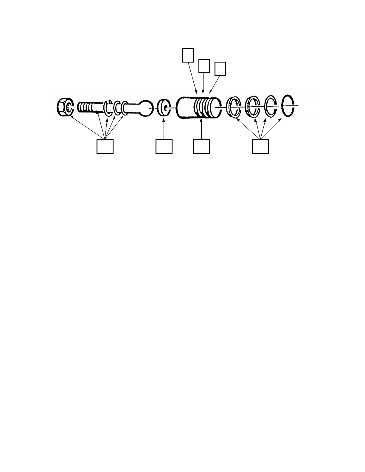
PISTON REPAIRS
(REF# 86)
TOOLS REQUIRED
-1/2" wrench
-11/16" wrench
-circlip pliers
-torque wrench
-grease
-vise grips
1. Remove hydraulic feed line, (ref# 60) from hydraulic intake valve, (ref# 59) and also remove hydraulic
return line, (ref# 69) from the pressure control valve, (ref# 70). Plug lines to minimize oil loss. (Hint;
golf tees work well for this)
2. Remove the bolts, (ref# 57) passing through the side frames, (ref# 106, 107), into the crossblock,
(ref# 56).
3. Place a drain tray under cylinder area.
4. Grasp the pump assembly, and pull away from the piston. Stop when piston pulls free, to allow the
hydraulic oil to drain into pan. Completely remove pump assembly from between side frames.
5. If only replacing piston seals, (ref# 87) continue at step 15.
6. Remove the piston, (ref# 86) from eccentric bearing, (ref# 95). Move to clean work bench for repairs.
7. Remove piston circlip, using circlip pliers. Remove piston from rod.
NOTE: Use extreme caution not to damage circlip or the internal circlip groove of piston.
NOTE: Piston rod circlip, washer, o-ring, and nut are not available individually. Parts are available
with the purchase of piston rod, (ref# 90) only.
NOTE: The circlip will have one sharp edge and one smooth edge. The smooth edge should be towards
the washer. If reversed, the rod will continually pull out of the piston.
8. Remove bronze piston rod seat, (ref# 89) from piston, (ref# 88).
9. Examine all parts for wear or damage. Replace as required.
10. Fill the center cavity of piston rod seat until flush with grease. Slide seat into piston with concave side
(filled with grease) facing out.
11. Lightly grease the ball end of piston rod. Push piston rod into piston until ball end of rod contacts seat.
90 89 88 87
A
B
C
PISTON REPAIRS
H.E.R.O. INDUSTRIES LTD. 1100MD OWNERS MANUAL - “B” VERSION
23
Page 25

12. Slide o-ring and steel washer down rod and into piston. Slide circlip down into piston and snap into the
internal circlip groove of piston using circlip pliers.
NOTE: Circlip must fully expand into groove of piston. Circlip has fully expanded when there is
13/64" space between circlip eyelets.
NOTE: If you experience difficulty installing circlip, remove a small quantity of grease. When
installed correctly, rod should move slowly and without any free play.
13. If piston seals, (ref# 87) are required, they may be installed now or after piston has been re-attached.
14. Thread rod into eccentric bearing holder, (ref# 95) until nut is flush with eccentric bearing. Tighten
snugly.
NOTE: Piston rod nut must remain fully threaded onto rod, if during installation, the nut begins to
loosen from rod, re-tighten to rod. Place vise grips on rod to assist in tightening piston rod into
eccentric.
15. Remove and discard old piston seals.
16. Piston seal kits, (ref# 87) contain a total of four pieces (1 o-ring, 1 flat washer, 2 cup washers). Take
note of their installation sequence by referring to drawing. The piston has three machined grooves,
which have been marked on the drawing as A, B, & C.
17. Place flat washer (one side has a contoured face) into groove "C", then place o-ring in front of flat
washer, so that it fits into the contoured face of the flat washer.
18. Place one cup washer into groove "B", with open face of cup washer facing the end of piston. (towards
hydraulic oil when installed)
19. Place second cup washer into groove "A".
NOTE: Always work from the front of the piston back so that you are always moving the cup
washers over filled grooves. This avoids damage that can occur to the cup washers if they have to be
dug out of one groove and moved to another. Avoid over stretching.
NOTE: A small, dental like tool, may be used to assist in moving cup washers.
20. Apply grease to seals before installing in cylinder, (ref# 53).
21. Slide pump assembly into side frames and guide piston into cylinder.
NOTE: Use care not to push the piston too far into cylinder. If piston rings slide in too far they will pass
through cylinder into the hydraulic cavity. Complete dismantling of piston will be required to remove.
The piston can not be pulled back if the seals have gone through cylinder.
22. Reattach crossblock bolts, as removed in step 2. Torque bolts to 30 foot pounds.
23. Reconnect hydraulic lines, as removed in step 1.
24. Add new hydraulic oil to hydraulic tank, using only genuine H.E.R.O. LVO hydraulic oil.
25. Once the repairs have been completed, the hydraulic oil will require purging to remove the trapped air.
See "PURGING" instructions on page 16.
H.E.R.O. INDUSTRIES LTD. 1100MD OWNERS MANUAL - “B” VERSION
24
Page 26
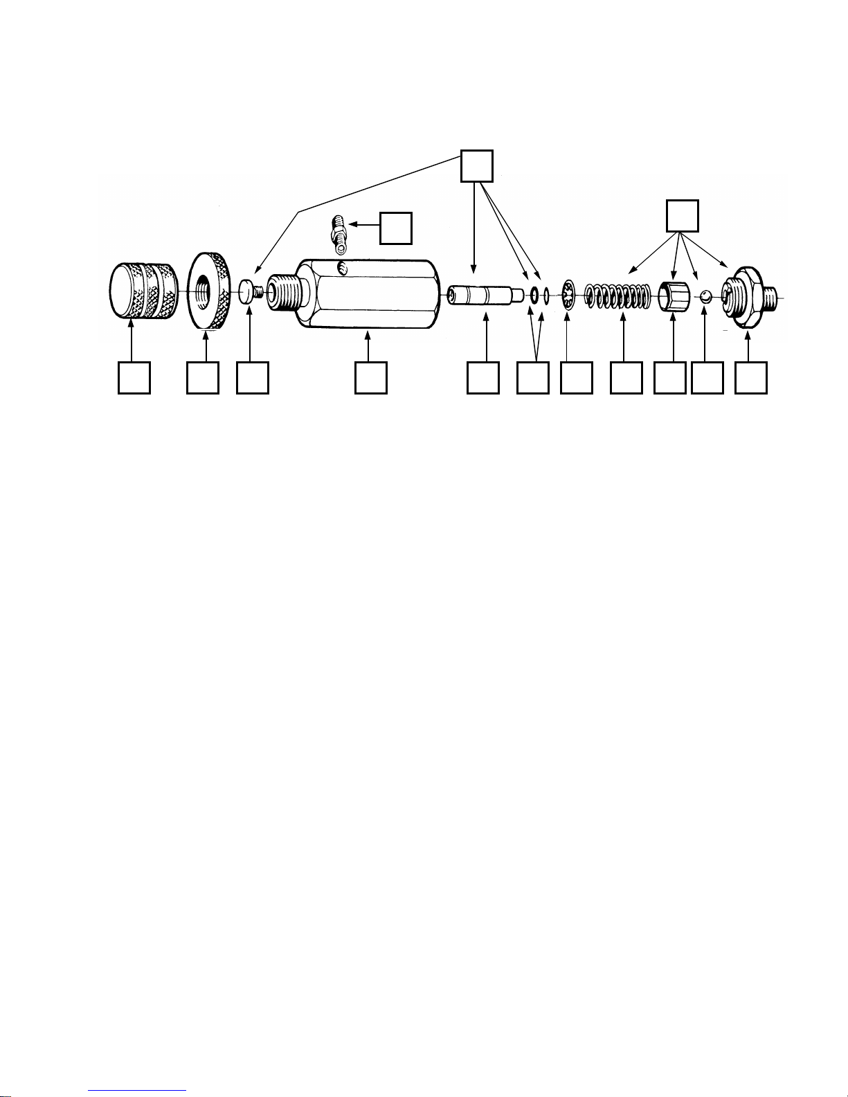
PRESSURE CONTROL VALVE
(REF# 70)
TOOLS REQUIRED
-1" wrench
-11/16" wrench
1. Remove pressure control knob, (ref# 71) and pull P.C. stem, (ref# 74) out to the internal stop (1/16" to
1/8") thereby releasing hydraulic pressure.
2. Remove hydraulic return line, (ref# 69) from P.C. fitting, (ref# 78).
3. Place 11/16" wrench on P.C. seat, (ref# 83). Turn counter-clockwise to remove complete valve.
4. Place complete valve in vise and remove seat from body, (ref# 79).
5. Remove ball, (ref# 84), retainer, (ref# 82), and spring, (ref# 80) from body. Inspect ball for nicks or cuts
and replace if damaged. Inspect seat at sealing edge, for signs of wear. A good condition seat will have
a very small beveled at the sealing edge. The larger the bevel the more wear has taken place. Inspect
retainer for wear. The retainer has a small locating hole in it. The hole should be flush or slightly
beveled. The greater the wear on the ball, seat, and retainer the poorer the static pressure will be.
Replace parts individually, or use repair kit, (ref# 85).
6. Hold P.C. body vertical. Place spring into body, place retainer onto spring. Ensure retainer fits
completely over spring. Retainer should rest below end of body by approximately 1/4" to 3/8". Place
ball onto retainer, ensuring ball is located on center hole.
7. Thread on seat, using care not to dislodge the ball from its position on the retainer. Tighten firmly.
8. Apply pipe dope or Teflon tape to exterior threads of seat. Install into elbow. Tighten to prevent leaks
and return to original position.
9. Reattach hydraulic line.
10. See "PURGING" instructions on page 16.
71
78
79 76 73 84 82 81 80 83
74
85
77 75
H.E.R.O. INDUSTRIES LTD. 1100MD OWNERS MANUAL - “B” VERSION
25
Page 27

ACCESSORIES PARTS LIST
1/4x1/4 CONNECTOR, 1/4 PAINT HOSE TO 1/4 PAINT HOSE
106 RUBBER BAN
114 HOSE, AIRLESS PAINT 50' X 1/4"
115 HOSE, AIRLESS PAINT 25' X 1/4"
117 HOSE, AIRLESS PAINT 50' X 3/8"
3-WHIPEND WHIPEND, 3' X 3/8"
620-VHS SERVICE VIDEO TAPE, VHS FORMAT
621-BETA SERVICE VIDEO TAPE, BETA FORMAT
620-H2O HOW TO OPERATE VIDEO TAPE , VHS FORMAT
67/18B HEX KEY SET, 5/16",1/4",5/32",1/8"
10-55-011-2 AIRLESS SPRAY GUN, ASM, 2 FINGER TRIGGER
10-55-011-4 AIRLESS SPRAY GUN, ASM, 4 FINGER TRIGGER
5GAL SB STRAINER BAG, 5 GALLON
5GAL PL PLASTIC LINER, 5 GALLON
10-55-____ ZIP TIP INSERT, AVAILABLE IN THE FOLLOWING SIZES;
0904 1104 1304 1504 1704 1904 2110 2510 3112
0906 1106 1306 1506 1706 1906 2116 2712
1108 1308 1508 1708 1908 2104 2118 2910
1110 1310 1510 1710 1910 2106 2310 3104
1312 1512 1712 1912 2108 2312 3110
OTHER FAN SIZES ALSO AVAILABLE, BUT NOT ALWAYS STOCKED
4-649 WONDER WASH ( 48 PCS X 1.5 OZ. PKG )
4-650 WONDER WASH 5 OZ. PKG.
4-655 WONDER WASH ( 25 PCS X 5 OZ. PKG )
4-660 WONDER WASH BULK, 5 LBS.
4-662 WONDER COAT, 1 LITRE
4-664 WONDER COAT ( 12 PCS X 1 LITRE )
661 SPRAY TRIGGER, FOR USE WITH 4 -662
4-666 WONDER COAT, 4 LITRE
4-668 WONDER COAT ( 4 PCS X 4 LITRE )
4-6658B INTAKE REPAIR KIT NEW, after serial # 190031
4-6659B INTAKE OVERHAUL KIT ( Repair Kit + Seat ) NEW, after serial # 190031
4-6654 OUTGO REPAIR KIT
4-6655 OUTGO OVERHAUL KIT ( Repair Kit + Seat )
4-LVO-1 HYDRAULIC OIL, 1 LITRE
4-LV0-4 HYDRAULIC OIL, 4 LITRE
4-67/19 PRESSURE GAUGE C/W FITTINGS
4-45-3 PRESSURE CAP, HYDRAULIC TANK
10-QRP-3 QUICK REACH POLE, 3 FOOT GUN EXTENSION
10-QRP-5 QUICK REACH POLE, 5 FOOT GUN EXTENSION
10-QRP-8 QUICK REACH POLE, 8 FOOT GUN EXTENSION
PARTS LIST
H.E.R.O. INDUSTRIES LTD. 1100MD OWNERS MANUAL - “B” VERSION
26
Page 28
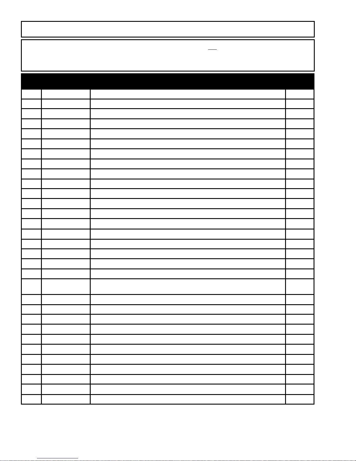
PARTS LIST
Please order parts by the appropriate part number and not by reference number.
The quantity required, per unit, is shown for ea ch part number. Part numbers in bold text indicate
whole assemblies or kits. These parts may also be purchased individually
INTAKE PARTS
REF PART # DESCRIPTION QTY
1 4-1/100-10A LID, Paint Tank, C/W Knob, 10 3/4" I.D., Ref# 1-3 1
2 4-1/75-6 KNOB, c/w Screw 1
3 HW3018P SCREW, 8-32 x 3/8, RD HD, Slot 1
4 1/100-9 TANK, 5 Gallon Paint 1
5 1/100-12 SCREEN, Paint Tank 1
6 4-1/75-14 TUBE ASSEMBLY, Intake Hose, Ref# 7-12 ASSY
7 4-1/75-2A HOSE, Lacquer Resistant, 12” 1
8 633C QUICK CONNECT, Upper 1
9 2/77 GASKET, Lacquer Resistant 1
10 633E QUICK CONNECT, Lower 1
11 1/75-1 SWIVEL, Connector 1
12 1/75-3 CLAMP 4
13 2/75 ELBOW, 90° 1
14 HW1087 CAPSCREW, SKT HD, 3/8 NC x 2", Gr. 8 4
15 3-2 WASHER, 3/8" Hi Collar Lock 4
16 4-02-22-2502B ENDCAP, Hydrapulse, Gold NEW, after serial # 190031 1
17 02-22-2009B WASHER, Crush NEW, after serial # 190031 1
18 6 SEAT, 3/4" Tungsten Carbide 1
19
20 17S BALL, 3/4", Corrosion Resistant 1
21 02-22-2005 SPRING 1
22 02-22-2006 O-RING, Urethane 1
23 02-22-2002 BALL GUIDE NEW, after serial # 190031 1
24 02-22-2001 BALL STOP NEW, after serial # 190031 1
25 5V O-RING, Viton 1
26 3 CAPSCREW, SKT HD, 5/16 x 1-3/4" 8
27 4-02-22-2501 HEAD, Material, Hydrapulse, Gold NEW, after serial # 1
28 02-22-2004 CUSHION, Material Head 1
NOT USED
29 4-6658B REPAIR KIT ( Ref# 17, 20-21, 25 ) NEW, after serial # 190031 KIT
30 4-6659B OVERHAUL KIT ( Ref# 17-25 ) NEW, after serial # 190031 KIT
H.E.R.O. INDUSTRIES LTD. 1100MD OWNERS MANUAL - “B” VERSION
27
Page 29
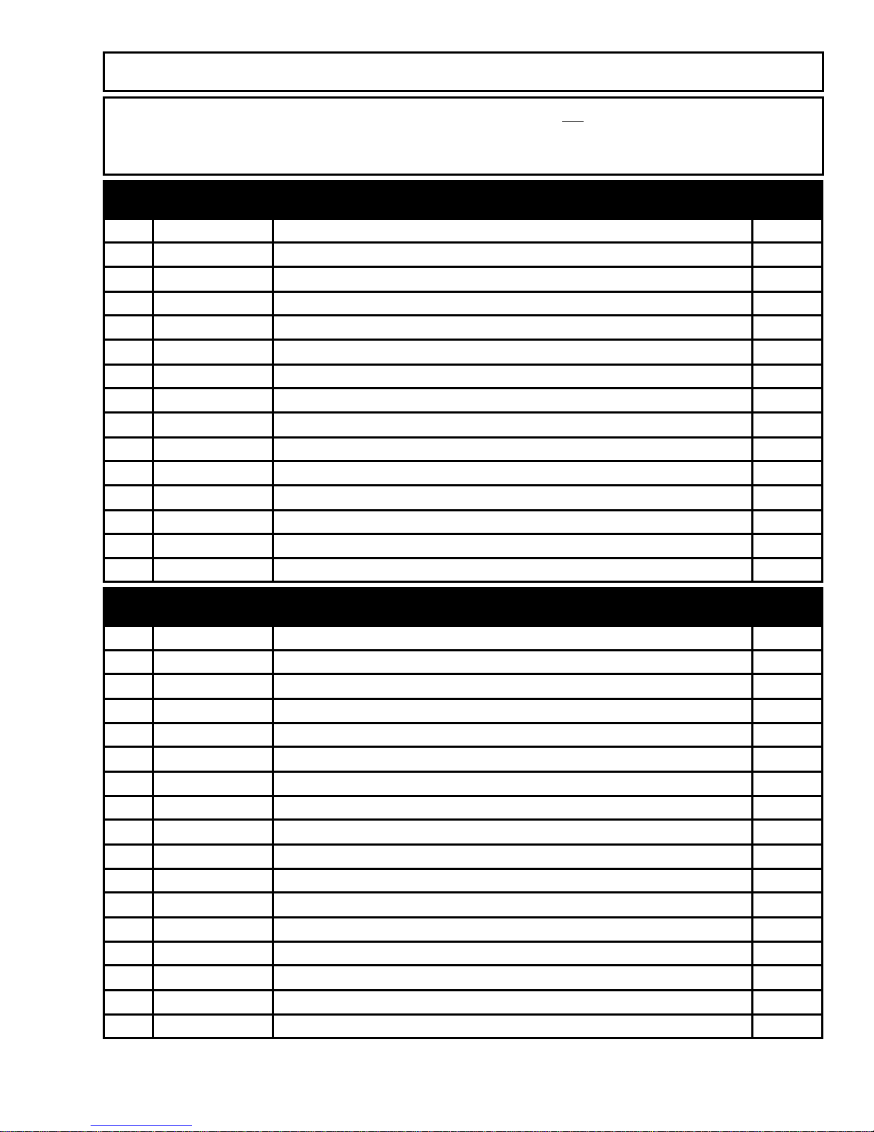
PARTS LIST
Please order parts by the appropriate part number and not by reference number.
The quantity required, per unit, is shown for ea ch part number. Part numbers in bold text indicate
whole assemblies or kits. These parts may also be purchased individually
OUTGO PARTS
31 7C WASHER, Copper Crush 1
32 4-11A OUTGO VALVE ASSEMBLY, ( Ref# 33-40 ) ASSY
33 11A-1 VALVE BODY, Lower 1
34 11A-3CP WASHER, Copper Crush 1
35 11A-4 SEAT, 3/8", Tungsten Carbide 1
36 11A-5 BALL, 3/8", Nylon 1
37 11A-6 CAGE 1
38 11A-7 SPRING 1
39 11A-2 VALVE BODY, Upper 1
40 20 SWIVEL 1
41 4-6654 REPAIR KIT ( Ref# 31, 34, 36-38 ) KIT
42 4-6655 OVERHAUL KIT ( Ref# 31, 34-38 ) KIT
43 4-13-1 TEE ASSEMBLY, ( Ref# 44-45 ) ASSY
44 13-1 TEE, Female x Male x Male 1
45 13A Plug 1
HYDRAULIC PARTS
46 4-04-22-4500 HYDRAPULSE MEMBRANE ( Includes Ref# 28, 50 ) KIT
47 04-22-4001 HORN, Plastic 1
48 04-22-4005 SPRING 1
49 04-22-4004 LOCATOR 1
50 HW4032 NUT, 5/15NC Hex Ny-Lock 1
51 4-04-22-4501 HEAD, Hydrapulse, Gold 1
52 5 O-RING 1
53 24/100 CYLINDER, 7/8" 1
54 HW5050P WASHER, 5/16" SAE, Plated 6
55 36 CAPSCREW, SKT. HD., 5/16NC x 2-3/4" 6
56 35A CROSSBLOCK, Aluminum 1
57 HW1060P CAPSCREW, HX. HD., 5/16NC x 3/4", Gr. 5 6
58 HW5050P WASHER, 5/16" SAE 6
147 25-2 ELBOW 3
59 4-30 VACUUM VALVE 1
60 4-31 FEED LINE ( Includes Ref# 61 ) Complete With Ferrules & Nuts ASSY
61 31-1 ORIFICE, Metering 1
H.E.R.O. INDUSTRIES LTD. 1100MD OWNERS MANUAL - “B” VERSION
28
Page 30
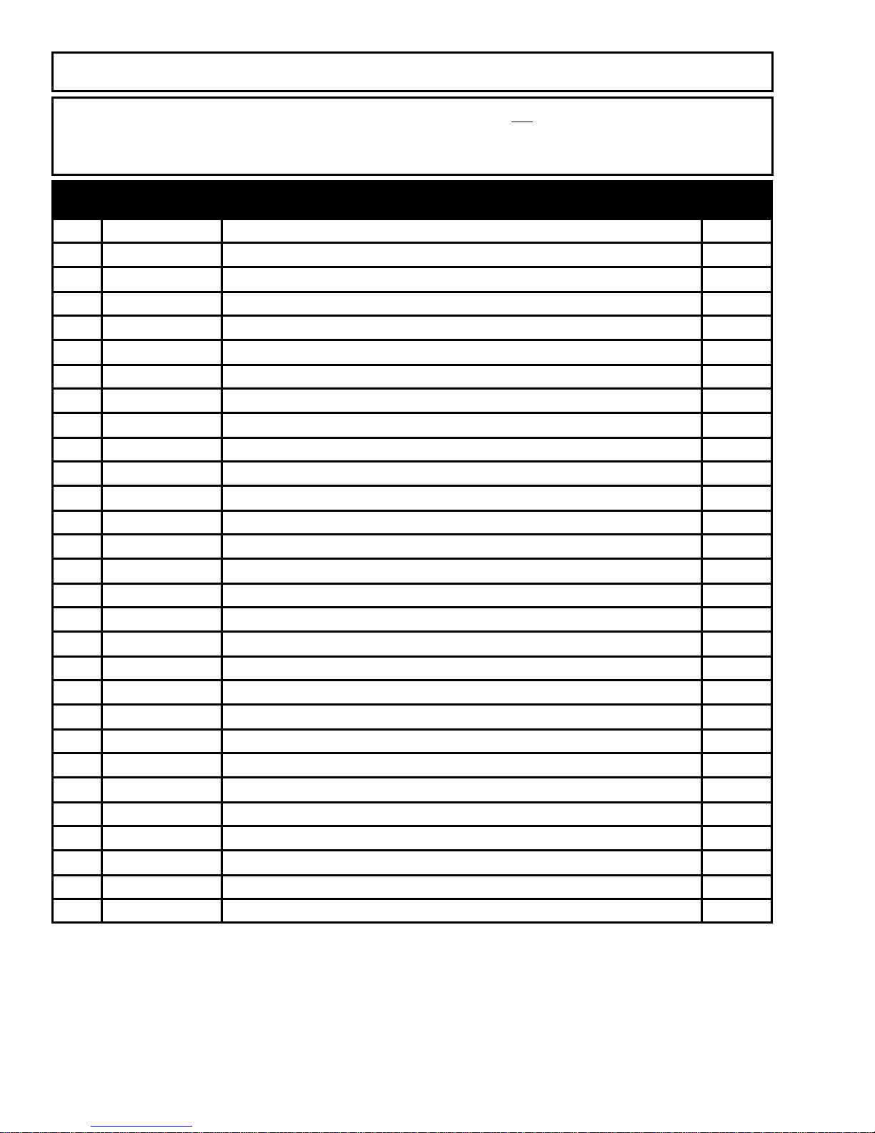
PARTS LIST
Please order parts by the appropriate part number and not by reference number.
The quantity required, per unit, is shown for ea ch part number. Part numbers in bold text indicate
whole assemblies or kits. These parts may also be purchased individually
HYDRAULIC PARTS
62 4-45A TANK, Complete. ( Includes Ref# 63-65 ) ASSY
63 4-45-1 SCREEN, Tank 1
64 45-4 ELBOW, Return 1
65 4-45-2 LID, Vented, Hydraulic Tank 1
66 45B BRACKET, Tank 1
67 HW1010P CAPSCREW, HX. HD., 1/4NC x 1/2" 2
68 45C STRAP 2
69 4-28 RETURN LINE, Complete With Ferrules & Nuts 1
70 4-27C PRESSURE CONTROL VALVE, Complete ( Ref# 71-84 ) ASSY
71 4-27C-7 KNOB, P.C., Includes Ref# 72 ASSY
72 HW2010 SETSCREW, SKT. HD. 5/16 NC x 5/16" 1
73 27C-6 LOCK NUT, Aluminum, P.C. 1
74 4-27C-10 STEM ASSEMBLY ( Ref# 75-77 ) ASSY
75 27C-10A STEM, P.C. 1
76 27C-10B SCREW, Stem, P.C. 1
77 27C-12 O-RING, P.C. 2
78 4-27C-11 FITTING, Oil Return, P.C. 1
79 27C-8 BODY, P.C. 1
80 27C-9 CIRCLIP, P.C. 1
81 27C-5 SPRING, P.C. 1
82 27C-4 RETAINER, P.C. 1
83 27C-3 SEAT, 38-40RC, P.C. 1
84 27C-2 BALL, Steel 1
85 4-27CRK REPAIR KIT, Ref# 81-84 KIT
86 4-38A/100 PISTON & ROD ASSEMBLY, 7/8" (Ref# 87-90 ) ASSY
87 4-37A/100 SEAL SET, Piston, 7/8" 1
88 4-38A/100-1 PISTON, Only, W/O Seals, 7/8" 1
89 38A-3 SEAT, Piston, Bronze 1
90 4-38A-2 ROD, Piston, C/W Nut, Washer, O-Ring, Circlip 1
H.E.R.O. INDUSTRIES LTD. 1100MD OWNERS MANUAL - “B” VERSION
29
Page 31
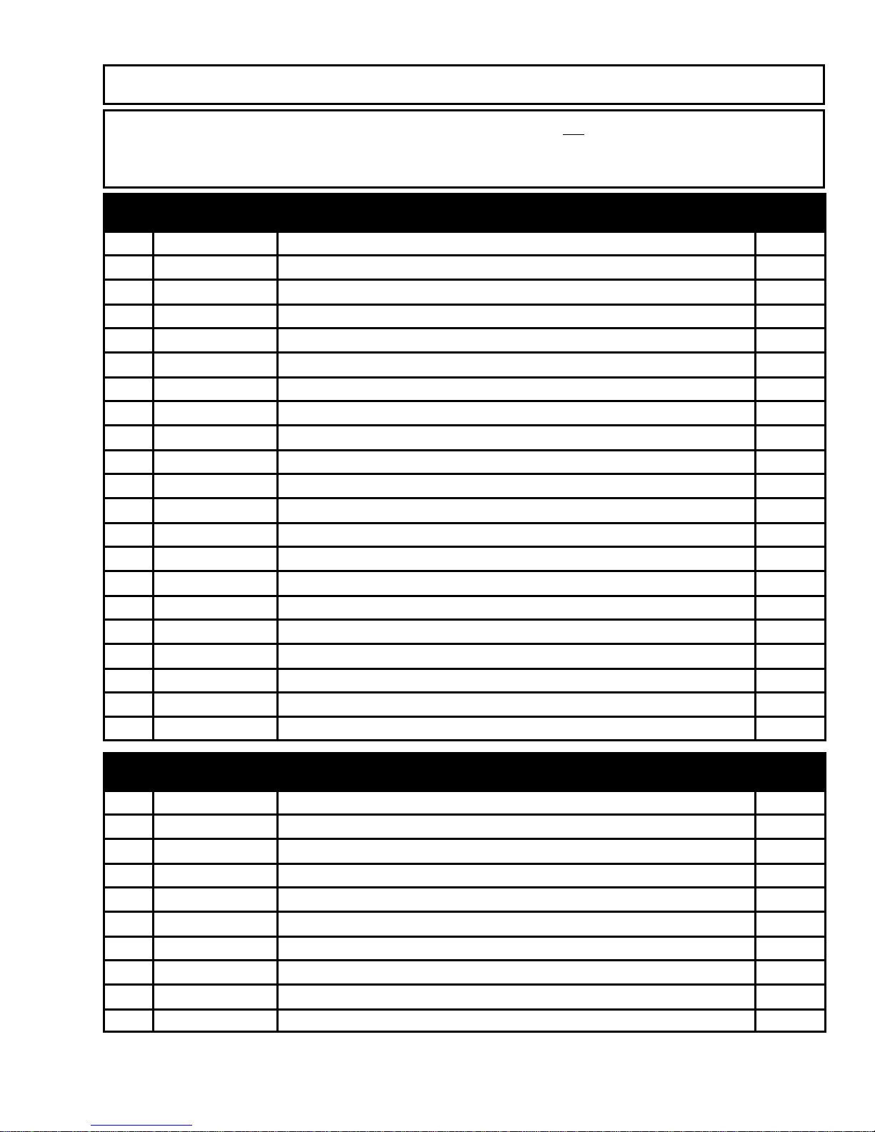
PARTS LIST
Please order parts by the appropriate part number and not by reference number.
The quantity required, per unit, is shown for ea ch part number. Part numbers in bold text indicate
whole assemblies or kits. These parts may also be purchased individually
DRIVE PARTS
91 05-80-5000 BEARING, Crankshaft Side 2
92 HW1055 LT. CARRIAGE, 5/16NC x 5/8" 4
93 HW5060P WASHER, Lock, 5/16 4
94 HW4030P NUT, HX. HD, 5/16 4
95 4-39 ECCENTRIC BEARING & HOLDER, C/W Zerk, (Ref# 96,97) ASSY
96 39-2 BEARING, Eccentric, Outer 1
97 4-39-3 Holder, Eccentric, C/W Zerk 1
98 4-41 CRANKSHAFT, Includes Ref# 99 ASSY
99 39-1 RACE, Eccentric, Inner 1
100 4-49 KEYSTOCK, 3/16 SQ x 1.5" 2
101 4-65/100 SHEAVE, Pump, C/W Set Screws (2) 1
102 HW2020 SET SCREW, SKT. HD., 5/16 NC x 7/16 2
103 66/100 BELT 1
104 4-48/100 SHEAVE, Motor, C/W Set Screws ( See Ref# 96 ) 1
105 4-61/100 MOTOR, 1.5 H.P., Marathon Motor, Includes Switch, Cord. 1
65/101M SWITCH, On/Off, Marathon Motors
61/105M FAN, Marathon Motors
61/106M CLIP, Fan, Marathon Motors
61/107M COVER, Fan, Marathon Motors
65/122-COV-M COVER, Capacitor, State Size, Marathon Motors
65/117 CORD, AC Power, Marathon Motors
CHASSIS PARTS
106 4-53 FRAME, Left Side 1
107 4-52 FRAME, Right Side 1
108 58 BRACKET, Motor Cord Wrap 2
109 HW1050P CAPSCREW, HX. HD., 5/16NC x 1/2" 1
110 4-51 ROD, C/W Clips ( Includes Ref# 110 ) 1
111 59 E-CLIP 2
112 4-50 BRACKET, Motor Mounting, Includes Ref# 112-113 1
113 HW1070F CAPSCREW, HX. HD., 5/16NC x 1-1/4", Gr. 5, Full Thread 2
114 HW4040 NUT, Hex Jam, 5/16" 2
115 4-06-140-453 LEG ASSEMBLY, Includes Ref# 115-116 1
H.E.R.O. INDUSTRIES LTD. 1100MD OWNERS MANUAL - “B” VERSION
30
Page 32
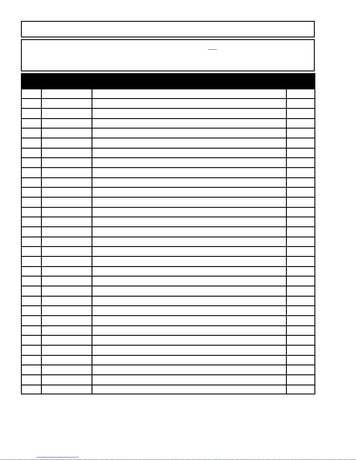
PARTS LIST
Please order parts by the appropriate part number and not by reference number.
The quantity required, per unit, is shown for ea ch part number. Part numbers in bold text indicate
whole assemblies or kits. These parts may also be purchased individually
CHASSIS PARTS
116 PW-4080 FOOT PAD, Includes Ref# 117 2
117 HW5090P WASHER, 1/2" SAE 2
118 4-67/39 BRACKET, Shroud Mounting 1
119 HW1022P CAPSCREW, HX. HD., 1/4NC x 1" 4
120 HW5030P WASHER, 1/4 SAE 4
121 HW5040P WASHER, 1/4 Lock 4
122 HW4020P NUT, Hex, 1/4NC 4
123 67/33 HANDLE, Lower, Left 1
124 67/34 HANDLE, Lower, Right 1
125 HW1020P CAPSCREW, HX. HD., 1/4NC x 3/4" 4
126 HW5030P WASHER, 1/4" SAE 4
127 HW5040P WASHER, 1/4" Regular Lock 4
128 HW4020P NUT, 1/4" Hex 4
129 67/36 AXLE, 5/16" Diameter 1
130 4-67/39 SPACER 2
131 67/16A WHEEL, 10" Pneumatic 2
132 67/17 COTTER PIN 2
133 633F CLIP, Spring 2
134 67/31 HANDLE, Upper 1
135 67/32 BAR, Cross, For Tank Mounting 1
136 HW30652P SCREW, Machine, 1/4-20 x 1-1/4, RD. HD., Slot 4
137 HW5040P WASHER, 1/4" Regular Lock 4
138 HW4020P NUT, 1/4" Hex 4
139 67/12 GRIP 2
140 4-1/100-13 CHAIN, 9" 1
141 66/100-1 BELTGUARD, Black 1
142 HW1020P CAPSCREW, HX. HD., 1/4 NC x 3/4" 2
143 66/11-2 SHROUD, Black, 1.5 HP. Marathon Motors ONLY 1
144 66/10A SCREW, Thumb 2
145 4-196 SHOCK CORD, Includes 141 1
146 195 SPRING 1
H.E.R.O. INDUSTRIES LTD. 1100MD OWNERS MANUAL - “B” VERSION
31
Page 33
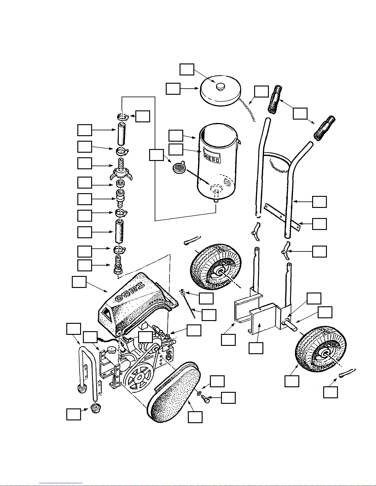
1100MD SCHEMATIC
2
7
12
8
9
10
12
7
12
11
12
1
4
14
5
14
13
13
13
13
14
14
14
11
11
11
H.E.R.O. INDUSTRIES LTD. 1100MD OWNERS MANUAL - “B” VERSION
14
32
13
14
58
12
12
13
57
13
12
13
Page 34
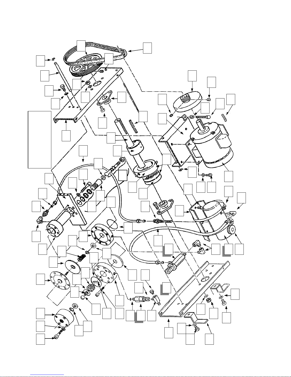
PARTS SCHEMATICS
59 14
11
11
10
10
94
57
93
58
Model 1100MD
92
91
10
10
10
11
10
10
10
11
11
“B” Version
10
60
55
56
54
87
98
99
89
90
97
88
86
96
63
95
11
10
54
67
66
10
68
64
52
51
49
53 61
46 14 15 16
H.E.R.O. INDUSTRIES LTD. 1100MD OWNERS MANUAL - “B” VERSION
48
47
23
22
21
18
17
50
25
28
40
27 26
20
24
32
31
33
69
70
45
43
93
44
58
10
57
10
14
94
10
65
62
58
Page 35
AUTHORIZED SALES AND SERVICE
CENTERS - U.S.A.
Call H.E.R.O.’s Toll Free Helpline 1-800-464-HERO (4376) or take your unit to your nearest
authorized H.E.R.O. dealer. Help is available to answer all your sales and service questions, weekdays
from;
7:00 AM-4:30 PM ( Pacific Time ). After hours calls are recorded and returned the next business day.
þ Full Parts and Service ý Parts Only Sales
Bentley Co. Inc.
4109 Airport Way, South
Seattle, WA 98108
Phone: (206) 622 -8262
Fax: (206) 622-1736
West Central:
Janco Airless Center
1235 5th Street,
Berkeley, CA 94710
Phone: (510) 527 -2842
Fax: (510) 527-5166
Master Airless
10235 Sepulveda Blvd
Mission Hills, CA 91345
Phone: (818) 894 -8085
ALABAMA
Triplett Paint & Decorating,
1800 Wilmer Ave.,
Anniston, AL 36201
205-236-5601
Alabama Airless Supply,
939 Jackson Blv d.,
Birmingham, AL 35217
205-849-9100
Mobile Paints
1002 Putman Drive, N.W.,
Huntsville, AL 35805
205-837-4930
Abatement Equipment
Rental,
3654 Halls Mill Road,
Mobile, AL 36693
205-661-7329
ALASKA
D.J.’s Alaska Rental,
405 Boniface Parkway,
Anchorage, AK 99504
907-337-2552
Polar Supply,
5001 Eagle Street,
Anchorage, AK 99504
907-563-5000
North West:
South West:
Northpole Building Supplies,
3501 Lathrop Street,
Fairbanks, AK 99701
907-451-8939
Columbia Paint,
35551 Spur Highway,
Soldotna, AK 99669
907-262-4674
ARKANSAS
( See Missouri )
ARIZONA
JP’s Color Center,
415 S. Main Street,
Cottonwood, AZ 86326
602-634-3880
Heath’s Paint Center,
2905 N. Fourth Street,
Flagstaff, AZ 86001
602-779-0355
Phoenix Spray, þ
16601 N. 25th. Avenue,
Phoenix, AZ 85023
602-548-9848
Spraco þ
2218 N. 27th Ave.,
Pheonix, AZ 85009
602-269-1868
North Central:
M & E Equipment,
271 Neil Avenue,
Columbus, OH 43215
Phone: (614) 224 -5858
Toll Free: 800-643-2615
Fax: (614) 224-4029
Central:
Wieburg Enterprises Inc
Rte. 2, Box 310
Camdenton, MO 65020
Phone: (314) 346 -3129
Toll Free: 800- 93 -SPRAY
Fax: (314) 346-4622
South Central:
Bob Taylor Spray
5700 James Avenue
Fort Worth, TX 76134
Phone: (817) 551 -1525
Spray Technology,
1730 W. 10th. Place, Ste. 8,
Tempe, AZ 85281
602-820-3572
Piston Power,
107-3600 S. Palo Verde,
Tucson, AZ 85713
602-792-2101
NORTHERN
CALIFORNIA
Redding Paint Mart,
3101 East Street,
Anderson, CA 96007
916-365-2116
Warehouse Paint,
431 Grass Valley Hwy,
Auburn, CA 95603
916-885-7914
Janco Airless,
1235 5th Street,
Berkeley, CA 94710
510-527-2842
Valley Airless, þ
4021-1 California Ave.,
Carmichael, CA 95608
916-944-2153
Paint Mart,
1431 Mangrove Avenue,
Chico, CA 95926
916-891-0400
Chris’ Fuller Paint,
638 G Street,
Davis, CA 95616
916-756-4187
Elk Grove Paint,
9097 Elk Grove Blvd.,
Elk Grove, CA 95624
916-686-8536
Ponderosa Paint,
3663 N. Clov is Ave.,
Fresno, CA 93727
209-291-0664
Modesto Color Center,
607 Tully Road,
Modesto, CA 95355
209-521-5693
A-Arrow Rentals Sales,
6132 Foothill Blvd.,
Oakland, CA 94605
510-569-0681
Paint Mart,
4435 Antelope Blvd.,
Red Bluff, CA. 96080
916-527-5636
North East:
Essex-Silver-Line Corp.
1118 Lakeview Avenue
Dracut, MA 01826
Phone: (617) 957-2116
Toll Free: 800-451-5560
Fax: (617) 957 -6989
East Central:
American Airless
7986 Suite C, Highway 85 South
Riverdale, GA 30274
Phone: (404) 477-1337
South East:
Atomizers Inc.
6166 - 15th St. E, at Old Hwy 31
Bradenton, FL
Phone: (941) 751-5455
Fax: ( 941) 751-5741
Toll Free: 800-523-5042
Redding Paint Mart,
2330 Larkspur,
Redding, CA 96001
916-221-7688
Power Rentals & Sales,
210 W. Market,
Salinas, CA 93901
408-424-2966
B & T Spray Equipment, ý
45 Elmira Street,
San Francisco, CA 94124
510-467-0170
Empire Paint,
1003 - 3rd. Street,
San Rafael, CA 94901
415-457-0102
Sonoma Paint Center, ý
815 W. Napa,
Sonoma, CA 95476
707-996-6756
Contract Coatings Corp.,
706 E. Main Street,
Stocton, CA 95202
209-465-2634
Tracy Color Center,
84 W. 11th,
Tracy, CA 95376
209-835-9720
Airless Repair Center,
814 Starburst Court,
Windsor, CA 95492
707-838-4580
All Season Paint,
1041 Main Street,
Woodland, CA 95695
916-662-3244
North Valley Paint,
741 Plumas Street,
Yuba City, CA 95991
916-674-1770
SOUTHERN
CALIFORNIA
Decratrend Paint,
1620 East Ball Road,
Anaheim, CA 90805
714-535-8810
Golden State Paint Corp.,
111 South 1st. Avenue,
Arcadia, CA 91006
213-681-9241
San Luis Paint, ý
8120 El Camino Real,
Atascadero, CA 93422
805-466-2226
H.E.R.O. INDUSTRIES LTD. 1100MD OWNERS MANUAL - “B” VERSION
34
Page 36

AUTHORIZED SALES AND SERVICE CENTERS- U.S.A.
SOUTHERN
CALIFORNIA
Bakersfield Paint,
401 Sumner Street,
Bakersfield, CA 93305
805-327-8431
Diefel’s Paint,
1030 Alta Vista,
Bakersfield, CA 93305
805-325-7201
Sequoia Paint Company,
700 Baker,
Bakersfield, CA 93305
805-323-7948
State Paint Comp any Inc.,
ý
3920 W. Magnolia,
Burbank, CA 91505
818-845-3745
Decratrend Paint,
68 - 845 Perez Road,
Cathedral City, CA 92234
619-324-4615
A-1 Equipment Sales,
19034 E. Arrow Highway,
Covina, CA 91722
818-967-4388
Covina Paints,
924 Citrus Avenue,
Covina, CA 91722
818-331-0069
Center Paint, ý
11153 W. Washington,
Culver City, CA 90230
213-870-6977
Decratrend Paint,
5171 Lincoln Avenue,
Cypress, CA 90630
714-995-1711
Spectra-Tone,
9635 - 43 Klingerman
Street,
S. El Monte, CA 91733
818-442-7269
Richard A. Cole Enterprises,
10551 Bolsa Avenue,
Garden Grove, CA 92643
714-554-9582
Scotch Paint, ý
555 West 189th Street,
Gardena, CA 90248
213-329-1259
San Luis Paint,
592 Grand Avenue,
Grover City, CA 93433
805-489-5606
Universal Paint Center,
101 E. Florida Avenue,
Hemet, CA 92343
714-658-5130
Mr. Paint,
7391 Warner,
Huntington Beach, CA
92647
714-847-4332
17401 Nichols, Unit F,
Huntington Beach, CA
92647
714-847-2392
Lancaster Paint,
43639 10th Street W.,
Lancaster, CA 93534
805-942-6612
San Luis P aint,
407 Ocean,
Lompoc, CA 93436
805-736-3838
A. Shelbourne Co.,
1200 Oregon Blvd.,
Long Beach, CA 90806
310-436-7755
Painters Warehouse,
11941 Exposition Blvd.,
Los Angeles, CA 900604
310-820-3336 / 310-8264576
Sprayco Service Center,
1198 S. La Brea Avenue,
Los Angeles, CA 90019
213-934-5669
San Luis Paint,
950 Los Osos Valley Road,
Los Osos, CA 93402
805-528-5006
Master Airless,
10235 Sepuleda Blvd.,
Mission Hills, CA 91345
818-894-8085
San Luis Paint,
3230 Mian Street,
Morrow Bay, CA 93442
805-772-1209
Scotch Paint,
26871 Hobie Circle, Ste.
A5,
Murrieta, CA 92362
714-677-9498
All Color Paint,
1424 Holt,
Ontario, CA 91762
714-391-1435
Paint Bucket,
1051 W. Holt Blvd.,
Ontario, CA 91761
714-983-2664
Decratrend Paint,
817 Ventura Blvd. ,
Oxnard, CA 93030
805-485-9556
Palm Spring Paint, ý
410 S. Indian Ave.,
Palm Springs, CA 92262
619-325-7466
Decratrend Paint,
2180 E. Walnut,
Pasadena, CA 91107
818-793-5807
Spectra Paint Center,
Pasadena, CA 91107
818-793-5155
Tim’s Airless Equipment,
2304 E. Colorado Blvd.,
Pasadena, CA 91107
818-793-7087
San Luis Paint,
611 Creston Road,
Paso Robles, CA 93446
805-238-5467
Redlands Paint,
1390 Industrial Avenue,
Redlands, CA 92374
714-798-0750
Redlands Paint,
555 W. Redlands Blvd.,
Redlands, CA 92373
714-793-2488
A. Shelbourne Company,
1440 - 3rd Street, Unit 9,
Riverside, CA 92501
714-784-9410
Decratrend Paint,
116 W. Base Line,
San Bernardino, CA 92410
714-888-3211
Frazee Paint
6625 Miramar Road,
San Diego, CA 92121
619-276-9500
San Luis Paint,
3490 Broad Street,
San Luis Obispo, CA
93401
805-543-1206
Decratrend Paint,
516 State Street,
Santa Barbara, CA 93101
805-962-3140
San Luis Paint,
407 S. Blosser,
Santa Maria, CA 93454
805-928-7995
Lehne & Sons,
1625 - 17th Street, #2,
Santa Monica, CA 90404
213394-6463
Decor Paint Center,
2844 Thousand Oaks
Blvd.,
Thousand Oaks, CA 91362
805-495-7097
Golden State Paint,
23134 Normandie,
Torrance, CA 90502
310-530-9000
Spectra Paint Center,
7615 Balboa Blvd.,
Van Nuys, CA 91406
818-786-5610
Tim’s Airless Equipment,
7353 Van Nuys Blvd.,
Van Nuys, CA 91405
818-785-9423
San Luis Paint,
2424 E Main Street,
Ventura, CA 90091
805-641-1375
Altura Paint,
1850 Hacienda Drive,
Vista, CA 92083
619-724-3600
West Whittier Paint,
11408 E. Whittier Blvd.,
Whittier, CA 90601
213-692-7214
COLORADO
All Seasons Rent All,
2157 S. Haven,
Aurora, CO 90014
303-755-3566
Don’s Airless Repair,
819 Hoorne Avenue,
Colorado Springs, CO
80907
719-635-0632
Vern’s Airless,
3730 Paris Street,
Denver, CO 80239
303-373-1636
Mayer Paint Service,
4410 Yates,
Denver, CO 80212
303-433-9393
CONNECTICUT
Ray Roth Paint,
16 Beaver Brook Road,
Danbury, CT 06810
203-792-6662
Brandman & Sons,
173 Main Street,
Norwalk, CT 06851
203-847-3885
DELEWARE
( See New Jersey, Rhode
Island, Pennsylvania )
FLORIDA
Atomizers Inc.
6166 - 15th St. E,
Bradenton, FL
Phone: 941-751-5455
Fax: 941-751-5741
Toll Free: 800-523-5042
Clewiston Paint Center, ý
307 E. Sugarland Highway,
Clewiston, FL 33440
813-983-9496
Southern Paint & Supply,
239 South Segrave,
Dayton Beach, FL 32014
904-253-8107
Destin Paint Center,
343 Highway 98 East,
Destin, FL 32541
904-837-4141
Devoe & Raynolds,
3300 N.W. 9th Avenue,
Fort Lauderdale, FL 32503
305-563-5934
1320 N.W. 23rd Avenue,
Fort Lauderdale, FL 33311
305-581-6060
Paint Store Plus, ý
11485 S. Cleveland Avenue,
Fort Myers, FL 33907
813-939-0541
The Paint House,
1218 Orange Avenue,
Fort Pierce, FL 34950
407-465-5862
Pintexs Chemical Co mpany,
642 - 660 W. 84th Street,
Hialeah, FL 33014
305-558-5731
Briton’s Paint,
200 Park Street,
Jacksonville, FL 32211
904-354-7707
Devoe & Raynolds,
1406 Hendricks Avenue,
Jacksonville, FL 32207
904-398-0511
Classic Paints Inc.,
1610 Cypress Drive,
Jupiter, FL 33469
407-746-6569
Color Wheel Paint,
284 N. Wickman Road,
Melbourne, FL 32935
305-262-3222
Color Wheel Paint, All Pro,
2714 Silver Star Road,
Orlando, FL 32808
407-293-6810
Devoe & Raynolds,
1121 N. Mills Avenue,
Orlando, FL 32803
904-253-8107
Panhandle Paint Supply,
327 E. 15th Street,
Panama City, FL 32401
904-265-8373
Air Tool Company Inc.,
4112 N. Davis,
Pensecola, FL 32401
904-438-3225
Color Wheel Paint,
A6 - 3866 Prospect Avenue,
Riviera Beach, FL 33404
407-844-1232
Scott Paint, All Pro,
7839 Fruitville Road,
Sarasota, FL 34240
813-371-0002
Devoe & Raynolds Paint,
3102 W. Kennedy Blvd.,
Tampa, FL 33609
813-877-5841
Atomizers Inc.,
Tampa, FL 33614
813-873-2866
Mercury Spray Equipment,
5241 G New Peachtree
Road,
Chamblee, GA 30341
404-451-4856
United Tool Rental,
3509 Highway 120,
Duluth, GA 30136
404-476-8665
Gainesville Paint,
528 Bradford Street,
Gainesville, GA 30501
770-532-3146
Acme Paint,
1979 Riverside Drive,
Macon, GA 31201
912-743-9336
American Airless,
7986 Highway 85 S.,
Riverdale, GA 30279
770-477-1337
J & S Sales and Service,
1070 - 6 Windy Hill Road,
Smyrna, GA 30081 - 2595
770-435-3464
Devoe & Raynolds,
1841 Mountain Indust.
Blvd.,
Tucker, GA 30084
404-938-2006
Pacific Rent - All, ý
1080 Kilauea Avenue,
Hilo, HI 96720 - 4296
808-935-2974
Decratrend Paints,
220 Puuhale Road,
Honolulu, HI 96819
808-842-3802
Hawaiian Rent All, ý
1946 S. Beretania Street,
Honolulu, HI 96826
808-949-3961
Pacific Paint,
2865 Ualena Street,
Honolulu, HI 96819
808-836-3142
Kapaa Paint Supply,
4516 Kukui Street,
Kauai, HI 96746
808-822-1788
A - 1 Hawaiian Rentals, ý
325 Hanakai Street,
Kahului, HI 96732 - -2406
808-877-7684
Toolmaster Hawaii,
3061 Aukele Street,
Lihue, Kauai, HI 96766
808-245-8885
Ponderosa Paint, All Pro,
GEORGIA
HAWAII
IDAHO
H.E.R.O. INDUSTRIES LTD. 1100MD OWNERS MANUAL - “B” VERSION
35
Page 37

AUTHORIZED SALES AND SERVICE CENTERS- U.S.A.
Boise, ID 83705
208-336-7210
Ponderosa Paint, All Pro,
4631 Aeronca Street,
Boise, ID 83705
208-376-4431
Broadway Paint & Glass,
1305 Broadway,
Boise, ID 83706
208-345-1581
State Paint & Glass,
4774 W. State Street,
Boise, ID 83703
208-336-7210
Caldwell Paint & Glass,
916 Cleveland Blvd.,
Caldwell, ID 83605
208-459-0838
Nampa Paint & Glass,
816 - 3rd. Street S.,
Nampa, ID 83651
208-466-3547
ILLINOIS
Spray Systems Specialists,
172 W. Devon,
Bensenville, IL 60106
708-860-2722
Twin Cities Paint,
1202 E. Port Drive,
Bloomington, IL 61704
309-663-9148
Calumet Paint,
12120 S. Western Avenue,
Blue Island, IL 60406
708-371-2240
Brown’s Paint & Glass,
119 N. Walnut,
Champaign, IL 61820
217-352-4149
Neer’s Paint,
620 - 6th. Street,
Charleston, IL 61920
217-345-2320
A. Allin & Son, ý
4839 N. western Avenue,
Chicago, IL 60625
312-561-9800
Ambassador Paint, ý
5101 N. Lincoln Avenue,
Chicago, IL 60625
312-561-6276
Decorator’s Supply House,
4019 W. 63rd. Street,
Chicago, IL 60629
312-735-9700
Paulson’s Paint,
5514 N. Milwaukee Ave,
Chicago, IL 60630
312-763-7337
WM Thybony Co.,
5440 N. Clark Street,
Chicago, IL 60640
312-561-2275
Frank’s House of Color,
219 W. Main Street,
Danville, IL 61832
217-442-0381
Diamond Paint,
1795 Oakton,
Des Plaines, IL 60018
708-824-8084
Premier Coatings,
2250 Arthur Avenue,
Elk Grove, IL 60007
708-439-4200
Barron’s Paint,
207 Barron Blvd.,
Grays Lake, IL 60030
708-223-3020
G.L. Supply - Rental Dist.
20 N. 9th. Avenue,
Melrose Park, IL 60160
708-338-9717
Danny’s “The One Stop” ,
4975 Route 71
Oswego, IL 60543
708-554-3155
Kiem’s Paint Center, ý
4002 Blackhawk Road,
Rock Island, IL 61201
309-786-0066
Friedman’s Paint, ý
1105 S. Grand Avenue,
Springfield, IL 62703
217-544-3461
INDIANA
Behren’s Paint Spot,
219 E. 14th. Street,
Anderson, IN 46018
317-642-0246
J.H. Coble,
1621 S. Jefferson Street,
Huntington, IN 46750
219-356-5028
Quality Paint Center,
815 N. Deleware Street,
Indianapolis, IN 46204
317-632-8219
Bartholomew’s Inc., ý
1331 S. Michigan Avenue,
South Bend, IN 46618
219-289-5509
IOWA
Klinger Paint,
333 - 5th Avenue S.E.,
Cedar Rapids, IO 52406
319-366-4996
Paint Pump Pro,
3410 S.W. 9th St.,
Des Moines, IA 50315
515-244-3611
Diamond Vogel Paint,
Industrial Air Park,
Orange City, IO 51041
712-737-4993
KANSAS
Allied Paints,
2818 Cage Blvd.,
Topeka, KS 66614
913-272-5644
KENTUCKY
Hikes Point Paint,
3041 Breckenbridge Lane,
Luisville, KY 40220
502-451-2226
LOUISIANA
Joseph Paint & Wallpaper,
95 Bolton Avenue,
Alexandria, LA 71301
318-443-8443
MAINE
( See Massachusetts )
MARYLAND
Jim’s Airless,
5815 Arbor Street,
Tuxedo, MD 20781
410-792-2643
MASSACHUSETTS
Essex Silver Line Corp.,
( Rental Distributor )
1118 Lakeview Avenue,
Dracut, MA 01826
617-957-2116
Natick Airless Inc.,
19 Willow Street,
Natick, MA 01760
508-653-0808
Town Paint, ý
41 Meetinghouse Lane,
Sagamore, MA 02563
617-888-8237
Paint Project,
584 Waverly Street,
Framingham, MA 01701
508-879-4578
MICHIGAN
Central Paint Supply,
G4424 Corunna Road,
Flint, MI 48504
313-732-4464
O’Leary Paint, All Pro,
415 Baker Street,
Lansing, MI 48910
Starr Paint & Decorating,
735 Brookside Dri ve,
Lansing, MI 48917
517-323-7152
The Paint Center,
2038 Harbor Petosky Road,
Petoskey, MI 49770
616-348-5969
Michigan Industrial Paint,
29740 Parkway,
Roseville, MI 48066
313-774-4700
Westside Decorating,
3505 State Street,
Saginaw, MI 48602
517-793-6182
Paint Can,
2674 Orchard Lake Road,
Sylvan Lake, MI 48503
313-682-2820
Lincoln Distributing,
26060 Northline,
Taylor, MI 48180
313-946-4010
Paint Pro,
4686 Dixie Highway,
Waterford, MI 48329
810-673-3707
MINNESOTA
Lathrop Paint,
4360 Lyndale Avenue N.,
Minneapolis, MN 55412
612-521-7127
Hamernich Glass & Paint,
1381 Rice Street,
St. Paul, MN 55117
612-487-3211
MISSISSIPPI
( See Alabama )
MISSOURI
Wieburg Enterprises,
Rte. 2, Box 310,
Camdenton, MO 65020
800-93-SPRAY ( 7779)
Johnston Paint & Decorating ý
613 E. Ash Street,
Columbia, MO 65201
314-443-8755
Darco Equipment Service,
6519 Stadium Drive,
Kansas City, MO 64129
816-924-1245
Zeke’s - Kasey Paint, ý
1224 Swift N.,
Kansas City, MO 64116
816-842-4540
Strothkamp Bros., ý
14390 Manchester Road,
Manchester, MO 63011
314-227-5225
Hydraflow Equipment,
8125 Brentwood Industrial
Dr.,
St. Louis, MO 63144
314-644-6677
MONTANA
Columbia Paint,
2019 Grand Avenue,
Billings, MT 59102
406-252-0048
Columbia Paint,
2020 West Babcock,
Bozeman, MT 59715
406-586-1356
Columbia Paint,
2045 Harrison,
Butte, MT 59701
406-723-3200
Columbia Paint,
435 First Street,
Havre, MT 59501
406-265-2702
Columbia Paint,
East 925 Lyndale,
Helena, MT 59601
406-443-2086
Columbia Paint,
3316 - 10th Avenue South,
Great Falls, MT 59405
406-761-6174
Columbia Paint,
865 West Idaho,
Kalispell, MT 59901
406-785-7815
Columbia Paint,
1509 Russell,
Missoula, MT 59801
406-549-6111
NEBRASKA
Ron’s Paints Inc., ý
13315 B Street,
Omaha, NE 68144
402-334-1715
NEVADA
Painters Warehouse,
1022 S. Main Street,
Las Vegas, NV 89101
702-384-3820
Paint Sprayers Unlimited,
3129 S. Highland,
Las Vegas, NV 89109
702-731-5688
Wright’s Paint & Paper,
959 W. 5th Street,
Reno, NV 89503
702-322-2320
Dr. Bob’s Airless Systems,
5390 A. Riggins Court,
Reno, NV 89502
702-826-5900
Nevada Air & Indust.
Equip.,
1001 Greg Street,
Sparks, NV 89431
702-355-1600
NEW HAMPSIRE
( See Massachusetts )
NEW JERSEY
( Also see Pennsyvannia )
Painten Place Inc.,
Rte. 53 & a. & P. Shop
Ctr,
Denville, NJ 07834
201-627-4050
Cougar Electronics &
Repair,
622 Broadway,
Long Branch, NJ 07740
908-870-3302
NEW MEXICO
Wellborn Pai nts,
215 Rossmoor Road S.W.,
Albuquerque, NM 87105
505-877-5050
NEW YORK
Buffalo Airless,
4216 Clinton Street,
Buffalo, NY 14224
716-675-7979
R.H. Miller Paint, All Pro,
1681 Route 9,
Cliffton Park, NY 12065
518-465-1526
Aboff’s Inc.,
410 New York Avenue,
Huntington, NY 11743
516-427-2000
Zelf Tool,
44 Greene Street,
Manhattan, NY 10013
212-925-8586
Empire Paint,
5 State Street,
Pittsford, NY 14534
716-385-5510
The Paint Bucket,
3970 Merrick Raod,
Seaford, NY 11710
516-785-0332
Lewis & Tanner,
430 E. Washington Street,
Syracuse, NY 13202
315-476-8351
NORTH CAROLINA
Myers Service & Dist. Inc.,
1204 Commercial Avenue,
Charlotte, NC 28205
704-334-3333
Johnson’s Repair Center,
3120 Cleveland Road,
Clayton, NC 27520
919-934-4726
OHIO
Midwest Spray Inc.,
4515 Reading Road,
Cincinnati, OH 45229
513-242-4500
M & E Equipment Service,
271 Neil Avenue,
Columbus, OH 43215
614-224-5858
OKLAHOMA
( See Texas, Kansas or
Missouri )
OREGON
Ashland Paints,
1618 Ashland,
Ashland, OR 97530
503-482-4002
Miller Paint Company,
8703 S.W. Beaverton
Hillside Highway,
Beaverton, OR 97005
503-292-4444
H.E.R.O. INDUSTRIES LTD. 1100MD OWNERS MANUAL - “B” VERSION
36
Page 38

AUTHORIZED SALES AND SERVICE CENTERS- U.S.A.
Denfeld Paint,
1851 N.E. 2nd Street,
Bend, OR 97701
503-382-4171
Miller Paint Company,
2811 N.W. Grant,
Corvallis, OR 97330
503-758-4458
J’s Color Center,
1986 W. 6th Avenue,
Eugene, OR 97402
503-345-2397
Tommy’s Paint Pot,
1745 W. 11th Avenue,
Eugene, OR 97402
503-683-5851
Jon’s Airless Spray,
8225 N. Applegate Road,
Grants Pass, OR 97527
503-862-2680
Miller paint Company,
1831 W. Powell Blvd.,
Gresham, OR 97080
503-666-9018
Medford Paint Center
1160 Hilton,
Medford, OR 97501
503-773-8295
Helfrich Equipment Co.,
435 N.E. Tillomook,
Portland, OR 97212
503-288-6761
Miller Paint Company,
317 S.E. Grand Avenue,
Portland, OR 97214
503-233-4491
Portland Compressor Inc.,
310 S.E. 12th Avenue,
Portland, OR 97214
503-235-0200
Salem Paint,
702 Hi gh Street,
Salem, OR 97301
503-364-5631
Miller Paint Company,
548 High Street N.E.,
Salem , OR 97301
503-364-2264
Pacific Pa int & Decorating,
11852 S.E. Pacific Hwy,
Tigard, OR 97223
503-620-7522
Miller Paint Company,
19355 S.W. Mohave Court,
Tualitin, OR 97062
503-691-1200
Oregon Spray Equipment,
19360 S. W. 90th Court,
Tualatin, OR 97062
503-692-7266
PENNSYVANNIA
Hydraulic Industrial Supply
Holly & Madison Avenue,
Clifton Heights ( Philly ),
PA 19108
610-284-2100
H.E.R.O. INDUSTRIES LTD. 1100MD OWNERS MANUAL - “B” VERSION
SprayFix,
120 S. Easton Road,
Glenside, PA 19038
610-886-1571
Airdraulics,
555 W. Ansbury Street,
Philadelphia, PA 19140
610-457-1940
RHODE ISLAND
New England Paint, ý
51 Higginson Avenue,
Central Falls, RI 02863
401-722-4672
SOUTH CAROLINA
Rainbow Paint & Paper,
118 Greenacre Road,
Greenville, SC 29607
803-232-1463
Hilton Head Paint,
6 Southwood Park,
Hilton Head, SC 29925
803-681-6357
Pelican Paint,
69 Matthews Drive,
Hilton Head, SC 29928
803-681-9600
SOUTH DAKOTA
Direct Paint,
1/2 mile W. on Highway 34
Madison, SD 57042
605-256-4114
TENNESSE
Parrish Equipment Service,
3828 Clarksville Highway,
Nashville, TN 37218
615-242-7525
TEXAS
Monarch Pa int, All Pro,
801D Secretary Drive,
Arlington, TX 76015
817-795-1000
E.A.H. Spray Equipment,
2125 F. Goodrich,
Austin, TX 78704
512-447-0165
Monarch Paint, All Pro,
9230 Neils-Thompson,
Austin, TX 78758
512-837-0267
Monarch Paint, All Pro,
3905 Warehouse Row,
Austin, TX 78704
512-443-4877
Paint Warehouse,
2907 Vila Maria,
Bryan, TX 77803
409-822-5599
Monarch Paint, All Pro,
1225 Crosby Road,
Carrollton, TX 75006
214-245-0666
Metroplex Spray Equipt,
123-2332 Joefield Road,
Dallas, TX 75229
Monarch Paint, All Pro,
600 Benbrook Parkway,
Fort Worth, TX 76126
817-249-6888
Bob Taylor Spray,
5700 James Avenue,
Fort Worth, TX 76134
817-551-1525
E.A.H. Spray Equipment,
901 Ashland,
Houston, TX 77008
713-869-6594
Monarch Paint, All Pro,
10125 Epsom,
Houston, TX 77093
713-695-6624
Monarch Paint, All Pro,
9911 Honeywell,
Houston, TX 77036
713-772-2925 or 772-3551
Monarch Paint, All Pro,
3530 Lang Road,
Houston, TX 77092
713-462-5373
Painter’s Hardware Corp.,
2001 Karback, Suite Q.,
Houston, TX 77092
713-956-2073
Painter’s Repair Shop,
14919 Steubner-Airline
Road,
Houston, TX 77069
713-537-2468
Advanced SprayTech,
2150 Wren,
Lewisville, TX 75067
214-446-2222
Monarch Paint, All Pro,
5848 - 49th Street,
Lubbock, TX 79424
806-797-1200
Monarch Paint, All Pro,
5334 Spencer Highway,
Pasadena, TX 77505
713-487-6416
Monarch Paint, All Pro,
1791 Millard Drive,
Plano, TX 75074
214-881-0402
Monarch Paint, All Pro,
7445 Tower Street,
Richland Hills, TX 76118
817-595-1000
E.A.H. Spray Equipment,
1318 BAsse Road,
San Antonio, TX 78212
512-734-3105
Monarch Paint, All Pro,
6816 Alamo Down, # 4,
San Antonio, TX 78238
512-647-8831
Monarch Paint, All Pro,
145 - 12200 Crown Road,
San Antonio, TX 78233
512-656-5541
37
1619 Spring Cypress,
Spring, TX 77373
713-353-3020
Monarch Paint, All Pro,
2611 N. Beltline,
Sunnyvale, TX 75218
214-226-9200
Bartek’s Paint & Decorating,
2602 W. Avenue North,
Temple, TX 76501
817-771-0010
UTAH
Jones Paint & Glass,
170 N. 100 West,
Provo, UT 84641
801-373-3131
Robert Taylor & Sons,
381 Ironwood Drive,
Salt Lake City, UT 74115
801-486-1335
Jim’s Airless Repair,
5032 Shooting Star Avenue,
West Jordan, UT 84084
801-967-1224
VERMONT
( See Massachusetts or
New York )
WEST VIRGINIA
( See Ohio or
Pennsylvannia )
VIRGINIA
( See Pennsylvannia or
North Carolina )
WASHINGTON
Parker Paint, ý
29 - D Street S.E.,
Auburn, WA 98002
206-833-2656
Parker Paint, ý
156th & 8th N.E.,
Bellevue, WA 98008
206-746-1559
Hardware Sales Inc.,
2034 James Street,
Bellingham, WA 98225
360-734-6140
Parker Paint, ý
18004 Bothell Way N.E.,
Bothell, WA 98011
206-486-9116
Parker Paint, ý
5930 Evergreen Way,
Everett, WA 98203
206-353-0220
Parker Paint, ý
32900 Pacific Hwy South,
Federal Way, WA 98003
206-838-8090
Parker Paint, ý
19500-D Highway 99 S.
W.,
Lynnwood, WA 98036
206-778-6622
Parker Paint, ý
Redmond, WA 98052
206-885-7858
KM Spray Equipment, All
Pro,
6349 - 6th Avenue S.,
Seattle, WA 98108
206-762-8060
Bentley Co. Inc., ý
4126 Airport Way South,
Seattle, WA 98108
206-622-8262
CZS Enterprises,
5221 Ballard Avenue N.
W.,
Seattle, WA 98107
206-783-8835
Miller Paint Co.,
1500 N.W. Leary Way,
Seattle, WA 98107
206-784-7878
Parker Paint,
2924 - 4th Avenue S.,
Seattle, WA 98108
206-467-8981
Universal Repair Shop,
1611 Boylston Avenue,
Seattle, WA 98122
206-322-2726
Parker Paint, ý
10600 Silverdale Way N.,
Silverdale, WA 98383
206-692-7766
Columbia Paint Co, All
Pro,
North 112 Haven Street,
Spokane, WA 99202
509-327-3323
In WA. 800-826-1715
Out WA. 800-231-0372
Spokane Pump,
3626 E. Trent,
Spokane, WA 99202
509-535-9771
Parker Paint,
3326 South Junette,
Tacoma, WA 98411
206-473-1122
Miller Paint Co.,
2607 N.E. Andresen,
Vancouver, WA 98661
206-854-3434
Pacific Power Tool Repair,
12814 N.E. Hwy 99,
Vancouver, WA 98686
800-444-6605
WISCONSIN
Parker Coatings,
2451 W. Mason,
Green Bay, WI 54307
414-494-9676
Hallman-Lindsay Paint,
7326 W. North Avenue,
Wauwatosa, WI 53213
414-453-1972
WYOMING
( See Montana, Idaho )
Page 39
MANUFACTURED BY:
H.E.R.O. INDUSTRIES
2719 LAKE CITY WAY
BURNABY, B.C.
CANADA
PHONE: 604-420-6543
800-494-4376
FAX: 604-420-8725
PURCHASED FROM
__________________________
__________________________
__________________________
__________________________
MODEL: __6-1100MD-LA__
SERIAL #: _________________
DATE OF PURCHASE:
________________
H.E.R.O. INDUSTRIES LTD. 1100MD OWNERS MANUAL - “B” VERSION
38
 Loading...