

Page 1
● ARCHIMEDE
● A100/A150
Automatic Colourant Dispenser
USER MANUAL
Page 2

2
Declaration of Compliance with CE Regulations
HERO EUROPE S.r.l.
Fraz. Buretto, 12/A
12041 – Bene Vagienna (CN)
ITALY
Declares that:
The Automatic Dispenser model: ARCHIMEDE A100-A150
Serial number:________
Is in compliance with the EC Machinery Directives:
Machinery Directive 98/37/EEC
Low tension 73/23/EEC
Electromagnetic Compatibility 89/336/EEC
Is in compliance with the standardized European Regulations:
EN 292-1, EN 292-2, EN 418 & EN 1050
EN 60204-1
EN 61000-6-2, EN 61000-6-3, EN 61000-3-2 & EN 61000-3-3
HERO EUROPE S.r.l. Alessandro Sacchet
Fraz. Buretto, 12/A
12041 – Bene Vagienna (CN) Chairman
ITALY HERO EUROPE S.r.l.
Page 3

3
A100-A150 Automatic Dispenser Key
Canisters and covers
Electronic control
board (open the
front panel)
Colourant
dispensing nozzles
Can loading
Nylon shelf for
positioning the paint
Page 4

4
General Conditions
By choosing the ARCHIMEDE A100-A150 automatic colourant dispenser manufactured by
HERO EUROPE, you have selected a product which represents the result of intensive
research in the field of high-tech fluid dispensing equipment. Top quality materials, modern
designing tools such as the use of CAD three-dimensional parametrical systems, together
with the attention given to ergonomics, guarantee an easy to use, long lasting machine.
The dispenser is in compliance with the 89/392/EEC directive regarding machinery, the
89/336/EEC directive regarding electromagnetic compatibility, as well as the 73/32/EEC
directive regarding electrical equipment to be used within a specific voltage range
compiled by the European Community Council of Ministers, and is provided with the EC
trademark.
The handbook explains how to install a HERO EUROPE automatic dispenser and provides
all the necessary information in order to insure easy use and proper maintenance.
It is very important to read the manual carefully and completely before completing
any task on the dispenser.
The dispenser uses progressive cavity volumetric pumps to dispense colourants for the
purpose of tinting paint either sequentially (A100) or simultaneously, up to 4 colourants
(A150). Do NOT run the pumps, either manually or automatically, if there is no
colourant in the canisters. Should this occur, the pumps will be irreparably
damaged.
The maximum allowable time between agitation cycles is 36 hours.
Always follow the recommended maintenance procedures and schedule to ensure the best
possible operation of the dispenser. Where and when appropriate, these procedures
should be completed by duly authorized and trained personnel. For optimum performance
the dispenser needs to be installed and operated within the following guidelines:
· Room temperature: 15-40°C
· Relative humidity: 30-90%
The dispenser must be connected to a dedicated electrical outlet with an appropriate
ground.
Failure to comply with the above listed requirements will invalidate the dispenser’s
warranty.
For technical assistance, please contact the vendor’s Customer Service department.
This handbook should be kept in a safe place
Page 5

5
Warranty Terms
The ARCHIMEDE A100-A150 automatic dispenser terms of warranty are summarized as
follows:
1. HERO EUROPE provides a one year warranty on the correct functioning of the
products supplied, except for break downs due to normal usage. If a breakdown is
not covered by the warranty, the customer will be charged for the inspection,
implemented by HERO EUROPE, to determine whether the breakdown is covered
by the warranty or not. Should the breakdown be covered by the warranty, HERO
EUROPE will deliver an identical or equivalent product. The terms of warranty,
herein described, apply only if the products supplied by HERO EUROPE are used
in compliance with what is stated in the manual. The labour necessary to complete
the work related to the warranty, together with transfer time, travel, meals and
accommodation expenses will be calculated according to current rates.
2. HERO EUROPE is not obligated to honour the terms of the warranty if:
a. The product was repaired or attempted to be repaired by the customer or by
a third party without the proper authorization from HERO EUROPE, unless
HERO EUROPE previously refused to repair the product at a reasonable
price;
b. HERO EUROPE demonstrates that no defect was detected after testing;
c. The customer did not immediately and correctly communicate the breakdown
to HERO EUROPE, when possible, in writing and/or via fax, and/or did not
carefully follow HERO EUROPE’s instructions;
d. The customer used or treated the product incorrectly or differently to what
was established by HERO EUROPE;
e. The damage was originated by circumstances that occurred during transport
or installation and cannot be verified by HERO EUROPE.
3. Henceforth, the word “program” will refer to the standard computer program that
HERO EUROPE has put at the customer’s disposal, based on computer software
and relevant documents (Software handbook), including any improved or updated
versions. The word “PC” refers to the machine to which the program is associated
and should solely be used in relation to such program.
4. The customer has the right to copy the program partially or completely (up to a
maximum of two copies) for internal security reasons; the copies must bear the
same trademarks, indications pertinent to copy right and any other identification
marks present on the original version of the program.
5. The customer does not have the right to modify, translate, decode or adapt the
program to its original code unless specific written consent is granted by HERO
EUROPE. Furthermore, if requested by the customer, HERO EUROPE must
provide information on how to obtain effective program interfacing with other
software.
Page 6

6
6. In case of a PC breakdown, the customer has the opt ion to install the program on
another PC until the original PC is repaired, however, HERO EUROPE must be
notified within 5 days.
7. In case of a PC break down, the PC manufacturer’s terms of warranty will be
considered valid, even if the PC was supplied by HERO EUROPE.
8. Should there be a need to install the program on another PC, the customer must
ask HERO EUROPE to provide written consent, which cannot be refused on
unreasonable grounds.
Page 7

7
Safety Instructions
Please read the instructions carefully before installing and operating the dispenser, as a
personal safety measure as well as to avoid needless damage to the equipment.
HERO EUROPE declines any responsibility should the following instructions not be
followed:
• Do not turn on a damaged machine (for example, if the machine is damaged during
transportation). If in doubt, first contact the service department or the reseller.
• Position and connect the machine by carefully following the installation instructions
and by respecting the conditions stated in this manual.
• All the instructions and local safety regulations must be observed.
• The machine must only be connected to a wall electrical socket installed according
to regulations, with the grounding circuit and the voltage value in compliance with
what is written on the machine’s information plate.
• The user must maintain the machine in good working condition and replace any
broken components.
• Any service on the machine, other than routine, can only be carried out by a
qualified technician. Make sure that the power cable is not plugged into the
socket while the machine is being repaired.
• A standard machine is solely suited to dispensing water-based colourants into
standard paint cans.
• The elastomeric parts inside the dispensing circuits could be damaged if other
thinners, i.e., solvent-based colourants are used.
• Never run the pumps without colourant in the respective canister, otherwise the
friction within the pumps will lead to an increase in temperature capable of
damaging the pumps.
Page 8

8
Machine Positioning and Installation
Instructions for correct positioning
Be certain to respect the following details while positioning the machine:
• Place the machine on a steady, horizontal surface by using a level.
• The area must be well ventilated. To avoid drying of colourants, make sure the
machine is not exposed to the sun or near heaters or any other source of heat.
• The surrounding temperature should be kept as constant as possible, around 18°C
(and always between 15 and 40°C) so as to prevent variations in the specific weight
and viscosity of the colorants.
• Make sure the machine is connected only to a wall socket installed according to
regulations, with its grounding circuit and voltage value in compliance with what is
written on the machine’s information plate.
Machine unpacking
• Remove the external nylon film from the package
• Remove the fastening straps placed around the outside of the packaging box
• Remove the packaging box by lifting it above the unit
Pallet removal and machine positioning
Due to its weight, between 62Kg and 72Kg, this must be done by a minimum of two
persons. Place the machine where it is intended to be put to use.
Page 9
9
Computer and Monitor Assembly
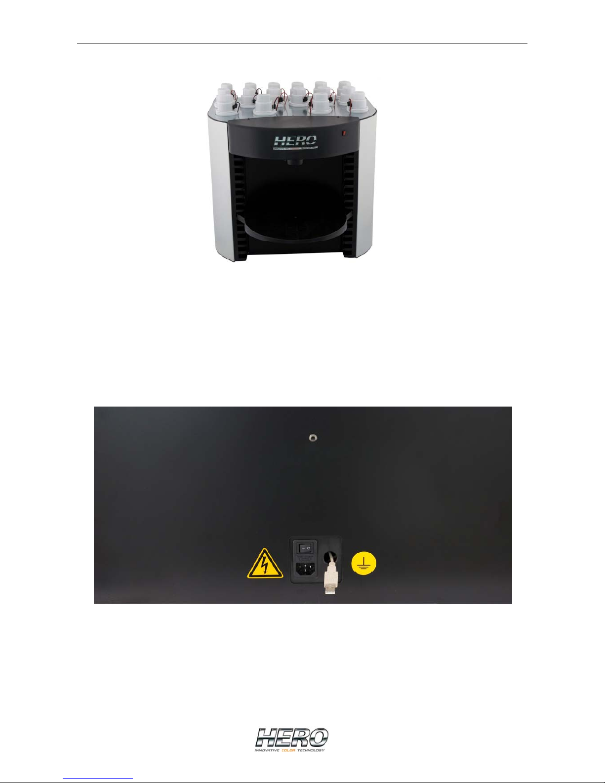
After having positioned the PC, you must connect it to the electronic card that commands
and controls the dispenser. In order to do so, you will find a USB connecting cable
included inside the package.
On one side, connect the USB cable to the appropriate socket positioned on the electronic
card in the dispenser and on the other side, connect it to one of the USB sockets on the
PC. The USB port on the PC will be configured correctly by installing the software provided
with the dispenser.
Page 10

10
Starting the Dispenser
Connect the AC power cords of the dispenser and the PC to a wall socket (refer to
“General conditions” and “Safety instructions” sections) then turn on the PC.
By following the instructions in the software handbook, install the software on the PC.
Load the colourants into the canisters but be careful not to overfill.
Complete the following procedure to load the colourants:
• Disconnect the power plug to the agitation motor on the lid of the canister that you
intend to fill.
• Remove the lid.
• Fill the canister, but be very careful not to spill any colourant on the central part of
the agitation paddles.
• Replace the lid once the canister has been filled. Make sure the lid is closed
properly.
• Reconnect the power plug to the lid.
After having loaded all the canisters, the calibration procedure must be completed before
being able to use the machine.
A precision scale is necessary to accomplish the calibration procedure.
Please refer to the software handbook for instructions regarding calibration.
Page 11
11
Canister Replacement
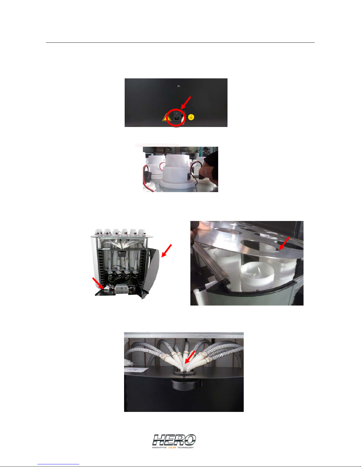
WARNING: Ensure that the machine is turned off
• To disconnect the machine’s power supply, pull the power plug out of the socket
• Disconnect all the cables from the covers and remove all the covers
• Remove the upper front cover of the nozzle assembly, the canister plate that
surrounds all of the canisters and open the front panel
• Pull the appropriate nozzle away from the dispense head
Page 12
12
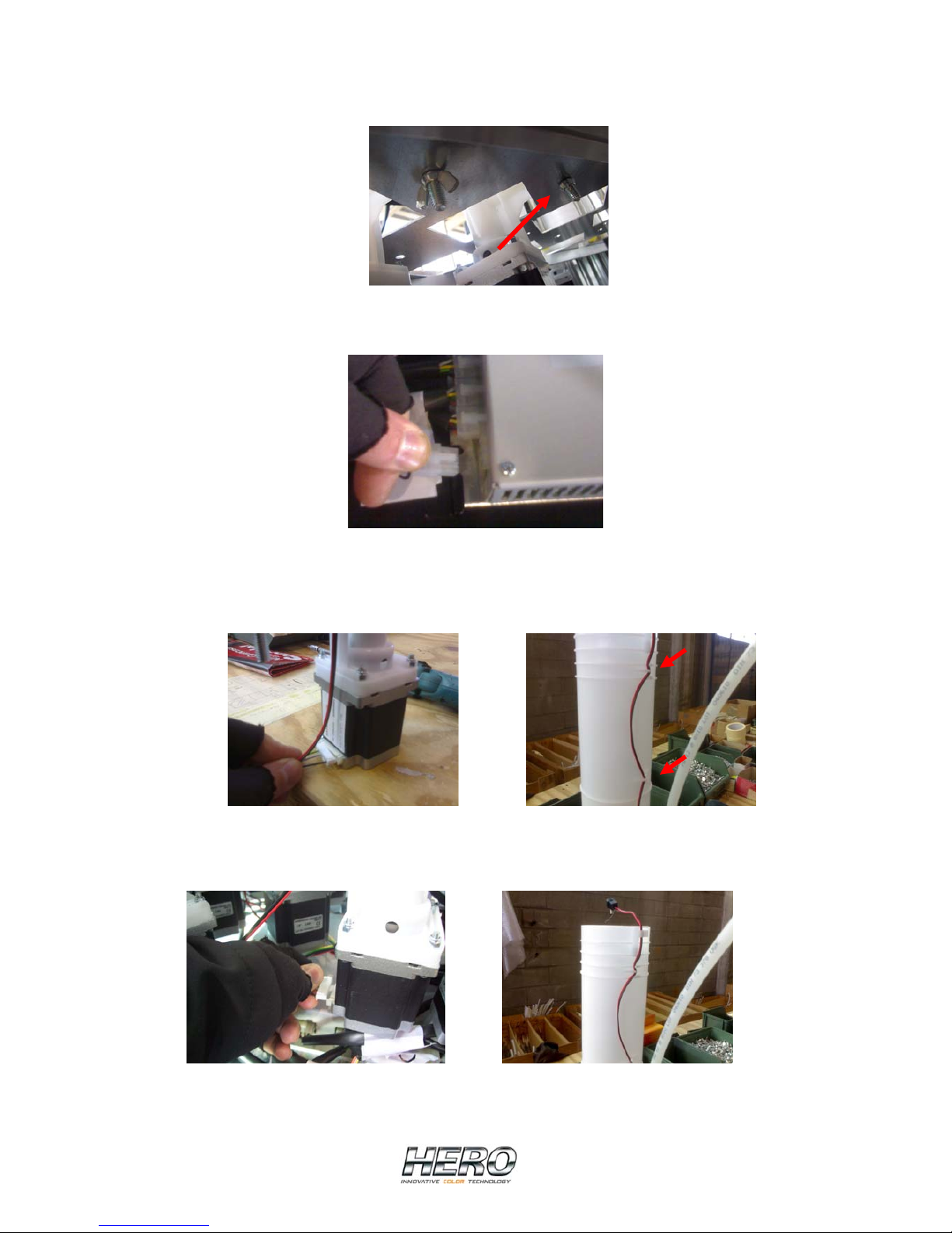
• Remove the wing nut that holds the canister, located under the lower canister
support plate
• Disconnect the canister power c able from the electronic board and pull the canister
away from its seating
• Disconnect the cable connector from the electric stepper motor lo cated in the lower
part of canister and pull the thin agitation cable out of its hooks on the side of the
canister
• Connect the cable to the electric stepper motor of the new canister and insert the
cable into its hooks on the canister
Page 13
13
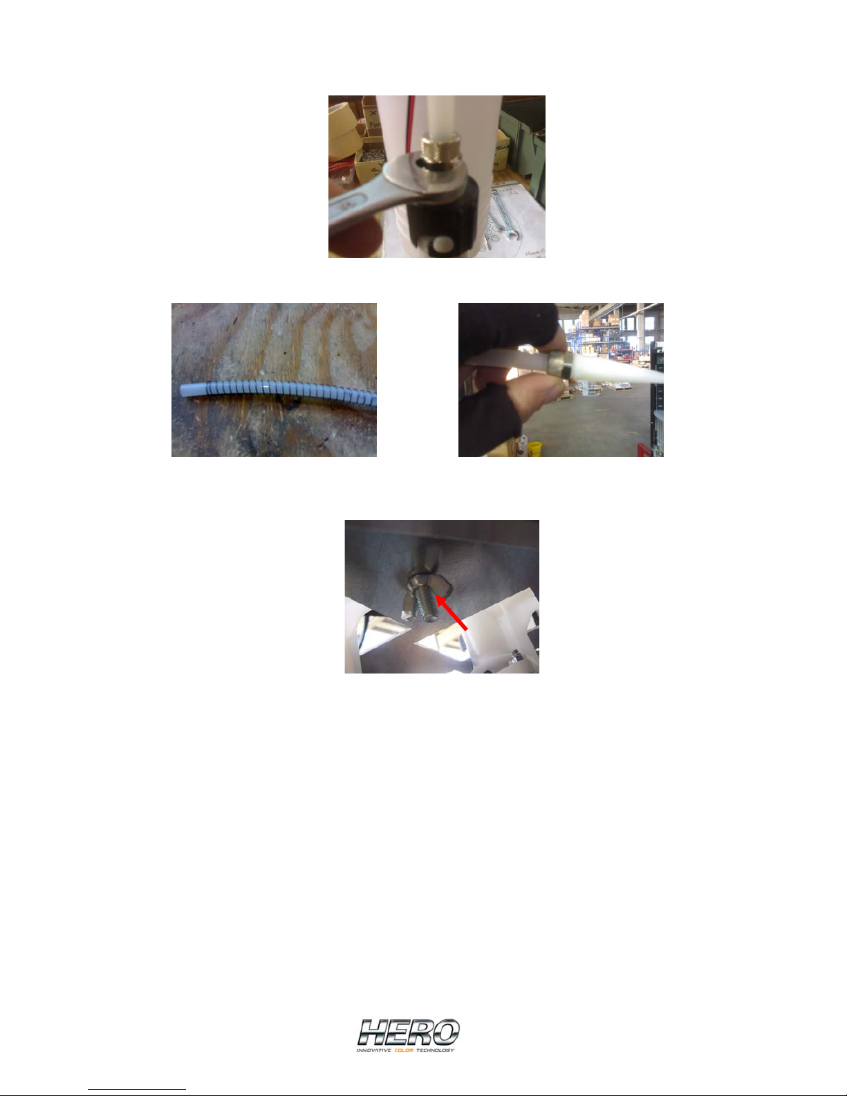
• Cut the tubing at the proper length and attach it on the canister by screwing the
metal ring nut on the nipple
• Insert the spring and screw the other stainless steel nut onto the nozzles
• Put the new canister in its appropriate place and lock it in place by tightening the
wing nut
• Insert the nozze into the dispense head
• Reconnect the cable to the electronic board
• Replace the upper canisters plate
• Replace the upper front cover of the nozzle assembly
• Place the lids on the canisters and reconnect the cables
• Close the front panel
• Add colourant to the new canister
• Start the canister’s pump through the Manual Commands screen in order to release
the air which is present within the new tubing and pump. Continue the process until
a solid flow of colourant comes out of the nozzle
Page 14
14
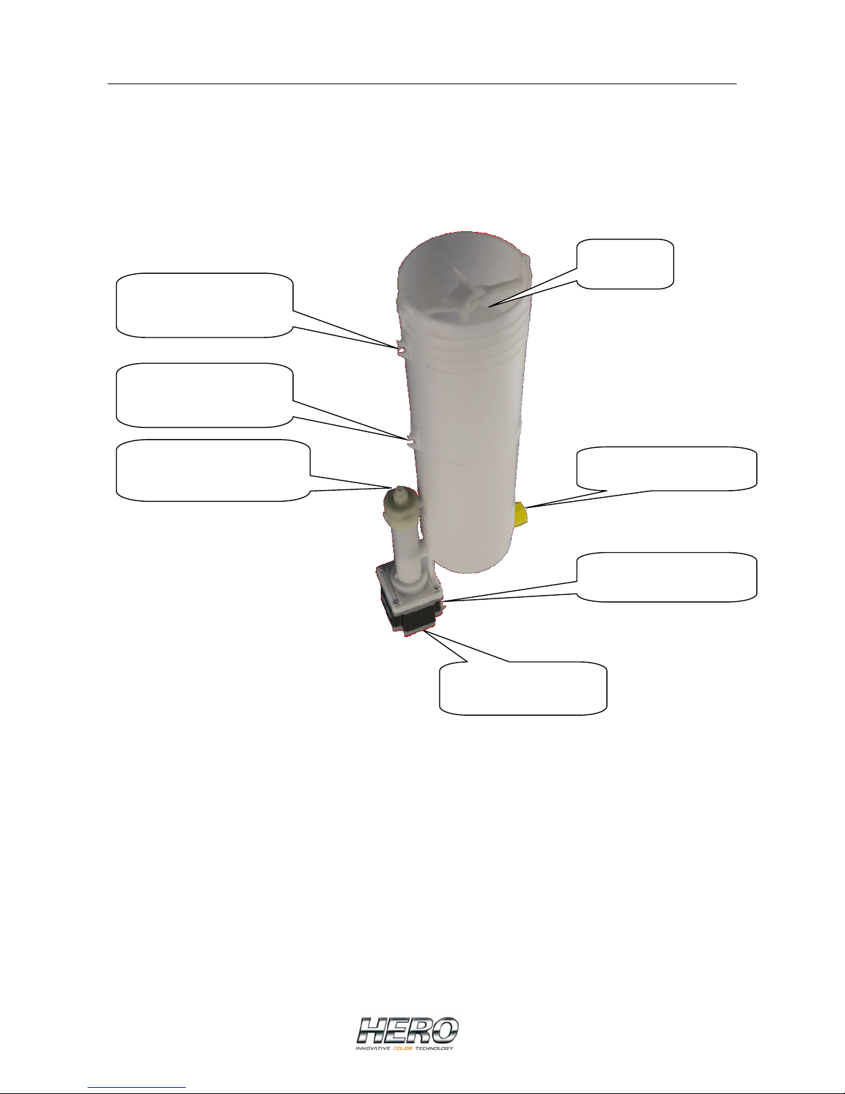
Canister/Pump/Stepper Motor Assembly
Canister drain plug
Stepper motor
connector
Electric stepper
motor
Pump nipple
Hook for agitation
motor power cable
Agitation
paddle
Hook for agitation
motor power cable
Page 15
15
Power Supply Replacement
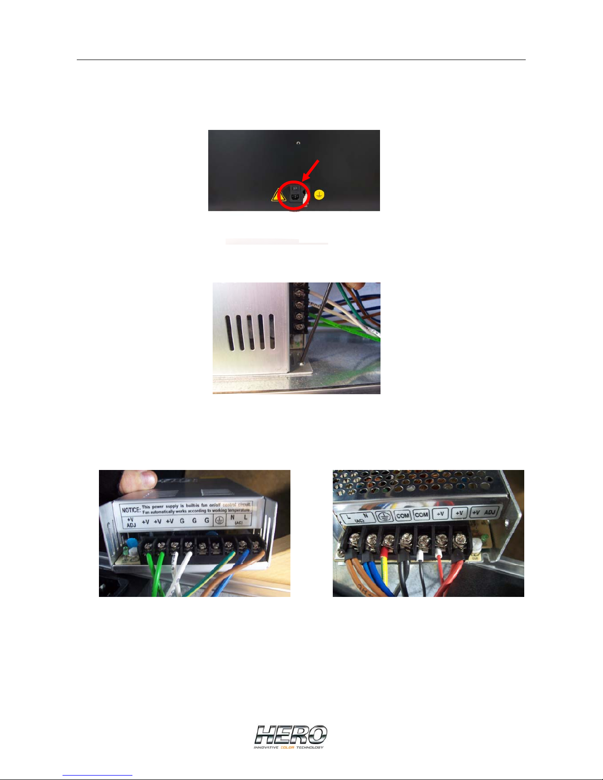
WARNING: Ensure that the machine is turned off
• To disconnect the machine’s power supply, pull the power plug out of the socket
• Remove the rear cover
• Remove the screws on the sides of the power supply with a wrench
• Remove the power supply, take note of which colored wire is connected to which
terminal and disconnect the wires
• Install the new power supply ensuring that each wire is connected to the correct
terminal
67VDC 24VDC
• Secure the new power supply to the machine with the original screws
• Replace the rear cover
Page 16
16
Simultaneous Control Board Replacement
(USA market)
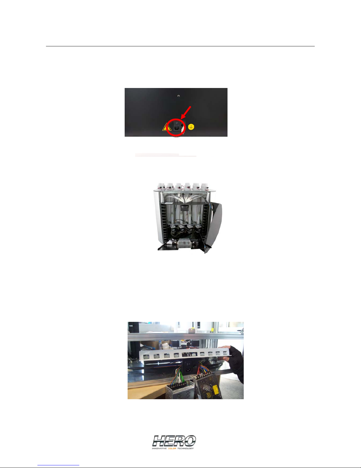
WARNING: Ensure that the machine is turned off
• To disconnect the machine’s power supply, pull the power plug out of the socket
• Remove the rear cover
• Remove the power supplies without disconnecting the cables
• Remove the upper front cover of the nozzle assembly and open the front panel
• Disconnect the cables to the canister lids and remove the lids
• Remove the upper canister plate that surrounds all of the canisters
• Remove all of the canisters in the last row on the rear of the machine and in the first
row on the front
(see “Canister Replacement” page 11)
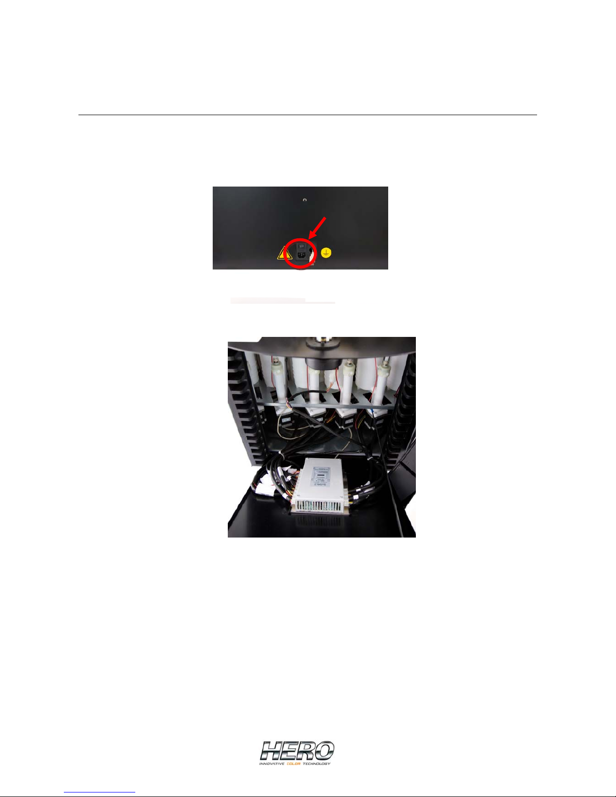
• Pull out all of the connectors from the electronic board
• Remove the four screws holding the control board to the bottom of the unit
• Take the electronic board out from the rear of the machine
• Place the new electronic board and secure it with the screws
Page 17
17
• Connect the cables following the number markings on the board and on the cables
• Replace the rear cover
Sequential Control Board Replacement
WARNING: Ensure that the machine is turned off
• To disconnect the machine’s power supply, pull the power plug out of the socket
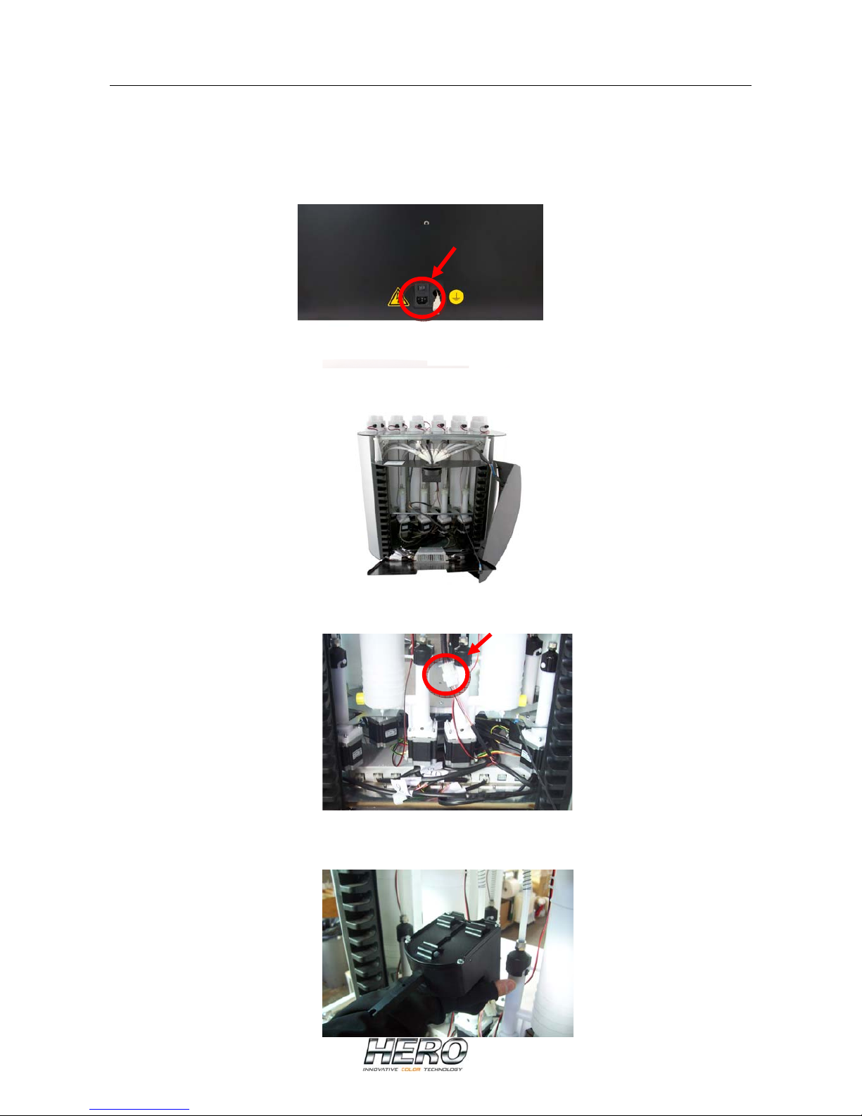
• Open the front panel by removing the screws
• Disconnect all the cables and remove the electronic board
• Install the new electronic board and connect the cables following the number
markings on the board and on the cables
Page 18
18
Automatic Cap Replacement
WARNING: Ensure that the machine is turned off
• To disconnect the machine’s power supply, pull the power plug out of the socket
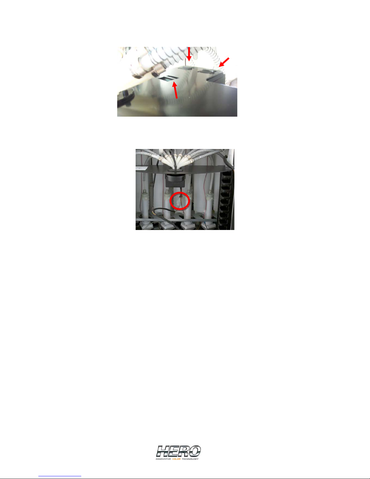
• Remove the upper front cover of the nozzle assembly and open the front panel
• Unplug the connector on the harness that leads to the cap
• Pull forward (towards you) on the complete cap assembly or housing to release it
from the chassis
Page 19
19
• Install the new cap by inserting it into the proper slots on the chassis
• Connect the cable from the cap to the appropriate wiring harness
• Replace the upper front cover of the nozzle assembly and close the front panel
Page 20
20
Automatic Cap
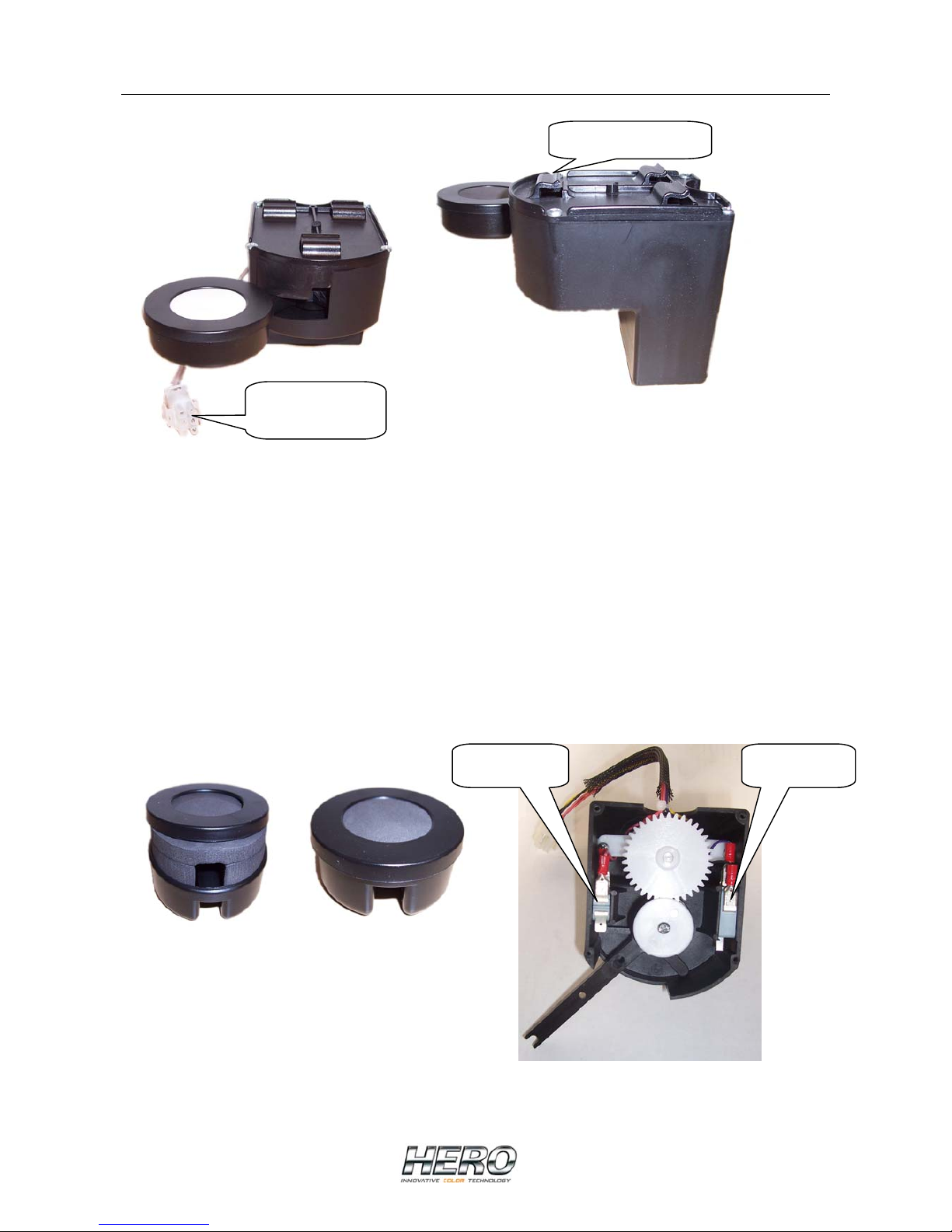
The dispenser is equipped with an automatic cap,
that helps prevent the drying of colourants in the
nozzles. The “pull back” function within the
software parameters must be set correctly, to avoid problems of contamination or dripping
of colourants. The cap opens automatically before each dispense and also closes
automatically after dispensing; with this device the possibility of colourants drying in the
nozzles is greatly reduced. The part of the cap containing the sponge is easily removed to
facilitate cleaning, as shown in the pictures below.
Inside the cap housing there are two micro-switches that control the two positions of the
automatic cap; closed and opened. The automatic cap was designed to be replaced easily
and quickly. To replace, unplug the power supply connection and pull the cap towards the
front of the dispenser; the attachment hooks will release and the cap will slide out. Now the
new automatic cap can be installed and connected without using any tools.
It is very important to keep the sponge clean and wet to allow for proper and
trouble-free dispensing, so it is advised that the sponge be cleaned and kept wet on
a regular basis.
Power supply
connection
Attachment hooks
Cap closed Cap open
Page 21

21
Equipment Specifications
Description: ARCHIMEDE A100-A150 Automatic Colourant Dispenser
Capacity: Up to sixteen (16) 2.5lt canisters
Pumps: Each canister is fitted out with a progressive cavity pump.
The pump rotors are made of metal treated with a
hardening chroming so as minimize wear. The stators are
made of Viton elastomer. The materials used for the
pumps are compatible with water-based colourants.
Pump speed: Variable and to be established depending on the
colourants and ambient conditions. Maximum speed is
0,2 litres/min.
Nozzle cleaning: Colourant pull-back system after dispensing, to minimize
drying of colourants in the nozzles. Automatic humidifying
cap.
Canister agitation: Each canister is provided with a lid that includes a motor,
which rotates agitation paddles inside the canister.
Can sensor: Reflection-photocell detects the can on the shelf.
Power supply: Variable from 110 to 240 Volts AC with a 50 or 60 Hz
frequency.
Dimension: Height 600 mm
Width 700 mm
Depth 540-610 mm
Weight 141-161 Kg
Package size:
ARCHIMEDE A100-12 780 x 600 x 870 (h)
ARCHIMEDE A150-12 780 x 670 x 870 (h)
ARCHIMEDE A100-16 780 x 670 x 870 (h)
ARCHIMEDE A150-16 780 x 670 x 870 (h)
Page 22

22
Suggested Spare Parts
• Complete canister/stepper motor assembly
• Canister lid with agitation motor
• 3 m of flexible tubing for outlet lines from pumps to nozzles
• Set of nozzles (8 pieces)
• Canister power cable
• Electronic board
• Power supplies (24VDC and 67VDC)
Page 23
23
Troubleshooting Guide
The following chart listing “Problem”, “Cause” and “Solution” should be consulted before
requesting service.
When in doubt, please contact HERO EUROPE S.r.l.’s service department before any
attempts are made to repair the equipment.
PROBLEM
CAUSE
SOLUTION
Colourant leaks from the flange
connecting the pump motor to the
canister
Broken pump
Canister replacement
Colourant dripping from the
nozzle
• Air in the circuit
• The pull-back function
parameters are not set
correctly
• Purge the circuit until you
see a regular colorant
flow, free from air bubbles
• Program the pull-back
function parameters
correctly
When dispensing ends the
colorant goes back towards the
canister through the nozzle thus
emptying the tubing
Worn pump
Canister replacement
During operation, the circuit
dispenses in a noisy, irregular
way
• The cable connecting the
electronic card and the
pump motor is not
plugged in correctly
• The cable connecting the
electronic card and the
pump motor is damaged
• Motor has broken down
• Electronic card is not
working
• Stalled pump
• Check that the cable
between the electronic
card and the motor is
properly connected on
both ends
• Replace the cable
connecting the electronic
card and the motor
• Replace the canister
• Replace the electronic
card
• Start the pump by hand
slowly until it unblocks.
Increase the purging
frequency and if
necessary, thin the
colourant
The sensors don’t work
and/or
The pump motors don’t work
and/or
The mixing motors don’t work
The connection between the PC
and the machine is no longer
functioning
• No power
• The machine’s power
cable is disconnected
• The power cable for the
electronic card is not
plugged in
• A fuse has blown
• Verify that the unit has
power
• Connect the machine’s
power cable to the power
outlet
• Make sure the power
cable to the electronic
card is plugged in
• Replace the fuse
Page 24

24
The pump motor functions
normally, however no colourant
comes out of the nozzle
• No colourant in the
canister
• The canister nozzle is
obstructed
• The pump is damaged
• Add colourant to the
canister and purge the
circuit to remove any air
• Replace the nozzle and
verify that the colourant
has not thickened.
• Replace the canister and
related tubing
The colours are difficult to
reproduce
• The nozzles are dirty
• Different quality of
colourant
• Thickened colourant
• Colorant is leaking from
the circuit
• Temperature is too low
• Circuit’s calibration is
incorrect
• Complete one or more
purges and clean nozzles
• Contact the colourant
supplier
• Replace the colourant
• Substitute the canister
and related tubing
• Increase room
temperature
• Recalibrate the
appropriate circuits
No images on the monitor or the
images are not clear
• Monitor is turned off
• Cables are not plugged in
properly
• Image adjustment is too
dark
• Monitor failure
• Turn on the monitor
• Check all cable
connections
• Set the image up properly
• Replace the monitor
The keyboard and/or the mouse
do not work
• Cables are not plugged in
properly
• Cables are damaged
• Damaged keyboard
and/or mouse
• Wrong set up
• Check all cable
connections
• Replace the cables
• Replace the keyboard
and/or the mouse
• Verify the set up
The agitation process of one or
more canisters does not function
• The cable to the motor is
not well connected
• The agitation motor is
damaged
• The cable is damaged
• The electronic card is
damaged
• Check the cable
connection
• Replace the lid/motor
assembly
• Replace the cable
• Replace the electronic
card
If necessary, please contact HERO EUROPE ‘s service department. When doing so, be
sure to have the machine’s serial number, which can be found on the identification plate
on the back panel of the machine
HERO EUROPE S.r.l.
Fraz. Buretto, 12/A – 12041 Bene Vagienna (CN) – Italy
Tel. + 39 0172 654866
Fax +39 0172 654887
Page 25
25
Standard Parameters
The following chart shows the parameters related to running a machine together with their
respective default values.
PARAMETER
MEANING
DEFAULT VALUE
Mixing – Time ON
Mixing – Time OFF
Mixing time ON
Mixing time OFF
1 min – 0 sec
120 min – 0 sec
Pumps – acceleration
Pump motor acceleration speed
1000
When the value increases
acceleration also increases
Pumps - deceleration
Pump motor deceleration speed
1500
When the value increases,
deceleration also increases
Pumps – Boost time
Time in which the pump motor
receives the maximum power
30 sec
Pumps – Start speed
Pump starting speed
15% (75 r.p.m.)
Canister Page
Dispensing speed
Pump dispensing speed
expressed as a percentage in
regards to the maximum value
60% (300 r.p.m.)
It is possible to set 60% (300
r.p.m. – 0,2 l/min)as a max value
when calibrating
Purging – ml
Ml to deliver during purging
1 ml
Purging - Speed
Pump speed during the purging
phase
25% (125 r.p.m.)
The above value corresponds to
the maximum speed of the step
motor torque
Drip-free device - Steps
Number of pump motor steps
during the phase in which the
drop is “pulled back”
40 (0,1 r. – 0,07 cc)
Drip-free device – Waiting time
Waiting time, after each dispense
has ended, before the drip-free
device phase is implemented
3 sec
Capacity
Canister capacity
2 litres
Page 26
26
Warning level
Below this level you are warned
to fill the canister
0,4 litres
Alarm level
Below this level dispensing is no
longer permitted
0,2 litres
Steps alarm
Number of motor steps possible
before proceeding with a
precautionary substitution
1.013.854.085 steps
(1.760,00 litres)
Purging alarm
Maximum time lapse without
purging, between one dispense
and another of the same
colourant
6 hours
Calibration Page
Drop Calibration
Minimum quantity calibrated
Threshold Calibration
Machine Calibration
The theoretical value of the product moved (pumped) with one complete rotation of the
pump is 0,6944 cc, measured with water at an approximate temperature of 25 °C.
576,05346 steps of the motor are necessary to dose 1cc. This value is programmed in the
dispenser as being the standard calibration value.
Page 27
27
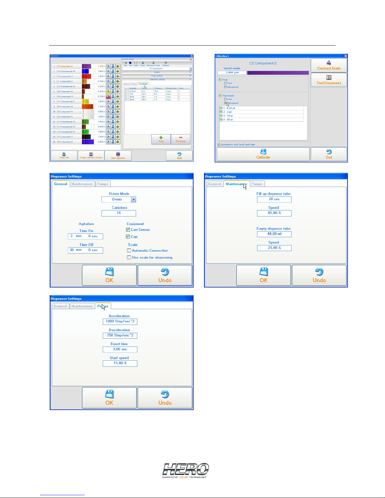
Parameters Images
 Loading...