

HERO ES, 621H, 725H, 621C, 725C Safety And Operating Manual
...
Version 5 Dec 2005
SAFETY A ND OPERATING MANUAL
WARNI NG: DO NOT OPE RATE T HIS EQUIP ME NT WIT HOUT RE ADING
AND UNDERS TAN DING ALL SAFET Y AND OPERATING I NS TRUCTIONS
SEE PAGES 3 – 14
FACTORY LOCATED AT:
720 EATON WAY
DEL TA, B.C. CANADA
V3M 6J9
PHONE : (604) 522-65 43 FAX: (604) 522-8735 TOLL FREE: (800) 494-4376
www.hero.ca
U.S.A ADDRESS:
P.O. BOX 75
CUSTER, WASHINGTON
98240-0075

TABLE OF CONTENTS
PAGE DESCRIPTION PAGE #
Warranty Information 2
Important Safety Precautions 3-4
Introduction and Unpacking 5
Set Up 6
Start Up 7-8
Spray Tip Selection 8-9
Spray Painting Suggestions 10-11
Pressure Relief, Shut Down and Cleaning 12-13
Filter Maintenance 14
Digital Display Troubleshooting and Diagnostics 15-16
Pump Troubleshooting 17
Pump Cartridge and Intake Valve Removal 18-19
Intake Valve Servi ce 19
Intake Valve Servi ce (Old Version) 20
Pump Cartridge Disassembly and Service 21
Pump Cartridge Assembly 22
Prime Valve Service 23
Pump an d Drive Assembly Parts Breakdown 24
Cart Assembly Parts Breakdown 25
Wiring Schematic 26
Parts List and Descriptions 27-30
Airless Accessories 30
Contact Infor mation 31
Owner’s Manual
Page 1
EC621 / E C725
WARRANTY
H.E.R.O. WA RRANTY
H.E.R.O. Products Group, guarantees this airless pump to be free of defects in materials and
workmanship to the original owner, for a period of two (2) full years from the date of purchase.
The warranty entitles the owner to parts replacement at no charge. The parts replacement
warr anty is valid for any necessary replac ement, weat her caused by material or workmanship
defect or simple wear. H.E.R.O. Industries offers no warranty on the hoses, gun, tip or
acce ssories, plastic, rubber, other s oft goods or moto r used in or s upplied w ith the H.E.R.O.
sprayer.
In addition to the general coverage listed above, a lifetime WARRANTY is offered on the Drive
Tr ai n compone nts . The dri v e t r ai n co mp onents are defi ned a s the items conta ine d wit hin, b ut not
including, t he “ Dri ve Hous ing” . Drive mot or i s not inc l uded.
Furthermore, this warranty does not cover, damage or wear caused by faulty installation,
abr asi on, cor rosi on, ina deq uate or impr oper mai ntenanc e, neglig ence, or a cci dent.
Motor, accessories, etc., which are supplied by other manufacturers and are attached to or
supplied with the H.E.R.O. airless pump, are warranted only to the extent that these parts are
warranted by their respective manufacturers. Warranty claims on these items must be made
directly to such manuf acturers or their local authorized service depots.
The w ar ra nty is o nl y ap p lic abl e t o t he or i gi nal p ur c has er and p ro vid ed t he e qui pm e nt ha s be e n
properly used, operated and maintained in accordance with all instructions, precautions and
warnings contained in this manual. For the purpose of this warranty, damage resulting from
accident, abuse, impr oper clean in g, stor age, fire , fl oo d, or Act o f God, is not cov ered.
H.E.R.O.’s liability is limited to replacing parts found to be defective or worn and does not include;
transport ation costs, damag e or ot her expens es of any kind incurred in connect ion w ith the
pur cha s e and us e of this sprayer .
Repairs claimed under wa rranty must be perf ormed by an authorized H.E.R.O. Service Center,
using only genuine H.E.R.O. parts. Parts required under warra nty will be supplied by your local
H.E.R.O. Service Center.
DO NO T re turn war ran ty p arts to fa ctory without auth o rization.
To qualify for the warranty, the warranty card (attached to this page) supplied with this H.E.R.O.
airless pump, must be completed with equipment ser ial number and signed by t he pur c haser,
and postmarked within ten (10) days of purchase.
Owner’s Manual
Page 2
EC621 / E C725

IMPORTA NT SAFETY PRECAUT IONS
IMPORTANT
AS WITH ALL MECHANICAL EQUIPM ENT, PROPER OPERATING AND MAINTENANCE
PROCEDURES ARE REQUIR ED TO KEEP YOUR H.E.R.O. AIRLESS PUMP PERFORMING TO
YOUR SATISFACTION. THE FOLLOWING SAFETY, OPERATING AND MAINTENANCE
Read and understand this manual completely, especially with regard to all safet y p recautions. Read
and fo llow instr uctions on all warni ng labels on yo ur equipme nt. K eep t hese war ning labe ls c lean and
readable at all times. Order new labels from your local distributor or from H.E.R.O. Industries if
needed. This system is capab le o f pro duci ng 3000 ps i (s pray pr essure). T o av o id r upt ure a nd i nj ury
DO NOT operate this pump with components rated less than 3000 psi working pressure (including but
not limi te d to spray guns, hose and connections ). Befo re s ervic i ng, clea ning o r remo v al o f any part,
shut off power and relieve pressure.
Prior to the use of the sprayer, ensure that the grounded continuity between the gun and the sprayer
is maintained. The hose shall be at least 50 feet in length. All hoses, guns, and accessories shall be
suitable for the maximum pressure ( 3000 PSI ). The gun shall be provided with a “Safety” which
locks the trigger in the “OFF” position. DO NOT point the gun at another person or spray at any part
of exposed skin. If there are any special or unique conditions for this machine, they shall be further
noted and addressed and must be followed. The manufacturer shall not be responsible for any loss,
damages, or injury of any kind or nature whatsoever resulting from the use of equipment other than in
strict compliance with the instructions, cautions and warnings contained in this operating and
instruction manual.
Never place fingers near spray tip of gun. Never point gun toward any part of the body, or that of any
other person. Material issuing from the spray tip is at high pressure. If fingers, or any part of the body
are placed near the tip of the spray gun, it is possible that the spray could break the skin and inject
some of the material. If injury does occur, seek immediate medical attention. Inform the doctor
wh at fluid was injected, if the injury is of an injec tion nature. Never treat the situation as a simple
matter. Equipment and chemicals, when used improperly can be dangerous.
I NSTRUCTIONS ARE IMPORTANT.
WARNING
IMPORTA NT SAFETY PRECAUT IONS
NEVER place any part o f the body in f ront of the spray tip or ai m the gun toward a ny pa rt of
the body.
NEVER point the gun toward an y individual.
NEVER treat any i njury as a simp le cut. If i njury does occur, s eek i mmediate medica l atte n-
tion. Inform the doctor what fluid was injected.
NEVER allow another p ers o n to use the sprayer unl ess they ar e thoro ughly trai ned on its op-
eratio n and have read al l safety precauti ons i n this m anua l and a ll saf ety war ning labels at tached to unit.
NEVER use around children.
NEVER attemp t to perform any maintenance or service on any part of the sprayer without first;
1. Shutting the motor switch to OFF.
2. Relieving all pressure in the pump by triggering the gun.
3. Open prime valve to drain.
4. Locking gun trigger in "LOCKED" position, with gun locked closed.
NEVER operate the sprayer without the tip guard complete and in place.
NEVER spray any material in the vicinity of open flam e , pilot lights, electrical outlets or any other
source of ignition.
NEVER spray volatile materials with flash points lower than 140 F (60 C).
Owner’s Manual
Page 3
EC621 / E C725

IMPORTA NT SAFETY PRECAUT IONS
NEVER at tempt to stop any leakage in the paint line or at any fitt ing with your hand or any part of your
body. Immediately s hut off t he unit should leakage occ ur.
NEVER allow the paint hose to become ki nked, or t o touch against rough or s harp surfaces.
NEVER operat e the unit at pres sures higher than the pressure rati ng of the lowest rat ed component in
the system, or the factory preset.
NEVER spray in an enclosed area. The spraying area must be well ventilated to safely remove
chemical vapors.
NEVER operate the unit with worn or damaged accessories, or with accessories other than those
supplied by H.E.R.O. Industries, unless the accessories have been first specifically approved in writing
by H.E.R.O. Industries.
NEVER allow the unit t o be serviced or r epaired anywher e other t han an authorized H.E. R.O. Service
Center, or with other than genuine H.E.R.O. parts or components.
NEVER leave unit unattend ed without first shutting off, triggering the gun to relieve all fl uid press ure, and
setting the trigger lock on gun in "LOCKED" positio n.
ALWAYS follow H.E.R.O. recomme ndations for oper at ion and safety.
ALWAYS set trigger lock on gun in "LOCKED" positio n when not in use.
ALWAYS check connect ions and fittings for t ightness befor e oper at ing the unit.
ALWAYS locate t he unit in a well ventilated area a minim um of 25 f eet from the spray area.
ALWAYS ground the unit, the paint containers, and the object being sprayed to eliminate static
discharge. Ensure that all these object s r emain grounded throughout the entire sprayi ng operation.
ALWAYS use accessories and compo nents approved for at least 3000 psi (wor king pressure).
ALWAYS use accessories and compo nents only supplied by H.E.R.O. Industries.
ALWAYS examine accessories f or wear or damage before operating the unit.
ALWAYS use low est possible pressure whe n fl us hing a nd clea ning the unit , and hold t he gun firmly
against a metal contai ner to r educe the possibilit y o f stat ic d is c har ge .
ALWAYS wear safety glasses when operating the unit.
ALWAYS wear a face f ilter mask when operating the unit.
ALWAYS :
1. Shut the motor switch to OFF.
2. Relieve all pressure in the pump by triggering t he gun away f r om your body .
3. Open prime valve to drain.
4. Lock gun trigger in "LOCKED" position, before att empting to perform any maintenance or ser vice on any
part of the sprayer.
ALWAYS ensure fire extinguishing equipment is readily available and properly maintained in the spray
area.
ALWAYS observe good housekeepi ng and keep the spray area fr ee from obstructions.
ALWAYS be awar e t hat cert ain chem icals may react w ith aluminum, car bide, or other components in the
pump system. Read the ma nufacturer's label o n all materials to be sprayed, and f ollow the manufact urer's
recommendatio ns. I f in doubt, consult your materia l supplier.
ALWAYS replace any damaged airless pai nt hose. A scr at ched, cut or ot herwise damaged o uter sheathi ng
of the paint hose can lead to a rupture. DO NOT attempt t o r epair a damaged hose.
DO NOT A T TEMPT TO OPERA T E THIS M ACHI NE UNT IL YO U HAVE REA D AND UNDERSTO OD ALL
SAFETY PRECA UTI ONS A ND OPERA TING INSTRU CTIO NS. EQUIPMENT A ND CHEM ICA LS
WHEN US E D IMPRO P ERLY , CA N BE DA NGERO US.
Owner’s Manual
WARNING
Page 4
EC621 / E C725
INTRODUCTION & UNPACKING
Congr atulations on your purchase of a n ew H.E.R.O. “E C” s eries airl ess paint sprayer. We are
sure you will enjoy owning and operating your new sprayer. With H.E.R.O. airless spray equipment
yo u will enjo y the f ea t ures and benefits of this air les s . You are spra yi ng paint, not air, and the pai nt
is driven to the painting surface in a clean, fan shaped spray which penetrates all cracks and
co r ners. T o atta in t he se r esults, you m ust adjust t he pressure as low as possib le. We recomm end
that you bec ome famil iar with your H.E.R.O. unit. Discuss with your dealer the useful accessory
items they do offer - various types of tips, extension poles for hard to reach areas, extra hose, etc.
Use of accessory items is often the difference between a good job and an excellent one !
Your H.E.R.O. airless sprayer has been fully tested and carefully packaged to avoid damag e.
It should be carefully examined upon arrival to determine that the unit shows no signs of
freight damage. If any parts are found broken or damaged, immediately contact the
carrier and arrange for an inspection of the concealed damaged. Claims for damage
MUST
responsibility for the safe delivery of merchandise upon pick-up from the shipper.
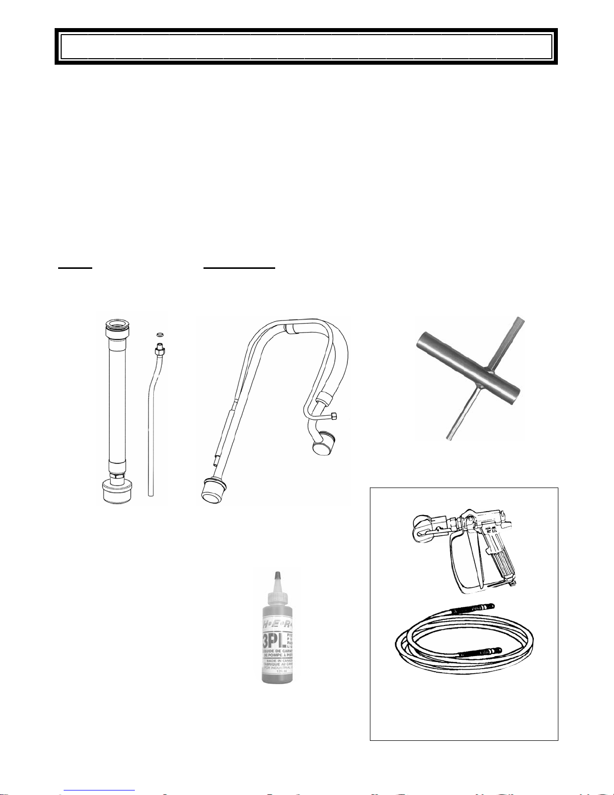
The unit shipping carton contains:
be made by the CONSIGNEE and not the shipper. The carrier accepts full
EC-2600
Siphon Hose Assemb ly
(High Boy model)
EC-2560
Siphon Hose Assemb ly
(Sled and Cart models)
4-02-40-3PL1
Pist on Lub e
(8 Ounce Bottle)
EC-1000
Unitool
(OPTIONAL)
Gun/Hose & T ip Packages
Include: 1/4 x 50Ft Hose, Model 300 or
400 Airless Gun, and 517 Spray Tip
Owner’s Manual
Page 5
EC621 / E C725
SET UP
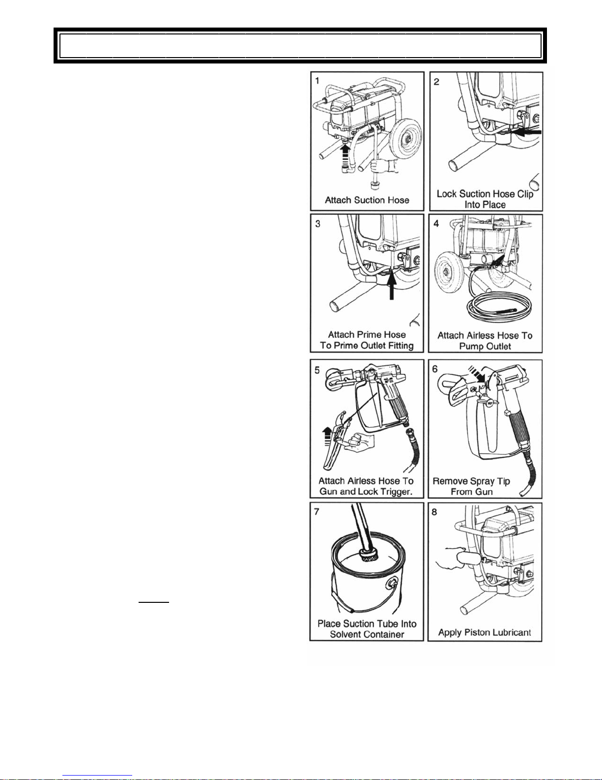
Setting Up:
1. Attach siphon h ose assembly to intake valve
by pulling up intake elbow onto intake valve.
2. Lock clip onto intake valve by sliding clip until
it is locked into its designated slot.
3. Connect prime hose to prime hose outlet
making sure that it is wrench tight.
4. Connect airless hose to pump outlet making
sure that it is wrench tight.
5. Connect airless gun to airless hose making
sure that it is wrench tight an d slide the trigger safety lock up to lock the trigger closed.
6. Remove spray tip from tip guard. This is done
by twisting the tip until it aligns with the tip
guard opening and then by pulling the tip out
of the housing. The tip guard may have to be
loosened to help remove the spray tip. By
removing the tip this will make flushing out
the storage solution safer and easier.
7. Place siphon tube into one gallon of thinner
or flushing fluid. This will be necessary to
flush storage solution from pump. If using a
highly volatile solvent or paint in a metal container it is highly recommended to ground the
container with a grounding wire to ground to
prevent risk of static discharge. If storage solutio n has been fl us hed already wit h thi nner,
then sprayer should be flushed with water if
using water base paints or flushed with correct thinner for oil base paints. Check paint
manufacturer recommendations.
8. Apply packi ng lubrica nt. This will help prevent
buildup of materials on the piston rod thus
extending packing life. To add lubricant, insert pointed nozzle of the 3PL liquid into the
slotted area in the front of the unit. Add only a
small amount . This should be done each
time the sprayer is used. Before each use,
flush the pump with the correct thinner for
the paint being used.
NOTE: The unit MUST
spirits at all times in order to protec t pump from
corrosion and extend pump life.
be stored with mineral
Owner’s Manual
Page 6
EC621 / E C725
START UP
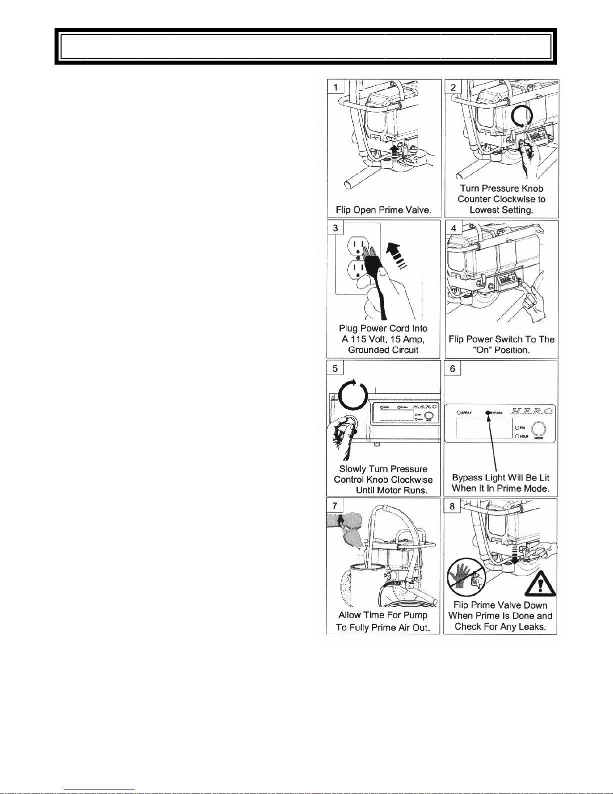
Setting Up (Continued):
1. Flip prime valve lever up to open. This is required to remove air out of the pump.
2. Turn pressure control knob counter clockwise
to lowest set ting. This will cut the power off
until the pressure control knob is turned
clockwise to desired setting.
3. Make sure that the power switch is in the “off”
position and plug the power cord into a 115V,
15 amp., grounded circuit. Note; if using an
extension cord, you must use a #12/3 wire
grounded cord, up to 50 feet or #10/3 wire
grounded cord up to 100 feet. DO NOT EX-
CEED 100 FEET OF EXTENSION CORD. If
distance is greater, purchase and install additional lengths of airless spray hose.
4. Flip the power switch to the “on” position.
5. Slowly turn the pressure control knob clockwise until motor runs.
6. As motor is running with the prime valve
open, the bypass light will be lit to show that
the unit is in prime or “bypass” mode.
7. Allow sufficient time for thinner to circulate
back into the siphon container. It should be
flowing at a constant rate and this may take
seconds to minutes depending on the
viscosity of the paint or flushing fluid.
8. Flip the prime valve lever down to its “closed”
position. The unit should start to build pressure. Check to see if there are any leaks from
any connections. DO NOT attempt to try to
stop any leaks with your hand or with a
rag. If leakage occurs, shut the power switch
to the “off position immediately and flip the
prime valve u p to open and release any remaining pressure. Tighten and recheck connections on all fittings and repeat from step 1.
If no leaks continue to step 9 on page 7.
Owner’s Manual
Page 7
EC621 / E C725
START UP
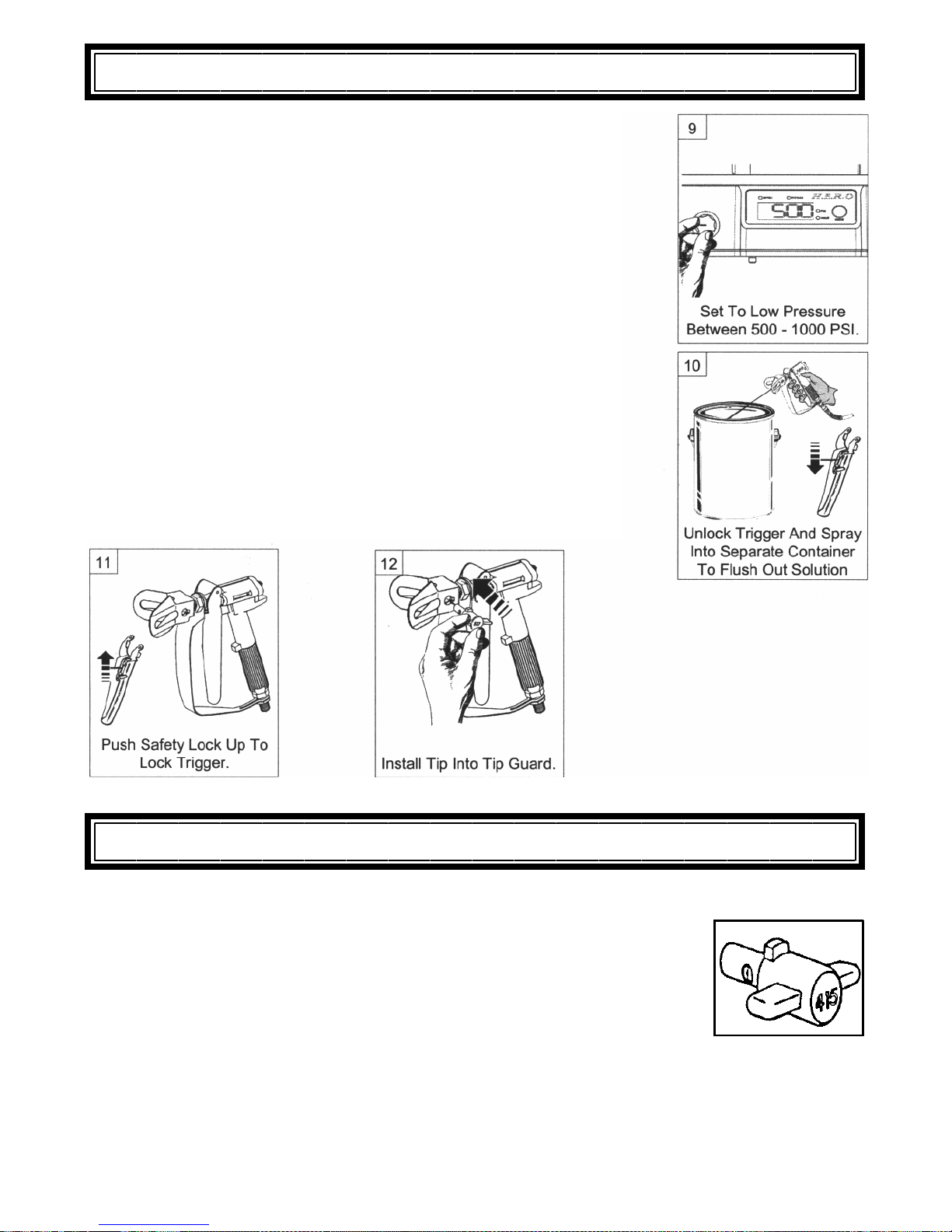
9. The unit should shut off automatically once it reaches its set pressure. At this point keep the pressure set low, between 500 to
1000 psi. The display should now show the pressure and the
spray light should now be lit. This means that the sprayer is under
pressure and ready to spray.
10. Obtain an empty waste container to flush out storage solution.
Unlock gun trigger and trigger into the waste container and
spray until thinner and or paint is flowing out of gun.
11. The storage solution is now flushed from the sprayer and is ready
for spraying. Gun safety trigger should now be locked. If unit has
been flushed previously and paint is ready to spray, then proceed
to step 12. If paint has not been primed though pump then repeat
steps 7 and 8 on set up page and steps 1 to 12 on start up page.
12. In stall spray tip into tip guard. If unsure of which spray tip to use,
refer to spray tip selection chart on page 8.
Please read the next following pages for the pressure adjustment,
spray, maintenance, and troubleshooting instructions.
Hero Flip Tips are coded with three (3) numbers.
To determine the fan size:
1. Double the first number (I.E. : 4 x 2 = 8” i nc h fan wid th) this is d etermined at approximately 12” inches away from the surface.
2. T he last t wo (2) numbers indicat e the o rif ice size i n 1/1000 of an inch.
This is very important as it controls the flow, output of the sprayer, and
overall spray quality.
Owner’s Manual
SPRAY TIP SELECTION
Page 8
EC621 / E C725
SPRAY T IP SELECTION – cont.
Diff erent materials r equire diff erent sizes of tips, and diff erent paint manufactures produce diff erent
qualities o f pai nts. These mate ria ls wi ll ef f ect t he overa l l lif e o f the t ip. I t is v e ry im porta nt to c hoo s e
and monitor the right spray tip. It is advisable to obtain a spray tip recommendation from the supplier
of the material to be sprayed. T he f ollo wing table is a general g uide and will assist in se lecting the
optimum tip to use.
TIP SI ZE USED TYPICALLY FOR SPRAYING THESE MATE-
RIALS
.0 19 Exteri or Latex on large unobstruc t ed are as. .47 White or Green Green - 3 0 Mesh - Extra
.0 17 In terior Latex, Exterior Latex, Shake Paint, Exterior Flat
Paints.
.0 15 Al kyd Fl at Enam el , In ter ior Lat ex , Sem i-Gl os s En am el,
Stains.
.0 13 Fin e gr oun d Gl os s Enam el s, an d good qu al ity Sta in s. .18 Yellow R ed - 200 M esh - Ex t ra Fine
.0 11 Clear Varnishes and Lacquers. .12 Yellow
APPROX. GPM Suggested filter (c olor) Filter Mesh Sizes
Course
.31 White Wh ite - 5 0 M esh - Cours e
.23 White or Y el low Yellow - 100 Mesh - Fine
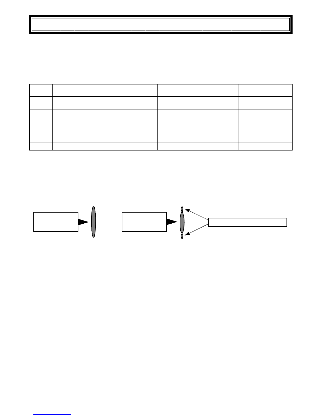
NOTE: In order to test if a tip is worn, spray a small amount of suitable material on a test surface and
observe the spray pattern produced on the surface. Try to obtain an even elliptical spray pattern by
first adjusting the pressure down, then gradually increasing pressure until full atomization is achieved.
This should result in a crisp spray pattern with sharp edges and even concentration, see diagram
below. If a satisfactory pattern is unattainable ( look for edges to be rounded with heavier
concentration ), then the tip is worn and should be replaced. Other causes of poor spray fan are
insu fficient spray pressure and material viscosity ( may requiring thinning ).
Good
Tip
Worn
Tip
Uneven S pray P atter n
NOTE: Use of excessively worn tip can result in apparent poor performance of pump.
ORIFICE SIZE
All tips are rated by the size of the orifice or bore size. The bore siz e is measur ed in thousandths of an inch
( .0 1 7 = 17 thousandths of an inch ). The size of tip required is b a sed on the consistency of the mater ial to
be sprayed. The thicker the paint , the larger the tip size required. Always consult the product label or ask
the paint retailer for the manufacturer's recommendations with regard to proper tip sizes.
FAN WIDTH
Fan wid th or pattern width is determined by the spray tip's "fan width" classification. This size is measured
in inches, and is determined whe n spraying 12 inches from the spray surface and the tip of the gun. Various methods of noting the fan widths are used by tip manufacturers. Ask your distributor for assistance.
NOTE: Two tips hav ing the same tip si ze, but different fan widths will deliver the same amount of paint
over a different area (wider or narrower strip).
SPRAY TIP REPLACEMENT
During use, especially with Latex paint, h igh pressure and material abrasion will cause the orifice to grow
larger. As the orifice grows larger, the fan width grows smaller. Repl ace tips before they become excessi vely worn. Worn tips waste paint, cause over spray, and decrease sprayer performance.
NOTE: When using Latex paint, a spray tip will wear at the rate of one size for approximately every 100
gallons o f material sprayed.
Owner’s Manual
Page 9
EC621 / E C725
 Loading...