

Page 1
Operation Manual
TX40 and CX40
Page 2

Product Features ................... page 4
Certification ....................... page 6
Installation, Operation & Maintenance .. page 8
Product Specifics ................... page 10
Troubleshooting .................... page 11
Introduction
Congratulations on purchasing one of the most
sophisticated hand torch available for hazardous areas.
page 2 Reference Operation Manual page 3
Reference Ex Torch and Charger
- designed for hazardous areas
The Reference solution offers an
unique solution combining multiple
tasks in order to reduce the need
for additional equipment, whether
the intended purpose is a hand
held solution, separate positioned
light source, or permanent installed
emergency equipment.
Improved Application
Induction technology eliminates
conductivity problems commonly
experienced with exposure to
saltwater, oil, mud, and extreme
weather conditions. This pattented
galvanic power transfer technology
furthermore enables the Reference
torch to be recharged within Zone
1 gas hazardous environments, and
operated under Zone 0 conditions.
Reduced Maintenance
Intelligent routines regularly perform
specific tests on both torch and charger
to monitor the system condition.
Charging routines are performed at
scheduled intervals to ensure optimal
battery capacity, and to maintain long
term durability.
Increased Safety
In the event of a power outage, the
torch will automatically turn on and
illuminate its location, making the
Reference solution an important asset
towards safety installations.
Page 3
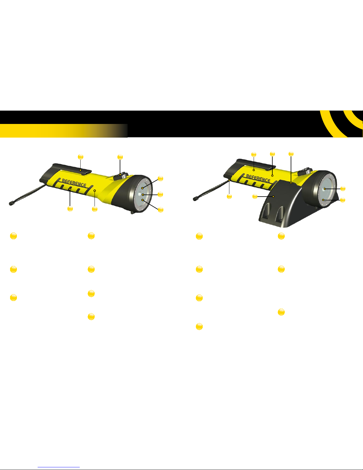
Innovative Belt Clip
– Improved belt clip functionality allows
torch to be independently placed upright
at various angles, leaving operator fully
capable of performing tasks with both
hands.
Operation Zone 0
– Certified for operation under Zone 0, 1,
and 2 conditions, removing any boundar y
limitations for utilization within a gas
hazardous environment.
3mm Hardened Glass
– 3mm hardened scratch resistant glass
protects optical components, maintaining
light intensity and beam conformity.
Permanent Maintenance Free Batter y
Solution
– With the sealed and self-maintained
rechargeable battery feature, general
maintenance cost is reduced while eliminating
the need for spare parts.
Low Voltage Shutdown
– A low voltage shutdown procedure is
automatically performed in the event of deep
discharge, preventing permanent damage to
internal batteries.
Seal Point For Emergency Use
– Optional safety feature allows torch and
charger to be sealed together with a securing
wire, enabling application towards emergency
lighting equipment.
Emergency Light Activation
– Embedded safety routine automatically
activates torch in the event of a power outage
to illuminate its location.
Product Features
Latest Led Technology Combined With
4° Lens
– 3rd generation LED and the embedded
4º lens optimize battery utilization while
producing a bright and uniform beam of light
on any targeted surface area.
Low Battery Indication
– The built in low batter y procedure reduces
light intensity to 30%, indicating the need for
recharge and ensuring efficient utilization.
Intelligent Battery Routines
– Scheduled charging routines and battery
monitoring are performed to ensure optimal
capacity and long term durability.
Textured Rubber For Extra Grip
– Main body shaft is covered with textured
rubber, ensuring a fir m and comfortable grip
under moist conditions such as rain, oil, mud
etc.
Torch And Charger Condition
Indicator
– Intelligent routines regularly perform
specific tests on both torch and charger to
monitor the systems condition and report
any irregularities.
Zone 1 Certified Weatherproof
Charging System
– Galvanic power transfer allows charging
without any metallic connection, enabling
torch to be recharged within Zone 1
conditions, while eliminating corrosion and
other conductivity issues due to water, oil,
mud etc.
Attach Point For Safety Wire
– Firm attach point for safety wire, giving
the option of securing the torch against
accidental free fall while mobile.
7
1
2 3
5
4
6
5
4
3
7
6
1
2
1
2
3
4
5
6
7
1
2
3
4
5
6
7
page 4 page 5Reference Operation Manual
Operation Maintenance & Safety
Page 4
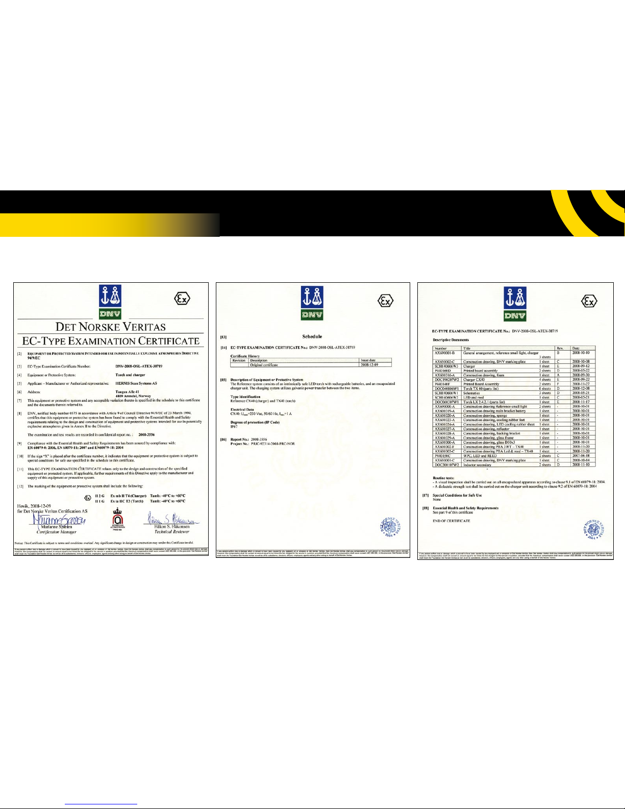
Certification
page 6 page 7Reference Operation Manual
Page 5
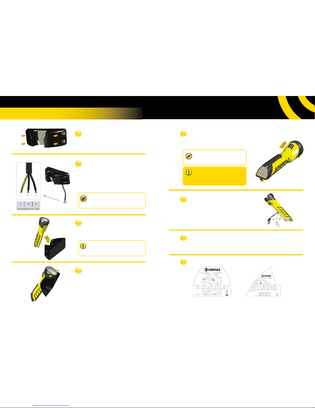
• Connect supplied cable to power source.
• Connect grounding cable where applicable.
• Termination of the power cord must be in an ATEX
certified junction box and as shown in illustration.
1
2
3
4
• Condition LED will start ashing green after
approximately 5 seconds when charging process has
been initialized.
• Continuous green LED indicates a fully recharged and
operational torch.
5
• Activate torch by moving switch knob
forward as shown in illustration.
6
Certification Tag
Sample: Torch TX40 Sample: Charger CX40
7
8
General Maintenance
Bracket Option
Torch Activation
Condition LED
Torch Insertion
Power Connection
Carger Mount
Installation, Operation & Maintenance
• Fasten charger with 4xM5 screws or
stud bolts using a torque of 1-2 Nm.
• Insert torch into charger as illustr ated. The at surface
of the torch must face towards the charger.
page 8 page 9
Note:
Avoid installation causing continuous exposure to direct
sunlight preventing visual inspection of condition LED.
Note:
Placing metal objects between torch and charger
surface may obstruct the charging process.
Note:
Due to the Reference torch illumination intensity,
direct exposure to eyes is not recommended.
Warning:
Do not open or disassemble torch within a gas
hazardous environment. Any disassembling of
Reference products will affect warranty.
• Place support bracket within the illustr ated
angles to enable fixed upright lighting.
• As required maintenance, inspect torch and charger regularly for physical damage. When
cleaning Reference products, wipe torch and charger with soap and a clean cloth.
Page 6
Product Specifics
Troubleshooting
No light produced when torch
is turned on
The torch may be completely discharged. Insert torch into
charger to initiate recharge process.
Torch automatically lights up
when inserted into charger
Charger may not receive current from its power source
which results in torch activating emergency mode. Check
power source, connectors, and cable for damage.
Green LED flashes when torch
is placed in charger
Flashing green light indicates that batteries are currently being
recharged. LED will stop ashing and turn continuous green
when batteries are fully recharged.
Red LED flashes when torched
is placed in charger
Flashing red light indicates that the torch does not receive
correct voltage from the charger. Check that the torch has
been correctly inserted into char ger, and that there is no
significant buildup of mud or dirt obstructing the char ging
process.
Red LED is activated when
torch is placed in charger
Continuous red light indicates an automatic maintenance test
has failed. Try reinserting torch into charger. Torch should be
replaced if problem persists.
In the event of any problems still present after closely reviewing the above table, or other
irregularities occuring during oper ation and handling, please contact Reference helpdesk for support.
P.O. Box 619, NO-4809 Arendal
Norway
Phone: +47 37 06 37 00
Email: [email protected]
www.reference.no
page 10 page 11Reference Operation Manual
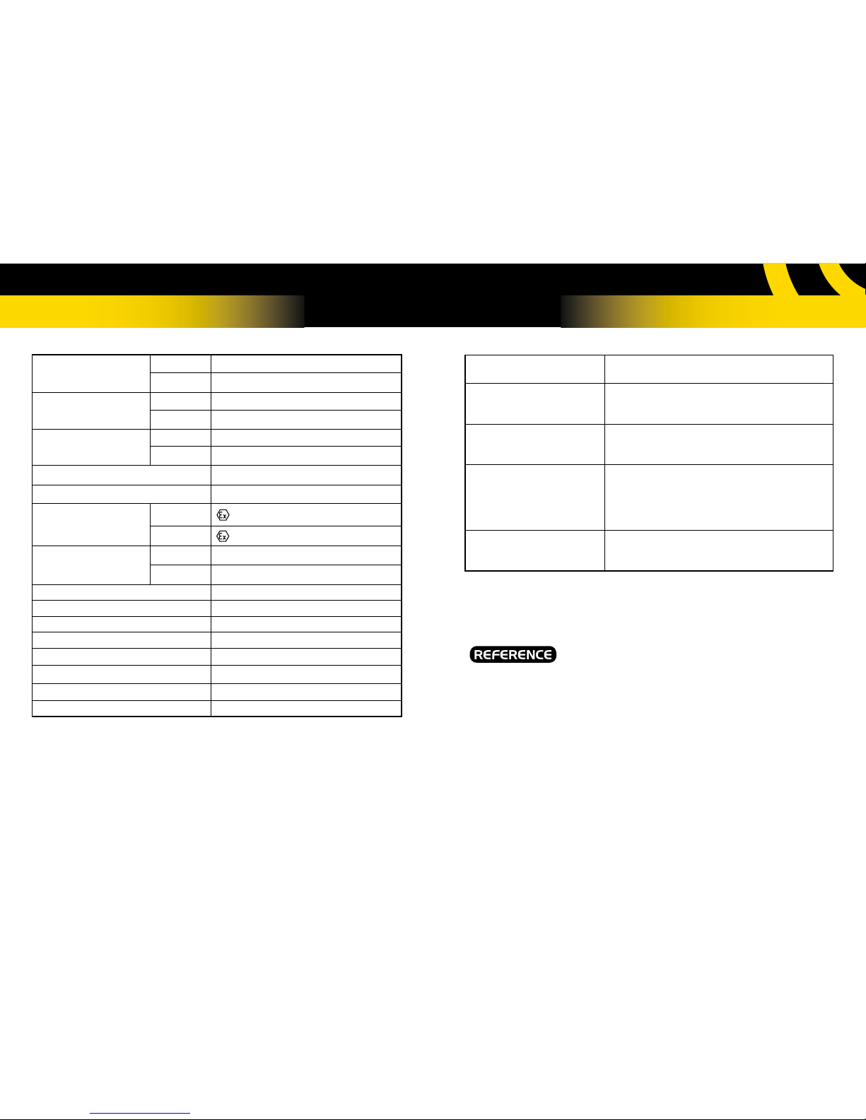
Model Name
Torch TX40
Charger CX40
Weight
Torch 600g
Charger 600g
Measurements
(mm)
Torch 230x70x70
Charger 185x65x60
Power Cable Lenght 2 m
Charger Input Voltage 100-250V
AC
50/60Hz 1.0A max
Certification Code
Torch II 1 G Ex ia IIC T3
Charger II 2 G Ex mb II T4
Area Classification
(gas)
Torch Zones 0, 1 & 2 - Gas groups IIA, IIB, IIC
Charger Zones 1 & 2 - Gas group II
Ambient Temperature -40/60ºC
Ingress Protection (Ip) 67
Light Type, Effect High efficiency LED, 3 watts
Lens Polycarbonate with 4° spread
Performance (1m) 200 lm
Operation Time Approx 5 hours
Recharge Time Approx 3 hours (80% in 2 hours)
Operating Life More than 1000 recharge cycles
Page 7
P.O. Box 619, NO-4809 Arendal
Norway
Phone: +47 37 06 37 00
Email: [email protected]
www.reference.no
 Loading...