

Page 1

HERMOS AG
LFM 4x Reader Rev1.3
Gartenstraße 19 • 95490 Mistelgau
Phone: +49 9279 991 - 0
E-mail: rfid@hermos.com
back to the table of contents
www.hermos.com
1
RFID
WE GENERATE SOLUTIONS
Englisch
Customer manual
LFM 4x Reader Rev1.4
Page 2

Customer manual
LFM 4x Reader
RFID
WE GENERATE SOLUTIONS
LFM 4x Reader Rev1.4
2
www.hermos.com
0. Table of contents
0. Table of contents .................................................................................................................................. 2
1 . I n t r o d u c t i o n ............................................................................................................................... 6
1.1 Using the device 7
2. Version history ...................................................................................................................................... 8
3. Used abbreviations and designations ................................................................................................... 8
4. General instructions .............................................................................................................................. 9
4.1 Objective of the product manual 9
4.2 Warranty and liability 9
5. Safety instructions and warnings ........................................................................................................ 10
5.1 Scope and symbols 10
5.2 Safety symbols - according to DIN 4844-2 10
5.2.1 Mandatory signs 11
5.2.2 Warning signs 11
5.2.3 Prohibition signs 11
5.2.4 Other signs 12
5.3 Obligations 12
5.3.1 Operator’s obligations 12
5.3.2 Responsibilities of operating personnel 13
5.3.3 ESD Instructions 13
5.4 Residual risks 14
5.5 Supplemental instructions 15
5.5.1 Regulations and certifications 15
6. Functional description ......................................................................................................................... 16
6.1 General information 16
6.2 Basic functions - operating modes 16
6.2.1 Normal operation 16
6.2.2 Polling mode 16
6.2.4 Test module 16
6.3.1 Top view 17
6.3.2 Front view 18
6.3.3 Back view 19
6.4 Technical Specification 20
6.4.1 Power supply and current input 20
6.4.2 Device labels 21
6.4.3 Device Label FCC ID 2AP5OLFM-4x 21
Feh
Page 3
Customer manual
LFM 4x Reader
RFID
WE GENERATE SOLUTIONS
LFM 4x Reader Rev1.4
3
www.hermos.com
ler! Textmarke nicht definiert.
6.4.4 Test mode sticker 22
7. Installation ........................................................................................................................................... 23
7.1 Safety instructions 23
7.2 Qualified installation personnel 24
7.3 Unpacking 24
7.4 Mounting the device 25
7.5 Installing the antenna 26
7.5.1 Positioning the antenna 26
7.5.2 Rod Antenna M dimensions 27
7.5.3 Connecting the antenna 27
7.6 Power Supply 27
7.7 DIP-switch 28
7.8 RS232 connection 29
8.Commissioning .................................................................................................................................... 30
8.1 Operating conditions 30
8.2 The serial interface parameters 30
8.3 Parameter of the ethernet interface 31
8.3.1 Change networksettings with DeviceDiscoverer 31
8.3.2 Firmware update with DeviceDiscoverer 33
8.3.3 Test Device with DeviceDiscoverer 34
9. Operating ............................................................................................................................................ 37
9.1 Operating personnel 37
9.2 Protocol change 37
9.2.1 General 37
9.2.2 Automatic protocol detection 37
9.3 Addressing the antenna port 38
9.4 Customer Factoryparametersets 39
10. ASCI-I1 Communication protocol ..................................................................................................... 40
10.1 Structure of the communication protocol 40
10.2 Packet content 40
Packet header 40
Message data 41
Packet end 41
10.3 Data elements 42
10.4 Protocol Commands 45
10.4.1 X - Read data 47
10.4.2 R – Automatic read 48
10.4.3 W - Write data 49
Page 4

Customer manual
LFM 4x Reader
RFID
WE GENERATE SOLUTIONS
LFM 4x Reader Rev1.4
4
www.hermos.com
10.4.4 G – Query parameter 50
10.4.5 F – Query parameter 51
10.4.6 P – Set parameter 52
10.4.7 N – Reset 53
10.4.8 e – Error message 54
10.4.9 E – Error message 54
10.4.10 H – Heartbeat 55
10.4.11 V – Query software version 56
10.4.12 L - Lock data area 57
10.4.13 I – Adjust RF module 58
10.4.14 J – RF module Queries the vote 59
10.4.15 A – Sensor event object removed 60
10.4.16 B – Sensor event object detected 61
10.4.17 O – Set output 62
10.4.18 Q – Querying the status of the inputs and outputs 63
10.5 Parameter 64
10.6 Message examples 67
10.7 Error Codes 69
10.8 Wiring of the outputs 71
10.8.1 ASC-W1 Mode: Reader in operation mode and sensor triggered reading 71
10.8.2 ASC-W1-Mode: Reader in operation mode and external triggered reading 73
10.9 ASCII – table 75
11.SECS / HSMS Communications protocol .......................................................................................... 78
11.1 Structure of a message 78
11.2 Directory Data Elements 81
11.3 Protocol commands 87
11.3.1 Stream 1 (system state) 88
11.3.2 Stream 2 (system control) 89
11.3.3 Stream 3 (Material-state) 91
11.3.4 Stream 5 (Exception handling) 93
11.3.5 Stream 9 (system error) 93
11.3.6 Stream 18 (control and data transfer) 95
11.4 Parameter 101
11.5 Examples of a SECS / HSMS message 109
11.6 Error codes 110
12. Service and Troubleshooting ................................................................................................... 111
12.1 General information 111
12.2 Troubleshooting personnel 111
Page 5

Customer manual
LFM 4x Reader
RFID
WE GENERATE SOLUTIONS
LFM 4x Reader Rev1.4
5
www.hermos.com
12.3 Safety instructions 112
12.4 Error indications on the device 113
12.5 No communication with the reading device 113
12.6 Software releases 114
12.7 Customer service 115
13. Disassembly and storage ........................................................................................................ 116
13.1 Disassembly 116
13.2 Storage 116
14. Transport and disposal ........................................................................................................ 116
14.1 Transport 116
14.2 Disposal 116
Page 6

Customer manual
LFM 4x Reader
RFID
WE GENERATE SOLUTIONS
LFM 4x Reader Rev1.4
6
www.hermos.com
1. Introduction
These operating instructions correspond with the "Radio and Telecommunications
Terminal.Equipment Act and Directive 2014/53/EU (RED) "
These operating instructions are intended for the operator who must pass these on to the personnel
responsible for installation, connection, use, and repairs of the machine.
The operator must ensure that the information contained in these operating instructions and in the
accompanying documents has been read and understood.
The operating instructions must be kept at a known place that is easy to reach, and they must be
consulted if there is the slightest doubt.
The manufacturer assumes no responsibility for damage to persons, animals, or objects or to the
unit itself arising from the improper use or the disregard or insufficient consideration to the safety
criteria contained in these operating instructions or based on modifications of the unit or the use of
unsuitable replacement parts.
The copyright for the operating instructions lies solely with
HERMOS AG
Track & Trace - RFID Division Gartenstr. 19
95490 Mistelgau
or its legal successor.
Reproduction or circulation of this document to third parties only by express written permission of
copyright holder. This also applies if only excerpts of the document are copied or circulated.
These same conditions apply to the disclosure of the document in digital format.
As of: July - 2018
Page 7
Customer manual
LFM 4x Reader
RFID
WE GENERATE SOLUTIONS
LFM 4x Reader Rev1.4
7
www.hermos.com
1.1 Using the device
The device is exclusively used to read and write passive LF transponders.
Any other use of the machine or any use beyond its intended purpose is considered non-intended
and thus improper.
In this case, the device safety and the device protection provided may be compromised. HERMOS
AG is not liable for damages resulting from such use.
The device was developed for the use in an industrial environment as a built-in device in other
systems. It was not developed as a stand-alone or mobile device in a non-industrial environment,
such as dome- stic, vehicle or open air use.
Intended use also includes the following:
• Following all the operating instructions
• Following all the safety instructions
Improper use, which can endanger the unit, the user and third parties, include:
• The use of the device contrary to its intended use
• Changes to the device as well as attachments and conversions
• Operating the unit when there are obvious problems
WARNING
Danger of injury due to unauthorised modifications
There are risks from unauthorised modifications on the device.
Only original spare parts from the manufacturer must be used. No
modification, attachment or conversion may be performed on the device
WARNING
without the permission of HERMOS AG.
Danger of injury and interruption of operation due to improper use
There are risks through the improper use of the device.
The device must only be used according to its intended use.
Page 8
Customer manual
LFM 4x Reader
RFID
WE GENERATE SOLUTIONS
LFM 4x Reader Rev1.4
8
www.hermos.com
Version
Date
Author
Amendments
1.0
12.05.2017
HERMOS AG, MZ
Initial version of customer documentation
1.1
10.07.2017
HERMOS AG, RK
Document revised and added parameters
1.2
19.01.2018
HERMOS AG, RK
ASC-W1 mode documented
1.3
09.07.2018
HERMOS AG, RK
Factoryparametersets 4 and 5
documented
1.4
26.02.2019
HERMOS AG, RK
Chapter 9.3 and Reader-ID revised
Chapter 9.4 Factoryparametersets revised
Chapter 10.5 und 11.4 Changes of
parameters
Chapter 12.6 added softwarerevision V1.5
Chapter 8.3 revised
RFID
Radio Frequency Identification
LF
Low Frequency 134,2 kHz
SEMI
Semiconductor Equipment and Materials
SECS
SEMI Equipment Communications Standard
HSMS
High-Speed SECS Message Service
PoE
Power over Ethernet
DHCP
Dynamic Host Configuration Protocol
2. Version history
3. Used abbreviations and designations
Page 9

Customer manual
LFM 4x Reader
RFID
WE GENERATE SOLUTIONS
LFM 4x Reader Rev1.4
9
www.hermos.com
4. General instructions
All previous versions of this document lose their validity with the issue of this version.
We compiled the information in this document according to the best of our ability.
HERMOS AG does not guarantee the accuracy and completeness of the information
provided in this document and is also not liable for consequential damages based on
faulty or incomplete information.
4.1 Objective of the product manual
The product manual serves as support and contains all the necessary information
that must be followed for general safety, transport, installation and operation.
The product manual with all safety instructions (as well as all additional documents) must be:
• Followed, read and understood by all persons working with the unit (especially
knowledge of the safety instructions)
• Easily available at all times to all persons
• Consulted if even the slightest doubt arises (safety)
Objectives:
• Prevent accidents
• Increase the service life and reliability of the unit
• Reduce the costs of production downtime
4.2 Warranty and liability
The „General Terms and Conditions of Sale and Delivery“ of HERMOS AG shall apply.
The warranty period is 24 months beginning with the delivery of the device, which is
verified by the invoice or other documents.
The warranty includes repairs of all damages to the unit that occur during the warranty
period, and were clearly caused by material or manufacturing defects.
Warranty and liability claims in the event of personal injury or property damage are
excluded if they arise from one or more of the following causes:
• Improper use of the unit
• Disregarding the information in the operating instructions
• Unauthorised structural modifications of the unit
• Insufficient maintenance and repairs
• Disaster events due to impact with foreign objects or force majeure
Page 10
Customer manual
LFM 4x Reader
RFID
WE GENERATE SOLUTIONS
LFM 4x Reader Rev1.4
10
www.hermos.com
5. Safety instructions and warnings
5.1 Scope and symbols
Follow the general safety instructions as well as special safety instructions included
in the chapters.
The unit was built according to state-of-the-art technology and recognised safety regulations. In
order to prevent danger to life and limb of the user, third parties, or the unit, only use the unit for its
intended purpose and in perfect condition with regard to safety.
Bodily injuries and/or property damages resulting from non-compliance with the
instructions pro- vided in the operating instructions are the responsibility of the
company operating the unit or the assigned personnel.
Faults that may compromise safety must be eliminated immediately.
DANGER
Risk of death, injury and property damage.
There is a risk of danger due to disregard of the product manual and
the safety information contained therein.
Read the product manual carefully before putting the unit into
operation for the first time. Fulfil all required safety conditions.
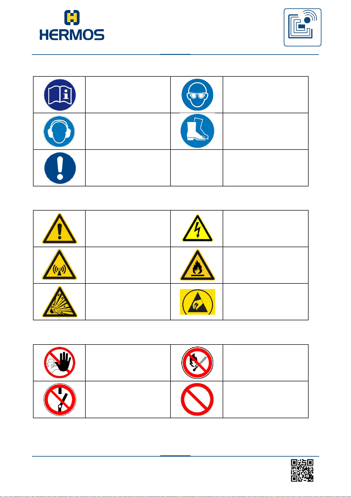
5.2 Safety symbols - according to DIN 4844-2
The following special safety symbols in accordance with DIN 4844-2 are used at the
corresponding passages in the text of this product manual and require special attention
depending on the combi- nation of the signal word and symbol.
DANGER
Risk of injury due to disregarding the safety symbols.
Risks exist when disregarding warnings in the
operating instructions. Follow all warnings.
Page 11
Customer manual
LFM 4x Reader
RFID
WE GENERATE SOLUTIONS
LFM 4x Reader Rev1.4
11
www.hermos.com
Observe additional
information
Use safety goggles
Wear ear protection
Wear safety shoes
Important note
Warning of a hazardous
area
Warning of hazardous
electrical voltage
Warning of electromagnetic
radiation
Warning of flammable
substances
Warning of explosive
substances
Warning of electrostatically
sensitive components
Unauthorised access is
prohibited
Fire, open flame and
smoking prohibited
Switching prohibited
Prohibited
5.2.1 Mandatory signs
5.2.2 Warning signs
5.2.3 Prohibition signs
Page 12
Customer manual
LFM 4x Reader
RFID
WE GENERATE SOLUTIONS
LFM 4x Reader Rev1.4
12
www.hermos.com
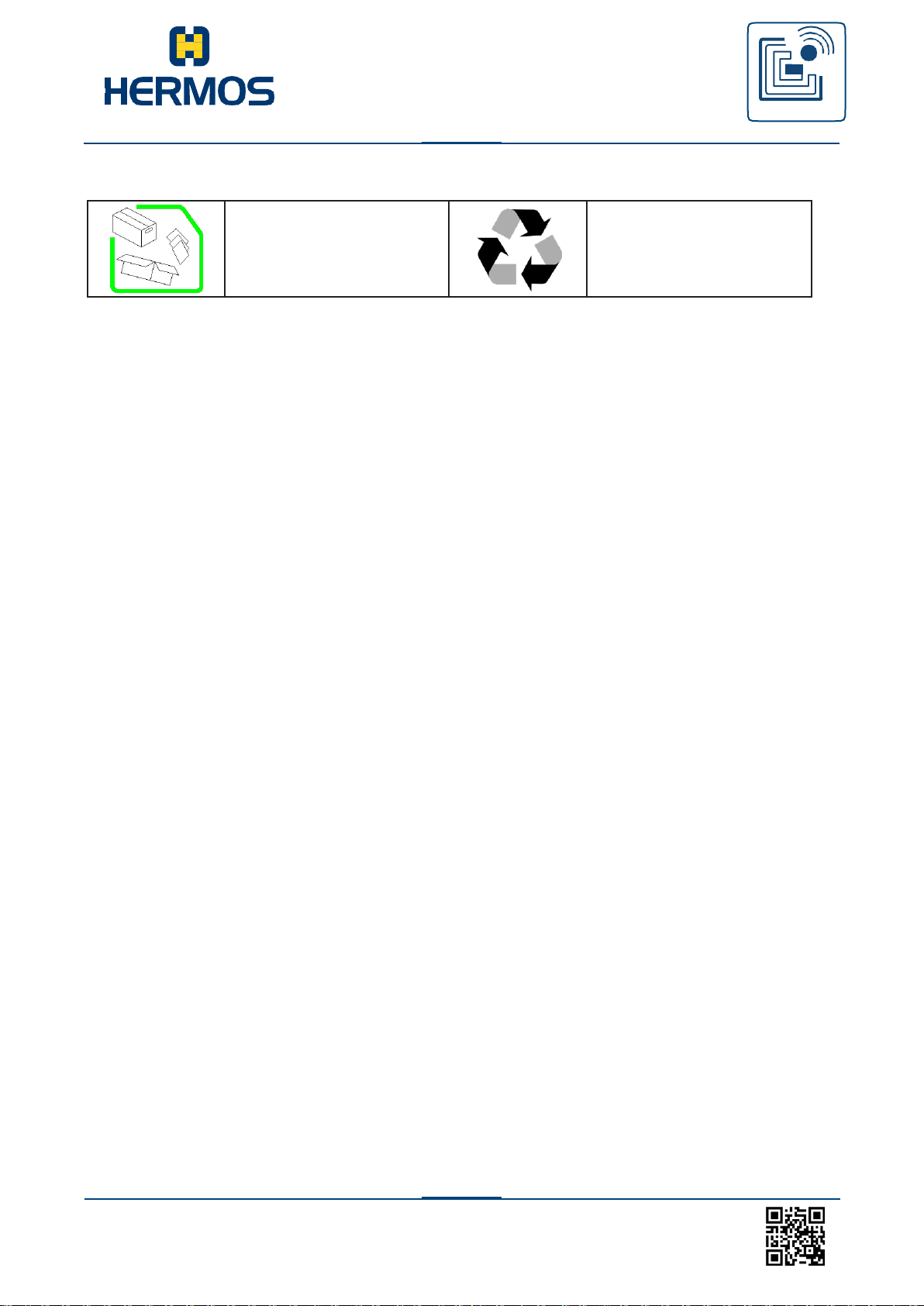
Verpackungsmaterial vorschriftsgemäß entsorgen
Recycling
5.2.4 Other signs
5.3 Obligations
5.3.1 Operator’s obligations
A safe condition and use of the unit is a requirement for a safe operation of the unit. For that reason, the operator has the obligation to ensure that the following points are adhered to:
The unit may only be operated by trained and authorised personnel.
Prohibit unsafe or dangerous working methods! If necessary, check the conduct
and actions of its personnel!
Have personnel who must be trained, instructed or within the scope of general
training work only on the unit under the supervision of an experienced person!
Have the personnel confirm by their signature that the operating instructions have
been understood!
Precisely establish responsibilities according to the various task
areas (operation, installation)!
Operating personnel must be required to immediately report any occurring and
identifiable safety deficiencies to their superior!
Page 13
Customer manual
LFM 4x Reader
RFID
WE GENERATE SOLUTIONS
LFM 4x Reader Rev1.4
13
www.hermos.com
5.3.2 Responsibilities of operating personnel
The operating personnel are obligated to contribute to the prevention of work accidents and their
consequences by their personal conduct.
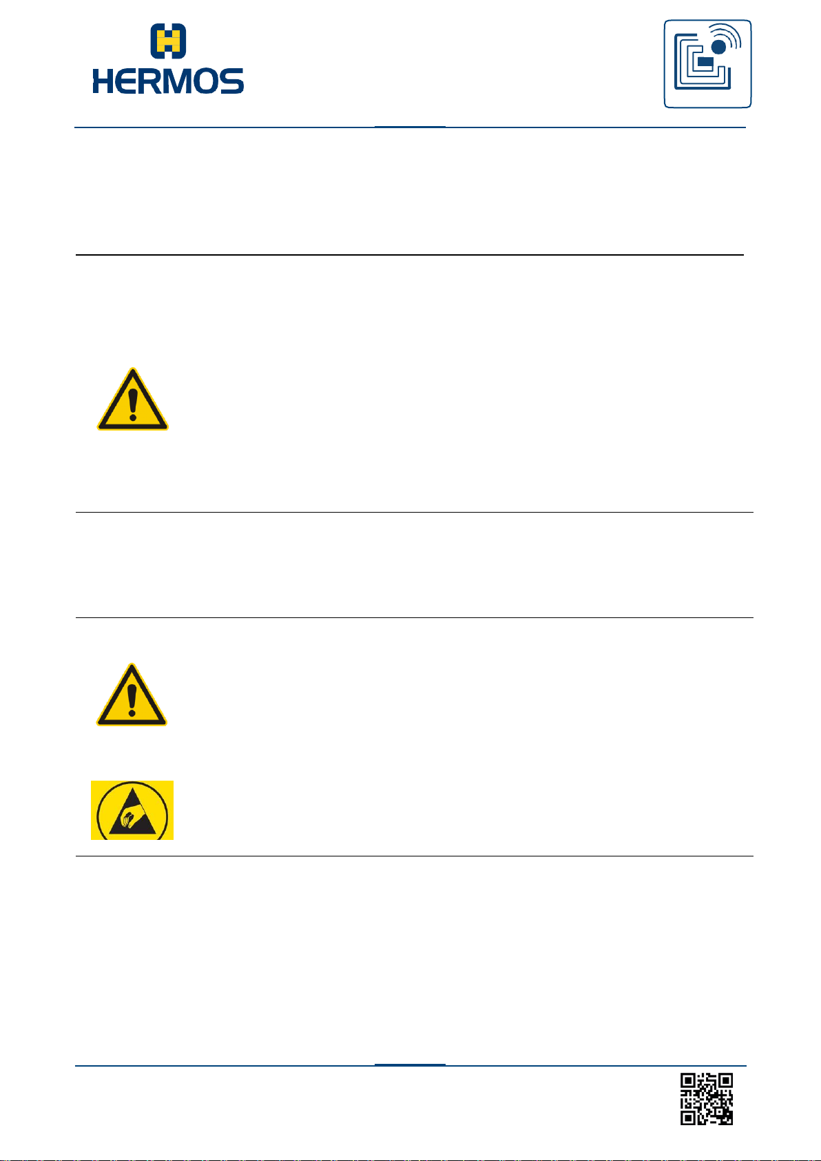
WARNING
5.3.3 ESD Instructions
CAUTION
Risk of injury due to insufficient personnel qualifications
There are dangers to personnel and the proper operation due to
inadequately qua- lified personnel.
Only trained personnel may operate the unit.
New operating personnel must be instructed by the existing operating
personnel. The operator must precisely regulate the personnel’s areas
of responsibility, com- petence, and monitoring precisely.
The personnel for the areas of responsibility mentioned above must
have the corresponding qualification for this work (training, instruction).
If necessary, this can be done by the manufacturer on behalf of the
operator. In case of disregard, all warranty claims are void.
Static electricity can damage electronic components in the unit. All
persons who install or maintain the unit must be trained in ESD
protection.
Disconnect the power supply prior to removing or adding components!
Observe the basic principles of ESD protection
Take the appropriate ESD precautionary measures
ESD protective measures must be applied when opening the unit.
Page 14
Customer manual
LFM 4x Reader
RFID
WE GENERATE SOLUTIONS
LFM 4x Reader Rev1.4
14
www.hermos.com
5.4 Residual risks
Despite all precautionary measures taken, there may still be residual risks that are not apparent.
Adhering to the safety instructions, the intended use, and the product manual as a whole can re- duce
residual risks.
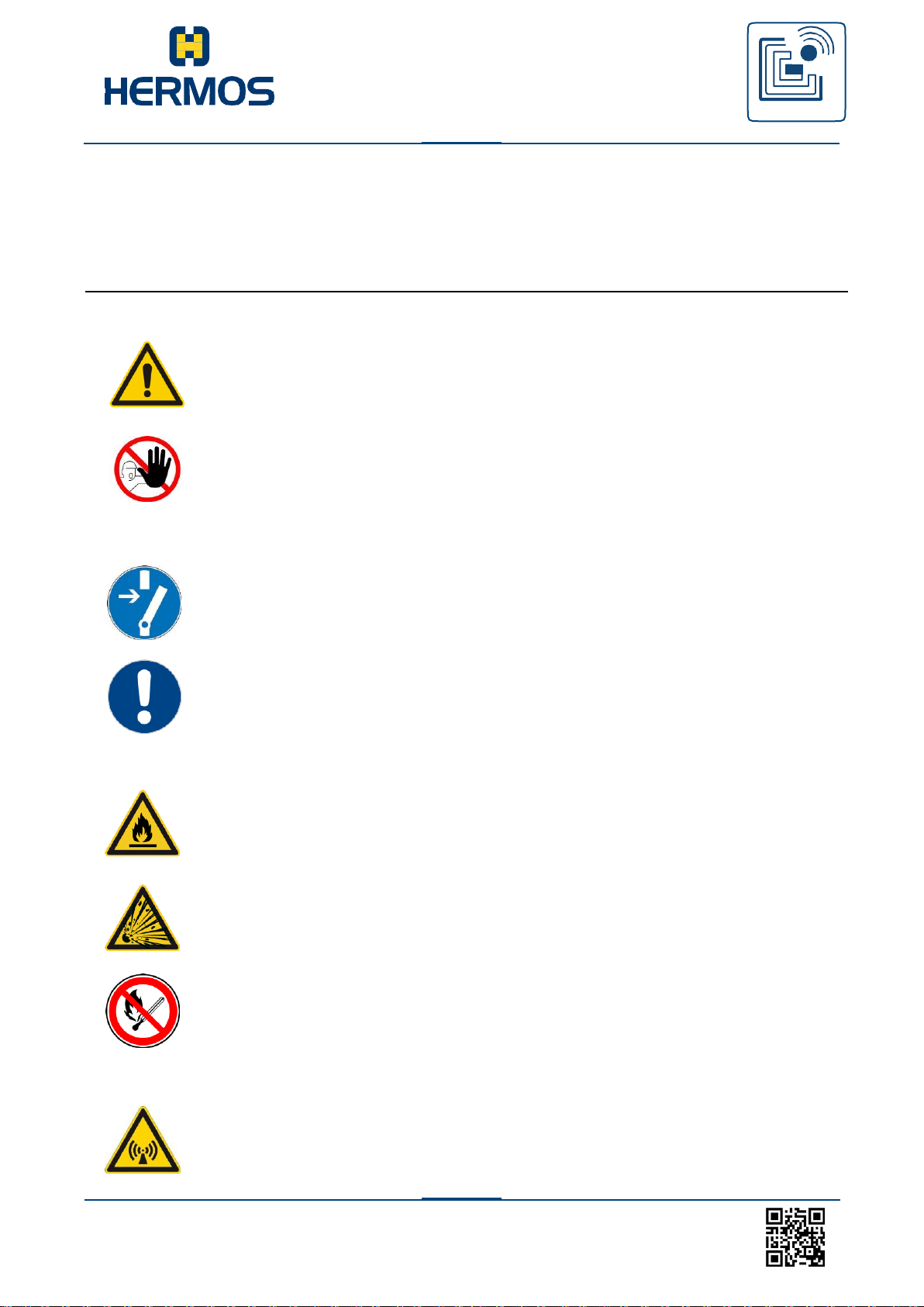
DANGER
Danger caused by electrical current
Electrical residual energy remains in lines, equipment and devices after
shutting down the device.
Only qualified electricians may perform work on the electrical supply system.
ATTENTION
DANGER
WARNING
Disconnect the unit from the power supply system if active parts of the unit
can be accessed using tools. Access is only permitted by authorised
personnel.
Regularly check the electrical equipment of the unit. Regularly check all
moving cables for damage within the scope of maintenance and repair work.
Dangers of fire and explosion
There is a risk of fire and explosions in the vicinity of the device.
Smoking, exposed flames and fire are strictly prohibited in the vicinity of the unit.
Do not store any flammable liquids within the hazardous area of the device.
A fire extinguisher must be kept in the vicinity of the device.
Warning of electromagnetic radiation
Electromagnetic radiation develops when transmitting and receiving data. Arrange
the antenna in such a position that it is not in the vicinity or make
contact with the human body while transmitting.
The device satisfies the standard EN50364:2010 (Human Exposure).
Page 15

Customer manual
LFM 4x Reader
RFID
WE GENERATE SOLUTIONS
LFM 4x Reader Rev1.4
15
www.hermos.com
5.5 Supplemental instructions
Read and understand all safety and operating instructions prior to installing and operating
the device.
This documentation was written for specifically trained personnel. The installation,
operation and error handling may only be carried out by specifically trained personnel.
Keep these instructions. Keep this documentation in a location that is accessible to all
personnel involved with the installation, use, and error handling of the device.
Follow all warnings. Follow all warnings on and in the device and in the documentation.
Install the unit only in accordance with the manufacturer‘s instructions.
Use only the accessories and cables from the manufacturer.
Troubleshooting that is not described in the chapter a service and troubleshooting may
only be performed by the manufacturer.
When connecting cable connections, only pull on the plug and not on the cable.
Only use spare parts specified by the manufacturer.
The provisions of the accident-prevention regulations of the government safety organisations
always apply to all work on the unit.
Applicable, legally binding accident prevention regulations.
Applicable binding regulations at the place of use
Technical standards for safety and professional work
Existing environmental protection regulations
Other applicable regulations
5.5.1 Regulations and certifications
The electrical design and documentation satisfy the DIN / VDE, EN / IEC regulations.
Page 16

Customer manual
LFM 4x Reader
RFID
WE GENERATE SOLUTIONS
LFM 4x Reader Rev1.4
16
www.hermos.com
6. Functional description
6.1 General information
LF reading devices are radio frequency identification systems that use radio transmission to read
or write data of LF transponders (134,2 kHz), which operate as tamper-proof electronic tags. The
LF reading devices communicate with common transponders (134,2kHz) according to ISO 18000-2
and ISO 11785 that are available on the market.
The data is transmitted via the existing interface with the preset transmission parameters. If several interfaces are available and connected to the host, the transmission is always carried out on the
most recently used interface. The data is embedded in a defined communication protocol and
exchanged between the reader and host.
6.2 Basic functions - operating modes
During normal operation, the LF reading device supports various basic functions:
• Heartbeat function, software version query
• Scanning of transponders in the antenna area (UID)
• Reading data
• Writing data
• Locking data
• Setting and reading out parameters
• Setting and querying inputs and outputs
The LF devices can be set in 3 other operating modes by setting the parameters: Polling operation
(optional), sensor-triggered automatic reading and test mode.
6.2.1 Normal operation
During normal operation, the LF reading device is immediately ready for operation after a reset. It
does not perform any automatic actions in this mode (standby). During normal operation, actions are
triggered by protocol commands from the host.
A scanning procedure or reading in the data area is initiated by a command of the host system
using the communication protocol.¬
In addition to the actions triggered by the host, a corresponding message can be automatically sent
to the host and an automatic reading operation can be started by activating or releasing a sensor.
When the reading operation is successful, the read data is immediately transmitted to the host. If
several antenna ports are occupied simultaneously, the reading operations are processed sequentially.
Writing actions (data saved to a transponder) are generally only possible via commands from the
host.
6.2.2 Polling mode
LF reading devices can be set into a continuous reading state, which is referred to as
polling mode. The device then performs reading operations at regular intervals and
outputs the corresponding data of the read LF transponder.
The reading device also continues carrying out protocol messages in polling mode. This
may, however, result in delays in the poll rhythm. The polling functionality is optional
customer-specific available!
6.2.4 Test module
Page 17
Customer manual
LFM 4x Reader
RFID
WE GENERATE SOLUTIONS
LFM 4x Reader Rev1.4
17
www.hermos.com
www.hermos.com
The HERMOS LF reading devices support a test mode that facilitates setting up the antenna and
checking the reading ranges during commissioning. HF reading devices feature several DIP switches on the housing. These switches can be used to activate test mode.
The functions in test mode are described on a sticker located on the reading device housing. The
evaluation of the DIP switch depends on parameters
If the device is in test mode, the red status LED flashes at about 1 Hz. The yellow status LED then
indicates the status of the test mode. If the read or write process was unsuccessful, the yellow LED
flashes at the read or write frequency. If the read or write process is successful, the yellow LED
remains permanently lit.
With the existing I / O module, HERMOS LF readers with ASC-W1 protocol also show the successful or incorrect reading of the transponder at the respective first output port. See also behavior of
the output ports in test mode.
see also chapter „DIP-switch“
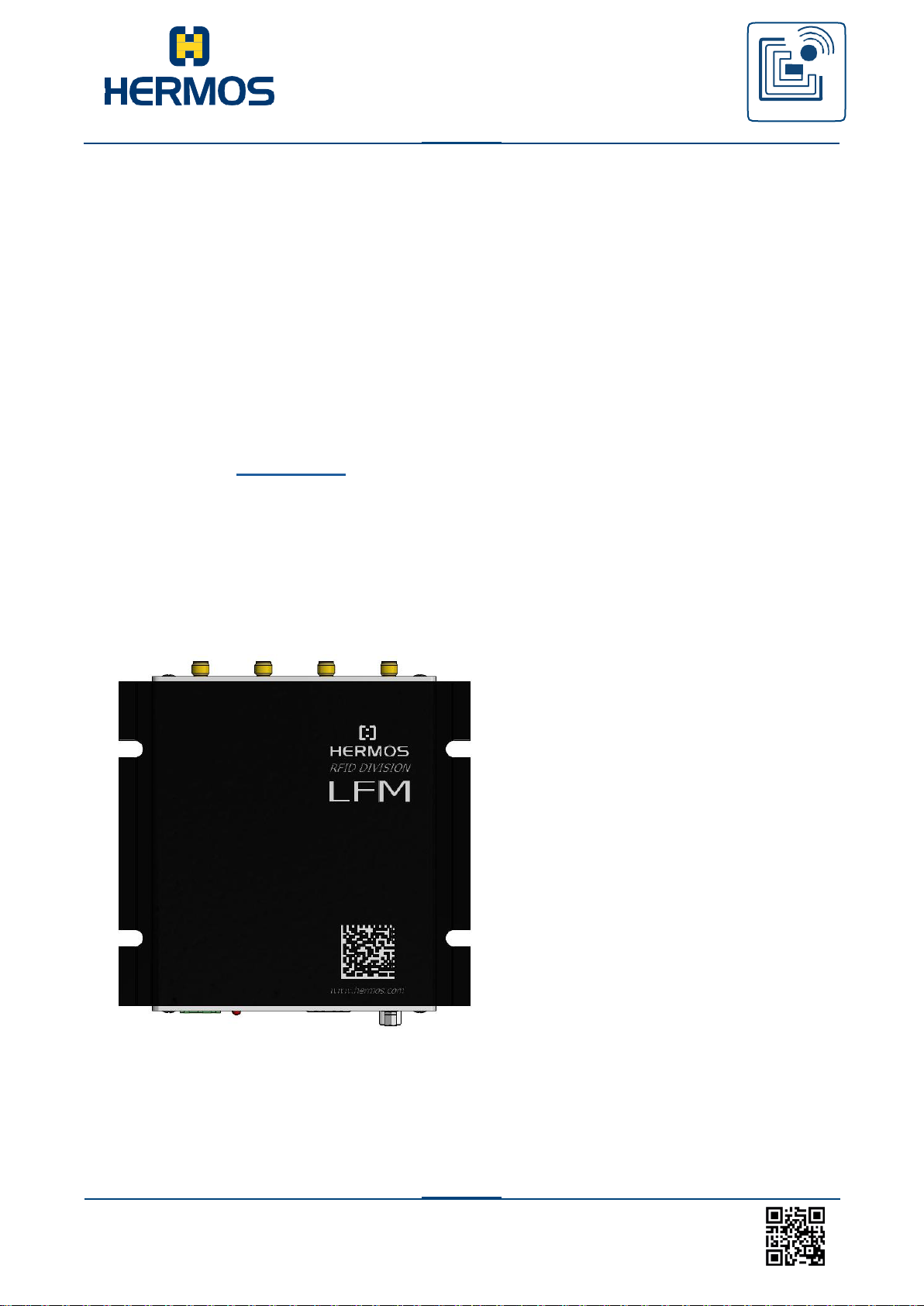
6.3 Illustration
6.3.1 Top view
1. Black and white anodised aluminium
housing
2. Reading device type imprint
3. Data Matrix Code
Page 18
Customer manual
LFM 4x Reader
RFID
WE GENERATE SOLUTIONS
LFM 4x Reader Rev1.4
18
www.hermos.com
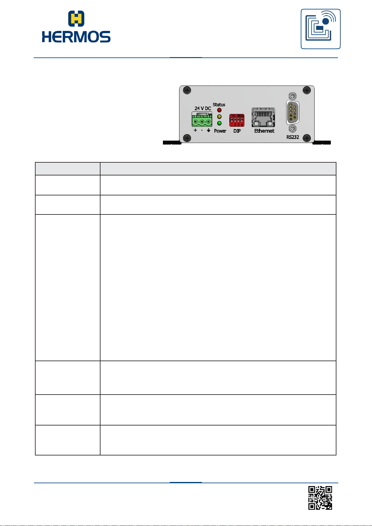
Component
Description
Power supply
connection
Three-pin socket for the connection of the 24V DC power supply.
Power-LED
The power LED indicates that the operating voltage is present and
the rea- ding device is ready for operation.
Status-LEDs
The two status LEDs are used for the reading and writing feedback in
test and polling mode. If the device is in test mode, the red status
LED flashes at about 1 Hz. The yellow status LED then indicates the
status of the test mode. If the read or write process was
unsuccessful, the yellow LED flas- hes at the read or write frequency.
If the read or write process is successful, the yellow LED remains
permanently lit.
In normal operation, if an error occurs, the display of this
occurs via the red LED:
Red LED constantly on: read error (no tag)
red LED flashing rapidly: antenna error (tuning, cable
break). This display will reset automatically with the next
valid reading.
After a restart, a short self-test of the LEDs, then display of the
protocol: SECS: The red LED goes on briefly
ASCII: The yellow LED goes on briefly
DIP-switch
DIP-switch 4 starts an automatic antenna
tuning. DIP-switch 3 activates a test
mode.
DIP-switch 1 and 2 serve the antenna selection.
Ethernet interface
The reading device features an Ethernet interface depending on the
de- vice model. The communication with the device can be carried
out via the 10/100 BaseT interface.
RS232 interface
Depending on the device model, the reading device features a RS232
in- terface. The communication with the device can be carried out via
the serial interface (9-pin Sub D)
6.3.2 Front view
1. Power supply connection
2. Status- and power LEDs
3. DIP-switch
4. Ethernet interface
5. RS232 interface
Page 19
Customer manual
LFM 4x Reader
RFID
WE GENERATE SOLUTIONS
LFM 4x Reader Rev1.4
19
www.hermos.com
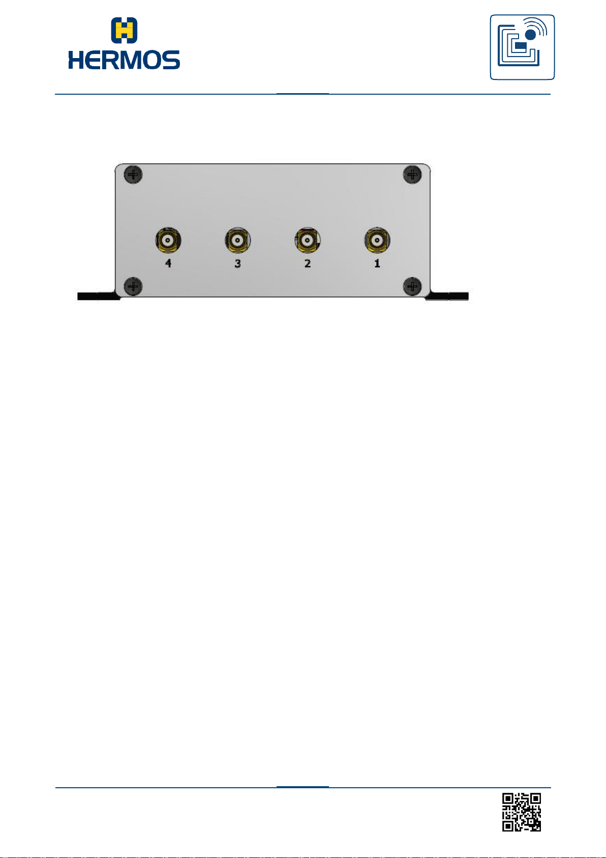
6.3.3 Back view
Page 20
Customer manual
LFM 4x Reader
RFID
WE GENERATE SOLUTIONS
LFM 4x Reader Rev1.4
20
www.hermos.com
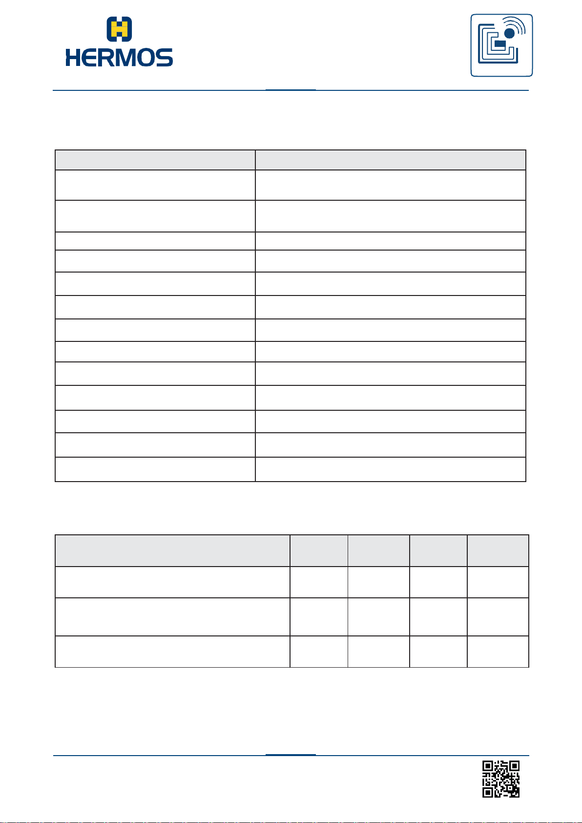
Technical data
Voltage (protected against reverse
polarity)
20 – 28 V DC,
Power consumption
(passive, reading, pulse-by-pulse)
75mA@24V, 200mA, max.400mA
Fuse type Nano2
375 mA
Operating temperature
-0 to 50 °C
Storage temperature
-20 °C to 70 °C
Permissible humidity at 50°C
25 – 80 %
Transmission frequency
134,2 kHz
Ethernet interface
10/100 BaseT,
Protocol
ASCII, SECS / HSMS
Housing material
Aluminium, black and white anodised
Protection
IP40
Reader dimensions
130 x 124 x 45 mm
Weight
approx. 500 g
Description
Min.
Typ
Max.
Unit
Voltage (reverse polarity protected)
20
24
28
V (DC)
Current consumption (Read/Write
Pulse manner (50ms)
110
330
mA
Current (passive)
80 mA
6.4 Technical Specification
6.4.1 Power supply and current input
Page 21
Customer manual
LFM 4x Reader
RFID
WE GENERATE SOLUTIONS
LFM 4x Reader Rev1.4
21
www.hermos.com
LFM Reader 4x
P/N: HRF.R.LFM.4x.Xx.xx.xxx
S/N: 1704HAG00123
P/O: HKxxxxxx
MAC: D8:80:39:xx:xx:xx
HERMOS AG
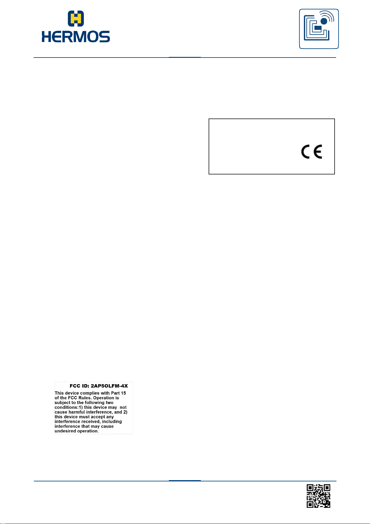
6.4.2 Device labels
The device label is located on the reading unit housing.
It contains a CE mark, article/serial number and the MAC address.
1. Designation
2. Article number (variants)
3. Serial number (example)
4. MAC address
5. Manufacturer
6.4.3 Device Label FCC ID 2AP5OLFM-4X
FCC
- The Federal Communications Commission (FCC) warns the users that changes or
modifications to the unit not expressly approved by the party responsible for compliance
could void the user's authority to operate the equipment.
RF exposure statement (mobile and fixed devices)
This device complies with the RF exposure requirements for mobile and fixed devices. However, the
device shall be used in such a manner that the potential for human contact during normal
operation is minimized.
- FCC §15.105 (a):
NOTE: This equipment has been tested and found to comply with the limits for a Class A digital
device, pursuant to part 15 of the FCC Rules. These limits are designed to provide reasonable
protection against harmful interference when the equipment is operated in a commercial
environment. This equipment generates, uses, and can radiate radio frequency energy and, if not
installed and used in accordance with the instruction manual, may cause harmful interference to
radio communications. Operation of this equipment in a residential area is likely to cause harmful
interference in which case the user will be required to correct the interference at his own expense.
Page 22
Customer manual
LFM 4x Reader
RFID
WE GENERATE SOLUTIONS
LFM 4x Reader Rev1.4
22
www.hermos.com
3 off: Start Antenna Tuning
3 on: Off-Read / On-Write
Testmode on/off
2 3 4
off on on
on off on
1
2
3
4
DIP Switches
DIP /Ant Port: 1
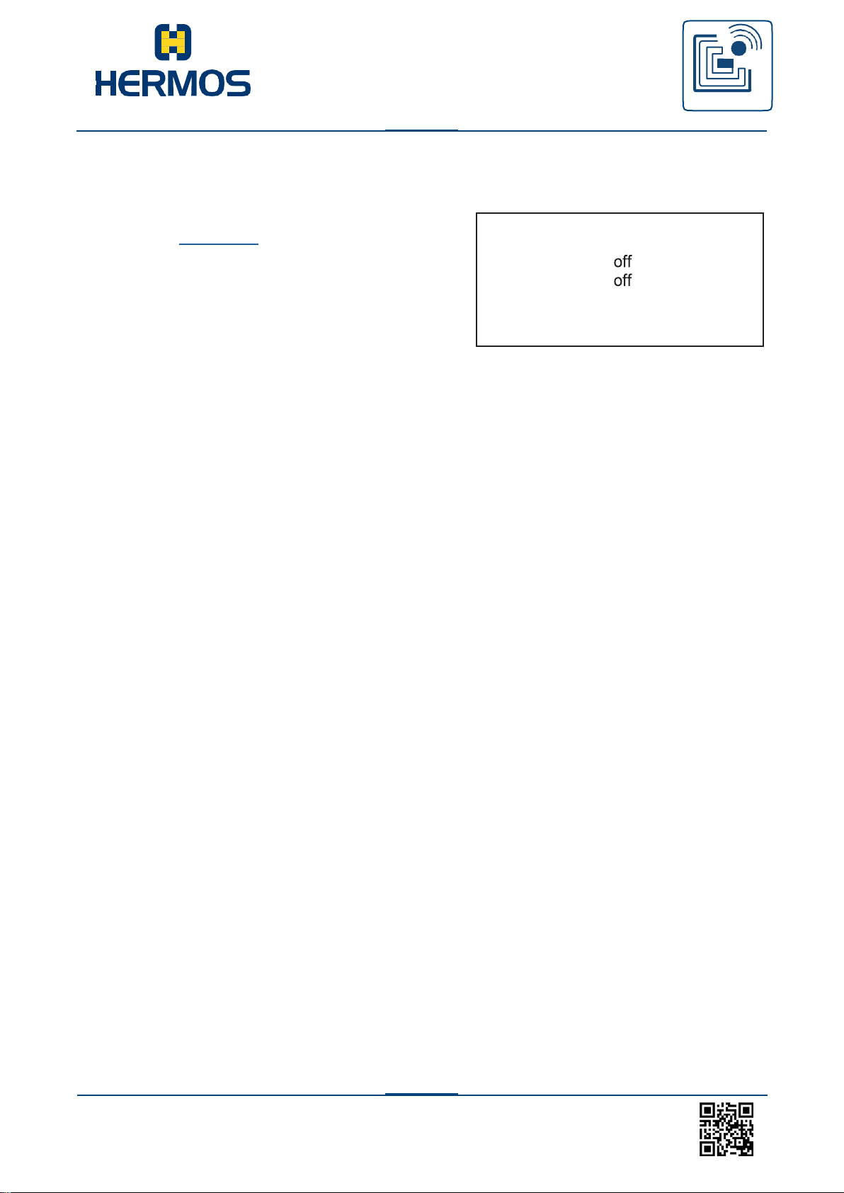
6.4.4 Test mode sticker
The device label is located on the reading unit housing.
By setting the DIP-switch 3 the test mode is activated.
The test mode read or write is set with the DIP switch 4.
The selection oft he antenna port is changed by the DIP
switched 1 and 2.
Further functions see section DIP switch.
Page 23
Customer manual
LFM 4x Reader
RFID
WE GENERATE SOLUTIONS
LFM 4x Reader Rev1.4
23
www.hermos.com
The unit is exclusively designed for indoor use in an industrial
environment. The unit may only be installed indoors with a temperature
and humidity level with in the range of the specified technical module
parameters.
Never use the unit near or in water.
Never pour liquids of any type over the unit. However, if the unit
should still come in contact with liquid, disconnect it and have it
checked by a technician.
Do not install the device near heat sources such as radiators, heat
regis- ters, stoves or other devices (including amplifiers) that
generate heat.
Do not install the unit in a flammable environment.
Never expose the device to extreme temperature fluctuations,
since con- densation otherwise develops inside the unit and
causes damages.
Do not install the device in the vicinity of voltage lines or other power
lines with which they could collide (for example, drilling), which could
result in serious injuries or even death.
The device (especially the antenna) should not be installed in the
immediate vicinity of electrical equipment such as medical
devices, monitors, telephones, TV sets and magnetic disks, and
metal objects.
This could result in reduced read and write ranges.
Never use the unit in explosive areas (such as paint warehouses).
Do not use the device in areas where it is exposed to vibrations or
shocks.
The installation location must be adequately illuminated during the
installation.
Never install the unit during a lightning storm.
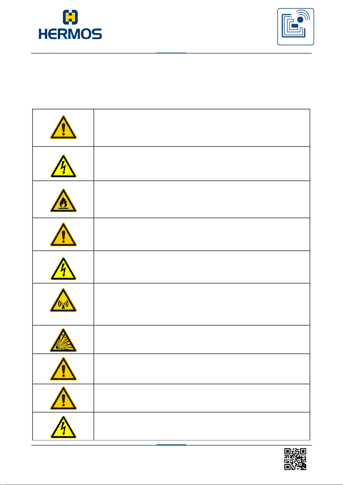
7. Installation
Follow the basic safety instructions in the chapter Safety instructions.
7.1 Safety instructions
Page 24
Customer manual
LFM 4x Reader
RFID
WE GENERATE SOLUTIONS
LFM 4x Reader Rev1.4
24
www.hermos.com
Make sure that the installation meets the requirements of the FCC
(country specific) for human exposure to radio frequencies.
The unit must only be installed by specially trained personnel. If you
have any doubts about the qualifications, please contact the
manufacturer.
If the unit is operated by untrained personnel, the reading
device and or connected devices may be damaged.
The packaging material consists of cardboard and foil.
Dispose of these materials separately under the respective
regulations of your country.
7.2 Qualified installation personnel
7.3 Unpacking
The LF reading device and the accessories can be packed customer-dependent in clean room
conditions. In order to maintain this condition, the devices must be unpacked in clean room conditions.
Page 25
Customer manual
LFM 4x Reader
RFID
WE GENERATE SOLUTIONS
LFM 4x Reader Rev1.4
25
www.hermos.com
The mounting surface must be stable, non-flammable, dry and
clean. If necessary, clean it before you install the device.
Only use components, cable and mounting materials provided by
HERMOS.
Only mount the components at the designated locations and make
sure that the operating and ambient conditions specified in the
technical data are always maintained.
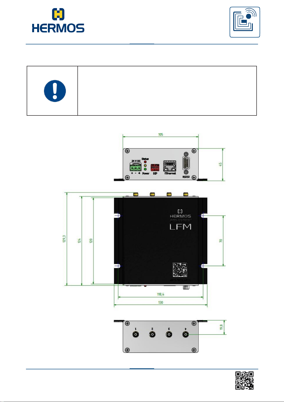
7.4 Mounting the device
Dimensions
Page 26
Customer manual
LFM 4x Reader
RFID
WE GENERATE SOLUTIONS
LFM 4x Reader Rev1.4
26
www.hermos.com
When installing the antenna, observe the required reading and
writing ranges. The reading device can only be used properly
if the transponder is located within the reading and writing range of the
antenna.
7.5 Installing the antenna
7.5.1 Positioning the antenna
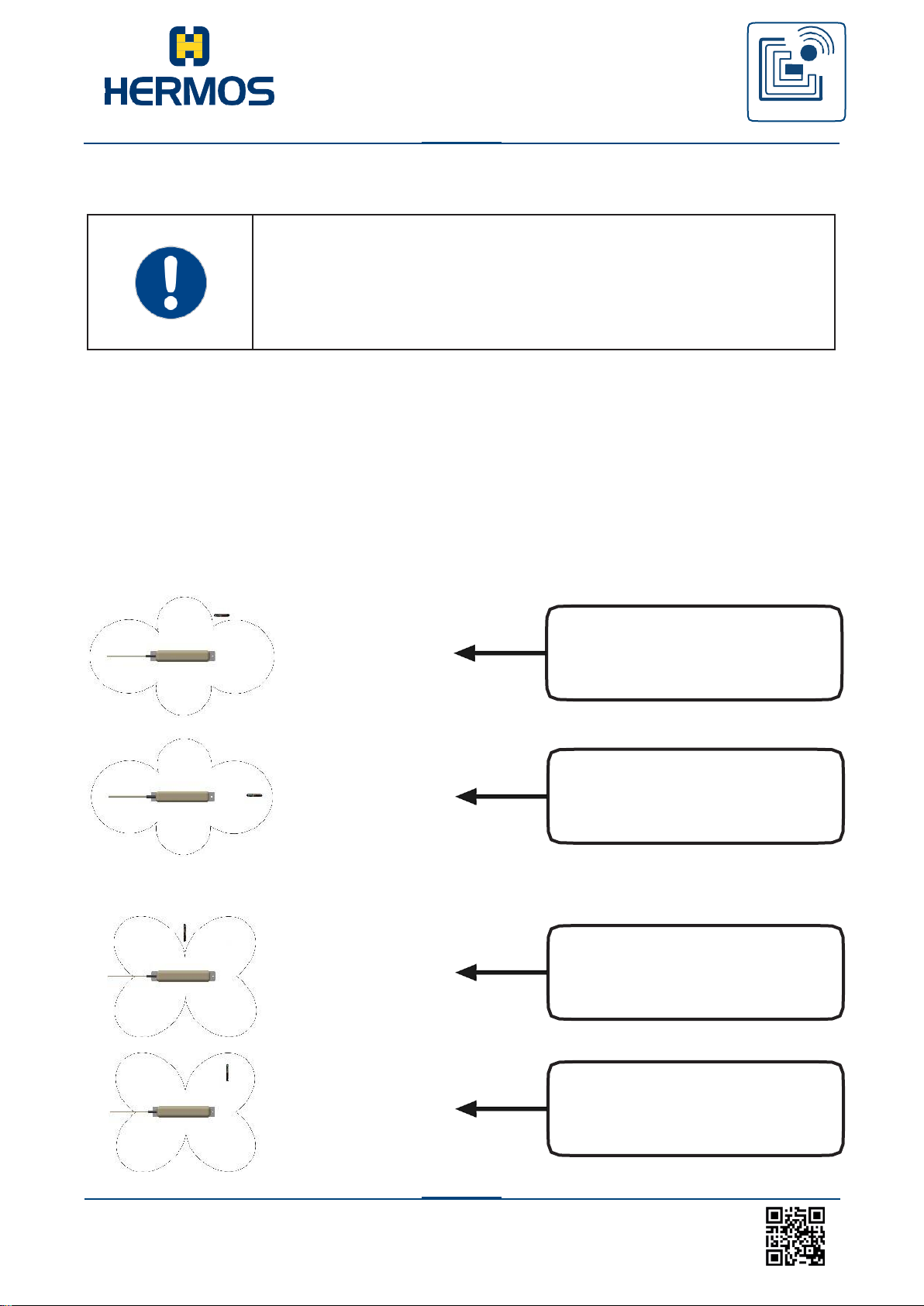
The removal and alignment of the transponder tot he antenna is critical to ensure reliable
reading and writing. The following diagram displays the optimum alignment and position of
the transponder to the antenna. After positioning, the antenna must be tuned to the
ambient conditions.
The tuning function can be started with the DIP switch 4.
Transponder parallel to the antenna axis:
Transponder vertical to the antenna axis:
Transponder is outside the
antenna range
Transponder is within the
antenna range
Transponder is outside the
antenna range
Transponder is within the
antenna range
Page 27
Customer manual
LFM 4x Reader
RFID
WE GENERATE SOLUTIONS
LFM 4x Reader Rev1.4
27
www.hermos.com
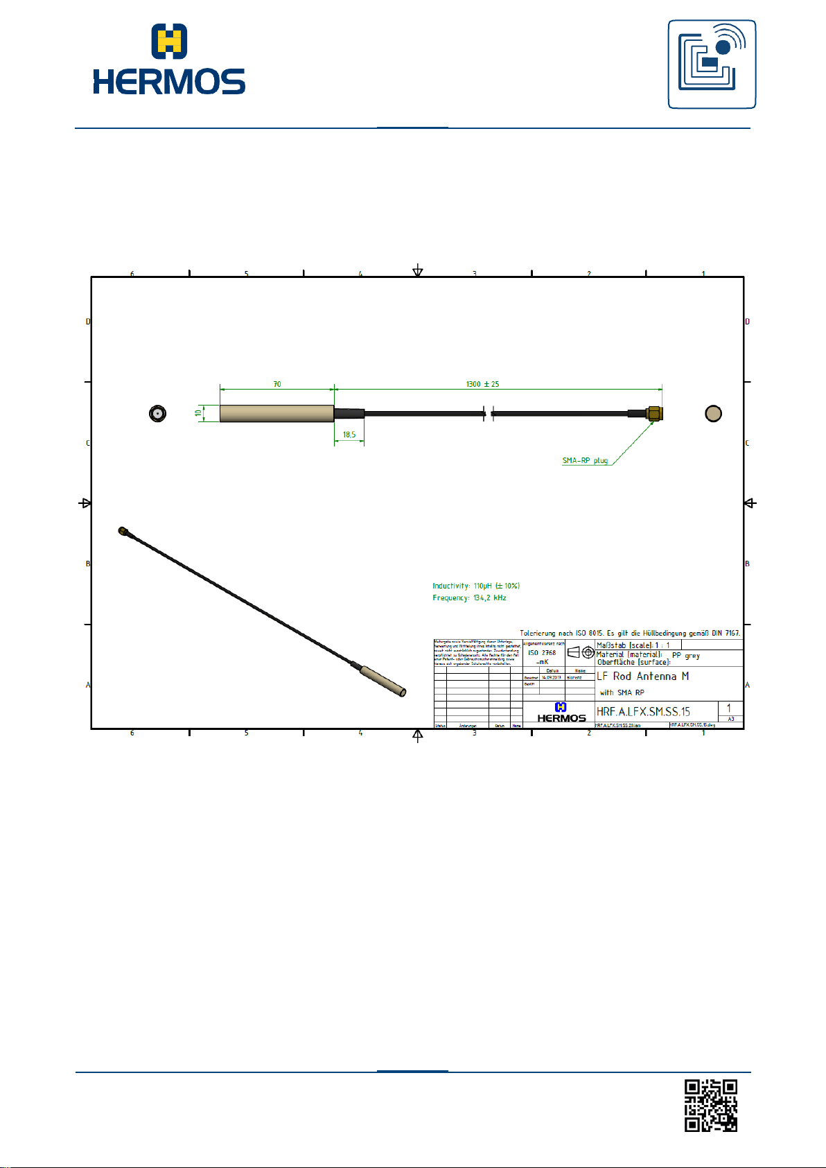
7.5.2 Rod Antenna M dimensions
Art.Nr. (HRF.A.LF.SM.SS.15)
Page 28
Customer manual
LFM 4x Reader
RFID
WE GENERATE SOLUTIONS
LFM 4x Reader Rev1.4
back to the table of contents
27
www.hermos.com
Use the antennas and antenna cable from the manufacturer to ensure
optimum reading and writing ranges.
There are risks if the device is supplied with the incorrect voltage.
Only use cables, plugs and adapters from the manufacturer.
Observe power ratings provided in the technical data.
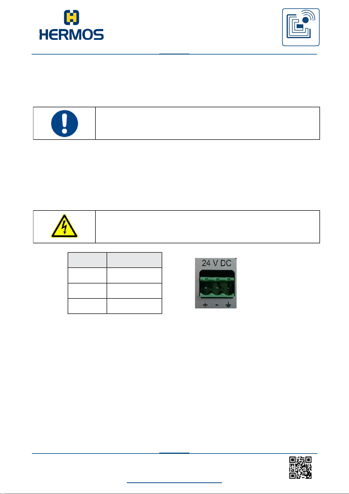
PIN
Signal
1
+24V DC
2
0 V
3
GND
7.5.3 Connecting the antenna
Connect the antenna at the antenna connection at the rear of the
reading unit. Observe the label here.
7.6 Power Supply
The device can be connected to the system‘s internal power supply or an external power
supply.
If the device is connected to the power supply, the power LED lights up.
Page 29
Customer manual
LFM 4x Reader
RFID
WE GENERATE SOLUTIONS
LFM 4x Reader Rev1.4
back to the table of contents
28
www.hermos.com
Switch
Function
1
Antenna connection selection
off, off … Antenna connection 1
off, on … Antenna connection 2
on, off … Antenna connection 3
on, on … Antenna connection 4
2
3
off: Operation mode
on: Activated test mode
4
DIP 3 off: Deactivated test mode
off->on Start Antenna Tuning
DIP 3 on: Activated test mode
Selection of the test function:
off = Read, on = Write
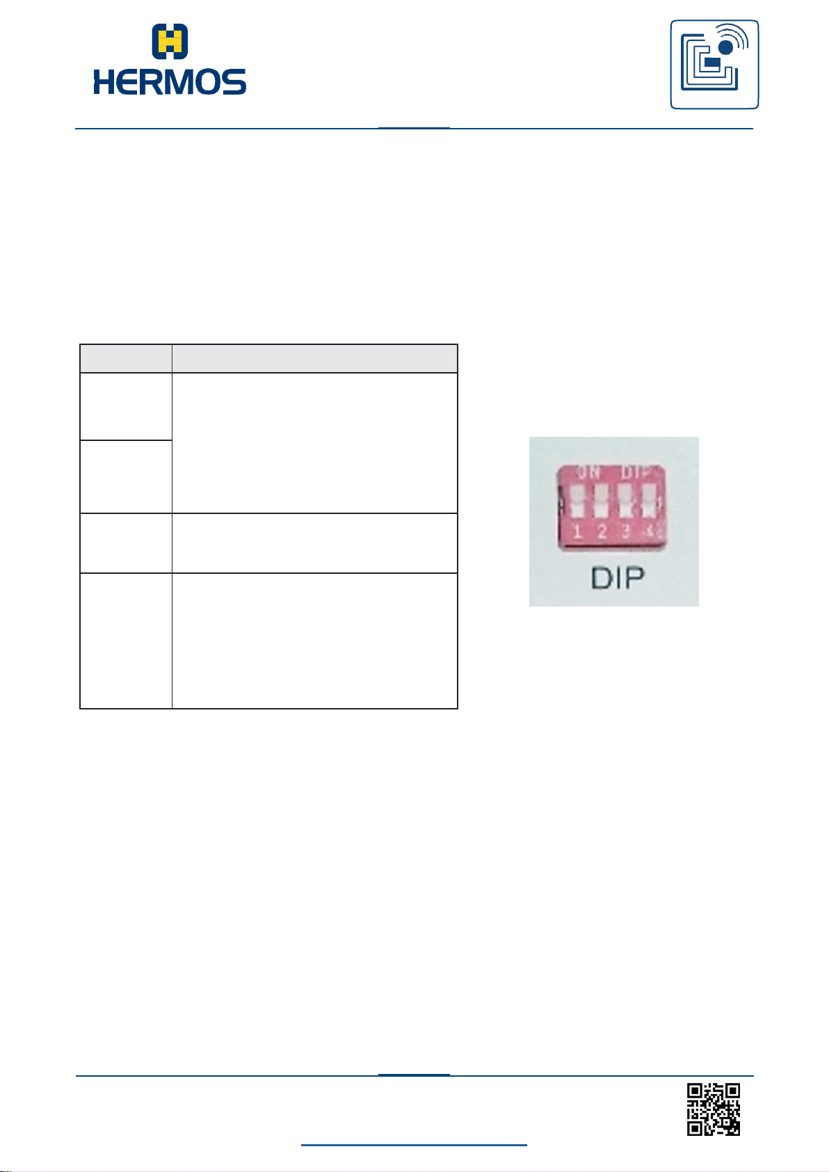
7.7 DIP-switch
Test mode can be activated via the 4 DIP switches on the device. In test mode, a
continuous reading operation is performed at the set antenna port and the result
of the reading operation is displayed on the status LED.
The test mode is activated by setting DIP switch 3DIP switch 4 can be used to
select between test reading and test writing The selection of the antenna port is
changed using the DIP switches 1 and 2.
Page 30
Customer manual
LFM 4x Reader
RFID
WE GENERATE SOLUTIONS
LFM 4x Reader Rev1.4
back to the table of contents
29
www.hermos.com
PIN
Signal
1
NC
(Optional GND)
2
TxD
3
RxD
4
NC
5
GND
6
NC
7
NC
8
NC
9
NC
(Optional +5V)
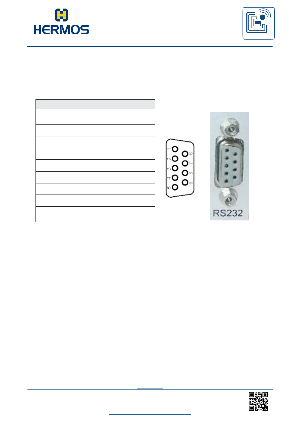
7.8 RS232 connection
The serial interface is implemented as a Sub-D plug connector (9-pin). A serial connection
line (1:1 circuit) can be used.
Page 31
Customer manual
LFM 4x Reader
RFID
WE GENERATE SOLUTIONS
LFM 4x Reader Rev1.4
back to the table of contents
30
www.hermos.com
Signal
Baudrate
19200
Datenbits
8
Stoppbits
1
Parität
ASCII: Even
SECS/HSMS: None
8.Commissioning
8.1 Operating conditions
The following requirements must be fulfilled for smooth device operation.
1. The operating temperature must be within the scope of the values
specified in the technical data.
2. The device must be connected to the
power supply (provide PoE is not used).
3. An antenna must be properly connected to the reading device.
4. A transponder must be within the reading and writing ranges of
the connected antenna.
5. For normal operation, deactivate test mode after
installation. (All DIP switches off).
8.2 The serial interface parameters
The following settings of the serial interfaces are set on delivery. The baud rate
can be changed in the SECS protocol with the parameter 0x01. If you want to
change the baud rate in the ASCII protocol, then please contact the manufacturer
HERMOS.
Page 32
Customer manual
LFM 4x Reader
RFID
WE GENERATE SOLUTIONS
LFM 4x Reader Rev1.4
back to the table of contents
31
www.hermos.com
8.3 Parameter of the ethernet interface
The unit is connected to the customer network via a 10/100BaseT Ethernet interface. The
DHCP (Dynamic Host Configuration Protocol) is activated on delivery.
If there is not a DHCP server available in your network, a random IP address is set from
the Zero- Conf range (169.254.0.0/16) and operations must still be performed to obtain an
IP address. If an IP address could be obtained or with a static IP address, the device can
be connected via TCP / IP port 3241 in the delivery state.
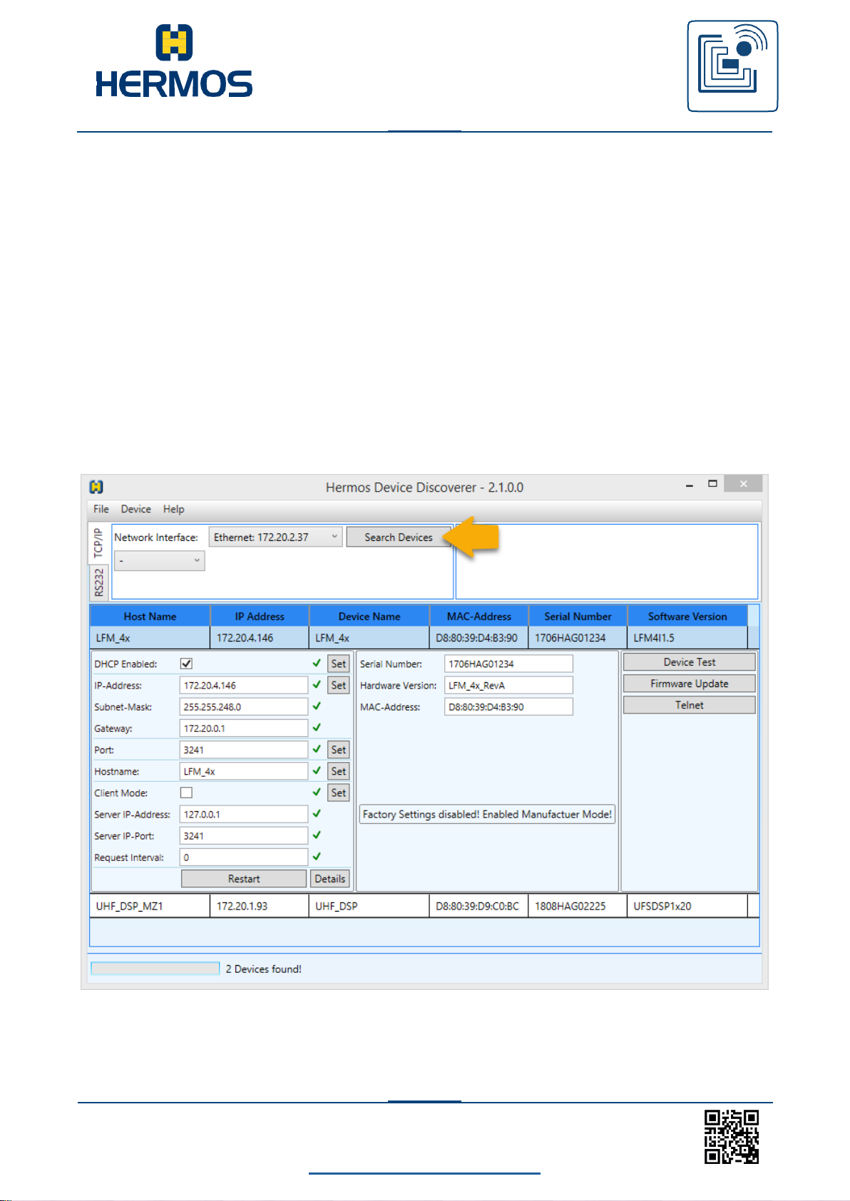
The HERMOS „DeviceDiscoverer“ is available for configuring the network setting.
8.3.1 Change networksettings with DeviceDiscoverer
HERMOS components can be found in the LAN network and settings can be
easily changed using the „DeviceDiscoverer“.
Page 33
Customer manual
LFM 4x Reader
RFID
WE GENERATE SOLUTIONS
LFM 4x Reader Rev1.4
back to the table of contents
32
www.hermos.com
1. Select your network interface if you have several options on your PC.
2. Your network is automatically scanned for all HERMOS reading devices using the
„Search Devices“ button.
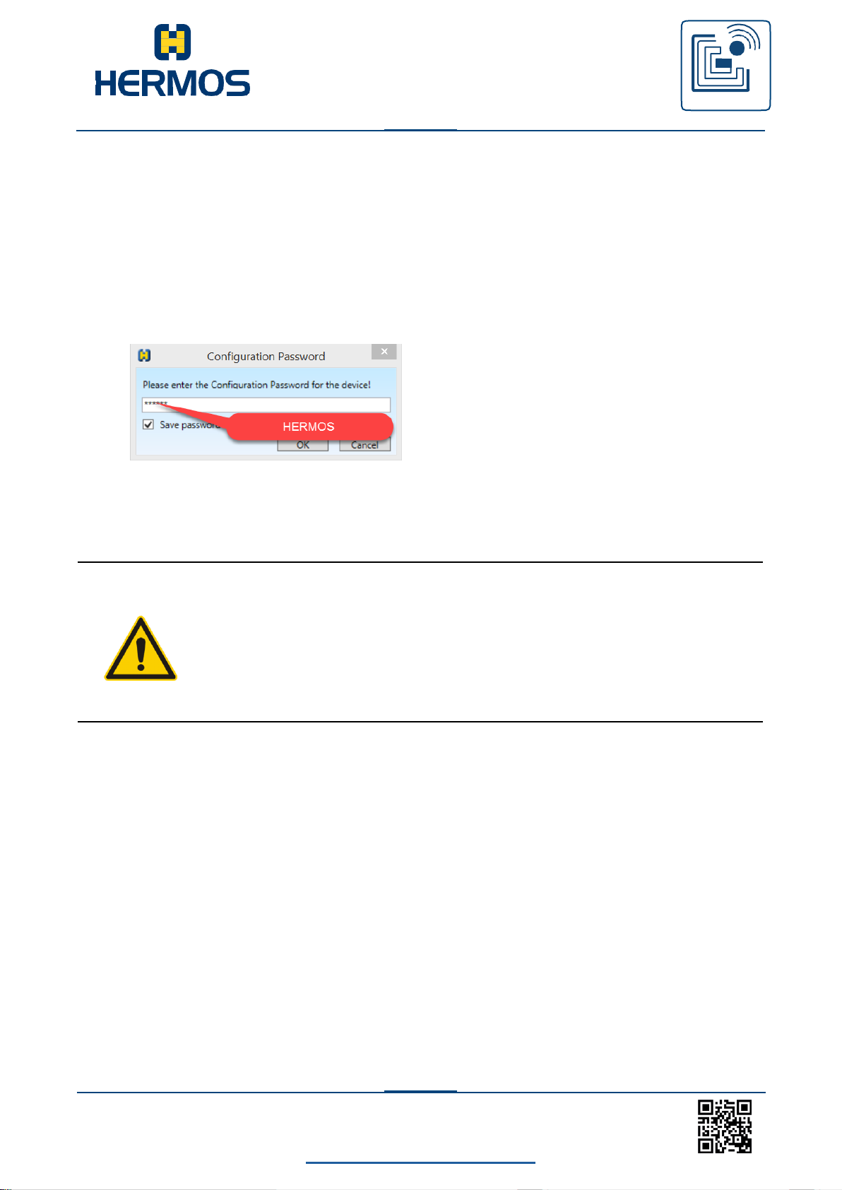
3. Select the desired reading device in the list to open the network settings.
Here, you can edit the network settings and apply them to the
reading device by pressing the respective button. Use „HERMOS“ if
you are asked to enter a password!
After parameters are changed, the reading device reboots and can be read in using
„Search Devices“.
CAUTION
Changing network settings generally cause the reading
device to reboot. This closes an existing HSMS host
connection.
Page 34
Customer manual
LFM 4x Reader
RFID
WE GENERATE SOLUTIONS
LFM 4x Reader Rev1.4
back to the table of contents
33
www.hermos.com
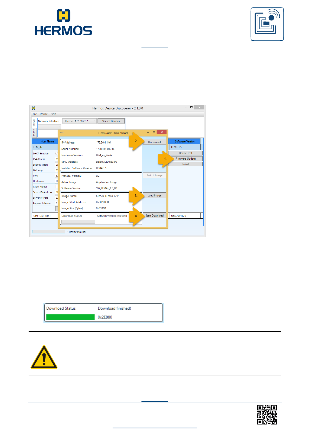
8.3.2 Firmware update with DeviceDiscoverer
Firmware updates can also be performed using the HERMOS „DeviceDiscoverer“. Start
the tool with administrator rights and scan the network for all HERMOS devices.
To do an update, mark the desired reading device and select „Firware Update”.
Use „HERMOS“ if you are asked to enter a password!
1. Click the "Firmware Update" button to open the new Firmware Download window for
the selected reader.
2. It is usually not necessary to open the download connection as this
happens automatically. Otherwise, pressing the Connect button will open
the download connection.
3. Select the new firmware file using the load image button.
4. Start the download process.
Wait until the „Download Finished“ message appears.
CAUTION
During the download process, do not disconnect the power supply or interrupt the
network connection.
Page 35
Customer manual
LFM 4x Reader
RFID
WE GENERATE SOLUTIONS
LFM 4x Reader Rev1.4
back to the table of contents
34
www.hermos.com
Len
Actionr
CMD
optional
Headnr
opt. Daten
Description
0x02
0x00
0x4E (‚N‘)
Trigger Readerreset
0x02
0x01
0x56 (‚V‘)
Get Softwareversion
0x02
0x02
0x53 (‚S‘)
Get UDP Revision
0x04
0x03
0x46(‚F‘)
0x01
0x1A (Parnr.)
Get Parameter Head 0x01 Par. 0x1A
0x04
0x04
0x50(‚P‘)
0x01
0x07, 0x03
Set Parameter Head 0x01 Par. 0x07
Value 0x03
0x04
0x05
0x49(‚I‘)
0x01
0x10 (auto
tune)
Trigger Tuning (0x10 auto tune)
Head 0x01
0x05
0x06
0x58(‚X‘)
0x01
0x02, 0x08
Trigger Read Page 0x02 Length 0x08
at Head 0x01
8.3.3 Test Device with DeviceDiscoverer
This feature is not yet supported by all HERMOS readers and is only available for the
LFM4x as of software version V1.5.
Readers can also be tested with the HERMOS "Device Discoverer" if you have one
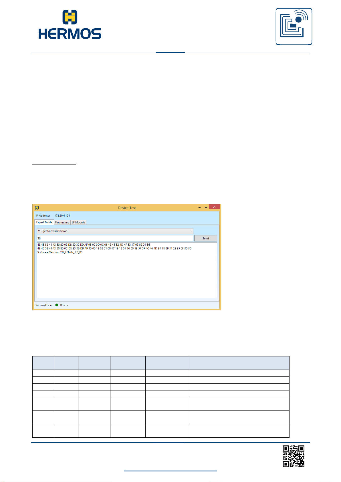
support feature. Start the tool with administrator rights and search for the HERMOS device
under test in the network. Select the desired reader and select the "Device Test" button
independently of your interface. A further "Device Test" view is opened with which the
addressed reader can be tested via the UDP protocol without having to disconnect any
existing TCP / IP connection.
Expert Mode:
In the "Expert Mode" tab you can select from a list of test commands and send this after
any modification. The Trace window below shows all traffic generated when testing with
UDP. The success code of the response message is displayed in the status bar at the
bottom left.
Below is the structure of the UDP action commands to own test actions on the reader
to be able to define. Depending on the command, the head number and data may be
optional data elements
Structure of the request message:
Page 36
Customer manual
LFM 4x Reader
RFID
WE GENERATE SOLUTIONS
LFM 4x Reader Rev1.4
back to the table of contents
35
www.hermos.com
Länge
Actionr
CMD
Success-Code
opt.Headnr
opt. Daten
Erklärung
0x03
0x00
0x6E (‚n‘)
0x00 (ok)
ResponseTriggered
Reset
0x12
0x01
0x76 (‚v‘)
0x00 (ok)
0x53, 0x57,…,
0x30
Response Get
Softwareversion
0x04
0x02
0x73(‚s‘)
0x00 (ok)
0x01
Response Get UDP
Revision 0x01
0x06
0x03
0x66(‚f‘)
0x00 (ok)
0x01
0x1A, 0x0F
Response Get
Parameter Head 0x01
Par 0x1A Value 0x0F
0x03
0x03
0x66(‚f‘)
0x36 (invalid
parnr)
Response Get
Parameter
Error 0x35 Invalid
parnr
0x04
0x04
0x70(‚p‘)
0x00 (ok)
0x01
Response Set
Parameter Head 0x01
0x04
0x04
0x70(‚p‘)
0x37(invalid
value)
Response Set
Parameter
Error 0x37 Invalid
value
0x05
0x05
0x69(‚i‘)
0x00 (ok)
0x01
0x04
(Tuningwert)
Response Tuning
Head 0x01 Wert 0x04
0x03
0x05
0x69(‚i‘)
0x35 (invalid)
Response Tuning
Error 0x35 Invalid
Value
0x0D
0x06
0x78(‚x‘)
0x00 (ok)
0x01
0x02,
0x31…0x38
Response Read Head
0x01
Page 0x02
Data 0x31…0x38
0x03
0x06
0x78(‚x‘)
0x34 (No Tag)
Response Read
Error 0x34 NoTag
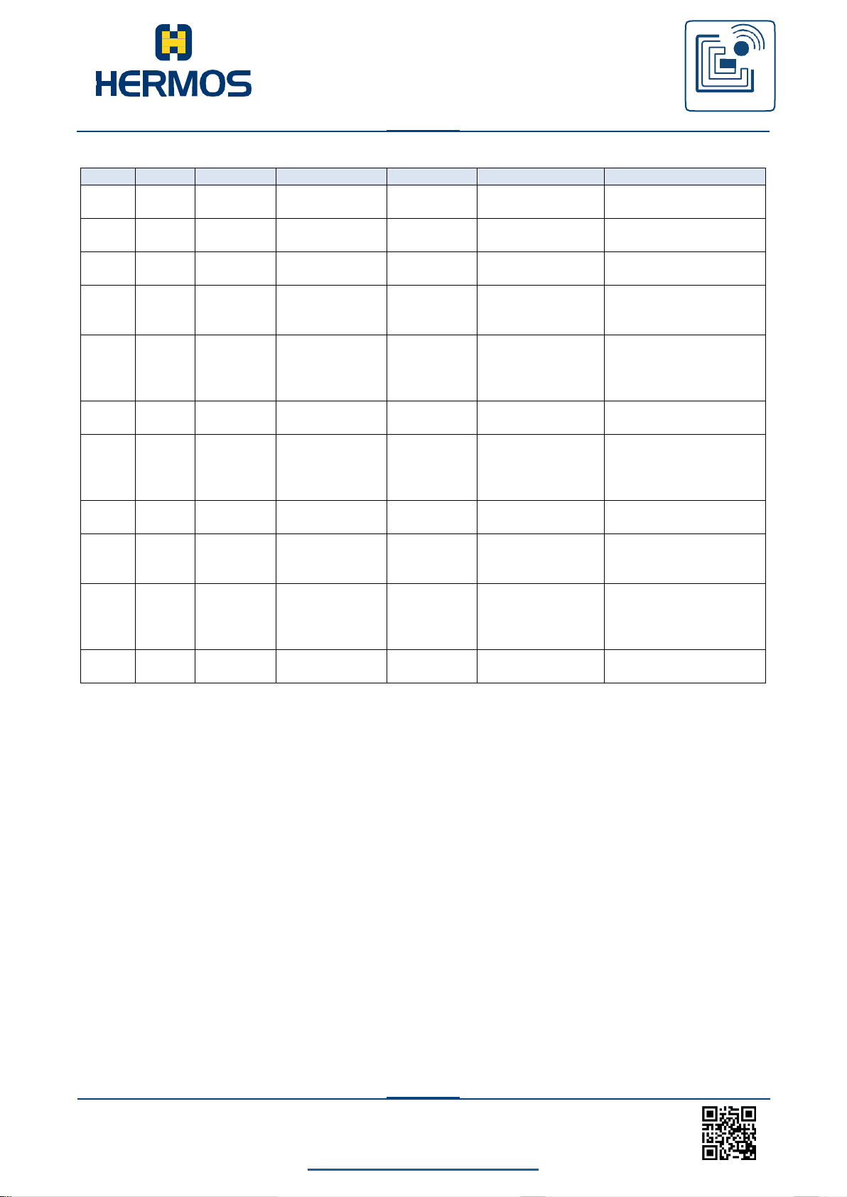
Structure of the response message:
A success code of 0x00 in the response message indicates the correct execution of the
UDP action commands, otherwise an error has occurred.
Page 37
Customer manual
LFM 4x Reader
RFID
WE GENERATE SOLUTIONS
LFM 4x Reader Rev1.4
back to the table of contents
36
www.hermos.com
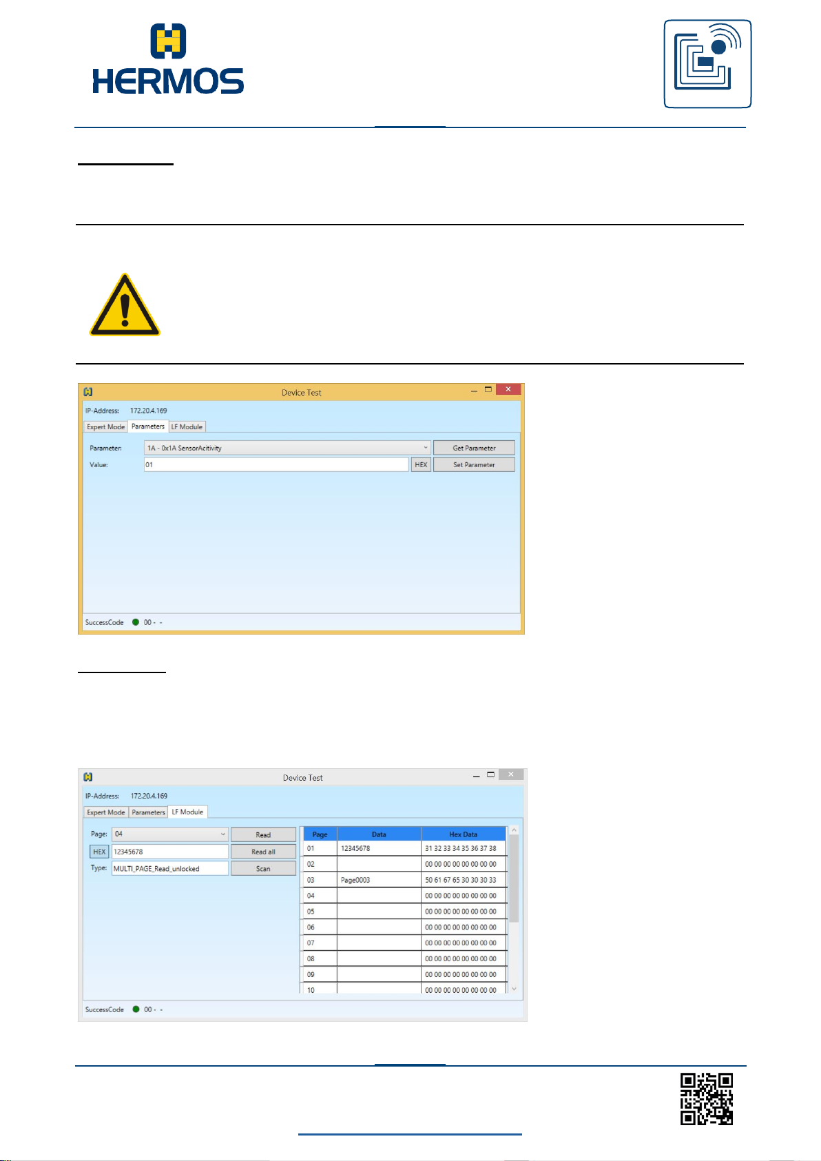
Parameters:
In the "Parameters" tab you can choose from a list of parameters that can be read and
written.
CAUTION
When setting and reading parameters, it must be carefully considered
which communication protocol is currently set. Some parameters are
defined differently in different protocols.
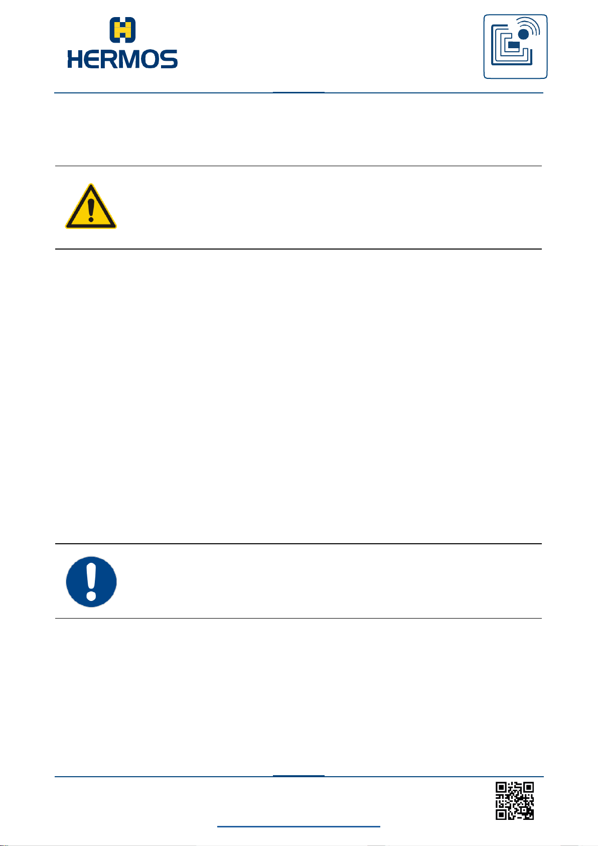
LF Module:
In the register "LF Module" a test reading can be carried out. One or more pages of a
multipage transponder can be read out. The success code of the triggered reading is
displayed in the status bar at the bottom of the window. Via a scan, the first page of every
readable 134.2 kHz LF transponder is read out and displayed.
Page 38
Customer manual
LFM 4x Reader
RFID
WE GENERATE SOLUTIONS
LFM 4x Reader Rev1.4
back to the table of contents
37
www.hermos.com
9. Operating
9.1 Operating personnel
The device should only be operated by specially trained personnel. If you have any
doubts about the required qualifications, please contact the manufacturer.
The operation of the device without special expertise can result in damages to the
device or on connected devices.
9.2 Protocol change
9.2.1 General
To communicate with a connected host system, the reader supports ASCII or SECS /
HSMS protocols. The protocol selection takes place by means of automatic protocol
recognition.
The currently set protocol is displayed on the status LED during the boot process.
SECS: The red LED goes on briefly after self test
ASCII: The yellow LED goes on several times
9.2.2 Automatic protocol detection
The reader automatically adjusts to the protocol used by checking and evaluating the first
message after a reset. The interface is changed accordingly when the protocol is changed
and reinitiali- zed. This process can take several seconds. Already sent messages are lost.
The newly recognized protocol is used for further communication. A renewed change is
only pos- sible after another reset. Automatic protocol detection can be disabled by setting
parameter 98 (0x62).
If the reader receives undefined or random characters, this may result in an
accidental protocol change.
Automatic protocol detection can be deactivated in parameter 98 (0x62).
Page 39

Customer manual
LFM 4x Reader
RFID
WE GENERATE SOLUTIONS
LFM 4x Reader Rev1.4
back to the table of contents
38
www.hermos.com
9.3 Addressing the antenna port
The reader LFM 4x is equipped with 4 antenna ports. Each of these ports has its own
antenna tuning with which the connected antenna is tuned to the ambient conditions.
In the set protocol, the read or write commands are always executed by port. The 4 antenna
ports from 1 to 4 are numbered consecutively and are addressed accordingly in the logging
command.
In the ASCII protocol, the reader ID decides on the selection of the antenna port.
The reader ID („1“ to „4“) responds to the respective antenna port 1 to 4. Depending on the
Factoryparameterset, it is possible to select the value range of the reader ID from „0“ to „3“ or
from „1“ to „4“.
In the SECS protocol, the target ID is used to select the antenna port: Target ID „01“ to „04“
responds to the respective antenna port 1 to 4.
For customer-specific solutions, another reader (eg HFS ESN) can be connected to the
RS232 interface. This reader is then used to communicate via the Target ID „05“ or Reader
ID „05“.
Page 40

Customer manual
LFM 4x Reader
RFID
WE GENERATE SOLUTIONS
LFM 4x Reader Rev1.4
back to the table of contents
39
www.hermos.com
9.4 Customer Factoryparametersets
The reader LFM 4x can be delivered with a few Factoryparametersets. The settings of the
Factoryparameterset is part of the factory settings and can only be changed by Hermos. If
customer needs another Factoryparameterset setting, please ask Hermos for the
necessary steps. The installed Factoryparameterset can be read by parameter 64 (use
command “G164”).
Factoryparameterset 0: (standard ASC-I1 mode)
The antenna will be addressed by the ReaderID or TargetID „1“ to „4“.
At the rs232 connector a HFS ESN reader is connected and can be adressed by ReaderID
“5”. For SECS protocol there is no MID area defined.
Factoryparameterset 1: (standard ASC-I1 mode)
The antenna will be addressed by the ReaderID or TargetID „1“ to „4“. For SECS protocol
there is no MID area defined.
The rs232 connector can be used for serial host communication.
Factoryparameterset 2: (standard ASC-I1 mode)
The antenna will be addressed by the ReaderID or TargetID „1“ to „4“.
For SECS protocol the default MID area of 2 pages / 16 characters is defined. The rs232
connector can be used for serial host communication.
Factoryparameterset 3: (ASC-W1 mode)
The antenna is addressed by the ReaderID „0“ to „3“, or TargetID „1“ to „4“. For SECS
protocol there is no MID area defined.
The rs232 connector can be used for serial host communication.
For the TCP/IP communication the complete end packet of the ASCI-I1 protocol will be
transmitted (end character and 4 bytes checksum).
P-command: The parameter value will be interpreted as hexadecimal value.
The additional F-command can be used to deliver the parameter value with hexadecimal
interpretation. X/R/W-command: The page value will be interpreted as hexadecimal value.
Errors will be send with the command “E”. With default settings a confirmation has to be
send. The additional B-command can be used for signal the detection of an object.
Factoryparameterset 4: (standard ASC-I1 mode)
The antenna will be addressed by the ReaderID „0“ to „3“ or TargetID „1“ to „4“.
For the SECS protocol, the standard MID range of 2 pages / 16 characters is defined. The
RS232 port can be used for serial host communication.
Factoryparameterset 5: (standard ASC-I1 mode)
The antenna will be addressed by the ReaderID „0“ to „3“ or TargetID „1“ to „4“.
For the SECS protocol, the standard MID range of 2 pages / 16 characters is defined. The
RS232 port can be used for serial host communication.
This mode supports the 24 volt I / O module with 6 sensors and 8 outputs. The two
additional sensors are represented by an extended range for ReaderID or Portnumber
PTN.
Page 41
Customer manual
LFM 4x Reader
RFID
WE GENERATE SOLUTIONS
LFM 4x Reader Rev1.4
back to the table of contents
40
www.hermos.com
Packet header
Message data
Packet end
Packet header
Start character
Length 1 (high byte)
Length 2 (low byte)
Packet header
Start 1
Start 2
Length 1
Length 2
Length 3
Length 4
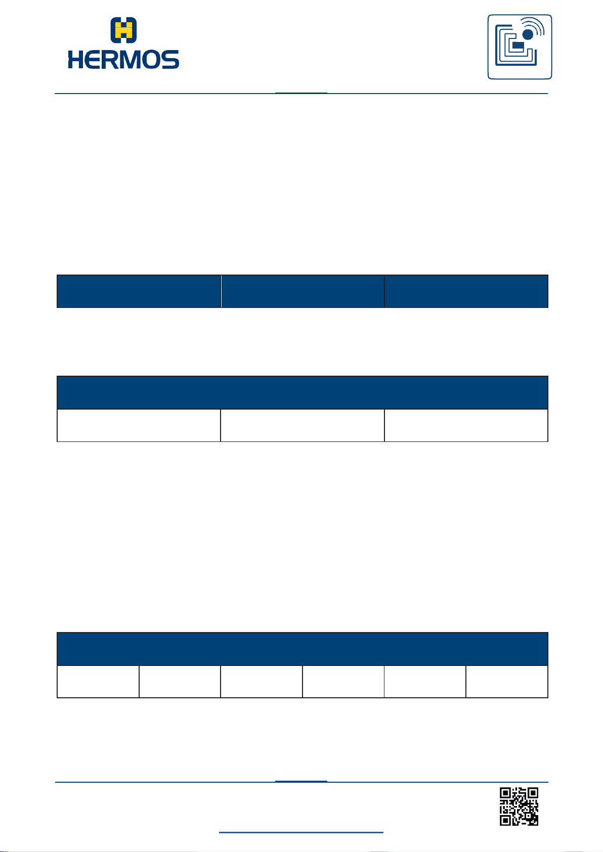
10. ASCI-I1 Communication protocol
10.1 Structure of the communication protocol
The communication is carried out via ASCII packets.
After each command to the reading device, a specific reply is transmitted. We recommend
waiting for this reply before transmitting a new command.
10.2 Packet content
Each message packet consists of a packet header (header = 3 characters), the message
data (2 or more characters) and the packet end.
Packet header
The packet header contains a start character and the message length. The message length
consists of 2 hexadecimal bytes and defines the number of characters in a message.
Start Start character (ASCII character „S“)
Length 1 High byte of the message length (ASCII character „0“-“F“)
Length 2 Low byte of the message length (ASCII character „0“-“F“)
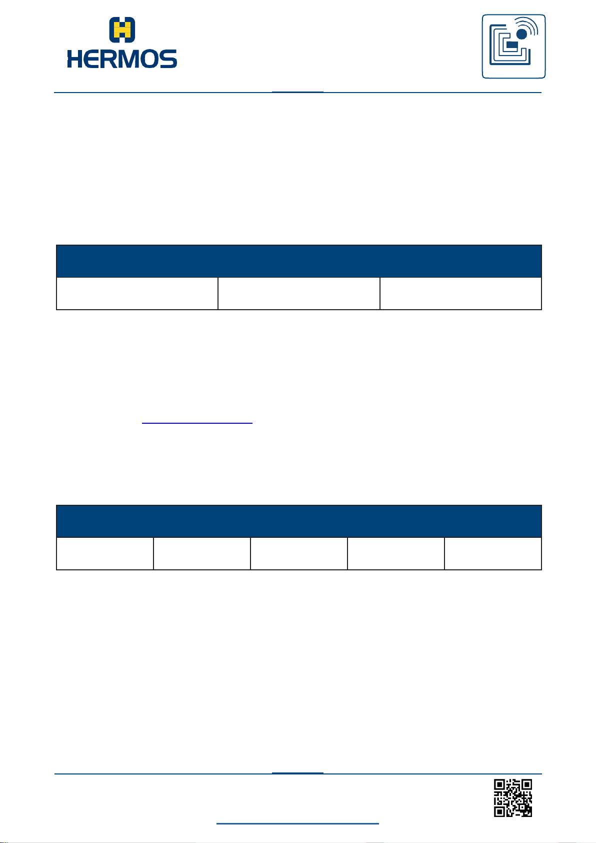
Advanced ASCII-format:
The advanced ASCII format is defined for ASCII messages whose message length
exceeds 255 characters. The packet header contains two start characters and the
message length. The message length consists of 4 hexadecimal bytes and defines the
number of characters in a message.
Start 1 First start character (ASCII-character „S“)
Start 2 Second start character (ASCII-character „X“ = advanced ASCII protocol)
Length 1 High byte of the message length (ASCII-character „0“-„F“)
Page 42
Customer manual
LFM 4x Reader
RFID
WE GENERATE SOLUTIONS
LFM 4x Reader Rev1.4
back to the table of contents
41
www.hermos.com
Message data
Command
Address
Data
Packet end
End character
Checksum 1
Checksum 2
Checksum 3
Checksum 4
Length 2 Byte packet length (ASCII character „0“-“F“)
Length 3 Byte packet length (ASCII character „0“-“F“)
Length 4 Low byte of the message length (ASCII character „0“-“F“)
Message data
The message contains a command character, a target or source address, the
number of the antenna port (head) and the actual message data.
The number of the antenna port is not required for all messages.
Command The command is defined by an ASCII character. (See protocol
commands)
Address Target/source address (ASCII characters „0“, „1“, …) *
Data The definition of the message data depends on the protocol command.
* Depending on Factoryparameterset, the readers are addressed via the address
„0 ... 3“ or „1 ... 4“.
Packet end
The end of the packet contains an end character and a checksum consisting of 4
characters.
End character ASCII end character <CR> (hex 0x0D).
Checksum 1 High byte XOR logic of all data (packet header, data and end character).
(ASCII character „0“…“F“)
Checksum 2 Low byte XOR logic of all data (packet header, data and end character).
(ASCII character „0“…“F“)
Checksum 3 High byte addition of all data (packet header, data and end character).
(ASCII character „0“…“F“)
Checksum 4 Low byte addition of all data (packet header, data and end character).
(ASCII character „0“…“F“)
Page 43
Customer manual
LFM 4x Reader
RFID
WE GENERATE SOLUTIONS
LFM 4x Reader Rev1.4
back to the table of contents
42
www.hermos.com
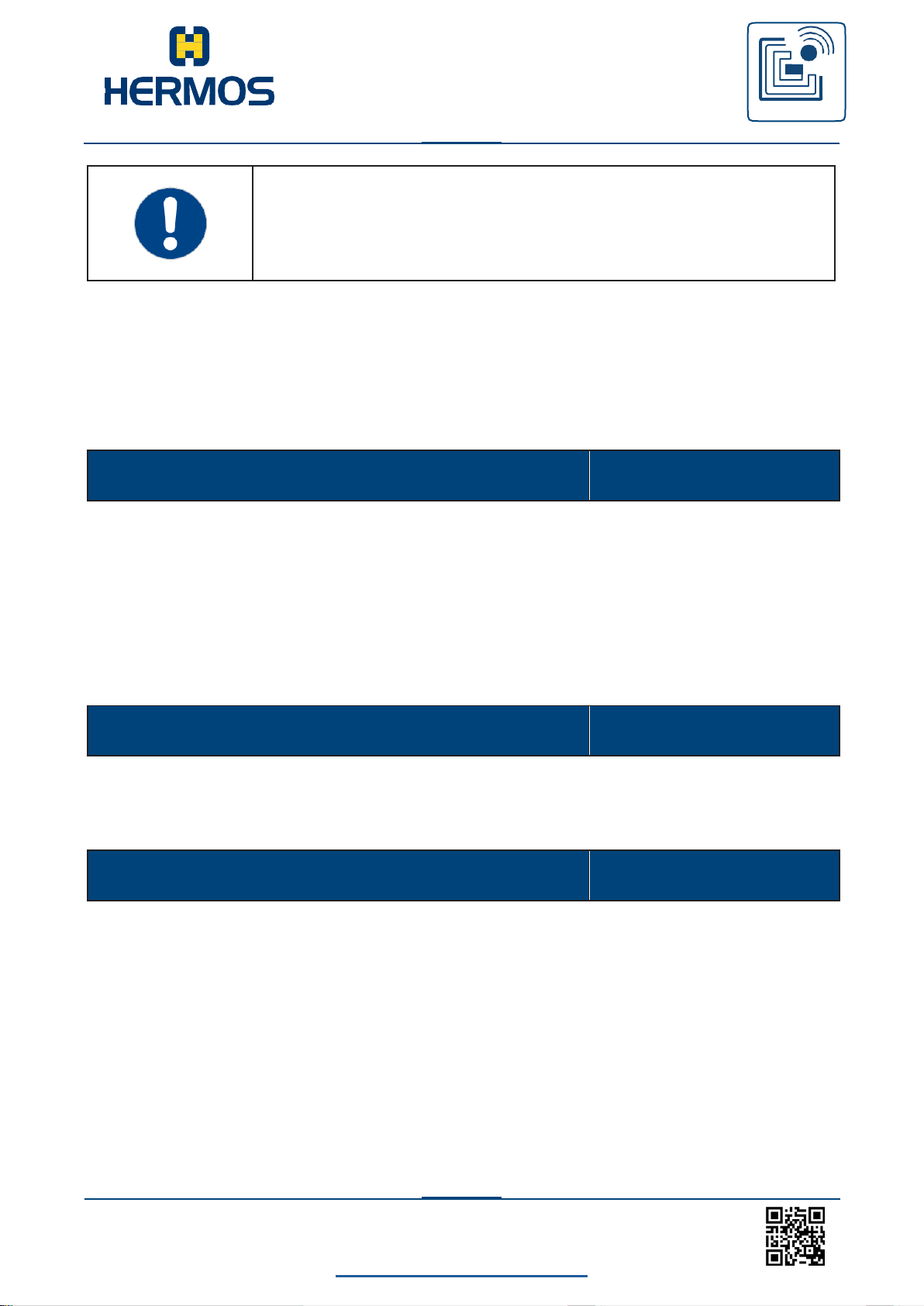
The checksum is not necessary when using the TCP/IP interface (No
transmission). The end character is only transmitted.
If the device is operated in ASC-W1 mode, the complete end packet is
transmitted (end character and 4 bytes checksum).
Tuning value
2 Byte
CMD
1 Byte
Data
16 Bytes
„08“ … automatic tuning from the reader
„10“ … manual tuning 0x00
„1F“ … manual tuning 0x0F
10.3 Data elements
The data elements that are used by default ASCII messages, which are described in the
message details section, are defined in this section.
The tuning value is a set value for the optimal antenna tuning. For optimum read and write
ranges, the value is automatically determined by the reader. The value is measured in 16
steps (0-F). He can also be targeted.
Example:
Command of the message, see table in Chapter “Commands“.
The data is represented in HEX format by 2 ASCII characters. The data always includes
every 8 bytes of the corresponding page of the transporter.
Example:
Transponder data in ASCII-Format „12345678“ (8 bytes)
Transponder data in HEX-Format 0x31 0x32 0x33 0x34 0x35 0x36 0x37 0x38
Data in message „3132333435363738“ (16 ASCII-characters)
Page 44

Customer manual
LFM 4x Reader
RFID
WE GENERATE SOLUTIONS
LFM 4x Reader Rev1.4
back to the table of contents
43
www.hermos.com
Output State
4 Bytes
Output Index
1 Byte
Example:
1
LED1 of the port
2
LED2 of the port
3
red status LED
4
yellow status LED
Output State
4 Bytes
Parameter No.
1 Byte
Example:
Parameter 1
Parameter 2
„1“
„2“
Parameter 15
“F“
Parameter Value
2 Bytes
The Output Index defines the index of the output of a Readerhead that is addressed. Each
Readerhead has 2 LEDs.
The data element shows or sets the current status of the outputs.
The Data Element Output State includes the status of each output on the reader. The
status is displayed as 1 byte for each sensor.
0
1
2
3
4
Switch off the output permanently
Switch on the output permanently
output flashes with approx. 1 Hz
output remains unchanged
output flashes with approx. 2 Hz
The number of the parameter is displayed as an ASCII character (1 byte) in HEX format.
With single-digit parameter numbers from „0“ to „F“, the actual parameter value
can be decimal or hexadecimal depending on the mode.
In the standard ASC-I1 mode, the data element displays the value of a parameter
using 2 ASCII characters (2 bytes) in decimal format (“00” bis “99”).
Example: Value 45 „45“
In ASC-W1 mode the data element indicates the value of a parameter by means of 2
ASCII characters (2 bytes) in hexadecimal format („00“ to „FF“).
Example: Value 45 (decimal) “2D“(hexadecimal)
Page 45

LFM 4x Reader Rev1.4
back to the table of contents
44
www.hermos.com
Customer manual
LFM 4x Reader
RFID
WE GENERATE SOLUTIONS
Output State
4 Bytes
Reader-ID
1 Byte
Response-Code
4 Bytes
Page
1 Bytes
Example:
Page
1
„01“
Page
10
„10“
Page
17
„17“
Example:
Page
1
„01“ („81“ if page is locked)
Page
10
„0A“ („8A“ if page is locked)
Page
17
„11“ („91“ if page is locked)
Read/Only
“F0“
Read/Write
“F1“
Serial number
4 Bytes
The reader ID defines the address of the antenna port.
The reader LFM 4x can be read at all 4 antenna ports (1-4).
The antenna port is selected via the reader ID and is continuous.
In ASC-W1 -mode the 4 antenna ports with the reader ID „0“ to „3“ are addressed. General
messages also possible at address F (HF). Value range of 1-4, or 0-3.
This feature is not required for the individual device. This code is always „0000“.
The page of the transponder for a read / write operation is defined by 2 ASCII characters
(2 bytes) in decimal format
If the device is operating in ASC-W1 mode, the page should be interpreted in hexadecimal
form: The page of the transponder for a read / write operation is defined by 2 ASCII characters
(2 bytes) in hexadecimal format.
Contains 4 byte of the serial number.
The serial number is also on the adhesive label of the device.
Example: „1707HAG04660“ complete serial number
Decimal „04660“ (the last 5 characters of the complete serial
number) Hexadecimal serial number „1234“
The gateway ID is the last two digits and has the value 0x34
Page 46
LFM 4x Reader Rev1.4
back to the table of contents
45
www.hermos.com
Customer manual
LFM 4x Reader
RFID
WE GENERATE SOLUTIONS
Software version
16 Bytes
Timeout
2 Bytes
Command
Description
X
Read Data
R
Automatic Read
Command
Description
W
Write Data
The data item contains the software version currently used in the reader. The version string is
displayed with up to 16 characters.
Example: „4C464D3449312E35“ hex -String („LFM4I1.5“)
The data element Timeout defines the period of time that elapses until the LEDs are switched
off. The timeout is defined in hexadecimal notation.
When the timeout expires, the LED turns off.
Example: „00“ ... permanently on
„01“ bis „FF“ ... 1 s bis 255 s Timeout
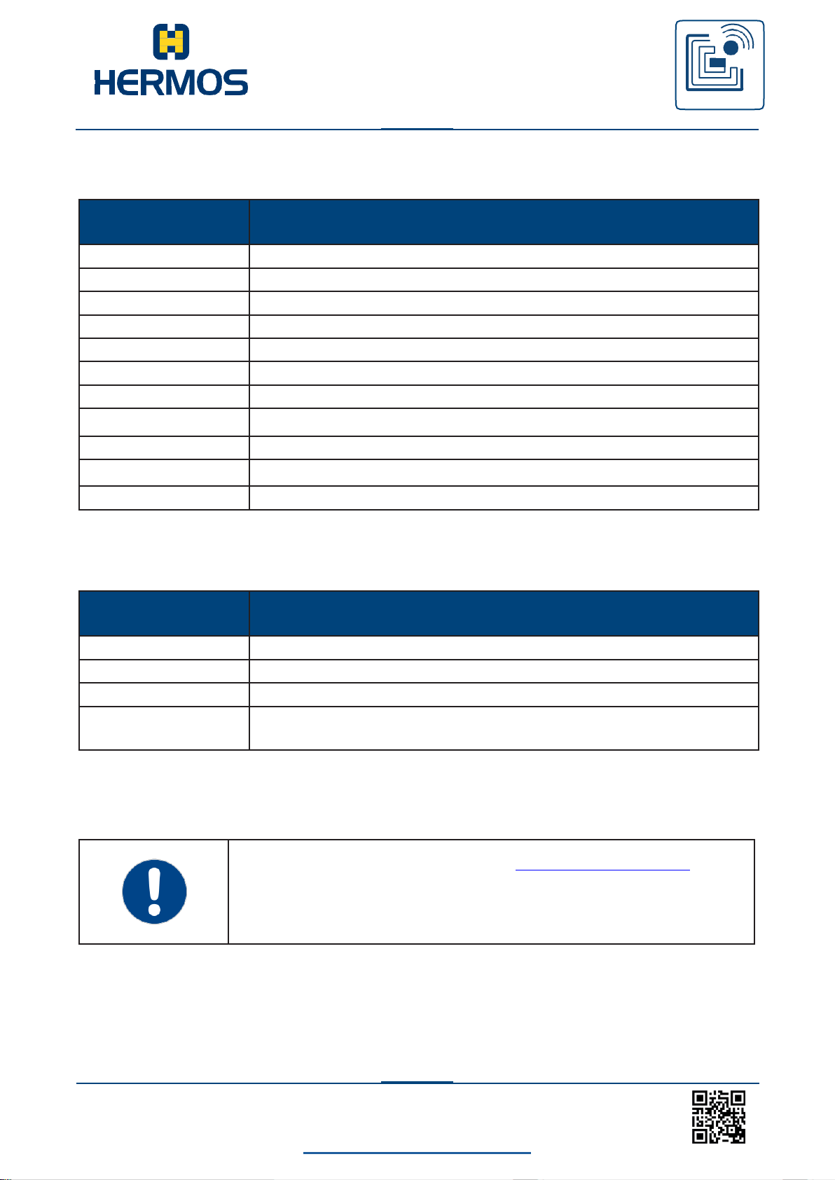
10.4 Protocol Commands
Read:
Write:
Page 47
LFM 4x Reader Rev1.4
back to the table of contents
46
www.hermos.com
Customer manual
LFM 4x Reader
RFID
WE GENERATE SOLUTIONS
Command
Description
G
Query Parameter
F
Query Parameter (Device is operated in ASC-W1 mode)
P
Set Parameter
N
Reset
e
Error message
E
Error message (Device is operated in ASC-W1 mode)
H
Heartbeat
V
Software-Version
L
Lock side of a transponder
l
Coordinate RF-modules
J
Querying the coordination of the RF-module
Command
Description
O
Set Output
Q
Query Output/Input State
A
Sensor event: Sensor removed
B
Sensor event: Sensor detected (Device is operated in ASC-W1
mode)
For customer-specific device variants (->Factoryparametersets),
another reader can be connected to the RS232 interface.
The commands specified for this device are not part of this
documentation.
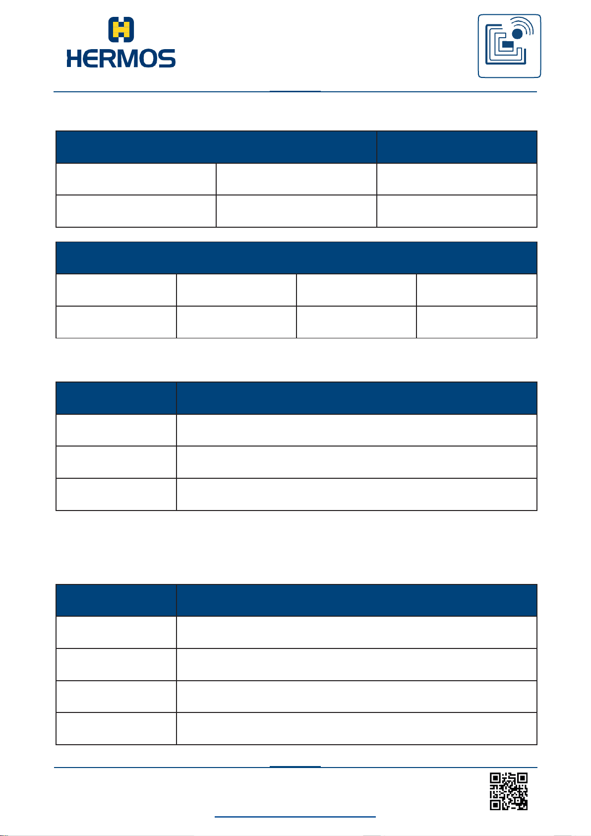
Device-Settings:
In- and Output:
Page 48
LFM 4x Reader Rev1.4
back to the table of contents
47
www.hermos.com
Customer manual
LFM 4x Reader
RFID
WE GENERATE SOLUTIONS
Host
Device
CMD
Reader-ID
Page
X
1 Byte
2 Bytes
Device
Host
CMD
Reader-ID
Page
Data
x
1 Byte
2 Bytes
16 Bytes
Page
Description
„01“ … „17“
Read # page
„98“
Read multiple pages to the end character or a blank character 1)
„99“
Read out all transponder data
Page
Description
„01“ … „11“
Read page # of a multipage transponder
„F0“
Read/Only transponder
„F1“
Read/Write transponder
„00“
Read the first page of all transponder types
10.4.1 X - Read data
The data element „page“ can have the following values:
1) „E“ or „F“ in ID, Bit 0…3 of the read ID
In ASC-W1 mode, the data element „page“ can have the following values:
Page 49
LFM 4x Reader Rev1.4
back to the table of contents
48
www.hermos.com
Customer manual
LFM 4x Reader
RFID
WE GENERATE SOLUTIONS
0
Reading the page defined in parameter 2 (readpage)
1
sequential reading of a transponder to the end character
(‚E‘ - end character or ‚F‘ empty) in ID bit 0 ... 3
2
Reading the entire transponder (all pages)
Device
Host
CMD
Reader-ID
Page
Data
R
1 Byte
2 Bytes
16 Bytes
Host
Device
CMD
Reader-ID
r
1 Byte
If there is no transponder in the reading range of the antenna, the reader repeats the reading
function several times before an error message is sent. The number of repetitions is defined in
parameter 4 (‚r / w maxrepeat‘). If reading is still not possible, the reader sends the error
message ‚no tag (4)‘ to the host after the repetitions have been carried out.
No confirmation is expected from the host.
For a multipage read request (98 or 99), the protocol is retried. At the end of reading, the
reader sends an additional packet.
If the sensor check is activated (parameter 1: readmode), the assignment of the external input
is checked before the initiation of a read process by the host. The reading process is only
started if the sensor is occupied, otherwise the error message ‚no tag (4)‘ is sent.
10.4.2 R – Automatic read
By assigning the external input, an automatic read operation can be triggered.
The command „R“ sends the read data to the host. The host then has to confirm the
message. Depending on the setting of the reader (parameter 1: readmode), the reader
reads the following pages:
Read Mode:
Page 50
LFM 4x Reader Rev1.4
back to the table of contents
49
www.hermos.com
Customer manual
LFM 4x Reader
RFID
WE GENERATE SOLUTIONS
Host
Device
CMD
Reader-ID
Page
Data
W
1 Byte
2 Bytes
16 Bytes
Device
Host
CMD
Reader-ID
w
1 Byte
When reading several pages (par. 1: readmode „tag“ or „everything“) the command is repeated
for each read page. The last package contains the command ‚R‘ and the reader ID.
The host expects a confirmation of the read data. If there is no confirmation from the host, the
command is repeated. (par.5: ‚RS232 repeat time‘, par.6: ‚RS232 maxrepeat‘).
If a reading is not possible, the reader automatically repeats the reading with the set
parameters. (par.3: ‚r / w delay time‘, par.4 ‚r / w maxrepeat‘).
If no reading is possible, the reader sends the error message ‚no tag (4)‘ to the host.
The delay time for the presence sensor can be set (parameter 0: ‚sensor delay‘).
An automatic reading is only possible if all messages to be confirmed have been confirmed by
the previous reading or the waiting time (par.5: ‚RS232 repeat time‘, par.6: ‚RS232 maxrepeat‘)
has elapsed after the last transmission.
10.4.3 W - Write data
The command W starts writing a defined data area of a transponder.
If there is no transponder in the write range of the antenna, the reader sends an
error message (error 4 - no transponder).
If the describing of the tag fails, the reader repeats the writing operation several times before
sending an error message. The number of repetitions is defined in parameter 4 (‚r / w
maxrepeat‘). If writing is still not possible, the reader sends the error message ‚no tag (4)‘ to the
host after the repetitions have been carried out.
If the sensor check is activated (parameter 1: readmode), the assignment of the external input
is checked before the start of the write process by the host. The write process is started only
when the sensor is busy, otherwise the error message ‚no tag (4)‘ is sent.
Page 51
LFM 4x Reader Rev1.4
back to the table of contents
50
www.hermos.com
Customer manual
LFM 4x Reader
RFID
WE GENERATE SOLUTIONS
Host
Device
CMD
Reader-ID
G
1 Byte
Device
Host
CMD
Reader-ID
Parameter No.
Parameter Value
g
1 Byte
1 Byte
2 Bytes
10.4.4 G – Query parameter
With the command „G“ the values of all public parameters of the device can be queried.
The reader sends an individual protocol packet for each available public parameter. After the
last parameter, the reader sends a last packet including the command ‚g‘ and the reader ID.
From the list of public parameters only the parameter 0 to 7 and parameter F will be send.
The values returned for the data item parameter value in the response are decimal values
(00-99). The values for the data item Parameter No. are hexadecimal values (0-F).
Page 52
LFM 4x Reader Rev1.4
back to the table of contents
51
www.hermos.com
Customer manual
LFM 4x Reader
RFID
WE GENERATE SOLUTIONS
Host
LF Device
CMD
Reader-ID
Parameter No.
F
1 Byte
1 Byte
Device
Host
CMD
Reader-ID
Parameter No.
Parameter Value
f
1 Byte
1 Byte
2 Bytes
In the case of two-digit hexadecimal parameter numbers (Parameter
No.), the parameter number and the parameter value double-digit
hexadecimal are also used in the response.
10.4.5 F – Query parameter
The command „F“ can be used to query the value of a public parameter of the device.
The reader sends an individual protocol packet for the requested public parameter.
The values returned in the response for the data elements parameter number and parameter
value are each hexadecimal values (0-F or 00-FF).
Page 53
LFM 4x Reader Rev1.4
back to the table of contents
52
www.hermos.com
Customer manual
LFM 4x Reader
RFID
WE GENERATE SOLUTIONS
Host Device
CMD
Reader-ID
Parameter No.
Parameter Value
P
1 Byte
1 Byte
2 Bytes
Device
Host
CMD
Reader-ID
p
1 Byte
For two-digit hexadecimal parameter numbers (Parameter No.), the
parameter value must always be sent in two digits hexadecimal.
10.4.6 P – Set parameter
The command „P“ can be used to change the value of individual parameters. After a
parameter has been successfully changed, the reader sends a confirmation message.
Depending on the Factoryparameterset selected, the data elements parameter number and
parameter value must be interpreted differently. For single-digit hexadecimal parameter no. the
following interpretations must be observed:
In the standard ASC-I1 protocol mode the data element „Parameter Value“ with decimal values
(00-99) has to be used. The values for the data item „Parameter No.“ are hexadecimal values
(0-F).
Only in ASC-W1 mode (Factoryparameterset 3) the data elements „Parameter No.“ and
„Parameter Value“ have to be used as hexadecimal values (0-F or 00-FF).
Page 54
LFM 4x Reader Rev1.4
back to the table of contents
53
www.hermos.com
Customer manual
LFM 4x Reader
RFID
WE GENERATE SOLUTIONS
Host
Device
CMD
Reader-ID
N
1 Byte
Device
Host
CMD
Reader-ID
n
1 Byte
10.4.7 N – Reset
The command N performs a reset of the hardware/software of the reader.
After performing the reset operation, the device sends a confirmation message.
After a hardware reset, a confirmation („n0“) is sent to the host.
If TCP / IP is used as the interface, the host will not receive an acknowledgment,
because an existing TCP/IP connection is interrupted by the reset.
Page 55
LFM 4x Reader Rev1.4
back to the table of contents
54
www.hermos.com
Customer manual
LFM 4x Reader
RFID
WE GENERATE SOLUTIONS
Device Host
CMD
Reader-ID
Error ID
e
1 Byte
1 Byte
Device Host
CMD
Reader-ID
Error ID
E
1 Byte
1 Byte
Host
Device
CMD
Reader-ID
e
1 Byte
10.4.8 e – Error message
This message is only available in standard ASC-I1 mode!
If an error occurs the device will send an error message with the respective error code.
Further information about error codes and the corresponding corrective measures can be found
in the chapter Error Codes.
10.4.9 E – Error message
This message is only available in ASC-W1 mode. If there is an error, the device sends an error
messa- ge with the appropriate error code to the host.
The reader expects a confirmation of the error message. If there is no confirmation from the
host, the command is repeated. (Par.5: ‚RS232 delay time‘, par.6: ‚RS232 maxrepeat‘).
More about error codes and the corresponding corrective measures can be found in the
chapter Error Codes.
Page 56
LFM 4x Reader Rev1.4
back to the table of contents
55
www.hermos.com
Customer manual
LFM 4x Reader
RFID
WE GENERATE SOLUTIONS
Host
Device
CMD
Reader-ID
H
1 Byte - also Reader ID F allowed
Device Host
CMD
Reader-ID
Serial number
Response-Code
h
1 Byte
4 Bytes
4 Bytes
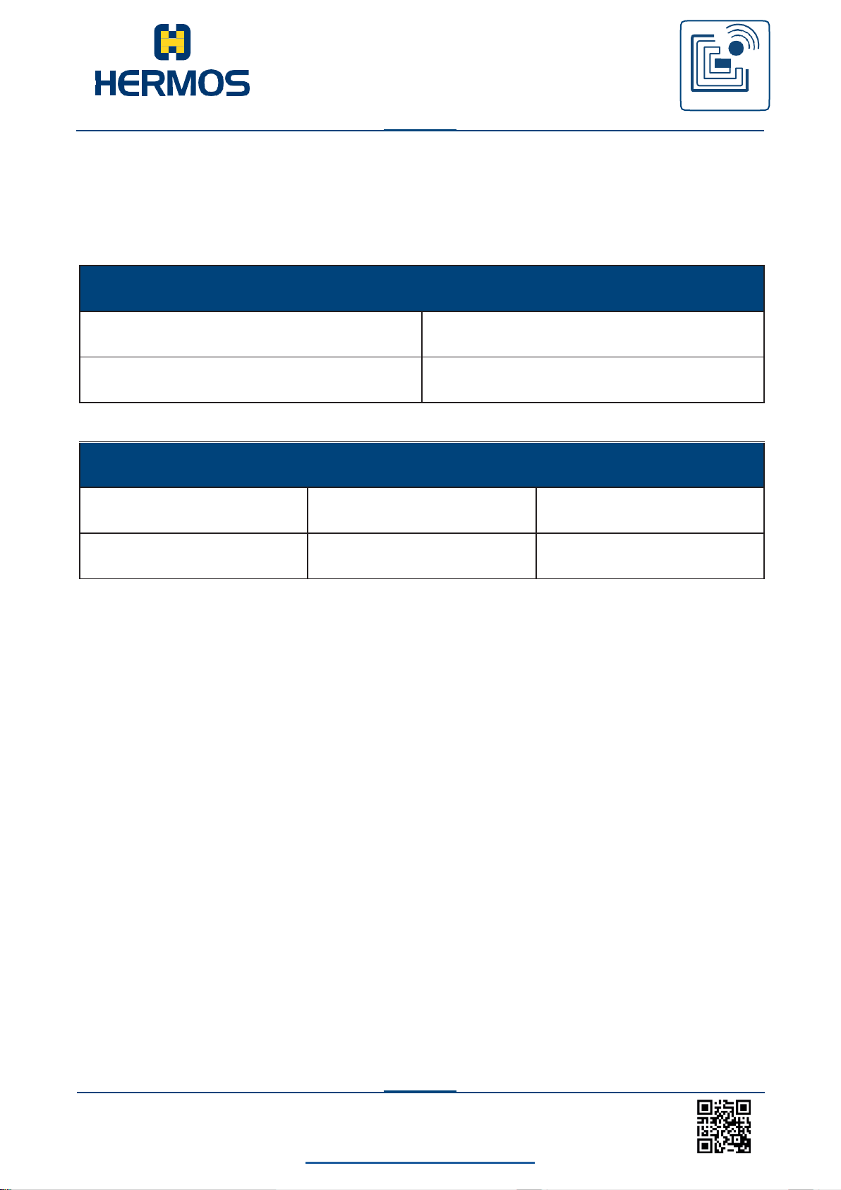
10.4.10 H – Heartbeat
The command „H“ sends a heartbeat request to the reader.
The reader responds with its serial number and a response code.
The heartbeat function can be performed for all 4 antenna ports (1-4).
If another reader is operated as a customer variant on the RS232 port, a heartbeat can be sent
to the external reader via reader ID „5“.
The response code is part of the protocol but is not used for this device. The response code is
always ‚0000‘.
Page 57
LFM 4x Reader Rev1.4
back to the table of contents
56
www.hermos.com
Customer manual
LFM 4x Reader
RFID
WE GENERATE SOLUTIONS
Host
Device
CMD
Reader-ID
V
1 Byte
Device Host
CMD
Reader-ID
Software version
v
1 Byte
16 Bytes
10.4.11 V – Query software version
The command V is used to query the software version of the device.
The 8 characters of the software version are represented by 16 ASCII characters. Each
character is described in hex format and transmitted by 2 ASCII characters.
Page 58
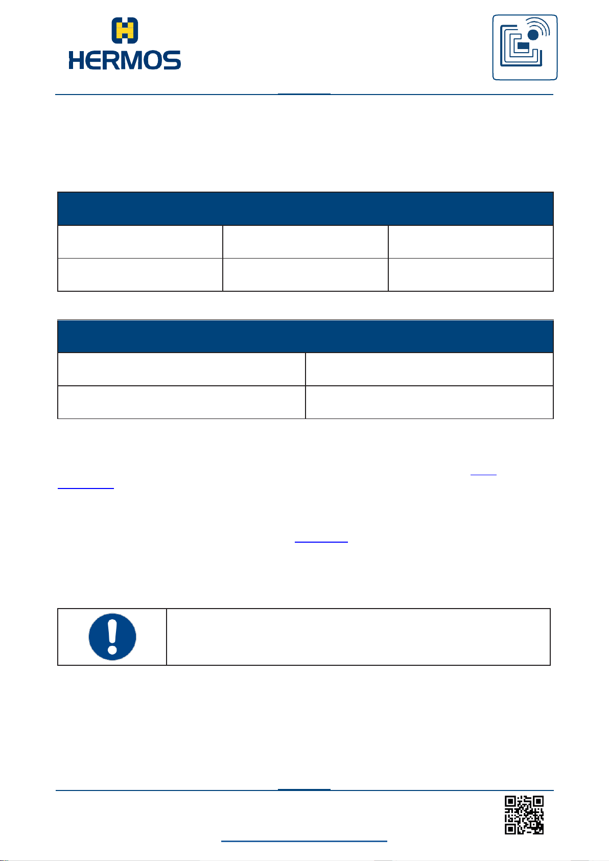
LFM 4x Reader Rev1.4
back to the table of contents
57
www.hermos.com
Customer manual
LFM 4x Reader
RFID
WE GENERATE SOLUTIONS
Host
Device
CMD
Reader-ID
Pages
L
1 Byte
2 Bytes
Device
Host
CMD
Reader-ID
L
1 Byte
Locking a page cannot be reversed.
This page is permanently write protected.
10.4.12 L - Lock data area
A single page of a multipage transponder can be disabled. The page can still be read, but not
rewritten. The process cannot be reversed.
If the lock of the transponder page fails, the reader repeats the procedure several times before
an error message is sent. The number of repetitions is defined in parameter 4 (‚r / w
maxrepeat‘). If writing is still not possible, the reader sends the error message ‚no tag (4)‘ to the
host after the repetitions have been carried out.
If the page was already locked, a positive confirmation will be sent (same as the first block).
If the sensor check is activated (parameter 1 readmode), the assignment of the external input is
checked before the blocking process is started by the host. The locking process is only started
when the sensor is occupied, otherwise the error message ‚no tag (4)‘ is sent.
Page 59
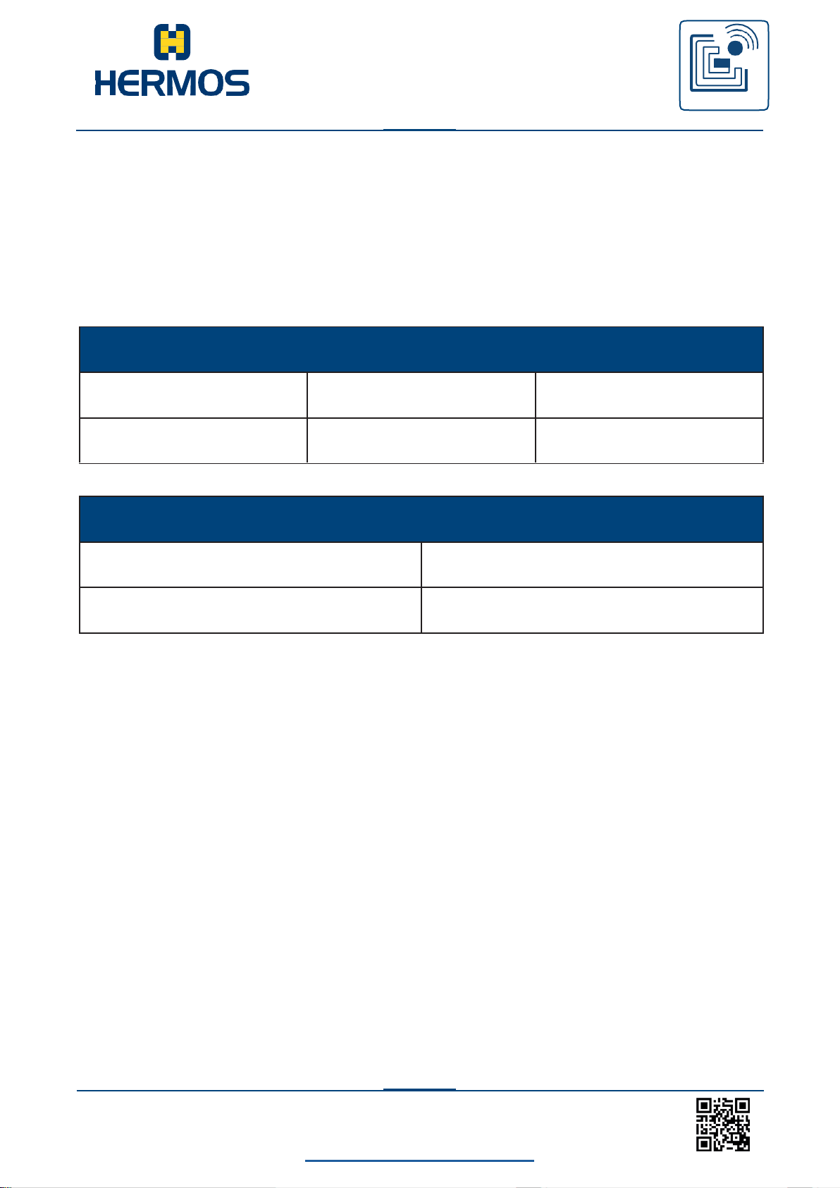
LFM 4x Reader Rev1.4
back to the table of contents
58
www.hermos.com
Customer manual
LFM 4x Reader
RFID
WE GENERATE SOLUTIONS
Host
Device
CMD
Reader-ID
Tuning Value
I
1 Byte
2 Bytes
Device
Host
CMD
Reader-ID
i
1 Byte
10.4.13 I – Adjust RF module
It is necessary to adjust the RF module in ordert to adapt an antenna tot he ambient conditions
optimally. The tuning achieves an optimal read / write range for the present installation
environment. Tuning is performed one at a time for each antenna port and the determined
tuning value is stored for each antenna.
For optimal results, the vote should be automatic, but the voting value can also be set
manually.
To start the auto-tuning process, select the value 08.
Example: I108 … automatic tuning of antenna 1
If the reader can not determine the appropriate calibration, the error „5 - Invalid“ is sent instead
of the confirmation.
Page 60
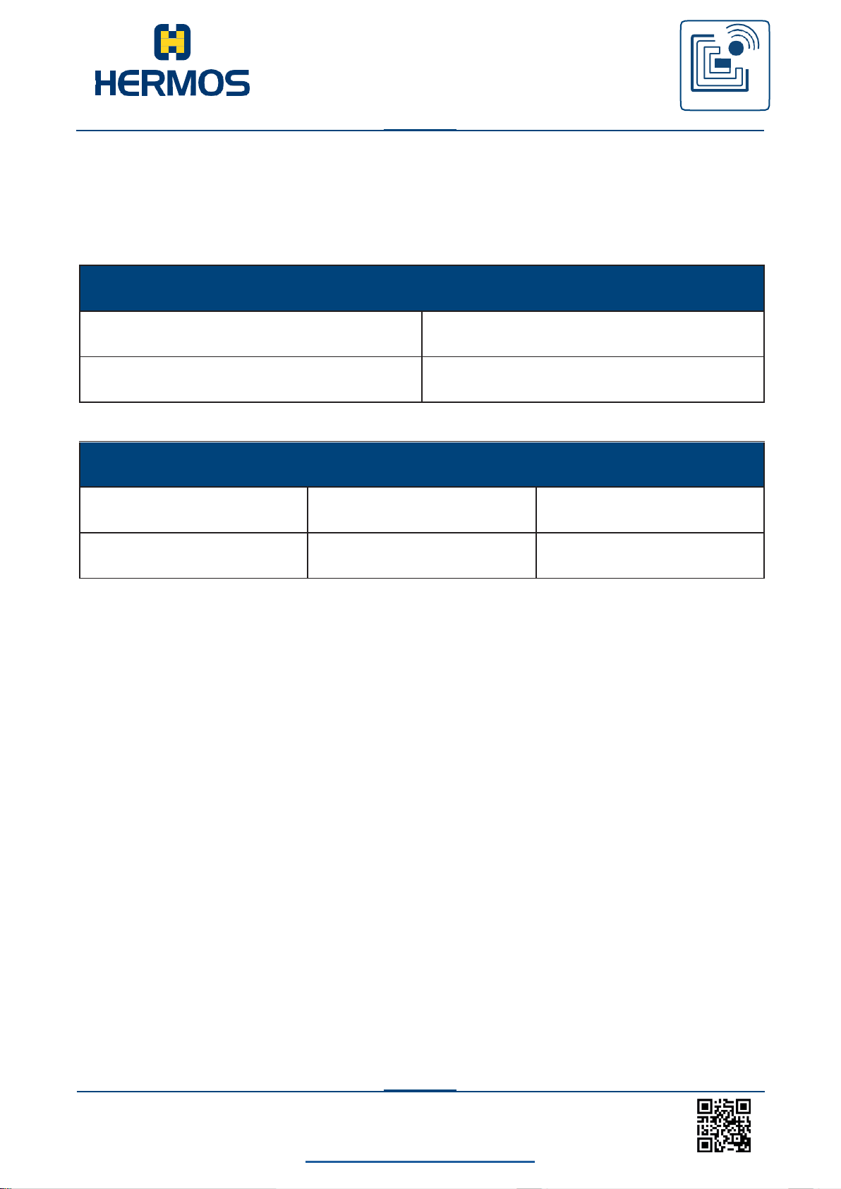
LFM 4x Reader Rev1.4
back to the table of contents
59
www.hermos.com
Customer manual
LFM 4x Reader
RFID
WE GENERATE SOLUTIONS
Host
Device
CMD
Reader-ID
J
1 Byte
Device
Host
CMD
Reader-ID
Tuning value
j
1 Byte
2 Bytes
10.4.14 J – RF module Queries the vote
The command „J“ can be used to query the tuning values of the individual antennas. Each
antenna port has its own tuning value.
The tuning value is a set value for the optimal antenna tuning.
For optimum read and write ranges, the value is automatically determined by the reader
(I-message). The value is measured in 16 steps (0-F).
Page 61
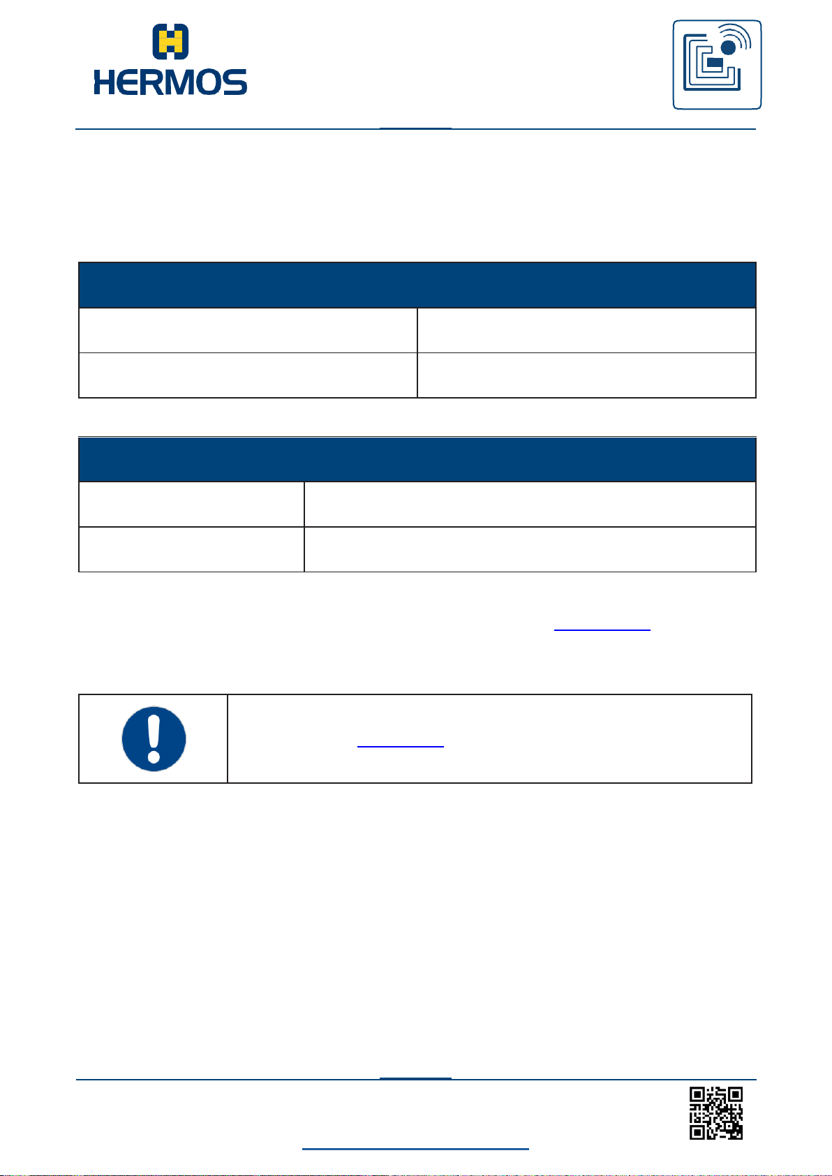
LFM 4x Reader Rev1.4
back to the table of contents
60
www.hermos.com
Customer manual
LFM 4x Reader
RFID
WE GENERATE SOLUTIONS
Host
Device
CMD
Reader-ID
A
1 Byte
LF Lesegerät
Host
CMD
Reader-ID
a
1 Byte
In parameter 1 „Read Mode“ the sensor can be deactivated.
10.4.15 A – Sensor event object removed
The message of sensor events can be activated in the parameter „Watch-Port“ (par. 07). If this
is activated, the reader reports every drop of the external sensor.
The sensor message must be confirmed by the host.
The sensor event is detected after an adjustable delay time (par. 0 Sensor Delay). During the
delay time, the sensor signal must be stable.
Page 62
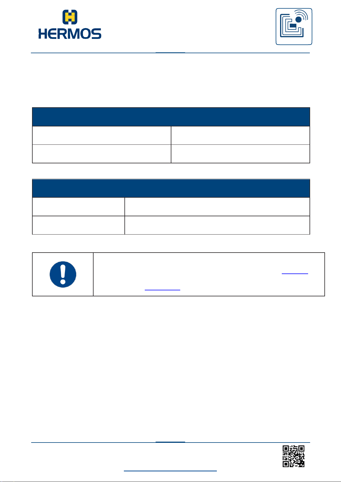
LFM 4x Reader Rev1.4
back to the table of contents
61
www.hermos.com
Customer manual
LFM 4x Reader
RFID
WE GENERATE SOLUTIONS
Host
Device
CMD
Reader-ID
B
1 Byte
Device Host
CMD
Reader-ID
b
1 Byte
The assignment of the external sensor results in an automatic reading and
is not sent as a sensor event in standard ASC-I1 mode. In the ASC-W1
mode, however, a sensor event B is present.
In parameter 1 „Read Mode“ the sensor can be deactivated.
10.4.16 B – Sensor event object detected
The message of sensor events can be activated in the parameter „Watch-Port“ (par. 07). If this
is activated, the reader reports any recognition of the external sensor.
The sensor message must be confirmed by the host.
Page 63
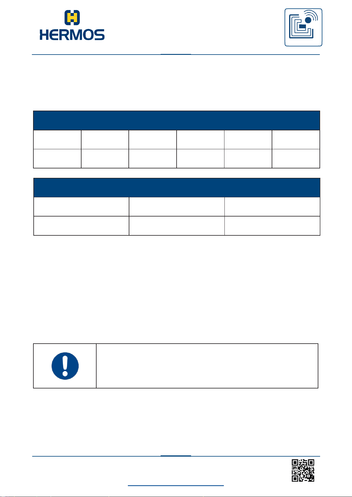
LFM 4x Reader Rev1.4
back to the table of contents
62
www.hermos.com
Customer manual
LFM 4x Reader
RFID
WE GENERATE SOLUTIONS
Host
Device
CMD
Reader-ID
Head-ID
Output
Index
Output
State
Timeout*
O
1 Byte
1 Byte
1 Byte
1 Byte
2 Bytes
The number of available outputs depends on the reader version used.
Device
Host
CMD
Reader-ID
Head-ID
o
1 Byte
1 Byte
10.4.17 O – Set output
The command O can be used to set the state of the outputs.
The status of all outputs is changed in a message. In the current version, the value of the data
element Head-ID always has the value „1“ for the outputs.
* The specification of a time duration (timeout) is optional.
Example: permanently switch on LED 1:
>> O111100
<< 011
Turn red status LED on for 10 seconds:
>> O11310A
<< 011
Page 64
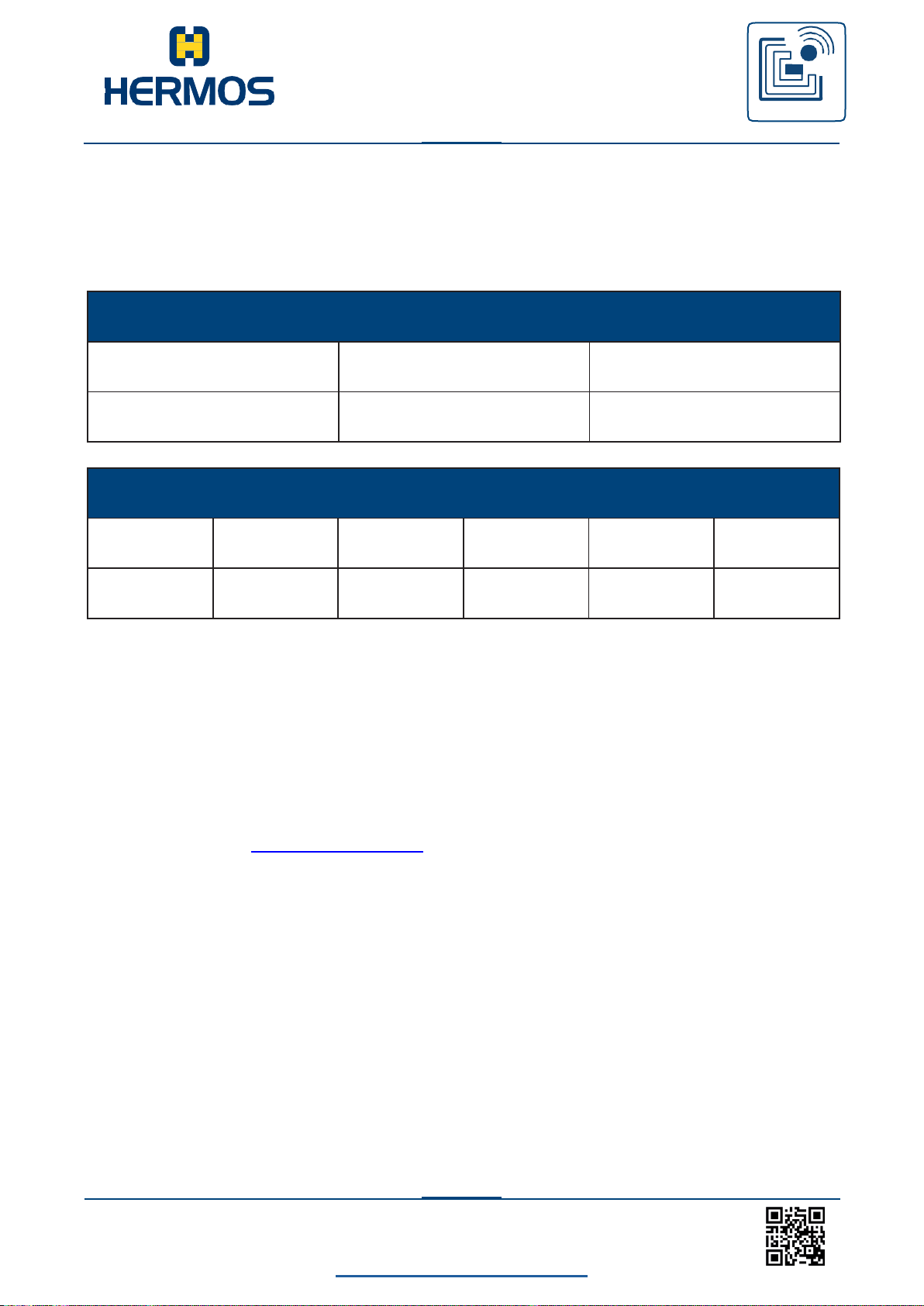
LFM 4x Reader Rev1.4
back to the table of contents
63
www.hermos.com
Customer manual
LFM 4x Reader
RFID
WE GENERATE SOLUTIONS
Host
Device
CMD
Reader-ID
Head-ID
Q
1 Byte
1 Byte
Device
Host
CMD
Reader-ID
Head-ID
Output
Index
Output
State LED1
Output
State LED2
q
1 Byte
1 Byte
1 Byte
1 Byte
1 Bytes
10.4.18 Q – Querying the status of the inputs and outputs
The Q command can be used to query the current status of all outputs. The status of the
outputs is queried in a message. In the current version, the value of the data element Head-ID
always has the value „1“ for the outputs.
Example: Status LEDs Port 1
>> Q11
<< q1121 LED1 (2 = flash), LED2 (1 = on)
The status of all 4 (The number of sensor states may vary between 4 and 6, depending on the
custo- mer mode.) input sensors can be queried via head ID „0“.
In this case, the answer contains the 4 (The number of sensor states may vary between 4 and
6, depending on the Factoryparameterset.) sensor states instead of the 2 output states.
Example: Status of all 4 sensors
>> Q10
<< q100000
Page 65
LFM 4x Reader Rev1.4
back to the table of contents
64
www.hermos.com
Customer manual
LFM 4x Reader
RFID
WE GENERATE SOLUTIONS
The parameters 0, 1, 2 and 7 are only valid if the reader is equipped
with a corresponding I / O module and provides one input per antenna
port.
*): Since software revision V1.5 some parameters are implemented
for each antenna port. Addressing of the parameter takes place via
the reader ID of the message. In this realisation, the parameter is
present once per antenna port. If no parameter arrays should be
used, please ask the manufacturer (parameter 63)!
Nr.
(dez)
Nr.
(hex)
Parameter
name
Description
0
0x00
Sensor delay
Delay time for the presence sensor.
01 .. 99 (0,1 Sekunden)
Default: 10 … (1 second)
Realisation: a separate parameter for each port *)
1
0x01
Read mode
Read mode for reading automatically started by external
input. 00 - read only one page
01 - read until the end character or empty
character2) 02 - read all pages
10 - read only one page with previous sensor Check1)
11 - read until the end character / empty character
with previous sensor check 1) 2)
12 - read all pages with previous sensor
Check1) 99 - Disable sensor
1) If the Sensor Check (first byte = 1) is activated, the assignment of
the potential-free input is checked before initiating a read / write
process. When used, the read / write process is started, otherwise the
error message „NOTAG“ is sent.
2) ‚E‘ or ‚F‘ in ID bits 0...3 of the read ID
Default: 00 … (read only one page)
Realisation: a separate parameter for each port *)
2
0x02
Read page
Page for readmode „00“.
01 First page of each transponder
02.. 17 Side of a multipage
transponder Default: 01 (read first
page)
Realisation: a separate parameter for each port *)
3
0x03
r/w repeat
time
Time between two read / write attempts.
01 .. 99 (0,1 s)
Default: 05 … (0,5 seconds)
Realisation: a separate parameter for each port *)
10.5 Parameter
The data element „Parameter No.“ can have the following values. List of public paramters:
Page 66
LFM 4x Reader Rev1.4
back to the table of contents
65
www.hermos.com
Customer manual
LFM 4x Reader
RFID
WE GENERATE SOLUTIONS
4
0x04
r/w max
repeat
Max. number of read / write
attempts. 01 .. 99
Default: 05
Realisation: a separate parameter for each port *)
5
0x05
RS232 repeat
time
If no confirmation message was received from the host, the device
waits for this time before sending another message.
The number of repetitions is defined in parameter 6 (‚RS232
max repeat‘).
01 .. 99 (0,1 s)
Default: 45 … (4,5 seconds)
6
0x06
RS232 max
repeat
If an acknowledgement is not sent by the host, the device repeats the
message according to the set value.
Only then is an error message sent.
00 - endless
01 .. 99 - Number of attempts
Default: 3
7
0x07
Watch port
Activates / deactivates the event message to the host that the dry
contact (external output) has been opened (Bit0).
Bit0 (=0x01) reporting of contact has been opened:
0 - deactivated
1 - activated
Default: 1
Realisation: a separate parameter for each port *)
F
0x0F
Reader
address
Address of the first antenna port (0 ... E)
Default: 1
Nr.
(dez)
Nr.
(hex)
Parameter
name
Description
2
0x02
Read page
Page for readmode „00“.
00 First page of each transponder
01 … 17 Side of a multipage transponder
Default: 00 (read first page)
Realisation: a separate parameter for each port *)
7
0x07
Watch port
Activates / deactivates the event message to the host that the dry
contact (external output) has been opened (Bit0) or closed (Bit1).
Bit0 (=0x01) reporting of contact has been opened:
0 - deactivated
1 - activated
Bit1 (=0x02) reporting of contact has been closed:
0 - deactivated
1 – activated
Default: 1
Realisation: a separate parameter for each port *)
For ASC-W1 mode the following additional parameters are public:
Page 67
LFM 4x Reader Rev1.4
back to the table of contents
66
www.hermos.com
Customer manual
LFM 4x Reader
RFID
WE GENERATE SOLUTIONS
8
0x08
Fieldstrength
Parameter is without further function.
Range: 00-01
Default: 1
9
0x09
Charge time
Transponder charging time in milliseconds.
Range: 00-FF
Default: 32(50ms)
Realisation: a separate parameter for each port *)
10 0x0A
Verify
Parameter is without further
function. Range: 00-03
Default: 1
11 0x0B
Fallout
Parameter is without further
function. Range: 00-03
Default: 1
12 0x0C
RS232 repeat
time
Parameter is without further function.
Range: 00-FF
Default: 0
13 0x0D
Noiselevel
adjust
Parameter is without further
function. Bereich: 00-FF
Default: 0
14 0x0E
Sensor
polarity
Type of sensor signal to start an automatic read. The setting is
applied for the addressed sensor.
0 … read process when sensor is covered
1 … read process when sensor is uncovered
Default: 0
Realisation: a separate parameter for each port *)
Page 68
LFM 4x Reader Rev1.4
back to the table of contents
67
www.hermos.com
Customer manual
LFM 4x Reader
RFID
WE GENERATE SOLUTIONS
ASCII
HEX
Description
‚S‘ 53
Start character
‚0‘ 30
High byte message length
‚2‘ 32
Lowbyte message length
‚H‘ 48
Message first character: value
‚0‘ 30
Message second character: destination address
CR 0D
End character
‚2‘ 32*)
Highbyte – Checksum XOR
‚4‘ 34*)
Lowbyte – Checksum XOR
‚3‘
33*)
Highbyte – Checksum Addition
‚A‘
41*)
Lowbyte – Checksum Addition
Calculation of the XOR checksum:
53 XOR 30 XOR 32 XOR 48 XOR 30 XOR 0D =
24
‚2‘ ‚4‘
Calculation of the addition-checksum:
53 + 30 + 32 + 48 + 30 + 0D =
(LSB is used)
13A
‚3‘ ‚A‘
10.6 Message examples
*): With TCP / IP transmission in the standard ASC-I1 protocol, the checksum bytes are not
transmitted. In ASC-W1 mode, however, they are also transmitted!
Page 69

LFM 4x Reader Rev1.4
back to the table of contents
68
www.hermos.com
Customer manual
LFM 4x Reader
RFID
WE GENERATE SOLUTIONS
Command
J
Reader-ID
2
(Antenna port 2)
Data
01
(voting value)
The following examples are based on the standard ASC-I1 protocol. The range of the Reader
ID is set from 1 to 4 in this case:
V – Query software version
>> V1
<< v14C464D3449312E35
Command V
Reader-ID 1
Software version ‚4C464D3449312E35 ‘
ASCII „ LFM4I1.5“
I – automatically tune RF module (antenna port 2)
>> I208
<< i2
Commandl I
Reader-ID 2 (Tuning Antenna port 2)
J – RF module Read out tuning value (Antenna port 2)
>> J2
<< j201
X – Read data (Reading from page 1 of the multipage transponder)
>> X101
<< x1014142434445464748
Command X
Reader-ID 1 (reading on antenna port 1)
Page 01
Data
‚4142434445464748‘
ASCII „ABCDEFGH“
R - Automatic reading on antenna port 1
<< R1013132333435363738
>> r1
Command R
Reader-ID 1 (automatic reading on antenna port 1)
Page 01
Data
‚4142434445464748‘
W – Write data (Write antenna port 2, page 16 Multipage)
>> W2103132333435363738
<< w2
Command W
Reader-ID 2 (Write to antenna port 2) Page 10 (10hex = page 16dec.)
Data
‚3132333435363738‘
ASCII „ ABCDEFGH „
ASCII „12345678“
Page 70
LFM 4x Reader Rev1.4
back to the table of contents
69
www.hermos.com
Customer manual
LFM 4x Reader
RFID
WE GENERATE SOLUTIONS
ID
Name
Description
Possible Cause
Corrective action
0
none
No error
none
1
auto fail
Automatic reading is
not possible
Reader is still busy with a
former read or write request
Wait until the previous request has
ended.
2
ext fail
Execution failed, read
or write operation
cannot be carried out
Reader is still busy with a
former read or write request.
Wait until the previous request has
ended.
3
write fail
Data transfer to the tag
is not possible.
Reader is still busy with a
former read or write request.
Wait until the previous request has
ended.
4
no tag
No transponder or
antenna installed
Antenna is not connected
properly
Check antenna connection
Antenna is not tuned
Antenna tuning
No readable transponder
within the reading range
Put the transponder in the antenna
area. Check the type and function of
the transponder
Antenna / transponder are
misaligned
Check the alignment of the antenna
and the transponder
Antenna is damaged or too
close to metal
Replace the antenna, check the
tuning
Interference field at
transmission frequency
Check antenna environment for
possible sources of interference.
(Monitors, servomotors…)
5
invalid
Invalid parameter or
data
Invalid command data
Check command syntax and data
content
Parameter is not
implemented or out of range
Check parameter syntax and value
6
unknown
Unknown errors
none
7
Unconfig
The device is not
configured
Wrong reader address
Check message syntax, check
parameter F „Reader address
8
check
Parity or checksum
error
Wrong baud rate
Check the baud rate of the serial
interface (Com port)
Transmission error at
serial communication
Check RS232 cable and connector,
Check sources of interference with RS232
9
void ackn
unexpected
acknowledge
Serial communication is
interrupted
Check RS232 cable and connector,
Check sources of interference with
RS232
Ethernet communication is
interrupted
Check Ethernet cable and connector,
check IP address settings
Double or wrong
acknowledgment
Check communication settings at the
host
A
Locked
Locked page cannot
be written
Tag is write protected
Check the page number to be written,
exchange the tag for the new one
10.7 Error Codes
Page 71
LFM 4x Reader Rev1.4
back to the table of contents
70
www.hermos.com
Customer manual
LFM 4x Reader
RFID
WE GENERATE SOLUTIONS
B
Unconfig
Maximum number of
send messages has
been confirmed
(RS232 maxrepeat),
The terminal did not
confirm within the
specified timeframe
Host system does not
acknowledge the
message
Check availability oft he host
system, Check RS232 cable and
connector Ethernet cable and
connector, Check IPAddress
settings
C
Bad type
Wrong transponder
type
A wrong transponder type
is used (Read only or
Read / Write instead of
multipage)
Check and replace transponder
type
:
Msg len
Message too long or
too short
or not received
completely
Message too long or too
short or
not received completely
Message length is longer than
indicated on the length byte,
Check message length and length
byte
Message is longer than
specified in the length
byte
Check message length, check
length byte
Not all characters are
transfered (Intercharacter
Timeout)
Check message syntax, Check
RS232 or Ethernet connection
;
Invalid
Invalid command
Unknown command was
received
Check message syntax
Page 72
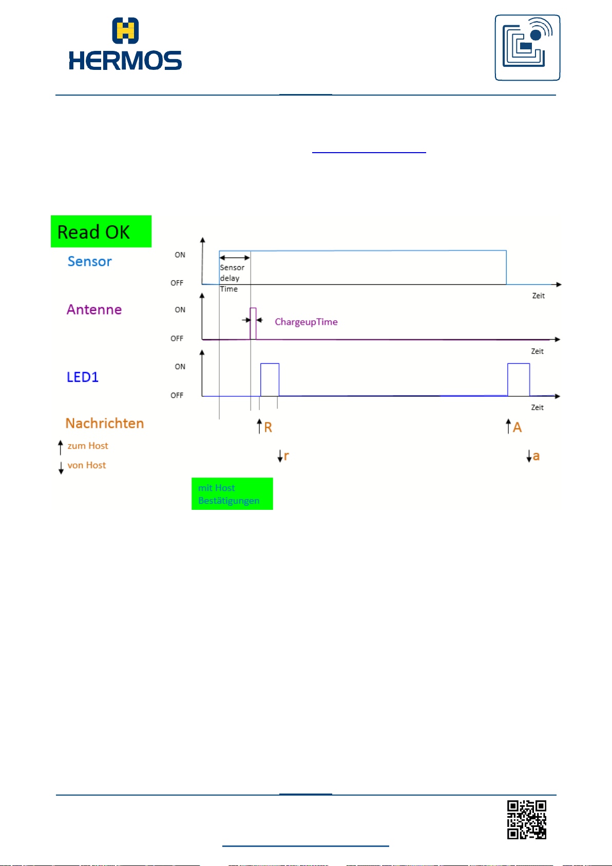
LFM 4x Reader Rev1.4
back to the table of contents
71
www.hermos.com
Customer manual
LFM 4x Reader
RFID
WE GENERATE SOLUTIONS
10.8 Wiring of the outputs
For readers with I / O modules, depending on the Factoryparameterset, the outputs of the
respective antenna port are switched accordingly when reading.
10.8.1 ASC-W1 Mode: Reader in operation mode and sensor triggered reading
Picture 1: Successful reading with instant host confirmation
Page 73
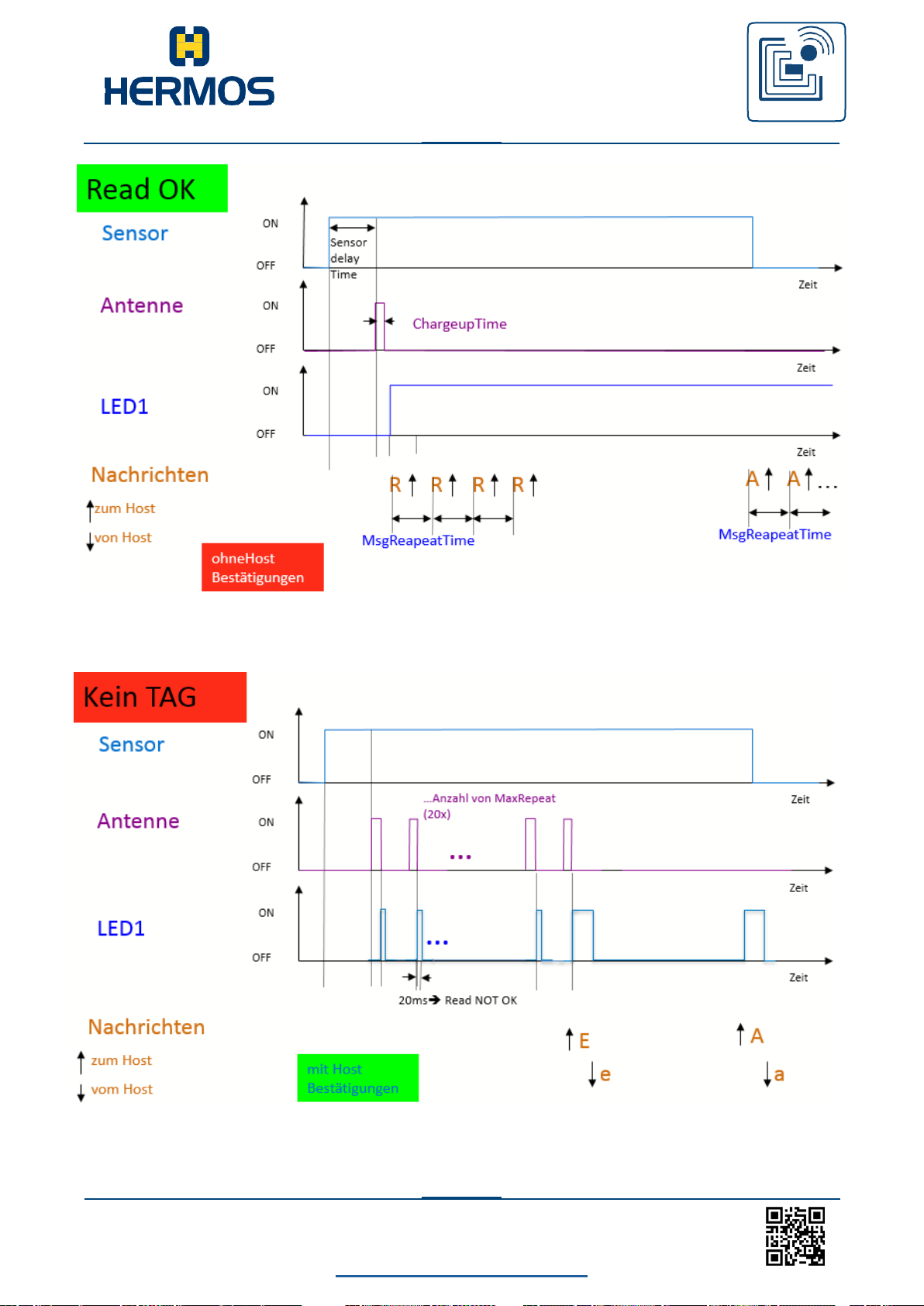
LFM 4x Reader Rev1.4
back to the table of contents
72
www.hermos.com
Customer manual
LFM 4x Reader
RFID
WE GENERATE SOLUTIONS
Picture 2: Successful reading with missing host confirmation
Picture 3: Unsuccessful reading with instant host confirmation
Page 74
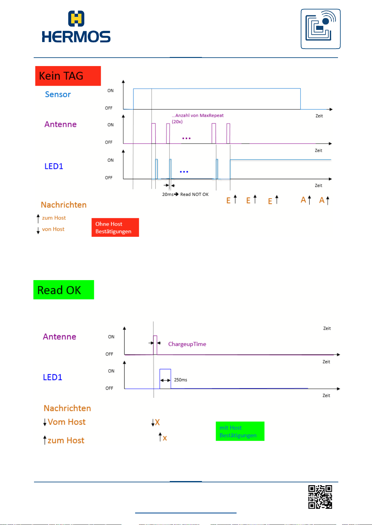
LFM 4x Reader Rev1.4
back to the table of contents
73
www.hermos.com
Customer manual
LFM 4x Reader
RFID
WE GENERATE SOLUTIONS
Picture 4: Unsuccessful reading with missing host confirmation
10.8.2 ASC-W1-Mode: Reader in operation mode and external triggered reading
Picture 5: Successful external reading X
Page 75
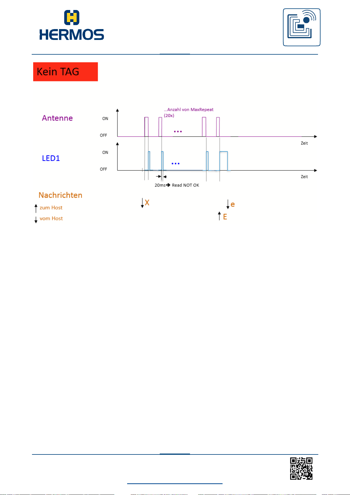
LFM 4x Reader Rev1.4
back to the table of contents
74
www.hermos.com
Customer manual
LFM 4x Reader
RFID
WE GENERATE SOLUTIONS
Picture 6: Unsuccessful external reading X
Page 76
LFM 4x Reader Rev1.4
back to the table of contents
75
www.hermos.com
Customer manual
LFM 4x Reader
RFID
WE GENERATE SOLUTIONS
DEZ
HEX
CTRL
Code
0 0 ^@
NUL
1 1 ^A
SOH
2 2 ^B
STX
3 3 ^C
ETX
4 4 ^D
EOT
5 5 ^E
ENQ
6 6 ^F
ACK
7 7 ^G
BEL
8 8 ^H
BS 9 9
^I
HT
10 A ^J
LF
11
B
^K
VT
12 C ^L
EF
13
D
^M
CR
14
E
^N
SOH
15
F
^O
SI
16
10
^P
DLE
17
11
^Q
DC1
18
12
^R
DC2
19
13
^S
DC3
20
14
^T
DC4
DEZ
HEX
CTRL
Code
21
15
^U
NAK
22
16
^V
SYN
23
17
^W
ETB
24
18
^X
CAN
25
19
^Y
EM
26
1A
^Z
SUB
27
1B
^[
ESC
28
1C
^\
FS
29
1D
^]
GS
30
1E
^^
RS
31
1F
^_
US
10.9 ASCII – table
Page 77
LFM 4x Reader Rev1.4
back to the table of contents
76
www.hermos.com
Customer manual
LFM 4x Reader
RFID
WE GENERATE SOLUTIONS
DEZ
HEX
CTRL
32
20
BLANK
33
21 ! 34
22 " 35
23 # 36
24
$
37
25 % 38
26 & 39
27 ' 40
28 ( 41
29 ) 42
2A
*
43
2B
+
44
2C
,
45
2D
-
46
2E . 47
2F / 48
30 0 49
31 1 50
32
2
51
33
3
52
34 4 53
35 5 54
36 6 55
37
7
DEZ
HEX
CTRL
56
38 8 57
39 9 58
3A : 59
3B ; 60
3C
<
61
3D = 62
3E > 63
3F ? 64
40 @ 65
41 A 66
42
B
67
43
C
68
44
D
69
45
E
70
46 F 71
47 G 72
48 H 73
49 I 74
4A
J
75
4B
K
76
4C L 77
4D M 78
4E N 79
4F
O
Page 78
LFM 4x Reader Rev1.4
back to the table of contents
77
www.hermos.com
Customer manual
LFM 4x Reader
RFID
WE GENERATE SOLUTIONS
DEZ
HEX
CTRL
80
50
P
81
51 Q 82
52
R
83
53
S
84
54 T 85
55 U 86
56 V 87
57
W
88
58 X 89
59 Y 90
5A
Z
91
5B
[
92
5C
\
93
5D
]
94
5E
^
95
5F _ 96
60 ' 97
61 a 98
62
b
99
63
c
100
64 d 101
65 e 102
66 f 103
67
g
DEZ
HEX
CTRL
104
68
h
105
69 i 106
6A
j
107
6B
k
108
6C l 109
6D m 110
6E n 111
6F
o
112
70 p 113
71 q 114
72
r
115
73
s
116
74
t
117
75
u
118
76
v
119
77 w 120
78 x 121
79 y 122
7A
z
123
7B
{
124
7C | 125
7D } 126
7E ~ 127
7F
□
Page 79

LFM 4x Reader Rev1.4
back to the table of contents
78
www.hermos.com
Customer manual
LFM 4x Reader
RFID
WE GENERATE SOLUTIONS
11.SECS / HSMS Communications protocol
The SECS I standard defines a communication interface that is suitable for exchanging
messages between the semiconductor processing systems and a host. A host is a computer or
computer network that exchanges the information with the systems to carry out the production.
The standard does not define the data contained in the message. The meaning of the
messages must be defined by a standard that defines the message content – e.g. by the SEMI
Equipment Communications Standard E5 (SECS-II).
This message record describes the communication between a reading device with SECS-I and
a host. The host and the RFID reading device can communicate via a RS232 interface (SECS-I)
or an Ethernet interface (10/100BaseT) with HSMS protocol. The meaning of the messages is
provided in the message details section in which the message content is defined.
Serial communication (SECS-I):
The data is transmitted or received as a serial bit stream with 10 bits per character in a
supported data rate. A standard character has a start bit, 8 data bits and a stop bit. No parity
bits or other controls are used for transmitting the individual bytes.
Default setting: 19200 / 8N1
Details about the data definition and the data transmission are provide in the SEMI Standard
E4. (SEMI Equipment Communication Standard 1 Message Transfer SECS-I)
Ethernet communication (HSMS):
The reading device functions as a HSMS server. This means that it waits for a connection
request from a HOST PC (client).
TCP/IP: IP-Adress xxx.xxx.xxx.xxx Port 3241
If there is a connection request from a HOST, a HSMS connection is set up and the SECS II
messages defined in the message record are transmitted from the reading device to the
respective HOST and vice versa. The HSMS connection remains intact until it is specifically
terminated by the host or the reading device.
All reading devices available in the network (LAN) can be operated from any HOST PC. A
HSMS reading device, however, can no longer be connected to more than one HOST
simultaneously.
The network settings can be changed using a configuration tool provided by HERMOS. Each
change to the network settings causes the unit to reboot and thus disconnects existing
communication connections.
11.1 Structure of a message
The communication structure and process is defined by the SEMI Equipment Communications
Standards E4, E5 and E37 (SECS-I, SECS-II, HSMS).
SECS message blocks always have a specified structure that consists of 1-4 length bytes, 10
bytes of message headers and message data.
Page 80
LFM 4x Reader Rev1.4
back to the table of contents
79
www.hermos.com
Customer manual
LFM 4x Reader
RFID
WE GENERATE SOLUTIONS
Byte
MSB
Description
Length
0
Length without
checksum
Header
1
R
Upper Device ID
(reader-ID)
2
Lower Device ID
(gateway-ID)
3
W
Upper Message ID
(stream)
4
Lower Message ID
(function)
5
E
Upper block number
6
Lower block number
7
System byte 1
8
System byte 2
9
System byte 3
10
System byte 4
Data
11-254
Message data
Checksum
255, 256
16 Bit checksum
Upper Devic-ID (Reader-ID)
R-Bit 0 0 0 0 0 0 1
The length contains all the bytes transmitted after the length byte with the exception of the two
checksum bytes. The maximum block length allowed by the SECS-I is 254 bytes and the
minimum is 10 bytes.
The reverse bit (R bit) indicates the direction of the message. The R bit (MSB) is set to „0“ for
messages to the reading device and „1“ for messages to the host.
The device ID is a unique number to establish the connection with the reading device. It
consists of an 8-bit gateway ID (bit 0-7) and a 7-bit reader ID (bit 8-14). The gateway ID in the
delivery state corresponds to the last two hexadecimal characters of the serial number of the
reader. The reader ID has the value 0x01 in the delivery state. Of course, the device ID can be
changed via the corresponding parameters Gateway ID and Reader ID within the validity range.
See example with Reader ID 0x01 and Gateway ID 0x00:
Page 81
LFM 4x Reader Rev1.4
back to the table of contents
80
www.hermos.com
Customer manual
LFM 4x Reader
RFID
WE GENERATE SOLUTIONS
Lower Device-ID (Gateway-ID)
0 0 0 0 0 0 0 0
Direction reading device to host 0x8000
Direction host to system (reading device) 0x0000
The W bit indicates whether the transmitter of the primary message wait for a reply. If the W bit
contains the value 1, it means that a reply is expected.
The message ID determines the format and the content of the transmitted message. It consists
of a stream and a function. The stream defines the message group and the function, the exact
meaning and the syntax of the message. A primary message (request) is defined as an
uneven message. A secondary message is defined as an even message (reply).
The end bit indicates whether a block is the last block of the message. A value of 1 means
that the block is the last block. Since all messages can be transmitted in a block, the block
number always has the value 1.
The system bytes in the header of each message are used to distinguish primary messages.
The system bytes of the reply message must correspond to the system bytes of the
corresponding primary message. The system bytes are incremented for each primary
message.
The checksum is calculated as the numerical sum of the unsigned binary values of all bytes –
after the length byte and before the checksum as well as in an individual block.
For more detailed information about the structure and transmission procedure, see SEMI E4,
E5, E37, E99.
(SEMI Equipment Communication Standard Message Transfer SECS)
Page 82
LFM 4x Reader Rev1.4
back to the table of contents
81
www.hermos.com
Customer manual
LFM 4x Reader
RFID
WE GENERATE SOLUTIONS
0
...
Sensor 0 was the Initiator
1
...
error, not accepted
0
...
No error
1
...
error, not accepted
0
...
No error
1
...
error, not accepted
ACKC3 Format: B[1]
ACKC5 Format: B[1]
ALARM STATE Format: A[1]
ALCD Format: B[1]
11.2 Directory Data Elements
This section defines the data elements used in the standard SECS-II messages described
in the message details section.
Syntax:
Name A unique name for this data item. This name is used in the message definitions
.
Format A unique name for this data item. This name is used in the message
definitions. The allowed element format code that can be used for this
default data element. Element format codes are displayed in
hexadecimal and octal, as described in chapter Data element.
The notification „3 ()“ indicates a signed integer format (30, 31, 32, 34).
Description A description of the data element with the meaning of each value. Where used
standard messages in which the data element occurs.
Verification code
Verification code
The value of the alarm state refers to the last read. If a read or write error occurs, the alarm state
is activated. A successful read or write deactivates the alarm state. When leaving the
maintenance mode, the alarm state is also deactivated.
Alarm-Codebyte
Only the occurrence of an error is reported. Errors are usually not reset.
Bit 8 = 1 Alarm activated
Where used S5F1
Page 83
LFM 4x Reader Rev1.4
back to the table of contents
82
www.hermos.com
Customer manual
LFM 4x Reader
RFID
WE GENERATE SOLUTIONS
ALID Format: B[1]
ALID Format: A[max40]
Alarm Identifier
Only the occurrence of an error is reported. Errors are usually not reset.
0 No error
1 Automatic reading failed, the reader is busy
2 External read failed, the reader is busy
3 External write failed, the reader is busy
4 No transponder could be detected when the
sensor was covered, or the carrier was removed
too soon (sensor uncovered)
5 Invalid command or parameter detected
6 Unknown error
7 Reserved
8 parity error or checksum error detected
9 An unexpected confirmation has been sent
10 Locked page could not be described
11 Reserved
12 Wrong transponder type
13 External read or write failed because the sensor is not covered
14 Reserved
15 Reserved
16 Reserved
More about error codes and the corresponding corrective measures can be found in
the chapter Error Codes.
Where used S5F1
Alarm text
The length of the alarm text is between 0 and 40 characters. Depending on the version of the
reader, information about the condition of the sensor or the sensors is also transmitted in the
event of an error message from the reader
The information should be interpreted as follows:
ALTX[0] Initiator of an error message
“0”: Sensor 0
“1”: Sensor 1 (not available)
“F”: Not assignable
ALTX[1] State of the sensor 0
“0”: Sensor is not used
“1”: Sensor is busy
“E”: Sensor status is not available
“F”: Sensor is not sent
ALTX[3] ‘:’ a semicolon separates the alarm text from the sensor states
Where used S5F1
Page 84
LFM 4x Reader Rev1.4
back to the table of contents
83
www.hermos.com
Customer manual
LFM 4x Reader
RFID
WE GENERATE SOLUTIONS
ATTRID Format: A[max25]
Name for an attribute for a specific object type.
CIDRW Attribut definitions:
„Configuration“ Number of heads
„AlarmStatus“ Current CIDRW sub-state of the alarm state
„OperationalStatus“ Current CIDRW sub-state in normal operation
“SoftwareRevisionLevel“ Change (version) of the software - maximum 8 bytes
„CarrierIDOffset“ Offset of the CID in the CID field (MID area)
„CarrierIDLength“ Length of the CID in the CID field (MID area)
„SERIALNUM“ Series number string
„HARDWARE“ String of the Hardware-Release
„SELF_TEST_RESULT“ Supply the result of the last self-test
„MANUFACTURER“ String of the manufacturer
„ECID_00“
„ECID_01“
„ECID_02“ Parameter 2 Inter-character timeout T1
„ECID_03“ Parameter 3 Block protocol timeout T2
„ECID_04“ Parameter 4 Reply timeout T3
„ECID_05“ Parameter 5 Inter-block timeout T4
„ECID_06“ Parameter 6 Retry limit RTY
„ECID_07“ Parameter 7 TARGETID high byte
„ECID_08“ Parameter 8 TARGETID low byte
„ECID_09“ Parameter 9 Heartbeat time
„ECID_11“ Parameter 11 ReaderID
„ECID_12“ Parameter 12 HeadID
„ECID_20“ Parameter 20 Sensor Delay for presence sensor
„ECID_22“ Parameter 22 Sensor triggered action for presence sensor
„ECID_23“ Parameter 23 Triggered read frequency
„ECID_24“ Parameter 24 r/w max repeat
„ECID_25“ Parameter 25 Transponder Type
„ECID_26“ Parameter 26 Sensor activity
„ECID_27“ Parameter 27 Sensor Watchport for presence sensor
„ECID_29“ Parameter 29 Transponder load duration (read mode)
„ECID_30“ Parameter 30 r/w synchronize
„ECID_33“ Parameter 33 Automatic Antenna adjustment
„ECID_34“
„ECID_35“
„ECID_36“
Parameter 0 Gateway ID
Parameter 1 Baudrate
Parameter 34 Sensor type for presence sensor
Parameter 35 Special features
Parameter 36 DIP switch activation
Page 85
LFM 4x Reader Rev1.4
back to the table of contents
84
www.hermos.com
Customer manual
LFM 4x Reader
RFID
WE GENERATE SOLUTIONS
ATTRVAL Format: A[max4]
„ECID_37“ Parameter 37 MID area
„ECID_38“ Parameter 38 Test after software reset
„ECID_40“ Parameter 40 Transponder load duration (write-mode)
„ECID_41“ Parameter 41 Delay time between read cycles
„ECID_42“ Parameter 42 CarrierIDOffset
„ECID_43“ Parameter 43 CarrierIDLength
„ECID_44“ Parameter 44 FixedMID
„ECID_45“ Parameter 45 MIDFormat
„ECID_75“ Parameter 75 DIP switch state (read only)
„ECID_80“ Parameter 80 Auto adjust value antenna port 1 (read only)
„ECID_81“ Parameter 81 Auto adjust value antenna port 2 (read only)
„ECID_82“ Parameter 82 Auto adjust value antenna port 3 (read only)
„ECID_83“ Parameter 83 Auto adjust value antenna port 4 (read only)
„ECID_97“ Parameter 97 Default protocol (read only)
„ECID_98“ Parameter 98 Protocol change allowed
„ECID_99“ Parameter 99 Customer Code
Header attribute definitions:
„HeadStatus“ Current state corresponds to „OperationalStatus“
„HeadID“ Headnumber 00-xx (2Ziffern)
Where used S5F1
Value of the specified attribute.
CIDRW-attribute definitions:
„Configuration” Number of antenna ports „04“
„AlarmStatus” Current CIDRW sub-state of the
ALARM STATUS „0“ …NO
„1“ …ALARMS
„OperationalStatus“ Current CIDRW sub-state of IN OPERATION
„IDLE“ …reader is rest mode
„BUSY“ …reader is busy
„MANT“ …maintenance mode
„SoftwareRevisionLevel“ Revision (version) of the software (max. 8 bytes)
„SERIALNUM“ serial number string (max. 15 bytes)
„HARDWARE“ String of the hardware release (max. 10 bytes)
Page 86
Customer manual
LFM 4x Reader
RFID
WE GENERATE SOLUTIONS
LFM 4x Reader Rev1.3
back to the table of contents
80
www.hermos.com
The number of LEDs per antenna input depends on the design of the
hardware.
CPVAL Format: A[]
„SELF_TEST_RESULT“ Returns the result of the last self-test. A self-test can
be triggered by message S18F13 using SSCMD.
„MANUFACTURER“ String from the manufacturer „HERMOS“
„ECID_00“ bis „ECID_99“ see data element ECV parameters 0 - 99
Head attribute definitions:
„HeadStatus“ Current state
„IDLE“ Reader in REST mode
„BUSY“ reader is busy
„NOOP“ Not in operation
„HeadID“ corresponds to the 2-digit target ID of the first antenna port
„01“ or „00“
Where used S18F2, S18F3
State request value
OpStatus Operating status, maintenance or rest mode
„OP“ ... operating status
„MT“ ... maintenance status
LEDStatus LED-status
„Off“ ... switch off the LED
„On“ ... switch on the LED
„Flash“ ... switch the LED to flashing mode with 1Hz
LedNo LED-number, 1 Byte
„1“ first LED of the Reader Heads (if available)
„2“ second LED of the Reader Heads (if available)
„3“ red status LED of the reader
„4“ green status LED of the reader
Timeout Timeout duration, Units seconds
„00“: permanently
„01“ bis „FF“: Timeout from 1 to 255 s. After the timeout, the LED goes off.
Where used S18F13
Page 87
Customer manual
LFM 4x Reader
RFID
WE GENERATE SOLUTIONS
LFM 4x Reader Rev1.3
back to the table of contents
81
www.hermos.com
EAC Format: B[1]
„01“
...
page 1
...
„81“
...
Locked page 1
...
„11“
page 17
„91“
Locked page 17
DATA Format: A[max200]
DATALENGTH Format: U2
DATASEG Format: A[2]
ECID Format: U1
The data element is a vector or string of unformatted data.
The DATA area depends on the MID area of the transponder and can be between page 1 and
page 17. Read-write transponder DATA corresponds to 8 byte MID
Read-only transponder DATA corresponds to 8 byte MID
Where used S18F6, S18F7
The DATA LENGTH corresponds to the number of bytes to be read or written. The
scope depends on the length of the MID range (parameter 37).
Where used S18F5, S18F7
Used to identify the requested data.
The DATASEG corresponds to the page number (PAGEID) of the transponder.
„00“ First page of each transponder or first page of the DATA area.
Multipage transponders (pages 1 to 17):
Read-Only-Transponder „F0“ Read only one page
Read-Write-Transponder „F1“ Read or write only one page
Where used S18F5, S18F7
Confirmation code for new reader attribute
0 ... parameter successfully set
1 ... parameter could not be set
Where used S2F16
Parameter number of the reader.
The values are displayed as decimal values.
Where used S2F13, S2F15
Page 88
Customer manual
LFM 4x Reader
RFID
WE GENERATE SOLUTIONS
LFM 4x Reader Rev1.3
back to the table of contents
82
www.hermos.com
Please note the parameters 42-45
ECV Format: U1
MDLN Format: A[6]
MF Format: B[1]
MHEAD Format: B[10]
MID Format: A
Value of the reader parameter.
The values are displayed as decimal values, see parameters.
Plant model number (Hardware version)
Where used S2F14, S2F15
Material Format Code
20: The material port number corresponds to the sensor number and the sensor status.
Where used S1F2
Where used S3F5, S3F7
The data element MHED consists of the head of the SECS message block associated with the defective
message block.
Material ID, predefined area on the transponder in which the unique identifier of the cassette / box is
stored. Depending on the type of transponder, the length of the MID can be changed.
Multipage-Transponder: The MID length can be set from „0“ (no MID) to „10“ (MID occupies
the first 10 pages).
Read-Write-Transponder: The MID corresponds to the DATA (writable) Read-OnlyTransponder: The MID corresponds to the DATA (fixed)
Where used S9F1, S9F3, S9F5, S9F9
Where used S18F10, S18F11
Page 89
Customer manual
LFM 4x Reader
RFID
WE GENERATE SOLUTIONS
LFM 4x Reader Rev1.3
back to the table of contents
83
www.hermos.com
OFLACK Format: B[1]
MIDRA Format: B[1]
MIDAC Format: B[1]
ONLACK Format: B[1]
PAGEDATA Format: B[9]
Material ID verification code
0 Material ID confirmed; the presence sensor was the initiator
1 Not specified
2 Material ID confirmed - reaction to externally triggered process; the message can not be assigned
to a sensor
>2 Material ID not confirmed
The initiator can be taken from the data element PTN.
Where used S3F14
Material ID verification code
2 confirmation, MID will be sent later in S3F13
Where used S3F12
Confirmation code for OFFLINE request.
0 ONLINE accepted (reader is online)
Confirmation code for ONLINE request.
0 ONLINE accepted (reader is online)
Where used S1F16
The data element corresponds to the transponder data. It contains the transponder page and the data
content of the page.
PAGEDATA [0] Correspond to the page number. The value of the page number is displayed in
PAGEDATA [1-8] The 8 bytes (one page) of the transponder ID follow.
Where used S1F18
the data element „DATASEG“.
Where used S3F7, S3F13
Page 90
Customer manual
LFM 4x Reader
RFID
WE GENERATE SOLUTIONS
LFM 4x Reader Rev1.3
back to the table of contents
84
www.hermos.com
SHEAD Format: B[10]
RAC Format: B[1]
PTN Format: B[1]
PM Information Format: A[2]
RIC Format: B[1]
Information about the condition of up to two sensors and the initiator of the message.
Initiator Bit0 ….Bit 4:
The initiator sets the number of the sensor that triggered the message.
1 … 4 port1 to port4
Sensorstate Bit5 ….Bit 7:
The current state of the sensor is described with 3 bits.
0 … Sensor is not occupied
1 … Sensor is occupied or detected
7 … Sensor not defined
Example: 0x24 means Sensor ist deteced (0x20) and the initiator was sensor at port4 (0x04)
Where used S3F5, S3F7, S3F13
Information about the operating mode
„NE“ … normal execution
„MR“ … operating mode „maintenance“ required
Confirmation code reset
0 … Reset could be executed
1 … Reset could not be executed
Where used S18F2, S18F4, S18F8, S18F10, S18F12, S18F14
1 … Power-up-Reset
2 … Software reset (without reset of the Ethernet component)
Head of the stored SECS message block. Only the last message is saved. This must be confirmed by
the host.
Where used S18F20
Where used S2F19
Where used S9F9
Page 91
Customer manual
LFM 4x Reader
RFID
WE GENERATE SOLUTIONS
LFM 4x Reader Rev1.3
back to the table of contents
85
www.hermos.com
SSCMD Format: A[max 18]
SOFTREV Format: A[max 6]
SSACK Format: A[2]
Software version
Where used S1F2
Result information about the status of the request for the service request.
„NO“ Normal Operation
Indicates the success of the requested operation.
„EE“ Execution error
Transponder data cannot be read. MID sequence cannot be read, as valid ASCII characters were not
found exclusively in the defined MID area. However, the condition of the facilities is normal.
„CE“ Communication error
Syntax error in message, message format, or value.
„HE“ Hardware error
Error in the head of the ID reader / writer, head of the ID reader / writer is deactivated.
„TE“ Transponder error, reading / writing unsuccessful (Tag Error)
„NT“ No transponder detected in the antenna area. (No Tag)
Where used S18F2, S18F4, S18F8, S18F10, S18F12, S18F14
Specifies an operation to be performed by the subsystem. Used to distinguish between the various
subsystem commands displayed.
„ChangeState“ … change status
„GetStatus“ … query staus
„Reset“ … reset CIDRW
„PerformDiagnostics“ … A diagnosis is made.
„ADJUST“ … triggers an automatic alignment of the antenna.
„HERMOSDefParams“ … Basic setting of the readers parameters.
„SetLED „ … Set one of the device LEDs.
CPVAL‘s 1 <LEDStatus>
2 <Timeout>
3 <LEDNo>
Where used S18F13
Page 92

Customer manual
LFM 4x Reader
RFID
WE GENERATE SOLUTIONS
LFM 4x Reader Rev1.3
back to the table of contents
86
www.hermos.com
Status list Format: A[2]
TARGETID Format: A[2]
The status list provides information about the system status.
Consists of „PM Information“ and the current values of the CIDRW attributes „AlarmStatus“, „Operating
Status“ and „HeadStatus“.
Status list
L,4
<PMInformation>
<AlarmStatus>
<OperatingStatus>
<HeadStatus>
Where used S18F2, S18F4, S18F8, S18F10, S18F12, S18F14
The TargetID is defined with 2 decimal ASCII characters and corresponds to the antenna connections. The
2-digit target ID (Head-ID) is used to set the antenna port 1 to 4 for which the action is to be carried out.
(see Adressing the antenna ports). The use of the 4-digit TARGETID is currently not supported.
Where used S18F1, S18F3, S18F4, S18F7, S18F9, S18F11, S18F13
Page 93

Customer manual
LFM 4x Reader
RFID
WE GENERATE SOLUTIONS
LFM 4x Reader Rev1.3
back to the table of contents
87
www.hermos.com
• Are you there request
S1F1
(Host Reader)
•
Request Offline
S1F15
(Host
Reader)
• Request Online
S1F17
(Host
Reader)
Stream 2: (System control)
• Read parameter
S2F13
(Host
Reader)
• Write parameter
S2F15
(Host
Reader)
• Transmit reset
S2F19
(Host
Reader)
Stream 3: (Material state)
• MID detected by sensor
S3F5
(Reader Host)
• MID removed from sensor
S3F7
(Reader Host)
• Read MID
S3F13
(Reader Host)
• Alarm message
S5F1
(Reader Host)
Stream 9: (System error)
• Unrecognised device ID
S9F1
(Reader Host)
• Unrecognised stream type
S9F3
(Reader Host)
• Unrecognised function type
S9F5
(Reader Host)
• Invalid data
S9F7
(Reader Host)
• Transmission timeout
S9F9
(Reader Host)
Stream 18: (System state)
• Read parameter
S18F1
(Host
Reader)
• Write parameter
S18F3
(Host
Reader)
• Read data
S18F5
(Host
Reader)
• Write data
S18F7
(Host
Reader)
• Read MID
S18F9
(Host
Reader)
• Write MID
S18F11
(Host
Reader)
• Subsystem command
S18F13
(Host
Reader)
11.3 Protocol commands
The message record describes the communication data between a reading device with and a
host. The following functions can be used via commands by the host in the reading device or
automatically transmitted from the reading device to the host:
Stream 1: (System state)
Stream 5: (Exception handling)
Page 94
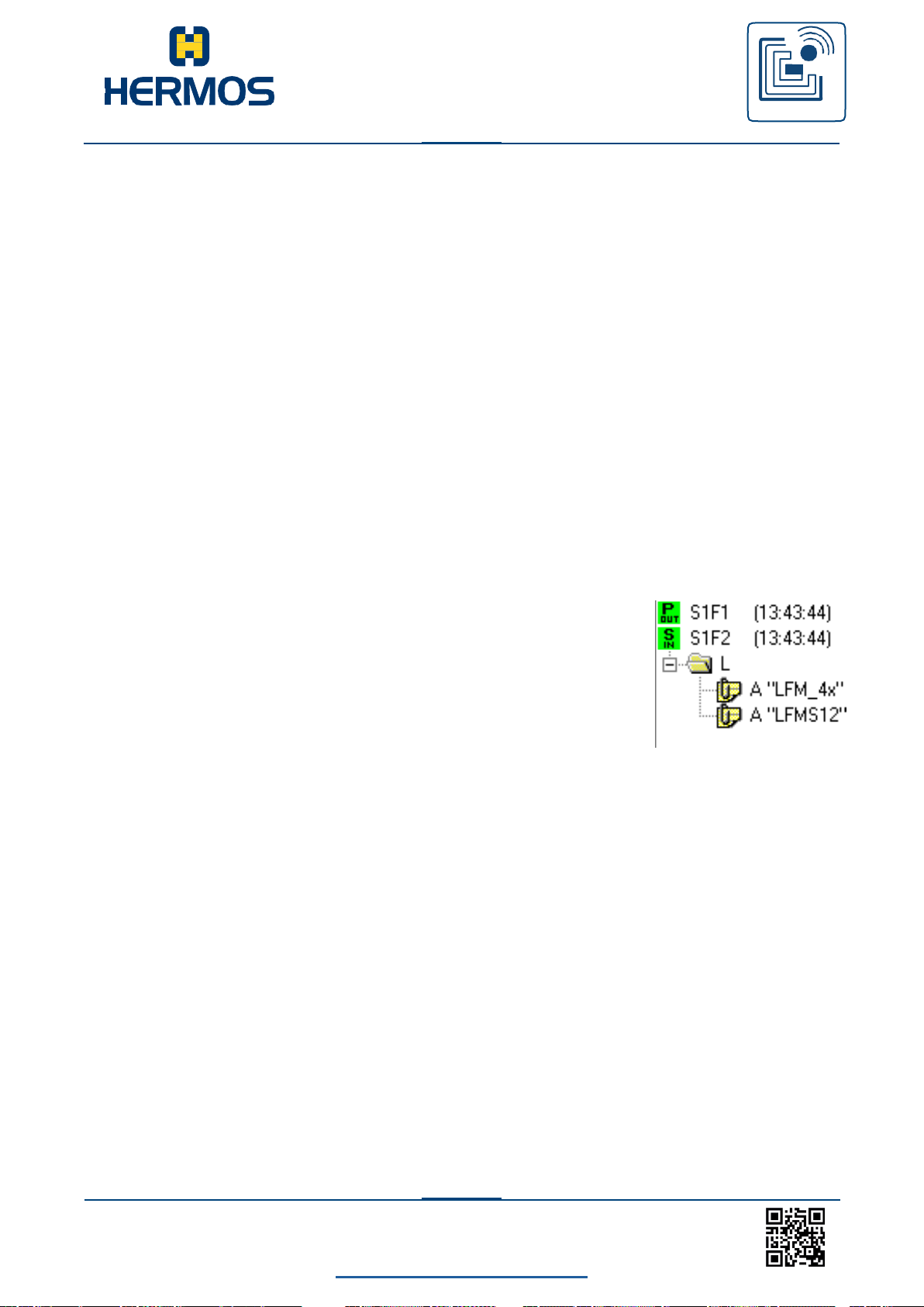
Customer manual
LFM 4x Reader
RFID
WE GENERATE SOLUTIONS
LFM 4x Reader Rev1.3
back to the table of contents
88
www.hermos.com
11.3.1 Stream 1 (system state)
S1F0: ABORT TRANSACTION (reading device <-> host)
This message is used instead of an expected reply to cancel an action. The function 0 is defined
in each stream and has the same meaning in each stream.
S1F0 (header only, no additional elements)
S1F1: ARE YOU THERE REQUEST (reading device <-> host, reply)
Determines whether the reading device or the host is online. S1F1 W (header only, no additional
elements)
S1F2: ON-LINE DATA (host -> reading device)
The host indicates that it is online.
S1F2
<L[2]
<A[6] MDLN >
<A[6] SOFTREV
S1F2: ON-LINE (reading device -> host)
The reading device indicates that it is online.
S1F2
<L[2]
<A[6] MDLN >
<A[6] SOFTREV >
>
S1F15: REQUEST OFF_LINE (host -> reading device, reply)
The reading device contains a request to change the communication state to „offline“.
The reading device can only be set to „online“ again using the message S1F17 (or reset S2F19);
all other messages are cancelled by message SxF0.
.
S1F15 W (header only, no additional elements)
Page 95
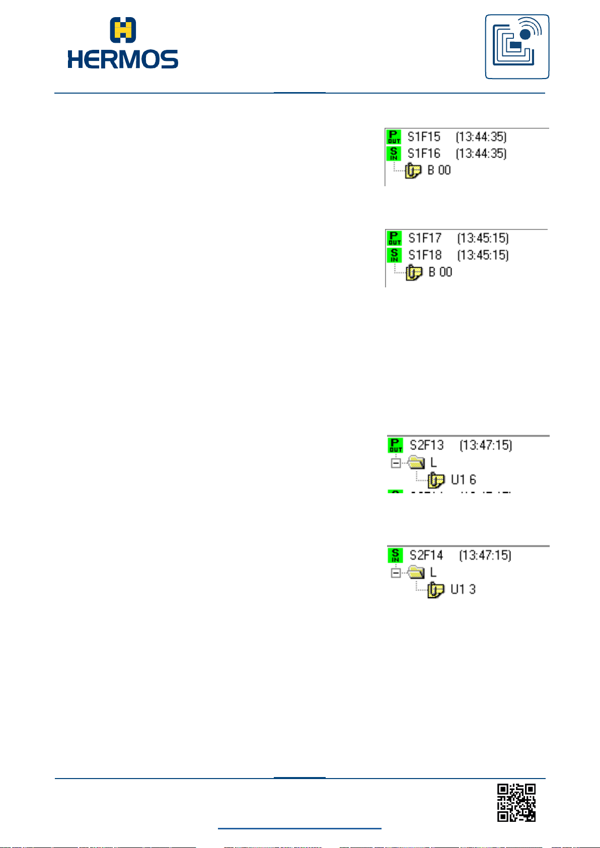
Customer manual
LFM 4x Reader
RFID
WE GENERATE SOLUTIONS
LFM 4x Reader Rev1.3
back to the table of contents
89
www.hermos.com
S1F16: OFFLINE ACKNOWLEDGE (reading device -> host)
Acknowledgement.
S1F16
<B[1] OFLACK>.
S1F17: REQUEST ON_LINE (host -> reading device, reply)
The reading device contains a request to change the communication state to „online“. S1F17 W
(header only, no additional elements)
S1F18: ONLINE ACKNOWLEDGE (reading device -> host)
Acknowledgement
S1F18
<B[1] ONLACK>
11.3.2 Stream 2 (system control)
S2F0: ABORT TRANSACTION (reading device <-> host)
This message is used instead of an expected reply to cancel an action. S2F0 (header only, no
additional elements)
S2F13: EQUIPMENT CONSTANT REQUEST (host -> reading device, reply)
The host requests an attribute (parameter) from the reading device.
S2F13 W
<L[1]
<U1[1] ECID>
>
S2F14: EQUIPMENT CONSTANT DATA (reading device -> host)
The reading device transmits the requested attribute (parameter) to the host.
S2F14
<L[1]
<U1[1] ECV>
>
Page 96
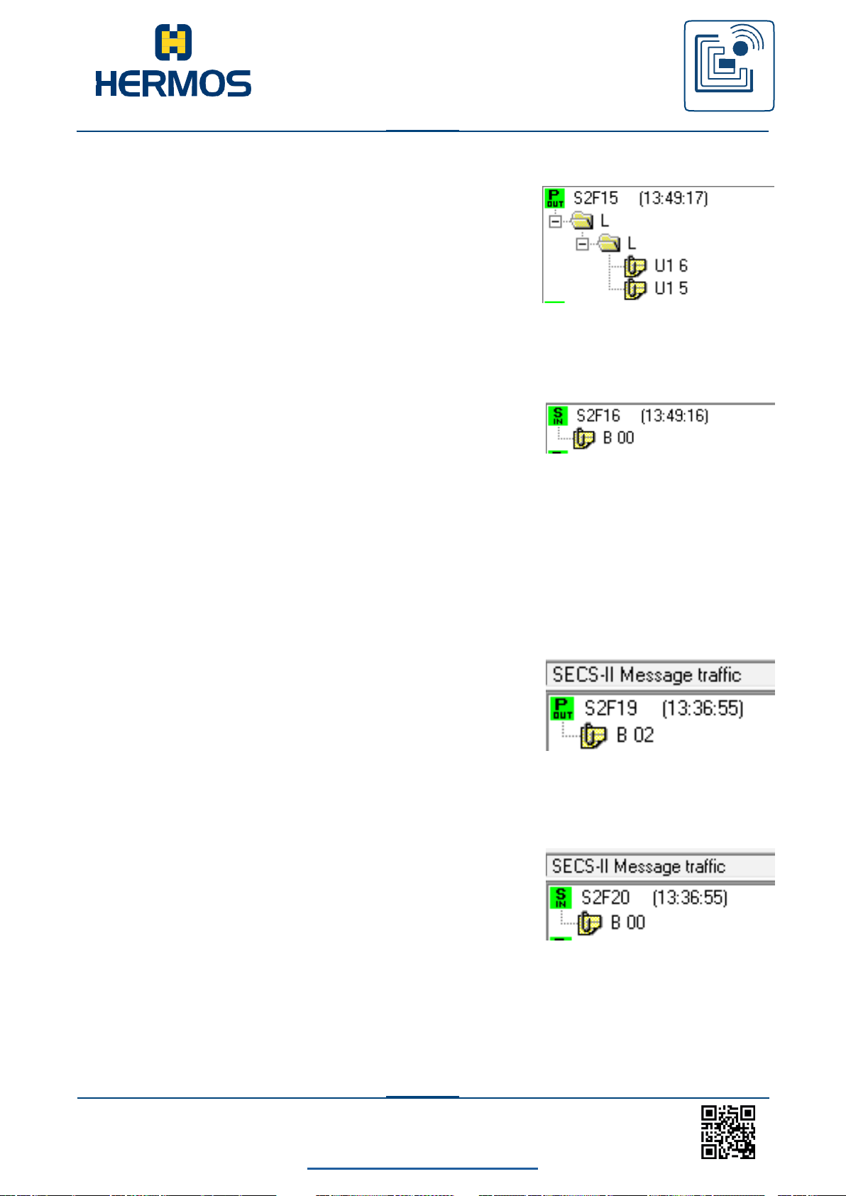
Customer manual
LFM 4x Reader
RFID
WE GENERATE SOLUTIONS
LFM 4x Reader Rev1.3
back to the table of contents
90
www.hermos.com
S2F15: NEW EQUIPMENT CONSTANT SENT (host -> reading device, reply)
The host changes a reading device attribute (parameter).
S2F15 W
<L[1]
<L[2]
<U1[1] ECID>
<U1[1] ECV>
S2F16: NEW EQUIPMENT CONSTANT ACKNOWLEDGE (reading device ->host)
The reading device acknowledges the reading device parameter).
S2F16
<B[1] EAC>
S2F19: RESET SENT (host -> reading device, reply)
The host transmits a request to the reading device to reset the hardware and software.
If a heartbeat time (parameter 9) is set, the reading device transmits a S1F1 message once the
reset operation is complete.
A power-up reset takes a few seconds.
S2F19 W
<B[1] RIC>
S2F20: RESET ACKNOWLEDGE (reading device -> host)
The reading device acknowledges the reset.
This message is only displayed if a software reset (RIC=2) has been triggered.
S2F20
<B[1] RAC>
Page 97
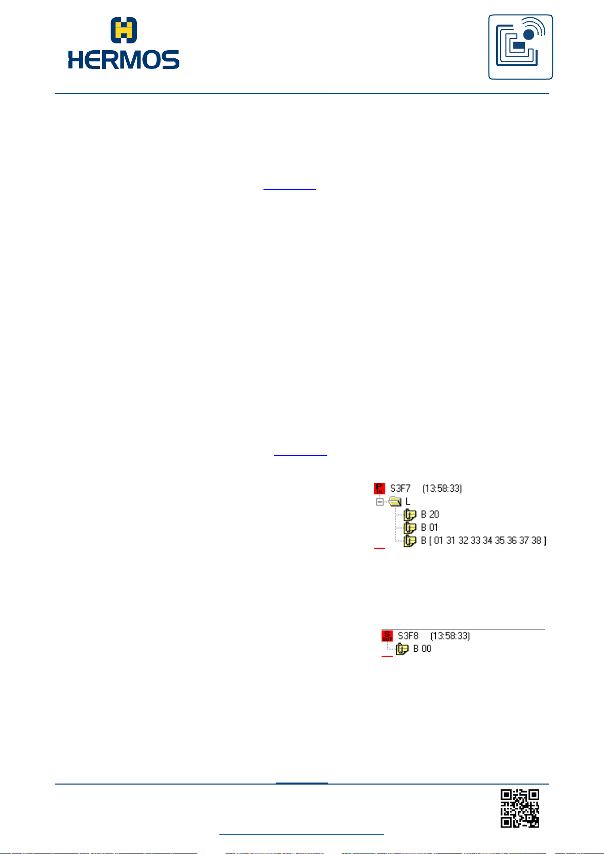
Customer manual
LFM 4x Reader
RFID
WE GENERATE SOLUTIONS
LFM 4x Reader Rev1.3
back to the table of contents
91
www.hermos.com
11.3.3 Stream 3 (Material-state)
S3F5: Material found (MID FOUND) (reading device-> host, reply)
The reader sends the information that material has been detected on the input sensor. This
message is sent only when a sensor is connected and activated.
(see par. 26 Sensor Activity and par. 27 Watchport)
S3F5 W
<L[2]
<B[1] MF >
<B[1] PTN >
>
S3F6: Material found confirmation (MID FOUND, ACK) (host -> reading device)
The host confirms the message material found.
S3F6
<B[1] ACKC3 >
S3F7: Material lost (MID LOST) (reading device -> host, reply)
The reader sends the information that material has been removed from the input sensor. This
message is sent only when a sensor is connected and activated.
(see par. 26 Sensor Activity and par. 27 Watchport)
The PAGEDATA are only indicated if the last reading was successful.
S3F7 W
<L[2]
<B[1] MF >
<B[1] PTN >
<B[9] PAGEDATA >
>
S3F8: Material lost confirmation (MID LOST, ACK) (host -> reading device)
The host confirms the message material lost.
S3F8
<B[1] ACKC3 >
Page 98
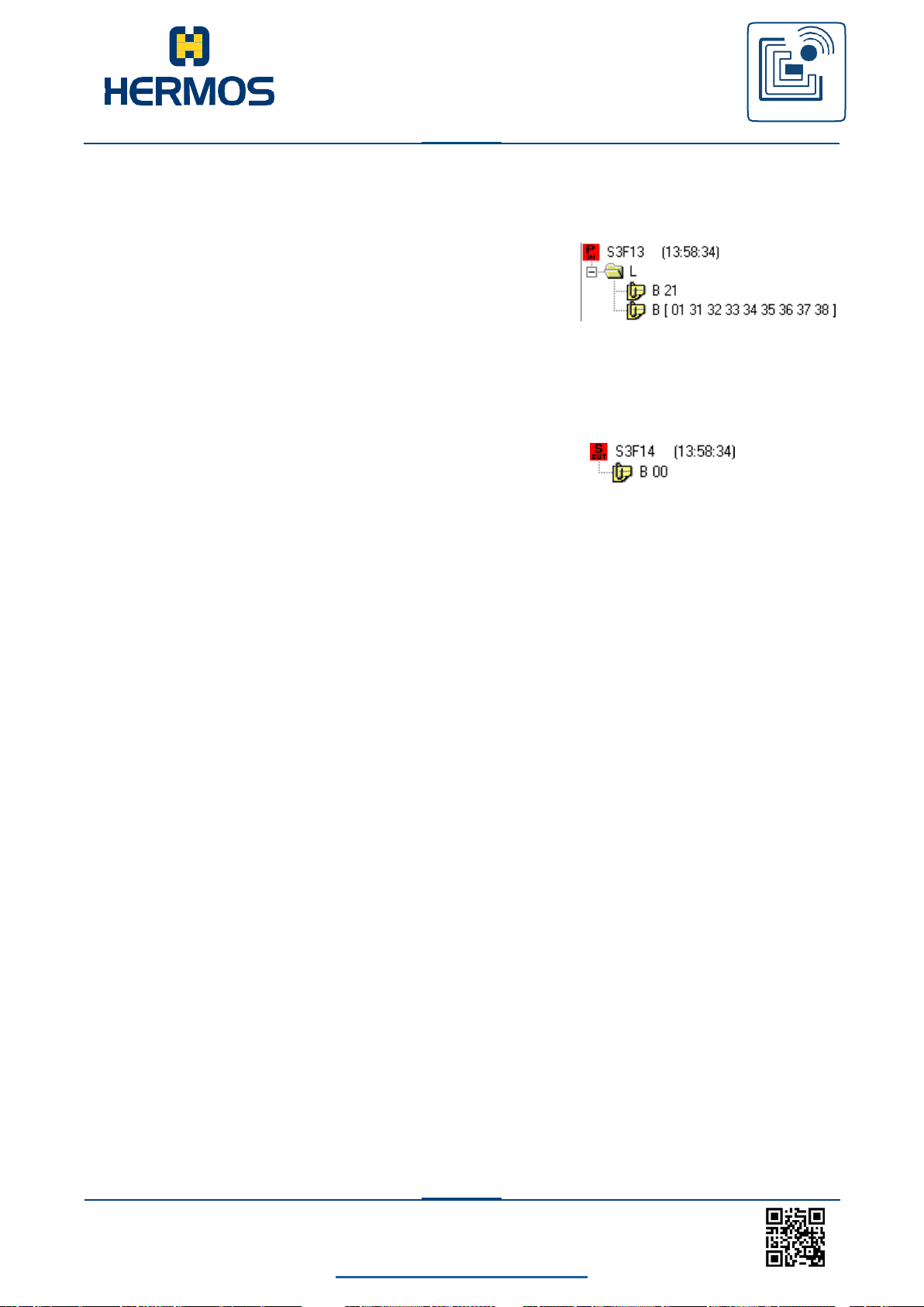
Customer manual
LFM 4x Reader
RFID
WE GENERATE SOLUTIONS
LFM 4x Reader Rev1.3
back to the table of contents
92
www.hermos.com
S3F13: MID found (MID READ) (reading device -> host, reply)
The reader sends the MID of the set up material to the host.
S3F13 W
<L[2]
<B[1] PTN >
<B[9] PAGEDATA >
>
S3F14: Material found confirmation (MID FOUND, ACK) (host -> reading device)
The host confirms the received MID data.
S3F14
<B[1] MIDAC >
Page 99
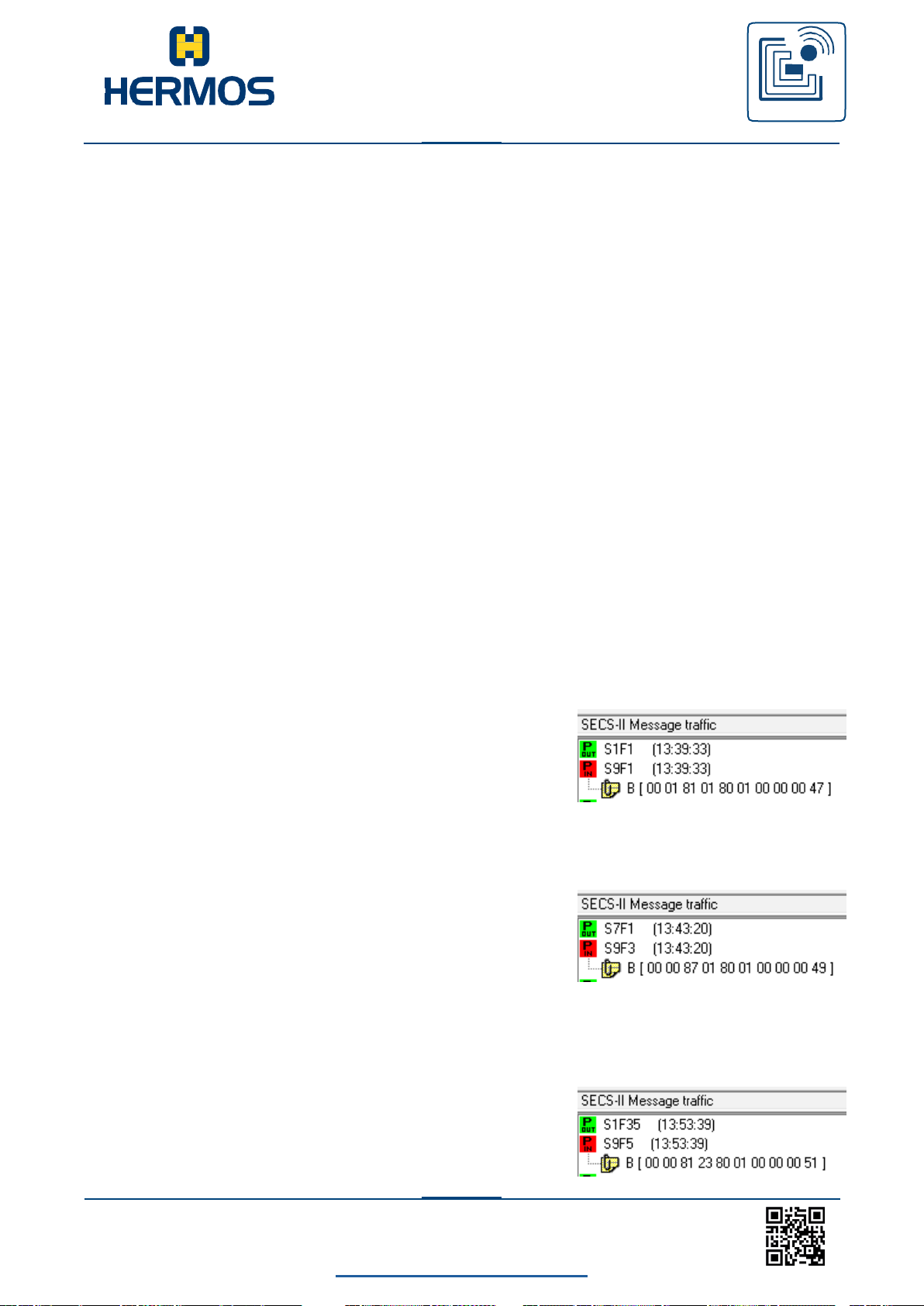
Customer manual
LFM 4x Reader
RFID
WE GENERATE SOLUTIONS
LFM 4x Reader Rev1.3
back to the table of contents
93
www.hermos.com
11.3.4 Stream 5 (Exception handling)
S5F1: Alarm Report (reading device -> host, reply)
The reader reports an error to the host.
S5F1 W
<L[3]
<B[1] ALCD > Alarmcodebyte
<B[1] ALID > Alarm-ID
<A[MAX 40] ALTX > Alarmtext
>
S5F2: Alarm Report confirmation (Host -> Lesegerät)
The host confirms the alarm message.
S5F2
<B[1] ACKC5 >
11.3.5 Stream 9 (system error)
S9F1: UNRECOGNIZED DEVICE ID (reading device -> host)
The device ID in the header of the message block does not correspond to the expected
device ID.
S9F1
<B[10] MHEAD >
S9F3: UNRECOGNIZED STREAM TYPE (reading device -> host)
The reading device does not recognise the stream type in the header of the message block.
S9F3
< B[10] MHEAD >
S9F5: UNRECOGNIZED FUNCTION TYPE (reading device-> host)
The reading device does not recognise the function number in the header of the message
block.
S9F5
< B[10] MHEAD >
Page 100

Customer manual
LFM 4x Reader
RFID
WE GENERATE SOLUTIONS
LFM 4x Reader Rev1.3
back to the table of contents
94
www.hermos.com
S9F7: ILLEGAL DATA (reading device -> host)
The reading device does not recognise the data in the message.
S9F7
< B[10] MHEAD >
S9F9: TRANSACTION TIMER TIMEOUT (reading device -> host)
This message indicates a timeout of a transmission timer and the cancellation of the
corresponding transaction. Only the most recently transmitted message (that must be
acknowledged by the host) is saved and its acknowledgement is monitored by time.
S9F9
< B[10] SHEAD >
 Loading...